
S2016 - Video recorder AXIS - Free user manual and instructions
Find the device manual for free S2016 AXIS in PDF.


| Product Type | Network Video Recorder (NVR) |
| Brand | Axis Communications |
| Model | S2016 |
| Dimensions (H x W x D) | 44 x 440 x 430 mm (1.73 x 17.32 x 16.93 in) |
| Weight | Approx. 4.5 kg (9.9 lb) |
| Power Supply | 100-240 V AC, 50/60 Hz, 1.2 A |
| Power Consumption | Max. 60 W (including HDD) |
| Video Input | Up to 16 IP camera channels |
| Video Compression | H.264, H.265, MJPEG |
| Recording Resolution | Up to 4K (3840 x 2160) per channel |
| Storage | Support for 2 SATA HDDs up to 8 TB each |
| Network Interface | 2 x Gigabit Ethernet RJ-45 |
| USB Ports | 2 x USB 3.0 |
| Operating Temperature | 0 °C to 45 °C (32 °F to 113 °F) |
| Humidity | 10-85% RH (non-condensing) |
| Main Functions | Real-time recording, motion detection, remote access, PTZ control |
| Maintenance | Clean dust from vents and fans; keep firmware updated |
| Safety | Overvoltage protection, surge protection, lockable HDD tray |
| Spare Parts and Repairability | Replaceable HDD, fan, power supply unit; firmware updates via Axis |
| General Information | Supports ONVIF Profile S, axis camera companion app |
Frequently Asked Questions - S2016 AXIS
User questions about S2016 AXIS
0 question about this device. Answer the ones you know or ask your own.
Ask a new question about this device
Download the instructions for your Video recorder in PDF format for free! Find your manual S2016 - AXIS and take your electronic device back in hand. On this page are published all the documents necessary for the use of your device. S2016 by AXIS.
USER MANUAL S2016 AXIS
AXISCameraStationS20ApplianceSeries
AXISCameraStationS2008Appliance
AXISCameraStationS2016Appliance
AXISCameraStationS2024Appliance
AbouttheAXISCameraStationS20ApplianceSeries....3
Setupexamples....4
UseAXISCameraStationS20Applianceinanindependentsurveillance
network....4
UseAXISCameraStationS20Applianceinanexistingnetwork......5
Managethebuilt-inswitch....7
Aboutthebuilt-inswitch....7
Howtoopentheswitch'swebpage....7
Howtoreboottheswitch....7
Howtoimprovesecurityforusedports....7
Howtoimprovesecurityforunusedports......8
Howtoconfiguretheswitch'sIPaddress....8
HowtoconfiguretheDHCPserver......8
Howtoresettheswitchtofactorydefaultsettings....9
Howtochangetheswitch'spassword....9
Howtobackúptheswitch'ssettings....9
Howtorestetheswitch'ssettingstopreviousbackup......9
HowtoaddaVLAN....1.0.
Howtoencrypttrafficctotheswitch'swebpage....1.0.
Overviewtab......10.
PoEtab....12.
ACLtab....13.
VLANtab....13.
HTTPStab....14.
Networktab....14.
Admintab....15.
Productoverview....16
FrontPanelAXISCameraStationS20Series....1.6.
BackPanelAXISCameraStationS20Series....1.7.
LEDIndicators....17.
AbouttheAXISCameraStationS20ApplianceSeries
With an Axis Network Videorecorder you get an easy-to-install and reliable surveillance solution in upto 4K Ultra HD adapted to Axis wider range of network products. Inside an network videorecorder from the AXISCamera Station S20 Appliances series, you'll find two parts: a computer and as switch. The computer part is preloaded with all necessary software you need to create a surveillance solution including the videomanagement software AXISCamera Station. The built-in Powerover Ethernet (PoE) switch simplifies installation and maintenance.
AXISCameraStationS20ApplianceSeriesconsistsofthreedifferentmodels:
•AXISCameraStationS2008Appliance:
8channelclient/serveruptotwomonitors
4TBstorage
IntegratedmanagedPoEswitch
Suitableforinstallationasastandaloneworkstationforofficeenvironments,alsopossibletorackmount.
•AXISCameraStationS2016Appliance:
16channelclient/serverforuptotwomonitors
8TBstorage
IntegratedmanagedPoEswitch
| Difficultylevel | Advanced |
| BenefitsAbilitytouseanAXISCameraStationClienttoconnectto | S2008overthenetwork.Networksegregation. |
| LimitationsMayrequireyoutofollowcorporatenetworkpolices. |
Setupexamples
| Actionsneeded | Changethedefaultpasswordforthebuilt-inswitch.RegistertheAXISCameraStationlicense. |
| Connectorsused | PoEenablednetworkconnectors,port1-8U2servernetwork(forconnectiontonetwork)(Optional)USB3.0connectorx2(forkeyboardandmouse)(Optional)VGAorHDMIconnector |
| ConnectorsNOTused | U1switchuplinkSFP1switchuplinkSFP2servernetworkeSATAconnectorUSB2.0connectorx2(frontpanel) |
Managethebuilt-inswitch
Aboutthebuilt-inswitch
TheAXISCameraStationS20ApplianceSeriescomeswithanintegratedPoweroverEthernet(PoE)switch.Youconfigureandmanage thebuilt-inswitchfromawebpage.
The purpose of the switch histosegregatetrafficonthenetworksothatsecuritycamerasandrelatedtrafficmanagedbytheswitch (PoEportsandU1networkconnections) are not shared with other networks.
Theswitch'spowermanagementfollowtheserules:
- Eachportreservespoweraccordingtotheconnectedpowereddevice'sPoEclass.
- If the actual power consumption for given port exceed the reserved power for that port, it will shutdown.
- Portswillshutdownwhentheactualpowerconsumptionforallportsexceedsthetotalamountofpowerthatthe powersupplycandeliver.Theportsarethenshutdownaccordingtotheportsprioritywherealowerportnumbermeanshigherpriority.
Howtoopentheswitch'swebpage
From you desktopoperthGe Started application and go PolSwitch.
2.ClickGotoPoEswitchwebsite.
Logwithusenamadminanspasswordsystem.
The first time you log in you'll be prompted to change the password.
Note
Youcanalsoopentheswitch'swebpageviaabrowser:entertheswitch'slPaddress192.168.50.1inthebrowser's addressfield.
Howtoreboottheswitch
Important
While the switchreboots, all connected devices will temporarily lose connection with the switch (including PoE).
- Opentheswitch'swebpage.
2.GotoAdmin>Maintenance.
3.ClickRebootswitch.
Howtoimprovesecurityforusedports
YoucanlockaMACaddressstoaportsothatonlytrafficcomingfromthatMACaddresswillpass.Thisimprovessecurityandprevents unauthorizedusersfromconnectingalaptoporotherdevicestothesecuritynetwork.
- Opentheswitch'swebpage.
2.GotoACL. - ForeachportyouwanttolocktheMACaddressfor, clickACLenabled.
Note
ClickEnableallItolocktheMACaddressesforallportsatonce.
Howtoimprovesecurityforunusedports
Youcandisableportsthatyoudonotuse.Thisimprovessecurityandpreventsunauthorizedusersfromconnectingalaptopor otherdevicestothesecuritynetwork.
- Opentheswitch'swebpage.
2.GotoOverview>Portstatus. - Foreachportyouwanttodisable, turnoffPortenabled.
Howtoconfiguretheswitch'slPaddress
Youcanchangetheswitch'sIPaddressbutformostcamerainstallationswerecommendtousethedefaultsettings.Thereasonfor thisisthatasurveillancenetworkisnormallyisolatedfromothernetworks,forexampleacorporateLAN.Inthiscase,youwould onlyusethesurveillancenetworktomanageandcollectsurveillancedevicesanddatafromthevideomanagementsoftware installedontheserver.
Important
MakesureyourecordthenewlPaddress.Ifyou'veforgottenthenewlPaddress,contactAxissupport.
Note
Thefactorydefaultsettingsare:astaticIPconnectionwithaddress192.168.50.1andasubnetmaskwithaddress255.255.255.0.
- Opentheswitch'swebpage.
2.GotoNetwork>Configuration.
EnterAddressSubnetmaskGatewayDNSandDNS.
4.ClickSave. - Reboottheswitch.
HowtoconfiguretheDHCPserver
Important
Iftheswitch'sDHCPserverisenabledandtheAXISCameraStationS20ApplianceisconnectedtoanexternalnetworkwithitsownDHCPserverviatheU1orSFP1connectors,youwillhavelPaddressconflicts.Thismightresultinthecorporatenetworknotworking.
YoucanconfiguretheswitchtouseitsinternalDHCPserverforassigningIPaddressestoconnecteddevices.WhenyouusetheU1 connectiontoallowdevicestoaccessorbeingaccessedbyexternalapplication,youmustspecifythegatewayandDNSaddresses.
- Opentheswitch'swebpage.
2.GotoNetwork>DHCPserver.
EnterStartAddressEndAddressSubnetmaskGatewayDNSDNSandLeaslength.
4.ClickSave.
5.Reboottheswitch.
Howtoresettheswitchtofactorydefaultsettings
Note
If you've forgotten your new IP address or password and can't access the switch, contact Axis support.
- Opentheswitch'swebpage.
2.GotoAdmin>Maintenance. - ClickResettofactorydefault.
- Reboottheswitch.
Howtochangetheswitch'spassword
Youcanchangethedefaultpasswordtoapasswordyouchooseyourself.
Important
Makesureyouselectapasswordyouremember.Ifyou'veforgottenthenewpassword,contactAxissupport.
- Opentheswitch'swebpage.
- GotoAdmin>Security.
EnteUsenamandPassword.
4.EntertheNewpasswordandconfirmit.
5.ClickSave.
6.Reboottheswitch.
Howtobackuptheswitch'ssettings
Note
The username and password are not included in the backup file.
- Opentheswitch'swebpage.
2.GotoAdmin>Maintenance. - ClickBackupsettings.
4.Savethe.gzfile.
Howtorestoretheswitch'ssettingstoppreviousbackup
Note
Torestoretheswitch'ssettingsyoumustpreviouslyhavecreatedabackupfile.
- Opentheswitch'swebpage.
- GotoAdmin > Maintenance.
3.ClickBrowse. - Select the appropriate.gzfile. Makesure that the model name and serial number in the filename match your device.
ClickRestoreOncthesettingsarestoredthewitchwilautomaticallyebootacceptalrestoredchanges.
The username and password are not included in the rest of file. You have to log into the switch's web page with the same credentials as before you restored these settings.
HowtoaddaVLAN
WerecommendtocreateaseparateVLANforendpointsotherthandevicesbelongingtothesurveillancesystem.Eachmember of theVLANcanonlycommunicatewithothermembersoftheVLANwiththeexceptionoftheswitch'swebpage.EveryVLAN,ifits endpointisenabledtoincludeanIPaddressinthesamesubnetastheswitch'swebpage,canbrowsetotheswitch'swebpage(ifyou havethecorrectcredentials).Inthisway,switchadministratorscanneverbelocked-outfromtheswitch.
Example
You could create a second VLAN for IP phones, printers, or computers sharing the same switch. The default VLAN (VLAN1) would then be used strictly by the security system. In this way, you prevent traffic from a separate network with different purposes to include with a general access to security equipment or access security traffic and vice versa.
Note
Firmwareversion1.4.5.418orhighersupportsVLAN.
- Opentheswitch'swebpage.
GoVLANandlicAdd. - Selectwhichport, uplinkorCPU connections you want to add to thenew VLAN.
Eachport, uplink, or CPU connection can only belong to one VLAN at a time.
(Optional) Click the VLAN name field and type description for example "Building A2ndflocameras".
- Reboottheswitch.
Howtoencrypttrafficctotheswitch'swebpage
YoucanimplementHTTPStoaddatransportlayerencryption(TLS)ondatathatpassesfromthebrowsertotheswitch.This is importantwhenyouresettheswitch'spasswordtopreventnon-authorizedusersfromobtainingtheswitch'spasswordthrough unencryptedtraffic.
The devices support sthreemodes for implementing HTTPS: HTTPonly, HTTPor HTTPS (based on the URL selected), or HTTPS only. If you want to encrypt traffic, were recommend to disable HTTPandonly use HTTPS.
- Opentheswitch'swebpage.
- GotoHTTPS>Managecertificate.
- Generateaself-signedcertificateoruploadmatchingbundle, certificate, and keyfiles.
BeforeyoucanactivateHTTPS,theswitchverifiesthatthesearevalidandthatthefilesmatch. - GotoAdministration.
Select HTTPS and disable HTTP.
6.Reboottheswitch.
Overviewtab
In the Overview by you find information about the device resource usage and format status.
| PaneFunctionDescription | ||
| Systeminformation | ModelThedevice'smodelname. | |
| SerialnumberThedevice'sserialnumber.Canbeusefulformaintenanceorwhenyouneedtotrackindividualdevices. | ||
| Firmwareversion | Thefirmwareversioninstalledonyoudevice.Canbeusefultodeterminewhetheryouneedtoupgradetheswitchfirmware. | |
| PortcountThenumberofnetworkportsthedevicesupports,includingacorporateuplinkport. | ||
| MaxPoE | Thetotalpoweravailableforpoweroverethernet(PoE)devices. | |
| ResourceusageTotalPoEusage | Displayshowmuchpower(inwatts)thePoEdevicesconnectedtotheswitchareusing.Oncethemaximumpowerhasbeenreached,thedeviscannotprovideanyfurtherpower. | |
| PoEstatusIndicateswhetherPoEisenabledandhowmanyportshavebeenenabledtosupportPoE. | ||
| ACLstatus | IndicateswhetherACL(AccessControlList)isenabledandhowmanyportsareenabledwiththisaddedsecurityfeature.ACLbindsaspecificMACaddressstoaport,preventingtraffic(sentoreceived)fromdeviceswithotherMACaddresses. | |
| PortstatusPort#Theportnumbertowhichtheselecteddeviceisconnected. | ||
| LinkstateUpindicatesthatadeviceisconnectedtothisport.Downindicatesthatnodeviceisconnected. | ||
| LinkspeedThecurrentnegotiatedlinkspeedforeachport. | ||
| TransmitrateAnoverviewoftrafficloadoneachportshowingtheaveragedatarateinmegabitspersecondforoutbounddataontheport. | ||
| ReceiverateAnoverviewoftrafficloadoneachportshowingtheaveragedatarateinmegabitspersecondforinbounddataontheport. | ||
| Powerdraw | Theaveragepower(inwatts)beingdrawnviaPoEbythedeviceattachedtotheport. | |
| PoEstatusDisplaysifPoEisenabledordisabledforeachport. | ||
| ACLstatusDisplaysifACLisenabledordisabledforeachport. | ||
| Portenabled | Allowsyoutoviewandchangetheenabledordisabledportstatus(theport'sabilitytoreceiveorsenddata).thisisseparatefromthelinkstatusandPoE.AdisabledportmayormaynotstillbeprovidingpowertoaPoEdevice,anditmaystillbephysicallyconnectedtodevice,butitcannotbeusedtosendorreceivedata,eventoughitslinkstatusmaystillbeUpandtheattacheddeviceisstilldrawingpower.Disablingtheportpreventasyndevicefromaccessingtheswitchornetwork.Portsthatarenotinuseshouldbedisabledforincreasedsecurity. | |
| Uplink1 | IfU1orSFP1containsanactiveconnectionitwilldisplayUp.IfU1orSFP1containsannon-activeconnectionitwilldisplayDown.Themaximumlinkspeedandaveragetransmitandreceivedatainmegabitspersecondhelpyouunderstandtrafficpatternsandverifyoperationalstatusofassociatedapplications. | |
PoEtab
InthePoEabyouinformationaboutsetupandstatuspowerveEthernet(PoEforeachportandothePoEnabled devicesasawhole.Thisdataisusefulforsetting,enabling,disabling,andmanagingtheswitch'spowerbudget.
| PaneFunctionDescription | |||||||||||
| PortstatusPort#Theappliance | eportnumbertowhichtheselecteddeviceisconnected. | ||||||||||
| LinkstateUpindicatesthatadeviceisconnectedtothisport.Downindicatesthatnodeviceisconnected. | |||||||||||
| PoEmodeTypeofdevicetheswitchhasdetected.Thisisnotconfigurable,thevaluesareassignedbytheswitchbasedonitsinteractionandpowerdrawoftheconnecteddevice.PoEmodevaluesareeitherATorAF.ThesevaluesrefertotheIEEE802.3atorIEEE802.3afstandards. | |||||||||||
| PoEclassTypeofdevicetheswitchhasdetected.Thisisnotconfigurable,thevaluesareassignedbytheswitchbasedonitsinteractionandpowerdrawoftheconnecteddevice.PoEClassvaluesrangefromOto4andcorrespondtothefollowingpropertiesasdefinedintheIEEEstandard: | |||||||||||
| Theamountofpower(inwatts)drawnbyalldevicescurrentlyconnectedtotheswitch. | |||||||||||
| Thetotalpowerconsumed(inwattsandpercentages)byallconnecteddevices.Thisinformationishelpfulwheninstallingdevicesandverifyingyourpowerbudget. | |||||||||||
| PortsenabledThenumberofportsthatarecurrentlyenabledfordataprovidingpower overEthernet. | |
| MasterPoEAllowsyoutoenableordisablePoEforallportsinonecommand. |
ACLtab
In the ACLtabyoufindinformationaboutaccesscontrolis(ACL)settings, thisabyoucarfoexampledockMACaddress toaportsothatonlytrafficcomingfromthatMACaddresswillbepassed. Thisimprovessecurityandpreventsunauthorizedusers fromattachingalaptoporotherdevicestothesurveillancenetwork.
| PaneFunctionDescription | ||
| AdministrationPortsenabled | ThenumberofportsboundtoaspecificMACaddressusingACL. | |
| MasterACLEnablesordisables | ACLforallportswithaboundedMACaddress.Only portswithadiscoveredMACaddressorboundedaddresswillbeaffected. | |
| PortstatusPort#Theportnum | mbertowhichtheselecteddevice | isconnected. |
| LinkstateUpindicatesthatade | deviceisconnectedtothisport. | |
| Downindicatesthatnodeviceisconnectedtothisport | ||
| DiscoveredMAC addresses | TheswitchautomaticallydetectstheMACaddresssofanydevice connectedtotheportanddisplaysithere.Datatrafficwillonlybe allowedtoorfromthisMACaddress. | |
| BoundMACaddressesEnabling | ACLwillbindtheporttothediscoveredMACaddress.Noother devicewillbeabletocommunicateonthisport.WhenyouenableACL, ifherisDiscoveredMACAddresswillmovetheBoundMAC Addresscolumn,bindingittothisport. | |
| UnauthorizedMAC addresses | DisplaystheMACaddresssofanyunauthorizedcameraorothernetwork deviceattemptingtosendtrafficoveranACLenabledport. | |
| PoEstatus | DisplaysthecurrentPoEstatus(enabledordisabled). | |
| When AvailableAC, if her is Discovered MACAddresswillmove theBoundMACAddresscolumnpindingthiporDisabling ACLclearstheBoundMACAddressvaluesoyoumaybindadifferent devicetothisport. | ||
VLANtab
IntheVLANtab,youfindinformationabouthowtoaddandmanagevirtualLANs(VLAN).
| Description | Function | |
| aticallygeneratednam | oftheVLAN. | |
| Themanually | Make descriptionoftheVLAN. | |
| Selectall | AddsallavailableportstotheVLAN. | |
| 18 | Theavailableport Thenumberdependonthedevicemodel. | |
| 1-16 | ||
| 1-24 | ||
| orkconnectiontothesen | U1 | |
| CPUCPU. |
| DHCP | Theswitch'sDHCPserverisonlyavailableonVLAN1(default).DHCPwilldisplayasenabled oncetheswitch'sDHCPserverisactivatedintheNetworktab. |
| IfotherVLANsrequireDHCPaddressassignment,anexternalDHCPservermustbeprovided andaccessiblewithinthenetworksofVLANs2orgreater. | |
| DeleteWhenyoudeleteaVLAN,anymemembersofthatVLANareimmediatelyreturnedtothemembershipofVLAN1,thedefaultVLAN. | |
HTTPStab
IntheHTTPStab,youfindinformationaboutcertificatesandHTTPSsettings.
| PaneFunctionDescription | ||
| AdministrationHTTPTurnonoroffHTTP. | ||
| HTTPSTurnonoroffHTTPS. | ||
| Currentcertificate | Version | Informationabouttothecurrentlyinstalledcertificate(third-partyor self-signed),ifany.Toupdatecertificatesoranyoftheinformationinthispaneoncenew certificatesorkeysareprovided,youmustreboottheswitch.Once rebooted,theswitchwilldisplaythemostcurrentcertificateinformation. |
| Serialnumber | ||
| Signaturealgorithm | ||
| Validfrom | ||
| Validto | ||
| Subject | ||
| Issuer | ||
| Fingerprint | ||
| Managecertificate | CAbundlefile | Thesefieldsallowyoutogenerateaself-signedcertificateorupload matchingbundle,certificate,andkeyfiles. |
| Certificatefile | ||
| Privatekeyfile | ||
| Selectcountry | ||
| Organization | ||
| Commonname | ||
Networktab
IrtheNetworklayoucanconfigurehdAddressofthewitchandmanagethebuilt-irDHCBerverTheDHCBervercontrols theassignmentofIPaddressesdevicesconnectedtotheswitch'sports.
| PaneFunctionDescription | ||
| Configuration | IPaddressTheIPaddressofthe | U1switchconnection.Youcanopentheswitch'swebpagethroughthisaddress |
| Subnetmask | ThesubnetmaskoftheU1switchconnection. | |
| Gateway | ThegatewayforaccessingtheU1switchconnection. | |
| DNS1 | Theprimarydomainnameserverusedbytheswitch. | |
| DNS2 | Analternatedomainnameserverusedbytheswitch. | |
| DHCPserver | Enabled | ThestatusoftheDHCPserver.WhentheDHCPserverisdisabled,youmustassignIPaddressesmanually tothecamerasoruseanexternalDHCPserveraccessibleviatheU1 networkconnectionforIPassignment. |
| StartIPaddress | WhenDHCPenabledyoucanchooseStartAddressandEndPaddressrangeforassignmentofattacheddevices | |
| EndIPaddress | ||
| Subnetmask | ThesubnetmaskoftheU1switchconnection. | |
| Gateway | ThegatewaytoaccesstheU1switchconnection. | |
| DNS | Theprimarydomainnameserverusedbytheswitch. | |
| DNS | Analternatedomainnameserverusedbytheswitch. | |
| Leaselength | ThesuggestedlengthoftimeinminutesthattheDHCPserverwillusefor potentiallyreassigningitspoolofdynamicIPaddresses.Theminimum leaselengthis60minutes. |
Admintab
In the Admirtabyofindnformationaboutthe firmware version, this say you can also change the passwordbackupsettings and reboottheswitch.
| PaneFunctionDescription | ||
| Security | Username | Thesefieldsallowyoutosetthepasswordfortheswitchadministrator. |
| Password | Theswitchonlyhasoneuser:admin. | |
| Newpassword | Thefactorydefaultpasswordissystem. | |
| Confirmnewpassword | ||
| FirmwareVersionTheinstalledfirmwareversion. | ||
| UpgradefirmwareAllowsyou | oupdatethefirmwaretoanewversion. | |
| MaintenanceResettofactorydefaultResetsallswitchsettingstofactorydefaultvalues. | ||
| RebootswitchRebootstheswitch.Whilerebooting,alldeviceswilltemporarilylose connectionwiththeswitch(includingPoE). | ||
| Backupsettings | StoresabackupofyoursettingsinafileintheDownloadsfolderof yourbrowser. | |
| Realtowssyingselectasaved | backupfiletorestoresettings. | |
Productoverview
FrontPanelAXISCameraStationS20Series
AXIS Camera Station S2008 Appliance

AXIS Camera Station S2016 Appliance

AXIS Camera Station S2024 Appliance
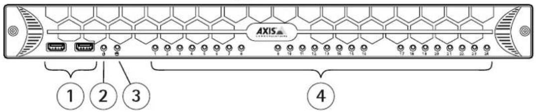
1 USB2.0connectorx2(notused)
2 SystempowerLED
3 DiskactivityLED
4 StatusLEDs, PoEport1-8, 1-16 or 1-24
BackPanelAXISCameraStationS20Series
AXIS Camera Station S2008 Appliance

AXIS Camera Station S2016 Appliance

AXIS Camera Station S2024 Appliance

1 Powerconnector
2 PoEenablednetworkconnectors,port1-8,1-16or1-24
3 U1switchuplink,RJ45connector
4 SFP1switchuplink,SFPconnector
5 U2servernetwork,RJ45connector
6 USB3.0connectorx2
7 SFP2servernetwork,SFPconnector
8 eSATAconnector
9 HDMIconnector(audiooutputsupported)
10 VGAconnector
LEDIndicators
| LEDindicator | Color | Indication |
| SystemPowerLEDSteadygreenOn | ||
| DiskactivityFlashingyellow | Read/write | |
| PoEports | Steadyred | Portconnected |

- AbouttheAXISCameraStationS20ApplianceSeries
- Setupexamples
- Managethebuilt-inswitch
- Aboutthebuilt-inswitch
- Howtoopentheswitch'swebpage
- Note
- Howtoreboottheswitch
- Important
- Howtoimprovesecurityforusedports
- Howtoimprovesecurityforunusedports
- Howtoconfiguretheswitch'slPaddress
- HowtoconfiguretheDHCPserver
- Howtoresettheswitchtofactorydefaultsettings
- Howtochangetheswitch'spassword
- Howtobackuptheswitch'ssettings
- Howtorestoretheswitch'ssettingstoppreviousbackup
- HowtoaddaVLAN
- Example
- Howtoencrypttrafficctotheswitch'swebpage
- Overviewtab
- PoEtab
- ACLtab
- VLANtab
- HTTPStab
- Networktab
- Admintab
- Productoverview
- BackPanelAXISCameraStationS20Series
Brand : AXIS
Model : S2016
Category : Video recorder