GNR-3000 - Video recorder ACTi - Free user manual and instructions
Find the device manual for free GNR-3000 ACTi in PDF.


| Product Type | Standalone Network Video Recorder (NVR) |
| Brand | ACTi |
| Model | GNR-3000 |
| Pre-installed Operating System | Microsoft Windows Embedded Standard 7 Professional |
| Pre-installed Software | ACTi NVR 3.0 (Server and Workstation Client) |
| Hard Disk Support | Up to 4 x 3.5-inch SATA hard disks (user-replaceable) |
| Maximum Managed Devices | 64 (ACTi and third-party cameras) |
| Included License | 16 channels (cumulative and perpetual, expandable via license key) |
| Network Interfaces | 2 x Gigabit Ethernet (RJ-45) |
| Video Output | VGA |
| USB Ports | USB 2.0/3.0 (for keyboard, mouse, storage) |
| Power Supply | AC adapter (included) |
| Main Functions | Live view, playback, PTZ control, event management, schedule recording, motion detection, audio support, digital zoom, snapshot, video export |
| RAID Support | Software RAID 0, 1, JBOD (via Windows Disk Management) |
| Storage Management | Assign recording drives, set reserve space, automatic deletion of oldest recordings |
| Client Access | NVR3 Workstation (local/remote), Internet Explorer (web client), mobile client (via separate app) |
| Regulatory Compliance | FCC Part 15 Class B, CE (EN 55022, EN 55024) |
| Spare Parts | Hard disks (compatible models listed on ACTi HDD Selector) |
| Repairability | User-replaceable hard disks; software upgrade via download |
| Maintenance | Disk status monitoring, volume resynchronization, system backup/restore |
Frequently Asked Questions - GNR-3000 ACTi
User questions about GNR-3000 ACTi
0 question about this device. Answer the ones you know or ask your own.
Ask a new question about this device
Download the instructions for your Video recorder in PDF format for free! Find your manual GNR-3000 - ACTi and take your electronic device back in hand. On this page are published all the documents necessary for the use of your device. GNR-3000 by ACTi.
USER MANUAL GNR-3000 ACTi
This manual is intended for System Administrators who are responsible for installing and setting up ACTi NVR 3.0 surveillance system. The reader is expected to know the fundamentals of IP surveillance system integration and to own the administrative privileges to achieve all the tasks.
You may also check http://www.acti.com/downloadcenter for updates or release information about this software and document.
Content Overview
This manual provides information needed for planning the installation, installing, setting up the system and configuring the video streaming devices. Its main content consists of the following three sections:
- Getting Started provides the preparatory knowledge you should study before starting installation, such as system requirements, license registration and backup/restore procedures.
- Log in to the System explains how to log in to the system right after a successful installation.
- System Setup gives instructions on the tasks such as adding devices to the system, configuring the device settings, scheduling the recordings, managing events, managing storage, managing groups/users and setting up Live View. For each major task, you will be given a brief introduction of operation principles, step-by-step instructions, and a simple method to check if you have done it correctly.
Related Documentation
Since this manual focuses on how to accomplish the tasks for system installation and configurations, there is very limited information about operation-wise directions for End Users who will be operating NVR server system. To obtain the instructions on use of NVR applications such as monitoring and playback, please download the latest User's Manual from ACTi Download Center http://www.acti.com/downloadcenter
Technical Support
If you have any questions during system installation, please feel free to contact our engineers via our Customer Help Desk platform http://www.acti.com/CHD.
System Integration
NVR 3.0 is supported by other products via integration tools. Please follow the instructions in the installation guide to complete the installation and system configuration.
| Tool | Installation Documentation |
| Plug-in for Lenel OnGuard | Plug-in for Lenel OnGuard Installation Guide |
You can find both the tool and its installation documentation on http://www.acti.com/downloadcenter
Conventions Used in This Manual
The following are typographic conventions used in this manual:
- Bold: Bold typeface is used for a keyword, major functions of NVR, or a title of a section/column.
- Italic: Italic typeface is used for a filename or location path.
● Underlined: Underlined typeface is used for a document name or hyperlink. - “Bold”: Bold interface enclosed in double quotation marks indicates the name of a button, a menu or a choice item.
Some notices are placed within the following boxes; each type of the box indicates different purposes or levels of importance for system:
Important Notice
The content within this box is an important notice. This notice is important for you to get certain functions to work properly, or to prevent from certain potential problems that may damage your system. Make sure you read this notice and follow the instructions.
Note
The content within this box is a note. A note is some necessary information you need to know about the action you are currently taking, like what will happen after you follow or don't follow certain procedure.
Tip
The content within this box is a tip. A tip gives you an alternative method to easily or quickly achieve an objective, usually for specific conditions.
Legal Notice
Disclaimer
- The information contained in this document is intended for general information purposes. ACTi Corporation shall not be liable for errors contained herein or for incidental or consequential damages arising from the furnishing, performance, or use of this manual.
● The information contained herein is subject to change without notice. - The English version of this document is the official one for all purposes. All the translated versions are provided as a convenience. Any discrepancies or differences created in the translations of any other languages are not legally binding.
Copyright
Copyright © 2003-2014 ACTi Corporation All Rights Reserved.
Trademarks
- ACTi Connecting Vision and its logo Corporation.

ACTi
Connecting Vision
- Microsoft® and Windows® are registered trademarks of Microsoft Corporation. All other product or company names mentioned in this document may be trademarks or registered trademarks of their respective owners.
Regulatory Compliance Information
Federal Communications Commission Statement

This equipment has been tested and found to comply with the limits for a Class B digital device, pursuant to Part 15 of the FCC Rules. These limits are designed to provide reasonable protection against harmful interference in a residential installation. This equipment generates, uses
and can radiate radio frequency energy and, if not installed and used in accordance with the instructions, may cause harmful interference to radio communications. However, there is no guarantee that interference will not occur in a particular installation. If this equipment does cause harmful interference to radio or television reception, which can be determined by turning the equipment off and on, the user is encouraged to try to correct the interference by one or more of the following measures:
- Reorient or relocate the receiving antenna.
- Increase the separation between the equipment and receiver.
- Connect the equipment into an outlet on a circuit different from that to which the receiver is connected.
- Consult the dealer or an experienced radio/TV technician for help.
WARNING: Changes or modifications to the equipment that are not expressly approved by the responsible party for compliance could void the user's authority to operate the equipment.
European Community Compliance Statement

This product has been tested and found to comply with the limits for Class B Information Technology Equipment according to European Standard EN 55022 and EN 55024. In a domestic environment, this product may cause radio interference in which cause the user be require
to take adequate measures.
Table of Contents
1 About This Manual 2
Target Audience....2
Content Overview....2
Related Documentation....3
Technical Support....3
System Integration....3
Conventions Used in This Manual....4
2 Legal Notice 5
Disclaimer....5
Copyright 5
Trademarks....5
Regulatory Compliance Information......6
3 Table of Contents 7
4 Overview 13
Product Overview....13
Server / Client Architecture 14
Client PC System Requirements....15
5 Getting Started 17
What's in the Box....17
At a Glance....18
Hard Disk Installation....19
Step 1: Remove the Tray .... 19
Step 2: Mount the Disk....20
Step 3: Install the Tray .... 20
Connect the Devices....21
Start the Unit 22
Definitions of LED Indicators ......23
Turn Off the Unit....23
Enter Windows....24
Adjust Screen Resolution 25
Get the Hard Disks Ready for Recording....26
Windows Volume Configuration 27
Windows Volume Types Comparison 28
Start Creating Disk Volumes 29
Observe Disk Status....32
Live View Screen.... 32
Disk Management 33
Trouble-shoot the Disk Drives 34
Reactivate the Disk 35
Check the Physical Connection....35
Reactivate the Volume 36
Volume Resynchronization....36
Repair the Mirrored Volume 36
Replace the Disk.... 37
Configure the IP Address 38
Find the IP Address of GNR....38
Assign a Static IP Address to GNR....39
License and Activation ....41
Online Activation 42
Offline Activation 42
Step-by-step Activation Process 43
Online Activation SOP 43
Offline Activation SOP 44
Verify Your License 45
6 Log In to the System 46
Access the NVR Server via NVR3 Workstation....46
Local Workstation Client Login 47
A. Enter Account & Password 47
B. Choose the Initial Page 47
C. Language 47
D. Remember Login Information and Auto Login 47
E. Retrieve the User Password 48
Remote Workstation Client Login 48
A. Server IP & Server Port 48
B. Enter Account & Password 48
C. Choose the Initial Page 48
D. Language 49
E. Remember Login Information and Auto Login 49
F. Retrieve the User Password 49
G. Server Name/Server Sites List 49
Access the NVR Server via Internet Explorer ....51
Accept ActiveX Controls Installation Requests 51
Log in Failure Troubleshooting 51
Condition 1: Why can't I access NVR server via web browser? 52
Condition 2: Why can't I install Active X controls after logging in? 53
Login 55
A. Enter Account & Password 55
B. Change UI language 55
C. Remember Account/Password 55
D. Retrieve the User Password 55
7 Set up the System 56
Setup Wizard....56
System Settings 57
Storage 57
NVR Main Screen....59
Live View 59
Playback....59
Setup....59
Add Devices....60
Search Devices Within Local Area Network 61
Search Devices Within Local Area Network with ONVIF 62
Add Devices on WAN or Other Local Area Networks.... 63
Basic Settings Attributes 64
Device Status....66
Status Icon Description 66
Add Non-ACTi Cameras 67
Manage Multiple Devices....69
Modify Basic Connection Settings....69
Delete Devices....69
Copy Settings Across Devices 70
Add Video Streams from a Multi-channel Device 71
Configure Device Settings....72
Configure Video Format 72
Video Settings Attributes 72
Save Storage by Setting Event Recording Frame Rate 73
Schedule Recording 73
Event Recording 73
Event Recording with Frame Rate Adjustment 74
How to Make Use of Event Recording with Frame Rate Adjustment 74
Fine-tune the Image 75
Video Adjustment Attributes 76
Configure Motion Settings.... 78
Adjustment Attributes 79
Configure Storage Card Settings 80
Configure PTZ Device....81
Adjustment Attributes 82
How to Do Live PTZ Operation 83
Set PTZ Preset Points....85
Set PTZ Preset Tour....86
Configure Fisheye Cameras....87
Schedule Recordings 91
Configure the Recording File Properties 91
Set the Schedule....93
Use Time Setting Quick Buttons to Set the Time in One Click 94
Lock Specific Days 95
Copy an Existing Schedule to Others....96
View the Entire Recording Schedule....97
Event Management....98
How Does NVR Handle Events....98
How to Edit an Event Rule 99
Manage the Event Rules.... 102
Delete the Event Rules 103
How to Setup SMTP Settings for Event Rules 103
How to Setup FTP Settings for Event Rules.... 104
System Log 106
Define Search Time .... 106
Choose Log Type 107
Read the Log 107
Export the Log 108
Storage Management 109
Change Recordings Folder Name.... 109
Set System Log Lifecycle.... 109
Set Hard Drives for the Recorded Files Deletion Rule .... 109
Manage User Groups/ Users 111
Overview 111
User Groups.... 112
Add Users 114
Domain Users Management 116
Customize Views 117
Step 1: Create a New View ...... 118
Step 2: Enter Edit Mode .... 118
Step 3: Select a Layout .... 118
Step 4: Add Video Source .... 119
Step 5: Add a Map ...... 119
Step 6: Add Devices to the Map....121
Step 7: Adjust the Channel Size & Layout.... 122
Step 8: Save the View ...... 122
Step 9: Set Default View.... 122
Step 10: Set Default Hotspot Channel (Optional).... 123
Step 11: Set Fisheye Camera Mode .... 123
Manage the Views.... 124
Set View Link 125
Set View Patrol.... 125
Tips to Enhance Live View Performance.... 127
Customize System Language....129
System Languages List.... 129
Display Configurations....132
Video & Snapshot Export Configurations 133
Joystick 134
Joystick Configurations 134
NVR System Upgrade ....135
Install the Software.... 135
Workstation Installation and Upgrade 139
Install or Upgrade the Software.... 139
Back Up System Data....141
Step 1: Back up System Settings.... 141
Step 2: Back up Recording Files Folder (Optional) ...... 142
Step 3: Back up Recording Files Index Folder (Optional)...... 142
Step 4: System Log (Optional) 142
Advanced Administrative Tasks....144
NVR Server Status....144
Change Server Port 144
Change Authentication Method.... 145
Switch to Redundancy Server....146
License Registration....146
Set up Redundancy Server....149
Overview
Product Overview
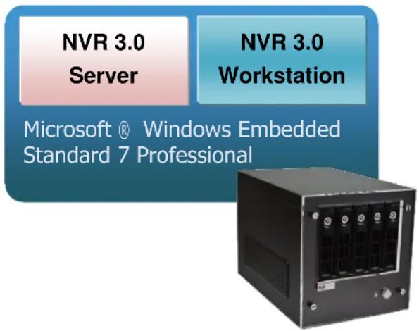
GNR-3000 is a compact and reliable multi-channel standalone NVR. It contains a pre-installed Windows operating system, and ACTi NVR 3.0 video management software along with client software.
This unit is composed of:
●Computer
A PC, with Microsoft ® Windows Embedded Standard 7 Professional operating system pre-installed.
●NVR 3.0 Server System
A video management software that allows this PC to become a server, where the system administrator performs the administrative tasks and NVR server services (event handling, schedule recording, media streaming, etc) take place.
●NVR 3.0 Client Application
The dedicated client application of NVR3 system - NVR3 Workstation, allowing the user to directly access NVR3 interface. A remote client can also access this system via network.
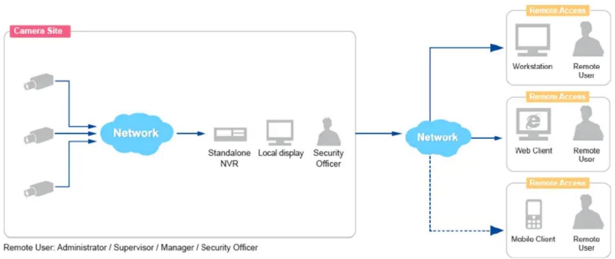
Server / Client Architecture
NVR 3.0 is a typical web-based server/client system. In a video surveillance system architecture, the Server serves as a video management service provider, aimed to run 24/7 offering non-stop services for clients. A Client makes requests of monitoring video streams or playback recordings to Server, which can reside on the same computer with server program (as from local) or on another computer (as from remote). Server starts automatically as soon as the Server computer (where it is installed) boots up, and operates in the background without requiring login by administrator. It would provide services over the TCP/IP network to multiple Clients upon request through HTTP Protocol.
There are two types of Clients in NVR 3.0 system: Web Client and Workstation Client. A user, connecting from whether web browser or workstation, will enjoy the same user interface and NVR functions.
- Web Client: the web version of interface to access NVR server without need of installing any client program to become a client. Logging in the NVR server is as simple as visiting a website through IE browser.
- Workstation Client: the client application making accessing NVR server free from the use of browser. The workstation includes a set of programs that provide interface between users and the NVR server.
flowchart
graph LR
    A["Camera Site"] --> B["Network"]
    B --> C["Standalone NVR"]
    B --> D["Local display"]
    B --> E["Security Officer"]
    C --> F["Network"]
    D --> F
    E --> F
    F --> G["Remote Access"]
    G --> H["Workstation"]
    G --> I["Remote User"]
    F --> J["Remote Access"]
    J --> K["Web Client"]
    J --> L["Remote User"]
    F --> M["Remote Access"]
    M --> N["Mobile Client"]
    M --> O["Remote User"]
Client PC System Requirements
The minimum CPU Processor spec will provide acceptable performance for systems that use mostly MPEG4 streams.
| PC Spec | Remote Client PC | ||
| Number of Live Channels (*2) | 1-16 | 17-64 | |
| CPU Processor | Minimum | Intel Core 2 Quad 2.4GHz | Intel i5 2.4 GHz |
| Recommended | Intel i5 2.4 GHz | Intel Core i7-920 2.67 GHz | |
| RAM | 4GB (*3) | ||
| Network | Ethernet (1000 Base-T recommended) | ||
| Operating System (*4) | Windows 8, Windows 7, Windows Server 2012, Windows Server 2008 | ||
| Display Resolution | Minimum: 1024 X 768 | ||
| Browser | Internet Explorer 8, 9, 10 and 11 | ||
*1 These specifications are based on following camera settings:
Single stream mode →1280x1024, 3Mbps, 18fps, MPEG-4
Dual stream mode→1280x1024, 3Mbps, 18fps, H.264 (recording);
640x480, Quality: 100, 18fps, MJPEG (live view).
*2 Live view for multiple channels requires good hardware for smooth performance. For more channels or heavy use of high resolution streaming, it is good to adopt computers with more advanced specifications than the requirements we suggest.
*3 Please use 64-bit system if your computer has more than 4GB RAM. Windows operating system has limits on memory and address space regardless of the real or virtual memory available on a particular computer. Take Windows 7 Professional for example, the maximum physical memory for a 32-bit(X86) system can address is 3.5 GB even though 16 GB of RAM has been installed on this computer. Therefore, if you consider increasing the computer's multi-tasking capability by adding more RAM, you will need a 64-bit version of Windows to take advantage of it all.
Please visit the link below for more memory limitations on various Windows platforms.
http://msdn.microsoft.com/en-us/library/aa366778%28VS.85%29.aspx#physical_memory_I
imits_windows_7
Besides the limitation mentioned above, you may find the usable memory of your computer
displayed here: Computer Properties is still less than actual installed memory.
This is a common symptoms of all Windows platforms, please find explanations and solutions in this Windows official support document http://support.microsoft.com/kb/978610/en-us and http://windows.microsoft.com/en-us/windows7/taking-the-mystery-out-of-64-bit-windows
*4 Please make sure your operating system is fully patched with the latest service packs.
Getting Started
What's in the Box
This product package includes the following items:
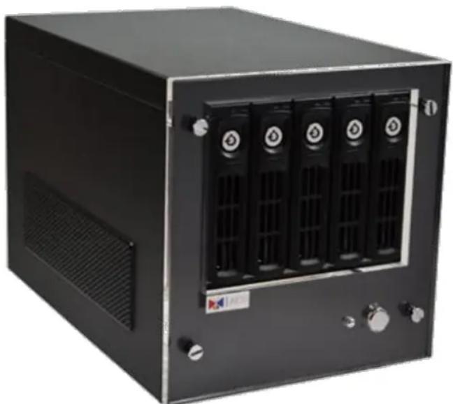
natural_image
Exterior view of a black industrial server unit with multiple drive bays and ventilation slots (no visible text or symbols)1 GNR-3000 × 1
2 Quick Installation Guide x 1
5 Power Chord x 1
(Adapter type varies by region)
3 Accessories 4 Warranty Card x 1
6 Removable Hard Disk Bays x 5 (Stored inside the unit)
At a Glance
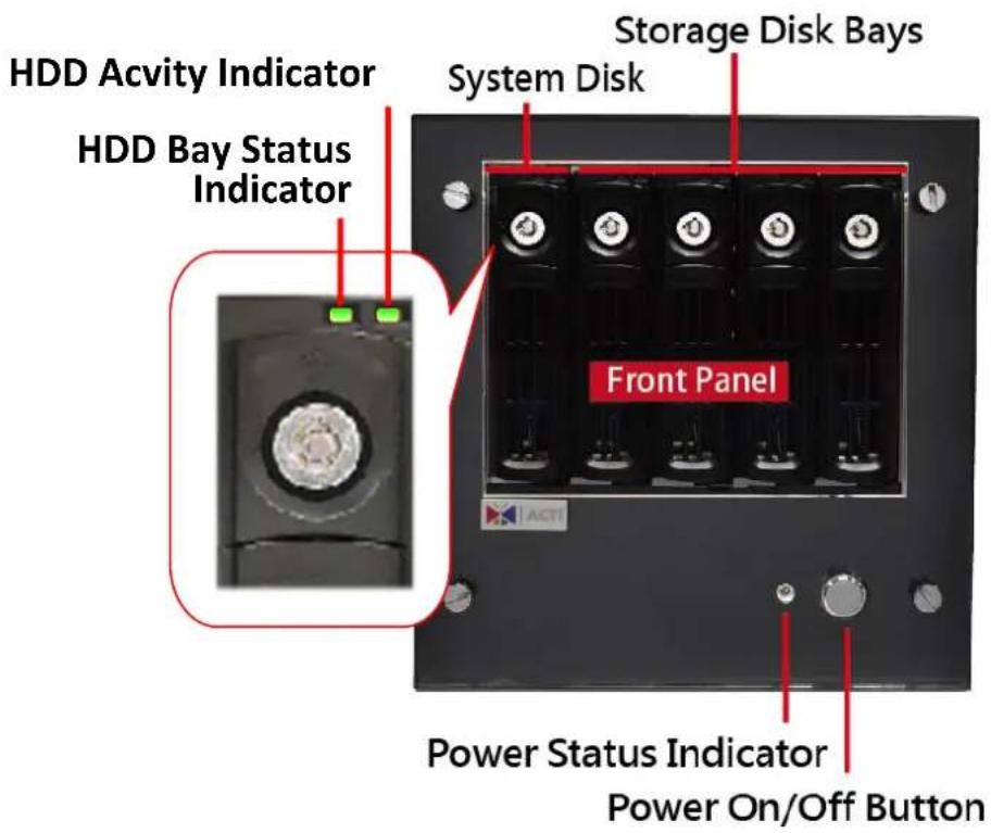
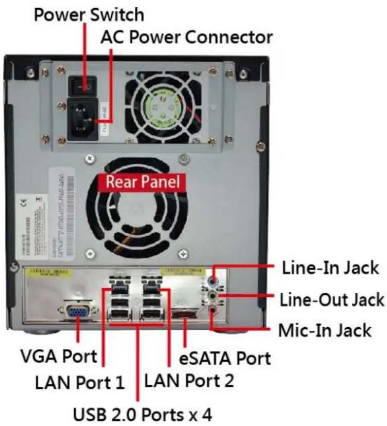
Hard Disk Installation
For video recordings, you should install at least ONE certified 3.5-inch SATA hard disk. Be sure to use the hard disk models ACTi tested to be compatible with GNR-3000, and it's strongly recommended that you use hard disks of the same model and capacity. You may find the certified models via http://www.acti.com/hddselector.
The actual necessary space depends on number of devices, recording and event rules settings. To get an approximate value, you may use the software tool Bandwidth & Storage Calculator - http://www.acti.com/storagecalculator.
You can install up to four disks into Storage Disk Bays. During the installation, please avoid removing the System Disk Bay.
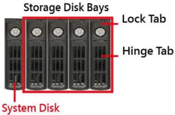
Repeat Step 1\~3 to finish installing all the storage disks. During the installation, please avoid removing the System Disk Bay.
Step 1: Remove the Tray
Slide the Lock Tab up, the Hinge Tab will pop out by itself.
Pull the Hinge Tab to 90 degrees from the front, and then pull out the tray.
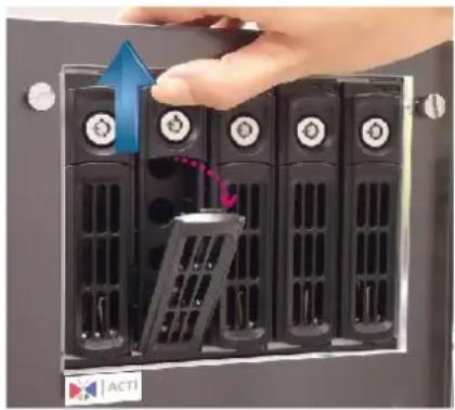
natural_image
Hand placing a device into a rack-mounted server unit (no visible text or symbols)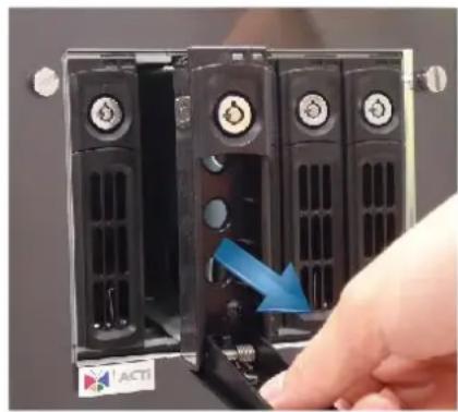
natural_image
Close-up of a hand inserting a device into a rack-mounted server unit, showing no text or symbols on the device itself.Step 2: Mount the Disk
Mount the disk by locking it with supplied disk screws to the bottom of the tray.
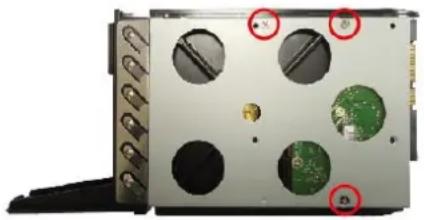
natural_image
Exterior view of a computer case with multiple circular components and a green circuit board (no visible text or symbols)Step 3: Install the Tray
Press on Lock Tab, push the tray into the bay until it stops.
Press on the Hinge Tab until it clicks into place.
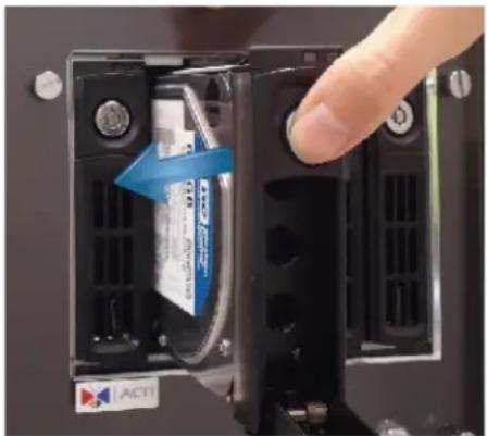
natural_image
Close-up of a hand inserting a battery into a black electronic device panel, showing internal components and a blue arrow indicating direction (no text or symbols visible)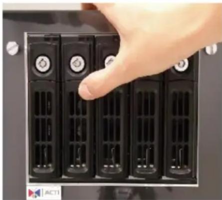
natural_image
Hand inserting a black server into five drive bays (no text or symbols visible)Connect the Devices
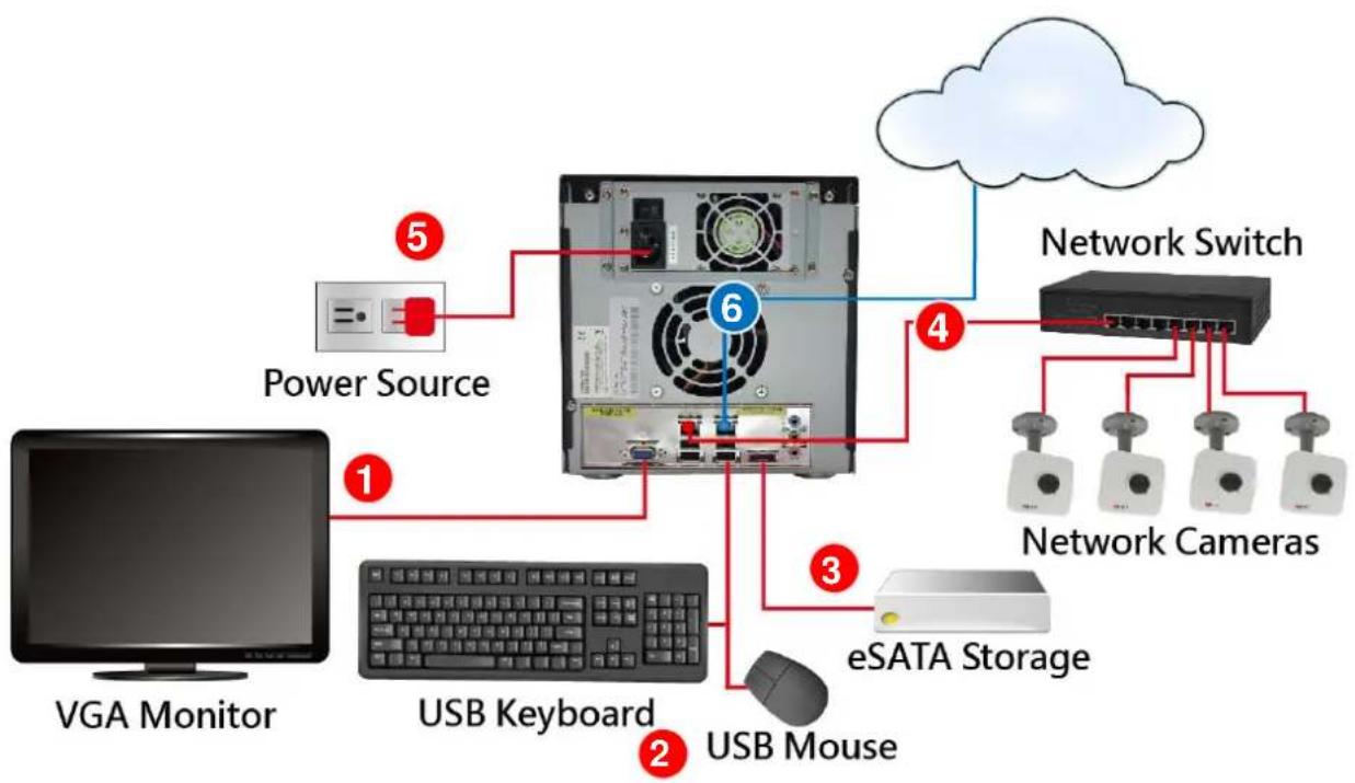
Follow the procedures to connect the devices. These devices are supposed to get connected in the sequence shown below.
flowchart
graph TD
    A["PGA Monitor"] -->|1| B["USB Keyboard"]
    B -->|2| C["USB Mouse"]
    C -->|3| D["eSATA Storage"]
    D -->|4| E["Network Switch"]
    E -->|5| F["Power Source"]
    F -->|6| G["Cloud"]
    style A fill:#000,stroke:#fff,color:#fff
    style B fill:#f9f,stroke:#333
    style C fill:#ccf,stroke:#333
    style D fill:#cfc,stroke:#333
    style E fill:#fcc,stroke:#333
    style F fill:#ffc,stroke:#333
    style G fill:#cff,stroke:#333
- Connect the VGA monitor using the VGA cable supplied by the monitor manufacturer.
- Connect the USB devices (e.g. the mouse, the keyboard or the joystick) and the audio devices (e.g. the microphone and the speaker) to the audio output and audio input.
- Connect the eSATA storage device (optional).
- Attach the network cable to one of the LAN ports.
- Plug the power adapter into GNR and electricity outlet.
- Connect GNR with another network segment (e.g. remote client connection, SMTP service) via the other LAN port (optional).
Tip
GNR-3000 supports iSCSI NAS. For detailed information on how to use iSCSI NAS with GNR-3000, please refer to our article on Using iSCSI NAS with NVR.
Start the Unit
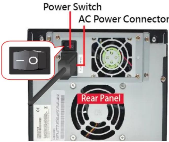
- On the rear panel, press down the Power Switch to the side with "I" mark.
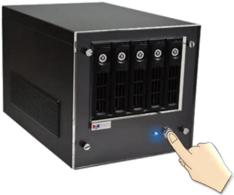
- On the front panel, press down Power Button, the Power Status LED Indicator will light up and turn solid blue.
natural_image
Illustration of a black server rack with multiple drive units and a blue indicator light, connected by a finger to the right (no text or symbols visible)Definitions of LED Indicators
| Indicator | LED Status | Description |
| Power Status | Solid | The unit power is on. |
| HDD Bay Status | Solid | The hard disk is installed and detected in this bay. |
| HDD Activity | Flashing | There is read or write activity. |
Turn Off the Unit
The unit can be turned off by the methods described below, and the Power Status LED Indicator will go off right after the device is turned off.
natural_image
Close-up of a black industrial electrical switch panel with six buttons and a finger pointing to it (no visible text or symbols)- Shut down the system from Windows Start

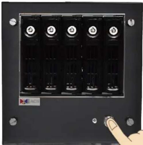
- Press down Power Button to turn the device off.
To completely cut off the power supply of this unit, press down the Power Switch to the side with "O" mark.
Enter Windows
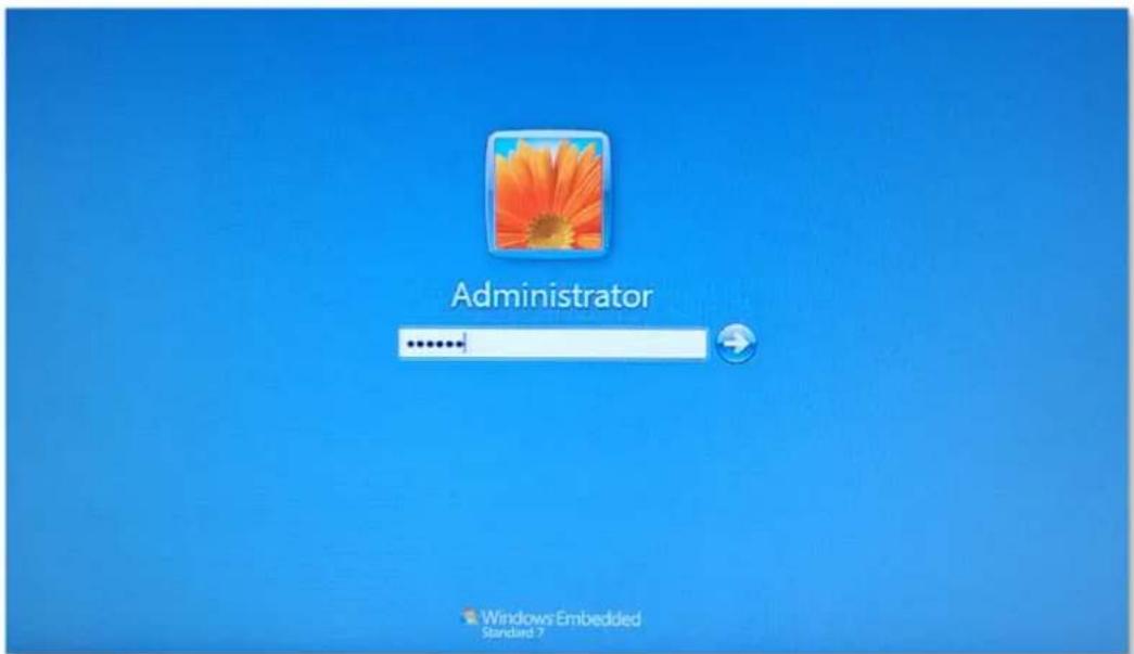
After the unit starts, key in "123456" to log in as Administrator to Windows Embedded 7 system.
Adjust Screen Resolution
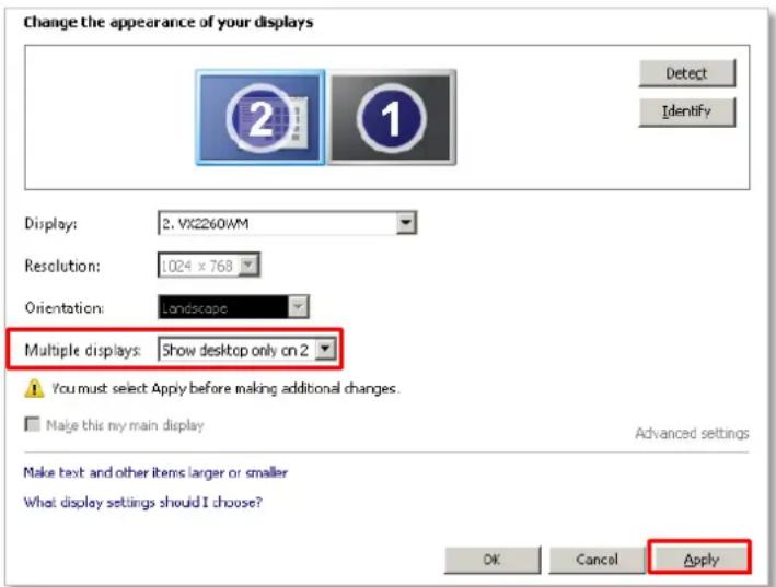
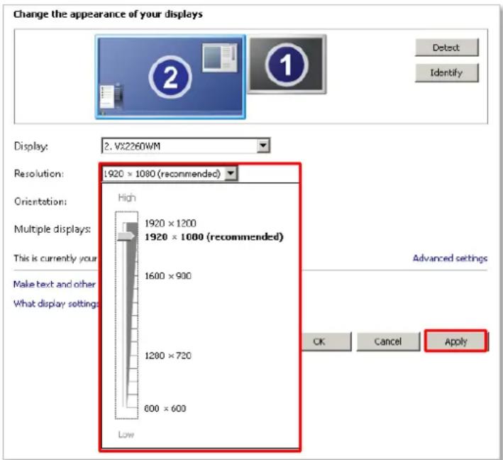
The native (maximum) resolution of GNR's built-in graphic card is 1920x1200. By default, GNR will display a lower resolution which best suits a standard 4:3 screen monitor, at which you get to see larger icons and text but the edges are not so sharp. For a wide screen or higher resolution, please modify the settings below:
- On Windows Desktop, right-click on the screen and then select Screen Resolution. Change Multiple displays setting to "Show desktop only on 2" and then apply this setting.
- On Screen Resolution window, you may now select a desired resolution size from Resolution dropdown list.
Get the Hard Disks Ready for Recording
GNR supports flexible storage system of up to four hard disks. Thanks to the built-in software RAID (Redundant Array of Independent Disks) provided by Windows Embedded 7 operating system, the installed hard disks can be configured to one or more arrays for the following benefits:
●The hard disks can appear as a one single volume of large storage size.
- User gets to define how the data is stored regarding data protection against the physical failure of one or more hard disks.
- Increase the speed of writing and reading data.
The software RAID task of Windows runs on the computer's CPU, requiring no extra hardware attached to the computer, which saves you considerable cost and effort on installation. In addition, as Windows configures the arrays at the disk volume level, a disk is not necessary to serve only one array, and you can make full use of its unmatched disk space to make another array.
There are several types of software RAID configurations available in Windows, and it is good to know whichever RAID type is suitable for your system. After reading through this chapter, you will be able to choose suitable RAID type for your video surveillance project and get the storage disks ready for recording.
Please note that, Windows refers to a single accessible storage file system as Volume instead of RAID, and the creation of software RAIDs is carried out during the process of making volumes. When you make the volumes with Disk Management utility (please refer to Start Creating Disk Volumes on page 28), your selection of Volume Type will correspond to a specific RAID type.
Windows Volume Configuration
| RAID Type | Windows Volume Type | Description | |
| -- | Simple Volume | It is the most basic method to make the available space on a single disk a volume; you can create more than one volumes on a single disk to make the most use of the disk capa.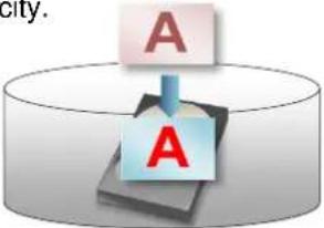 | |
| -- | Spanned Volume | This volume type is also called JBOD (Just a Bunch of Drives), combing multiple disks into a single logical volume. This method does not offer any advantage in terms of reading/writing speeds, parity, or redundancy, but sacrifices no disk space because the total storage equals to the sum of each individual disk's storage. However, since the data is written to the physical disks sequentially, any failure of a single disk is likely to fail the whole array.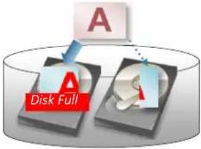 In the example, a piece of informaon is being wrien to a JBOD. Aer the rst disk is full, the rest of this data will then be wrien to the next disk. In the example, a piece of informaon is being wrien to a JBOD. Aer the rst disk is full, the rest of this data will then be wrien to the next disk. | |
| Raid 0 | Striped Volume | This configuration combines two or more disks as a single logical volume without using any parity and redundancy. However, this method highly increases the writing/reading speeds by equally splitting the data into all the disks, which means that the more disks you have in this RAID, the faster the data reading and writing will be.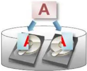 In the example, there are two disks combined into one RAID 0 array, a piece of informaon is rst split into two data blocks and then wrien to both disk at the same me. In the example, there are two disks combined into one RAID 0 array, a piece of informaon is rst split into two data blocks and then wrien to both disk at the same me. | |
| RAID 1 | Mirrored Volume | This method is RAID 1, designed to make a mirror copy of one disk on the other disk, which requires exactly two disks of the same size. Since the second disk is used as a mirror, there is no improvement in writing speed or capacity compared to a single disk scenario.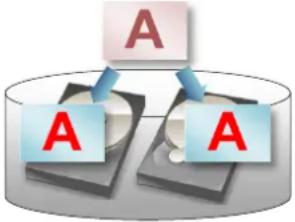 In the example, a copy of the enre data is respectively written to both disks running under RAID 1.; a piece of informaon is rst split into two data blocks and then written to both disk at the same me. In the example, a copy of the enre data is respectively written to both disks running under RAID 1.; a piece of informaon is rst split into two data blocks and then written to both disk at the same me. | |
For more details about the volume types and volume management, please refer to http://technet.microsoft.com/en-us/library/cc737098(v=ws.10).aspx
Windows Volume Types Comparison
- For the pursuit of data redundancy, which can recover all the recordings after one disk fails, it is suggested that you make a Mirrored Volume out of two disks of large capacity.
- If there are quite a few high-megapixel live channels in your system, with one or more clients frequently accessing Live View and Playback, you may consider making a Striped Volume that provides the maximum possible capacity with high performance but no failure tolerance.
The table below is based on the available configurations of GNR.
| Volume Type | Simple | Spanned | Striped | Mirrored |
| Corresponding RAID Type | JBOD | RAID 0 | RAID 1 | |
| Minimum Number of Disks required | 1 | 2 | 2 | 2 |
| Capacity | V | V_1 + V_2 +... + V_N | V_min × N | V_min |
| *Storage Efficiency | ★★★★★ | ★★★★★ | ★★★★★ | ★★* |
| Fault Tolerance | None | None | None | ★★★★ |
| Write Speed | ★★* | ★★* | ★★★★★ | ★★* |
| Read Speed | ★★* | ★★* | ★★★★★ | ★★★ |
●N = the number of disks
●V= the disk capacity ( V_min = the capacity of the disk with the smallest storage in the array)
(*)This result is obtained based on the assumption that the disks are of the same capacity.
GNR-3000 System Administrator's Manual
Start Creating Disk Volumes
- Click Windows Start , in Windows Search Box, input "Computer Management", and enter this utility.
Select "Disk Management", right-click on a disk title and select "Initialize Disk", check all the disks you have installed and choose "GPT" as the partition type, then click "OK".
- Right-click on a disk title again, and then select "Convert to Dynamic Disk...", select all the disks you installed and click "OK".
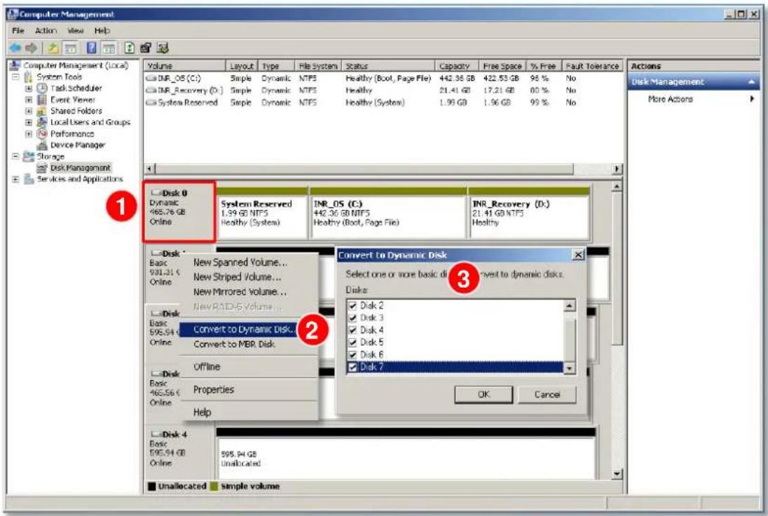
- Right-click on a disk and select the volume type to make a new volume.
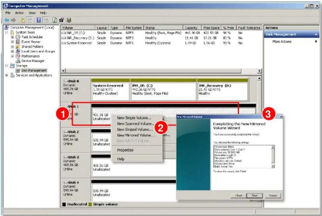
A Volume Wizard will come up to bring you thorough the configuration process. Make sure you assign the desired Drive Letter and Volume Label to this volume via the wizard.
Repeat this step to finish creating all the volumes you need.
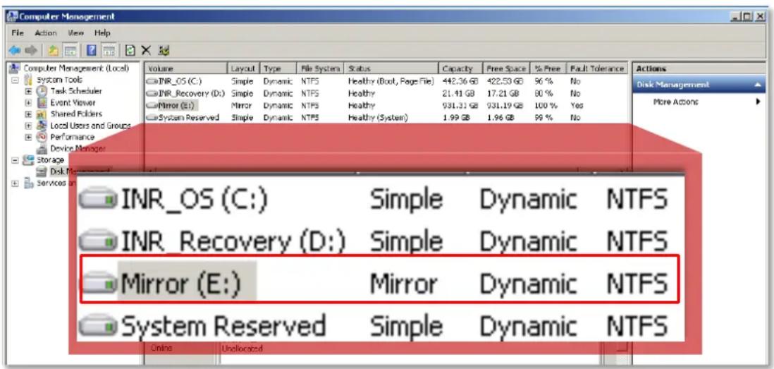
- After the volume is created, this drive will be shown on Volume list, which is ready for recording. You may follow the instructions in Storage Management on page 109 to assign certain volumes to do the recording.
Observe Disk Status
It may happen that one of your disks goes into failed status after NVR system started recording for a long period. Mostly, a disk does not fail all of a sudden but because the number of bad sectors on it has exceeded the minimum required level to maintain normal operation. On NVR Live View interface, the recording status and system events can help you make an initial assessment of the overall disk condition. For further inspection and disk management, please make use of Window 7 built-in utility- Disk Management.
Live View Screen
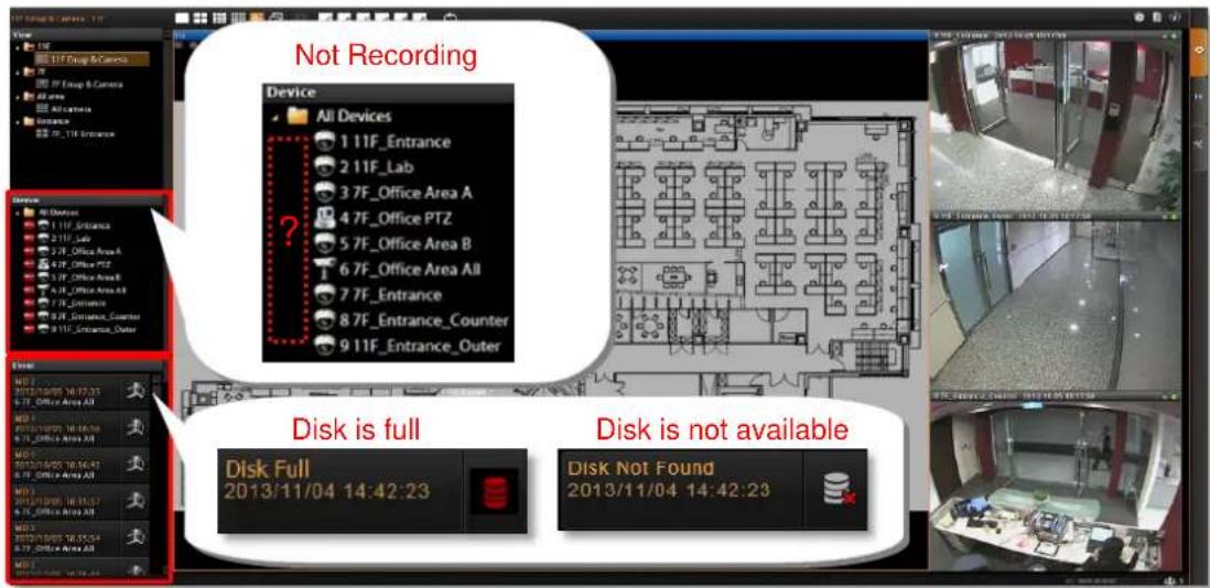
- On Device list, if the recording is proceeding normally, the red "recording" icon will appear next to the device icon. If all the icons are missing when NVR is supposed to perform schedule recording, your storage disk might have gone into abnormal status.
●On the Event list will also display two kinds of abnormal disk status
- Disk Full: The storage drive is full, recording has stopped.
- Disk Not Found: The storage disk drive has failed or disconnected.
If you encounter any abnormal condition stared above, take the following steps to make a simple diagnosis:
1. Confirm the schedule-recording setting
Go to Setup page → Schedule tab, and modify the recording schedule if it was not set correctly.
2. Check Disk Drive List
Go to Setup page → Storage tab.
- If the disk drive is missing from Disk Drive List, please refer to Trouble-shoot the Disk Drives on page 34 to fix this drive.
- If the disk is full, a warning icon will appear next to the Drive, please follow the instructions in Set Hard Drives for the Recorded Files Deletion Rule on page 109 to configure
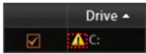
the recording rule setting. NVR will start recording again after the new setting is applied.
Disk Management
The Disk Management built-in Windows 7 is the basic management utility used for performing main storage-related tasks including managing the volumes and the disks.
Go to Windows Control Panel → Administrative Tools → Computer Management and select "Disk Management". Check the Volume list for the status of each volume, and check Disk list below for detailed individual disk status. The Volume list represents the status of your recording drive; while the status of the disks contained in this volume is shown on the Disk list below. For the explanations of different Volume status, please refer to the online help document provided by Microsoft TechNet
http://technet.microsoft.com/en-us/library/cc739417(v=ws.10).aspx, or refer to http://technet.microsoft.com/en-us/library/cc771775.aspx for coping with different disk status.

Trouble-shoot the Disk Drives
Normally, the status of a working volume appears "Healthy".
| Volume | Layout | Type | File System | Status | Capacity | Free Space | % Free | Fault Tolerar |
| Spanned | Dynamic | Failed | 1527.2... | 1527.25... | 100 % | No | ||
| □ INR_OS (C:) | Simple | Dynamic | NTFS | Healthy (Dock, Page File) | 442.36 GB | 422.53 GB | 95 % | No |
| □ INR_Recovery (D:) | Simple | Dynamic | NTFS | Healthy | 21.41 GB | 17.21 GB | 80 % | No |
| □ Mirror (E:) | Mirror | Dynamic | NTFS | Resynching | 931.31 GB | 930.97 GB | 100 % | Yes |
| □ RAID 0 (G:) | Striped | Dynamic | NTFS | Healthy | 700.58 GB | 700.57 GB | 100 % | No |
| □ Small DOD (H:) | Spanned | Dynamic | NTFS | Healthy | 594.37 GB | 594.27 GB | 100 % | No |
| □ System Reserved | Simple | Dynamic | NTFS | Healthy (System) | 1.99 GB | 1.96 GB | 99 % | No |
This chapter will provide simple guidelines for dealing with most-happening abnormal volume issues.
| Volume Status | Possible Cause | Solution |
| The volume is in Healthy (at Risk) status | Windows has found some bad sectors on its underlying disk. | Run a diagnostic check using the disk manufacturer's software tool, back up the data on this disk, and replace it with a new one as soon as possible.→Replace the Disk |
| The volume is in Failed status | One of the underlying disks has gone abnormal, which led to the failure of this volume; this also indicates data loss, meaning there is no way to recover the recordings not saved during this period, | 1. Make sure the all the disks are in Online status.→Reactivate the Disk→Check the Physical Connection→Replace the Disk2. After all the disks are Online, this volume should return Healthy. If not, try to reactivate it manually.→Reactivate the Volume |
| The Volume is in Failed Redundancy status | One of the disks in a mirrored volume has failed; the recording is still ongoing though this volume is currently not fault tolerant. | 1. Make sure the underlying disks are all Online.→Reactivate the Disk→Check the Physical Connection→Repair the Mirrored Volume2. After the disk returns to Online, this volume should start repairing itself by resynchronizing→Volume Resynchronization3. If this volume is still in Failed Redundancy status, try to reactivate it manually.→Reactivate the Volume |
More instruction about trouble-shooting provided by Microsoft TechNet:
http://technet.microsoft.com/en-us/library/cc787481(v=ws.10).aspx#BKMK_7
http://technet.microsoft.com/en-us/library/cc737098(v=ws.10).aspx
Reactivate the Disk
When the disk appears Online (Errors), Offline, Unreadable or Missing, try this step to bring this disk back to Online status. On Disk list, righ-click on the underlying disk that does not appear Online, and select "Reativate Disk".
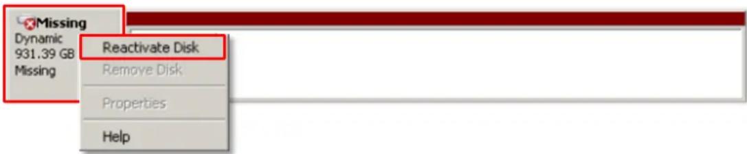
You may refer to the online help document provided by Microsoft TechNet for more details - http://technet.microsoft.com/en-us/library/cc786948(v=ws.10).aspx
If this step failed to return the disk to Online status, please Check the Physical Connection.
Check the Physical Connection
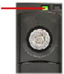
The abnormal status: Online (Errors), Offline, Unreadable or Missing) might result from the physical disconnection from the bay. Observe the front of the disk tray, if the HDD Status LED is not lit, turn off the unit, install the disk again following the steps in Hard Disk Installation on page 19, and check the disk status in Disk Management.
HDD Bay Status Indicator
natural_image
Close-up of a black rectangular object with a circular recess and a red indicator line (no visible text or symbols)You may refer to the online help document provided by Microsoft TechNet for more details- http://technet.microsoft.com/en-us/library/cc785259(v=ws.10).aspx
If this step failed to return the disk to Online status, please Replace the Disk.
Reactivate the Volume
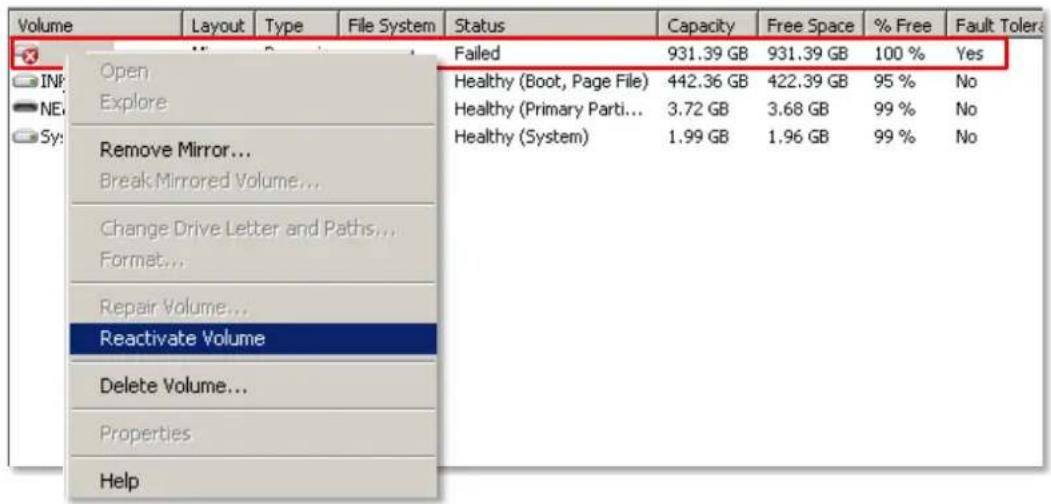
If the volume remains in Failed status even though all the underlying disks are Online, you may try manually reactivate this volume. On Volume list, right-click the volume and select
"Reactivate Volume".
Volume Resynchronization
A mirrored volume will automatically start resynchronizing to ensure that two mirrors have the identical data. The mirrored volume's status will return to Healthy after the resynchronization is done. When the volume appears in Resynching status, please avoid making any change to this mirror and the disks.
| Volume | Layout | Type | File System | Status | Capacity | Free Space | % Free | Fault Tolerance |
| INR_OS (C:) | Simple | Dynamic | NTFS | Healthy (Boot, Page File) | 442.36 GB | 422.39 GB | 95 % | No |
| Mirror (E:) | Mirror | Dynamic | NTFS | Resynching : (33%) | 931.39 GB | 931.20 GB | 100 % | Yes |
| NEW VOLUME (I:) | Simple | Basic | FAT32 | Healthy (Primary Parti... | 3.72 GB | 3.68 GB | 99 % | No |
| System Reserved | Simple | Dynamic | NTFS | Healthy (System) | 1.99 GB | 1.96 GB | 99 % | No |
Repair the Mirrored Volume
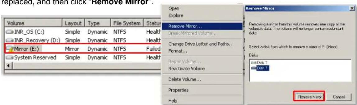
To repair a mirrored volume, replace the failed disk with a new one.
- On Volume list, right-click the volume and click "Remove Mirror...," select the disk to be replaced, and then click "Remove Mirror".
- Remove the failed disk from the bay and install a new one, following the steps in Hard Disk Installation on page 19.
- The mirrored volume has now become a simple volume. Right-click on this volume and select "Add Mirror...," select the new disk and then click "Add Mirror".
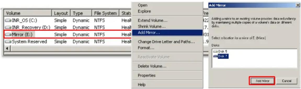
- This volume will start Volume Resynchronization immediately. During this period, the recording will proceed normally. The status will turn Healthy after the Resyching is complete.
| Volume | Layout | Type | File System | Status | Capacity | Free Space | % Free | Fault Tolerance |
| INR_OS (C:) | Simple | Dynamic | NTFS | Healthy (Boot, Page File) | 442.36 GB | 422.53 GB | 96 % | No |
| INR_Recovery (D:) | Simple | Dynamic | NTFS | Healthy | 21.41 GB | 17.21 GB | 80 % | No |
| Mirror (E:) | Mirror | Dynamic | NTFS | Resvnching | 931.31 GB | 931.00 GB | 100 % | Yes |
| System Reserved | Simple | Dynamic | NTFS | Healthy (System) | 1.99 GB | 1.96 GB | 99 % | No |
Replace the Disk
To replace a failed disk:
- On Disk list, right-click the failed disk and select "Offline".
- Shut down this unit and install the new disk following the steps in Hard Disk Installation on page 19.
- After restarting this unit, enter Disk Management, right-click on the failed volume and select "Delete Volume". For how to delete the volume using the command line, you may refer to http://technet.microsoft.com/en-us/library/cc780763(v=ws.10).aspx provided by Microsoft TechNet for more details.
- After the, volume is deleted, you may now build a new volume using the available disks.
Configure the IP Address
After GNR starts, the network interface cards in it will be assigned IP addresses with the DHCP service in the network.
Find the IP Address of GNR
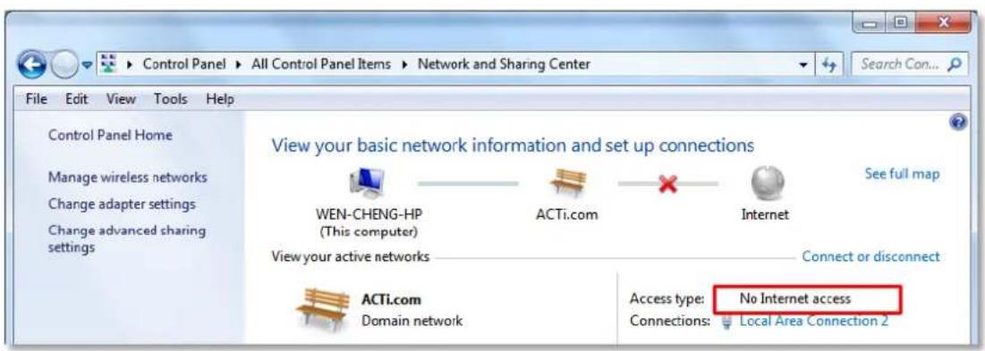
To check the current IP address assigned by DHCP service:
- Click Windows Start menu and select "Control Panel".
- Enter "Network and Sharing Center", select the network card connection. Click your current Internet connection.
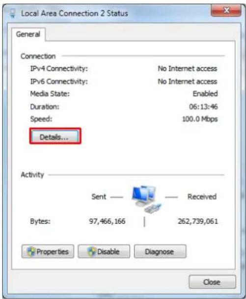
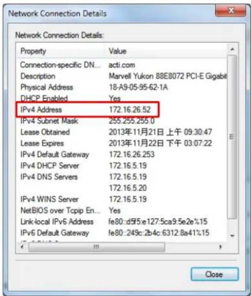
- A Connection Status window will pop up, click "Details...", you will find all the connection properties of this current network adapter in the details, including you IP address – IPv4 Address.
Assign a Static IP Address to GNR
- Click Windows Start menu and select "Control Panel".
- Enter "Network and Sharing Center", select the network card connection.
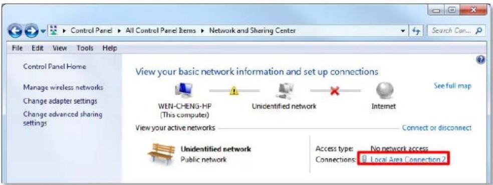
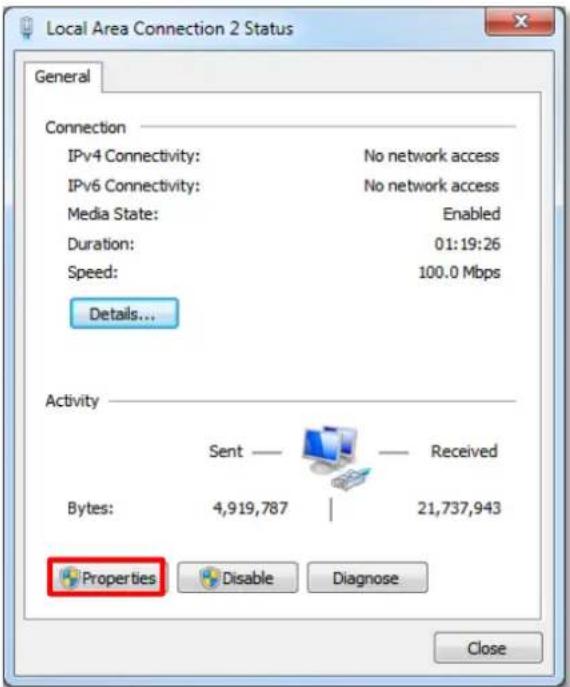
3. On Connection Status window, click "Properties
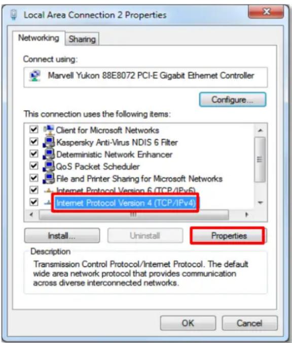
- Select "Internet Protocol Version 4 (TCP/IPv4)" and then click "Properties".
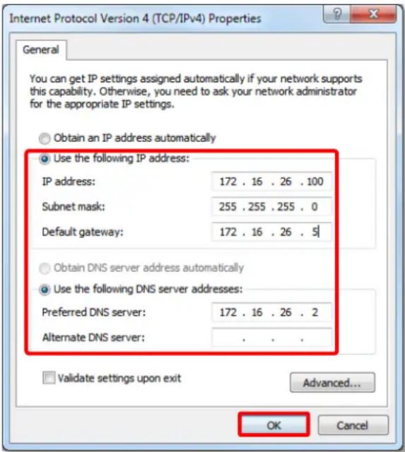
- On Properties window, select "Use the following IP address:" and enter the appropriate values for the static IP address. Click "OK" to save the settings.
- To change the current port number from 80 to another, please refer to Change Server Port on page 144.
GNR-3000 System Administrator's Manual
License and Activation
In GNR, your required number of channels should be licensed and activated before connecting the devices. The License Key, provided by ACTi sales representative once your purchase of license is carried out, will be used to activate the license. After the license activation, the channels on NVR server will automatically become available.
Aside from ACTi brand devices, NVR 3.0 system is able to support other vendors' devices. ACTi brand devices and non-ACTi brand devices are licensed by different license types:
- Standard License: ACTi brand devices
- CDP License: Other vendors' devices
(For supported non-ACTi cameras list, please refer to http://www.acti.com/3rdpartycamera)
Please note:
☐ The license is cumulative and perpetual.
The license is not version-specific; upgrading software version will not influence the existing license you have activated on NVR 3.0 server.
☐ The number of CDP-licensed channels (for non-ACTi brand cameras) and that of standard-licensed channels (for ACTi devices) are counted separately.
☐ Any device added through ONVIF (either ACTi or non-ACTi devices) will also need to be licensed. The license type used will solely be based on the brand of the device.
☐ The maximum number of devices (ACTi brand + non-ACTi brands) that can be managed by NVR 3.0 server is 64.
☐ After activating CDP license, please follow the instructions in Add Non-ACTi Cameras on page 67 to manually add those non-ACTi cameras to NVR system.
License activation is the process of unlocking the channels on NVR interface with the received License Key. License Key is a serial number delivered as a printed card or an E-mail after the purchase is carried out.
During license activation, your License Key is matched against the MAC address of the Network Interface Card (NIC) on NVR server computer. Once this license key is used by the computer with given MAC, it cannot be activated with another MAC. This matching record will be stored on the ACTi license data server. If your computer has more than one network cards, NVR server will detect them and provide you a dropdown list to select from.
Note
Although certain fisheye camera view modes (e.g. Quad mode) display multiple regions in a view, they are still counted as one single channel in terms of licensing.
There are two ways to activate the licenses depending on your GNR network condition: Online Activation and Offline Activation.
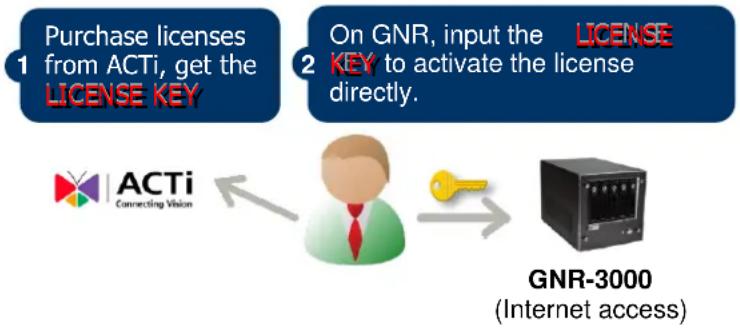
Online Activation
If your GNR has available Internet access, choose online activation.
flowchart
graph TD
    A["1 Purchase licenses from ACTi, get the LICENSE KEY"] --> B["2 On GNR, input the LICENSE KEY to activate the license directly."]
    B --> C["↓"]
    C --> D["→ GNR-3000 (Internet access)"]
    E["ACTi Connecting Vision"] --> C
Offline Activation
Offline activation does not require Internet access GNR. It is used when GNR is located in network not connected to public Internet (e.g. in a military base). You will need to get an activation file from another computer and transfer it to GNR.
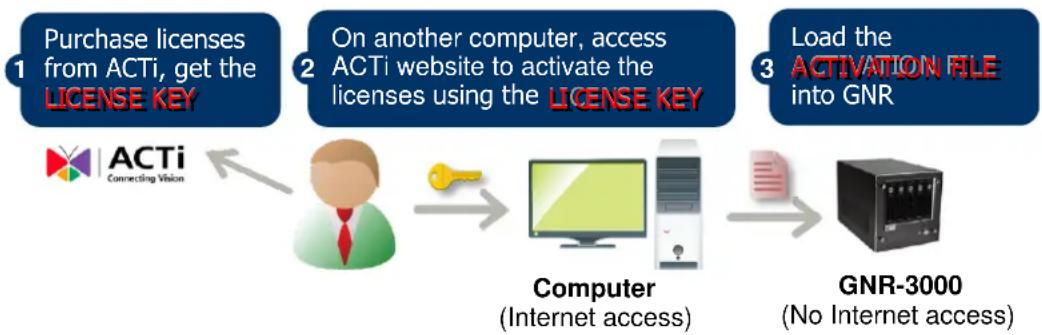
flowchart
graph LR
    A["1 Purchase licenses from ACTi, get the LICENSE KEY"] --> B["2 On another computer, access ACTi website to activate the licenses using the LICENSE KEY"]
    B --> C["3 Load the Activation File into GNR"]
    C --> D["4 Computer (Internet access)"]
    D --> E["5 GNR-3000 (No Internet access)"]
Step-by-step Activation Process
Based on the network conditions of your site, follow Online Activation SOP or Offline Activation SOP to activate your license.
Online Activation SOP
Step 1: Membership ID in ACTi Member Center is required for activation. Register one for free at http://member.acti.com/
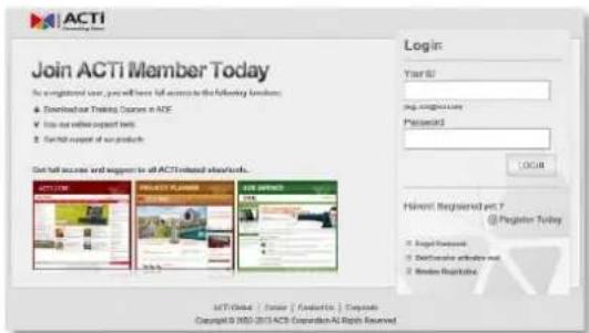
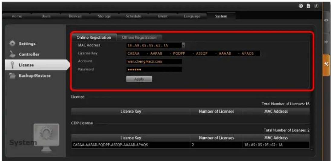
Step 2: Log in NVR server, go to Setup page→System tab→License→“Online Registration”. Select the MAC Address, enter your License Key, ACTi member Account and Password, and then click “Apply”. NVR server will connect to the license data server via Internet to register the license key, and unlock the channels.
Offline Activation SOP
Step 1: Membership ID in ACTi Member Center is required for activation. Register one for free at http://member.acti.com/
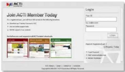
Step 2: Access http://www.acti.com/support/LicenseMgt/NVR3_registration.asp, enter the License Key and the MAC address of NVR server computer, and click "Submit". An e-mail with activation code file (.lic) will be sent to your registered E-mail account.
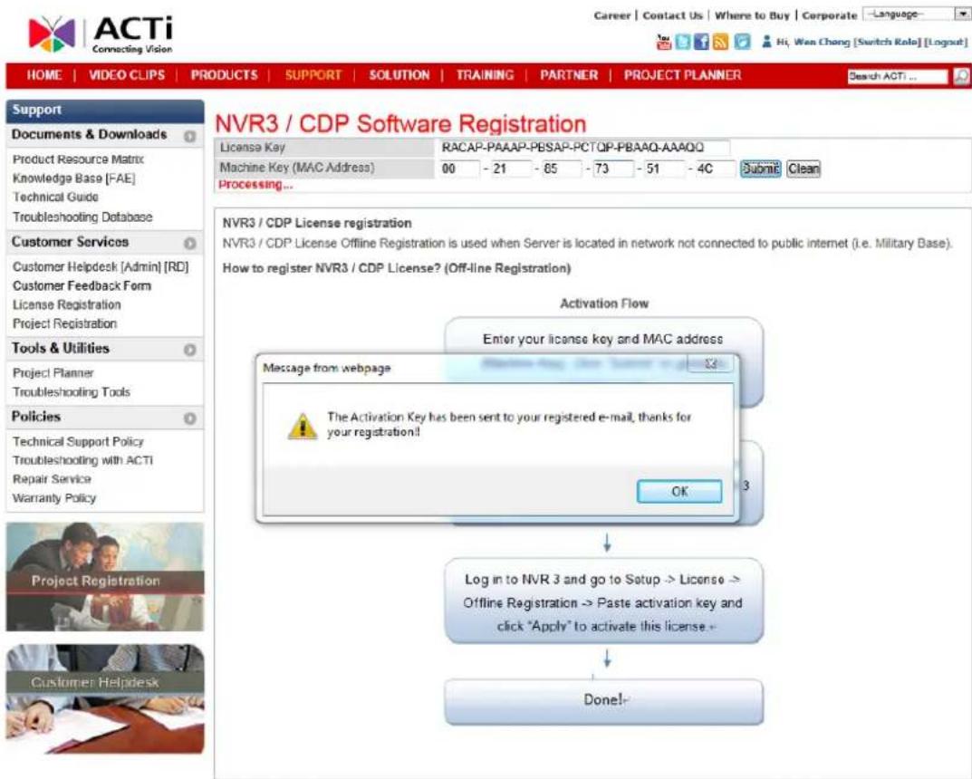
Step 3: Log in NVR server from local or via web client. Go to Setup page→System tab→License → "Offline Registration"→ click "Import" and upload the license file (.lic). Click "Apply" to activate this license.
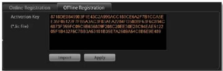
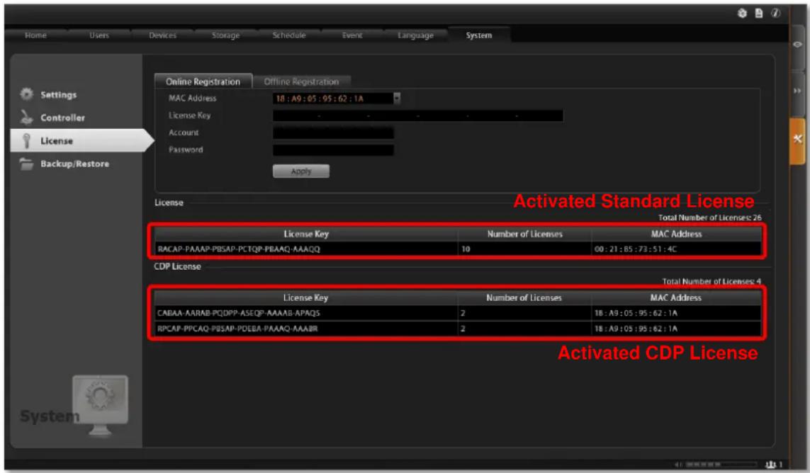
Verify Your License
Once your license is successfully activated, the license information will be shown on License page.
Important
The license data will be erased once NVR 3.0 server is uninstalled. Be sure to retain your license key information in a safe place because you may need to reinstall the software. After the software is uninstalled, you should contact ACTi Customer Help Desk http://www.acti.com/CHD to clear the original registration data in our data server, and then you may activate the license again.
Tip
How to find MAC Address
- Click Windows Start, in the run box on Start menu, input "cmd".
- Execute the cmd program, and input the command "ipconfig /all" or "getmac"
- The MAC address will be referred to as the Physical Address, made up of 12 characters e.g. 00-1E-65-FE-8E-98
Log In to the System
Access the NVR Server via NVR3 Workstation
NVR3 Workstation includes a set of programs that provide the interface between users and the NVR server. In GNR, this software is already installed, and will start automatically after you login to Windows. You can also install this software on the
remote client computer to access the NVR server via network. You can download this software on ACTi website at http://www.acti.com/product/download, and it is wrapped together with the NVR 3.0 system software. For the instructions on the installation of this software on the client computer, please refer to Workstation Installation and Upgrade on page 139.
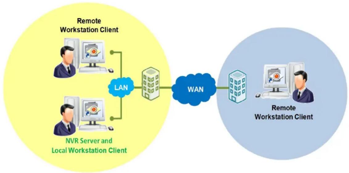
flowchart
graph LR
    A["Remote Workstation Client"] --> B["NVR Server and Local Workstation Client"]
    B --> C["LAN"]
    C --> D["WAN"]
    D --> E["Remote Workstation Client"]
Local Workstation Client Login
Local Workstation Client refers to the user who runs NVR3 Workstation on the NVR server to log in to the NVR system. The login process is described as follows.
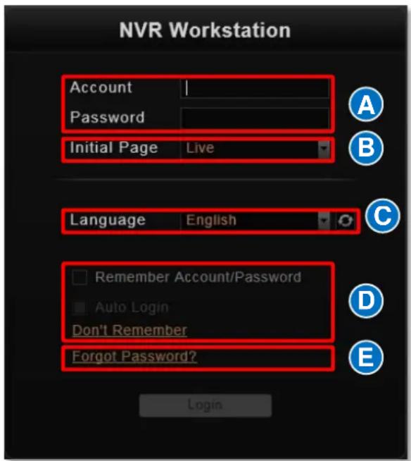
A. Enter Account & Password
Account (non case-sensitive)
Admin (default)
Password (case-sensitive)
123456 (default)
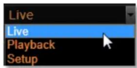
B. Choose the Initial Page
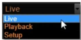
The user interface consists of three main module screens, Live View, Playback and Setup. You may choose one where
you would like to enter after login. Default is Live View screen.
C. Language
Choose a UI language from the dropdown list.
D. Remember Login Information and Auto Login
To have NVR3 Workstation remember the Account, Password, Initial Page and UI Language, simply check "Remember login info". Click "Don't Remember" will clear your input text and reset to default. If the NVR server or remote client computer may be accessed by someone else, you might consider not to use this function.
To automatically login to the NVR system, please check both "Remember login info" and "Auto Login" to skip the Login page. If the NVR server or remote client computer may be accessed by someone else, you might consider not to use this function.
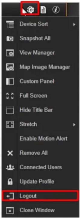
To cancel auto-login, on title bar, click → "Logout" to return to login page, and this function will be cancelled.
E. Retrieve the User Password
The NVR server can send the password of the User's account to the saved email address. To have users be able to use this service, please make sure (1) the SMTP settings have been configured (refer to How to Setup SMTP Settings for Event Rules on page 103) and (2) a valid email address has previously been saved in Setup page → Users tab → User list.
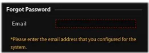
The email address input in Forgot Password window should match the one under your User account saved in the NVR server.
Remote Workstation Client Login
Remote Workstation Client refers to the user who runs NVR3 Workstation on a computer rather than the NVR server, and tries to reach the NVR server via network. The login process is described as follows.
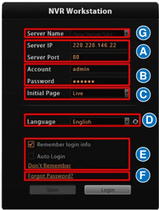
A. Server IP & Server Port
In Server IP field, please input the LAN or WAN IP address of the NVR server.
In Server Port field, key in the port number. The default value is 80.
B. Enter Account & Password
Account (non case-sensitive)
Admin (default)
Password (case-sensitive)
123456 (default)
C. Choose the Initial Page
The user interface consists of three main module screens, Live View, Playback and Setup. You may choose one where you would like to enter after login. Default is Live View screen.
D. Language
Choose a UI language from the dropdown list.
E. Remember Login Information and Auto Login
To have NVR3 Workstation remember the Account, Password, Initial Page and UI Language, simply check "Remember login info". Click "Don't Remember" will clear your input text and reset to default. If the NVR server or remote client computer may be accessed by someone else, you might consider not to use this function.
To automatically login to the NVR system, please check both "Remember login info" and "Auto Login" to skip the Login page. If the NVR server or remote client computer may be accessed by someone else, you might consider not using this function.
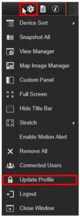
To cancel auto-login, on title bar, click → "Logout" to return to login page, and this function will be cancelled.
F. Retrieve the User Password
Please refer to E. Retrieve the User Password on page 48
G. Server Name/Server Sites List
NVR3 Workstation can remember multiple server sites and their login settings and show the site lists on Login window. To add a new site:
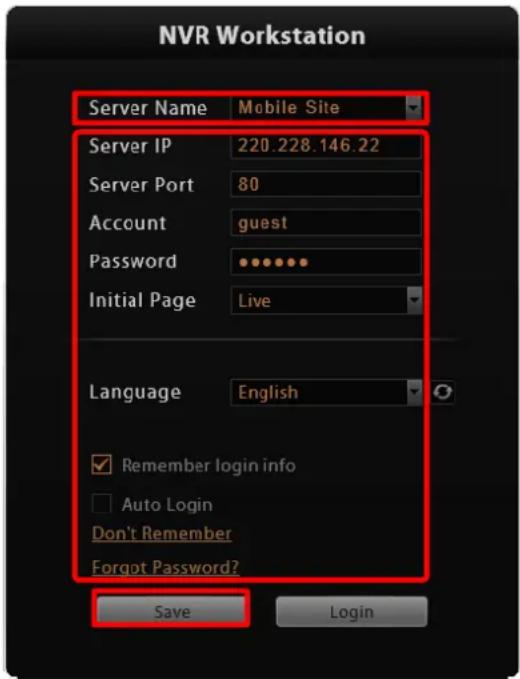
- Click in the Server Name box and input the server site name.
- Fill in the other fields. If you disable the "Remember login info", then only the Server Name, Server IP and Server Port of this server site will be remembered.
- Click "Save".
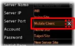
- After a server site is saved, it will be shown on Server Name dropdown list.
You may click on its name to enter its Login window or ✗ to delete it from the list.
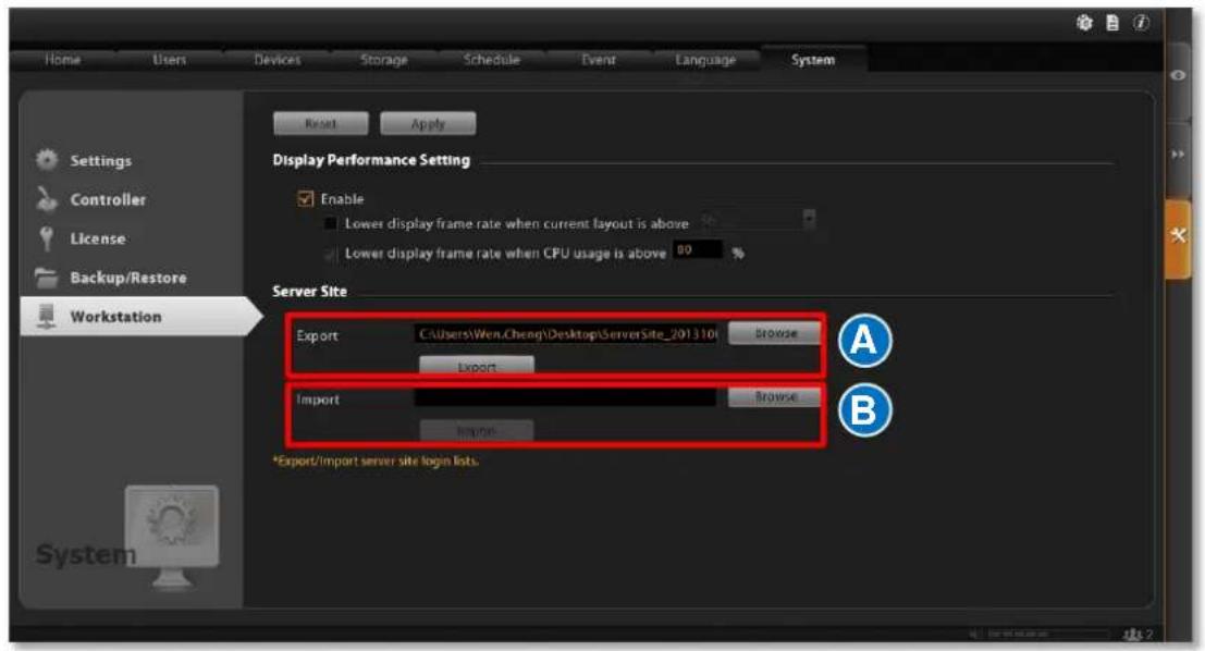
- You can export the saved server sites, or import it to another Workstation client computer. Access the NVR server via NVR3 Workstation, go to Setup page → System tab → Workstation.
A. Export current server sites list
Click "Browse" to select a folder to save the list, and then click "Export". This file will be saved as an *.xml file.
B. Import a server site list
Click "Browse" to select the *.xml file, and then click "Import". The server sites will appear in Server Name dropdown list on Login window of your next login.
Access the NVR Server via Internet Explorer
In addition to NVR3 Workstation, you can also log in to the NVR system with Internet Explorer (IE). If you open the IE browser on the NVR server, you will be directed to the NVR system Login page immediately. If you are connecting to the NVR server as a remote client, please type the NVR server's LAN or WAN IP address, or domain name in the URL box. Remember to append a colon and the port number after the hostname or IP address.
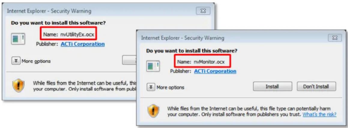
Accept ActiveX Controls Installation Requests
NVR 3.0 system interface requires the add-on ActiveX Control components, please make sure browser's security settings allow ActiveX controls to be downloaded and installed. When your browser asks if you allow ACTi Corporation's add-on components to run, please allow them.
Log in Failure Troubleshooting
Once you confront with problems accessing the NVR server, refer to the possible conditions below and follow the instruction to solve your issues.
Condition 1: Why can't I access NVR server via web browser?
After typing in the correct NVR server IP, if you cannot access NVR Login page, you may get the below browser screens:
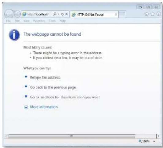
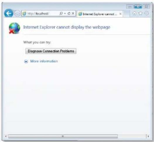
Cause 1: The NVR server is not ready
Solution: It may happen when you just start the NVR server and it is still booting up. Please wait a few seconds and connect again.
Cause 2: The NVR server is not able to respond to your request through current path because port 80 has been seized by another service running on server computer. This may happen when that service is executed right before the NVR server starts its services.
Solution: Please check if there is another service using port 80 right now, and change the setting in that program to release port 80 for the NVR server. Below are the steps to find the service:
- Please click on "Windows Start" (Windows-Logo), then enter "cmd.exe" in the run box and execute it.
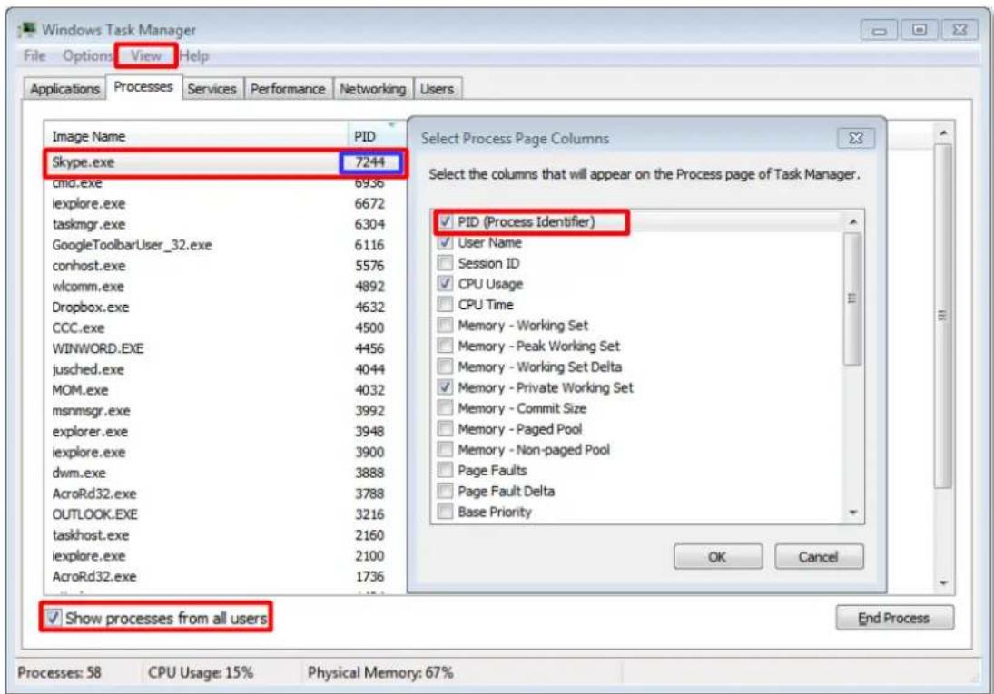
- Input the command "netstat -a -o -b". You will be provided with the ports in use and the services using them. Find the Local Address that has taken port 80, and the PID number.
![C:\Users\Wen.Cheng>netstat -a -o -b Active Connections Proto Local Address Foreign Address State PIN TCP 0.0.0.0:80 Wen-Cheng-HP:0 LISTENING 7244 [Skype.exe] TCP 0.0.0.0:135 Wen-Cheng-HP:0 LISTENING 824 RpcSs [svchost.exe] TCP 0.0.0.0:443 Wen-Cheng-HP:0 LISTENING 7244 [Skype.exe] TCP 0.0.0.0:445 Wen-Cheng-HP:0 LISTENING 4 Can not obtain ownership information TCP 0.0.0.0:3389 Wen-Cheng-HP:0 LISTENING 1344 CryptSvc [svchost.exe] TCP 0.0.0.0:5352 Wen-Cheng-HP:0 LISTENING 4](/content/2026/05/1070493/images/50cf26c7c06b789d873d00b1e8ec04a193c45940fd9d1c3c64c37e2217a28d03.jpg)
- Press down "ctrl"+ "alt" + "Delete" keys to bring up Windows Task Manager. Select "View", then "Select columns", and enable the "PID (Process Identifier)" to appear on search results. Please also make sure "Show process from all users" is enabled.
- On Task Manager Process tab, locate the PID number of the service using port 80. The service name is shown under "Image Name" column.
Condition 2: Why can't I install Active X controls after logging in?
ActiveX Control components are essential for the NVR server to present user interface. The message below will show if these controls were not installed. Please try refreshing the browser first, making IE pop up the prompts again.
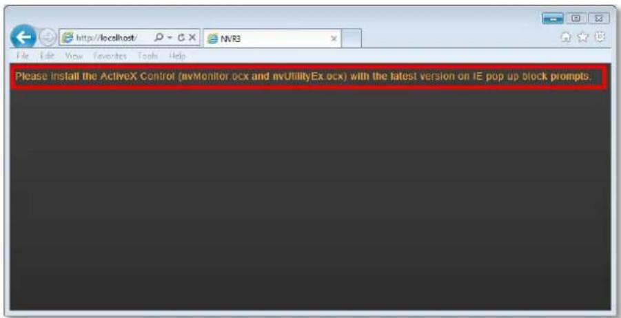
Cause 1: Your Internet Explorer browser version does not support NVR 3.0 system.
Solution: Make sure your browser is 32-bit version.
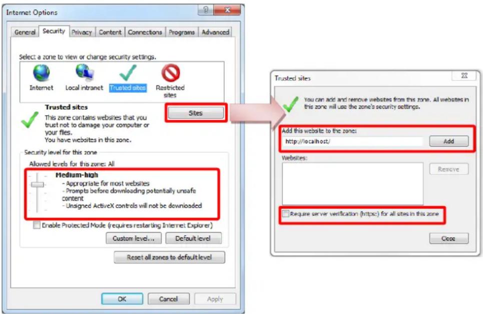
Cause 2: Your browser restricts the installation of add-on components.
Solution: Internet Explorer security settings may restrict the installation of add-on components. To ensure the NVR server is always accessible from your web client regardless of any change in browser's overall Internet security settings, you may add the NVR server site to Internet Explorer's trusted sites. Trusted sites are the sites which you consider safe and wish to visit with low security restrictions while maintaining higher security for the rest of the Internet.
- On IE browser, click Tools → Safety and make sure ActiveX Filtering is unchecked.
- On IE browser, go to Tools → Internet Options → Security tab, select "Trusted sites", set the security level to "Medium High", and then click "Sites".
- Add http://localhost or the NVR server IP to the zone, and clear the box "Require server verification (https:) for all sites in this zone".
- Back on Security tab, click "Apply" to apply the changes. This will allow ActiveX and scripting to be available for the chosen sites but not for the Internet as a whole.
Login
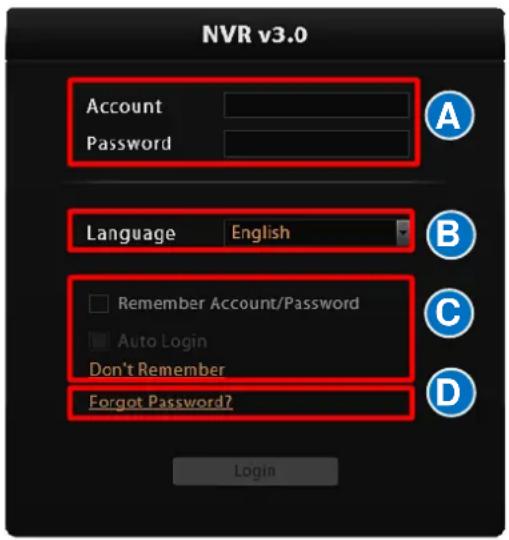
A. Enter Account & Password
Account (non case-sensitive):
Admin (default)
Password (case-sensitive):
123456 (default)
B. Change UI language
To change UI language, select the desired language from "Language" dropdown list.
C. Remember Account/Password
To have the server remember your Login Account and Password in the future, check "Remember Account/Password". Click "Don't Remember" will clear your input text and reset to default.
To directly enter the main page every time you log in, check "Remember Account/Password" then "Auto Login" to skip the Login page. If your computer may be accessed by someone without proper authority, please DO NOT use either of these functions.
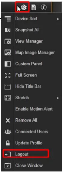
To cancel auto-login, on title bar, click → "Logout" to return to login page, and this function will be disabled.
D. Retrieve the User Password
Please refer to E. Retrieve the User Password on page 48.
Set up the System
This chapter will guide you through everything you need to know in System Setup procedure from first time connection with ACTi NVR 3.0 server to general system configuration.
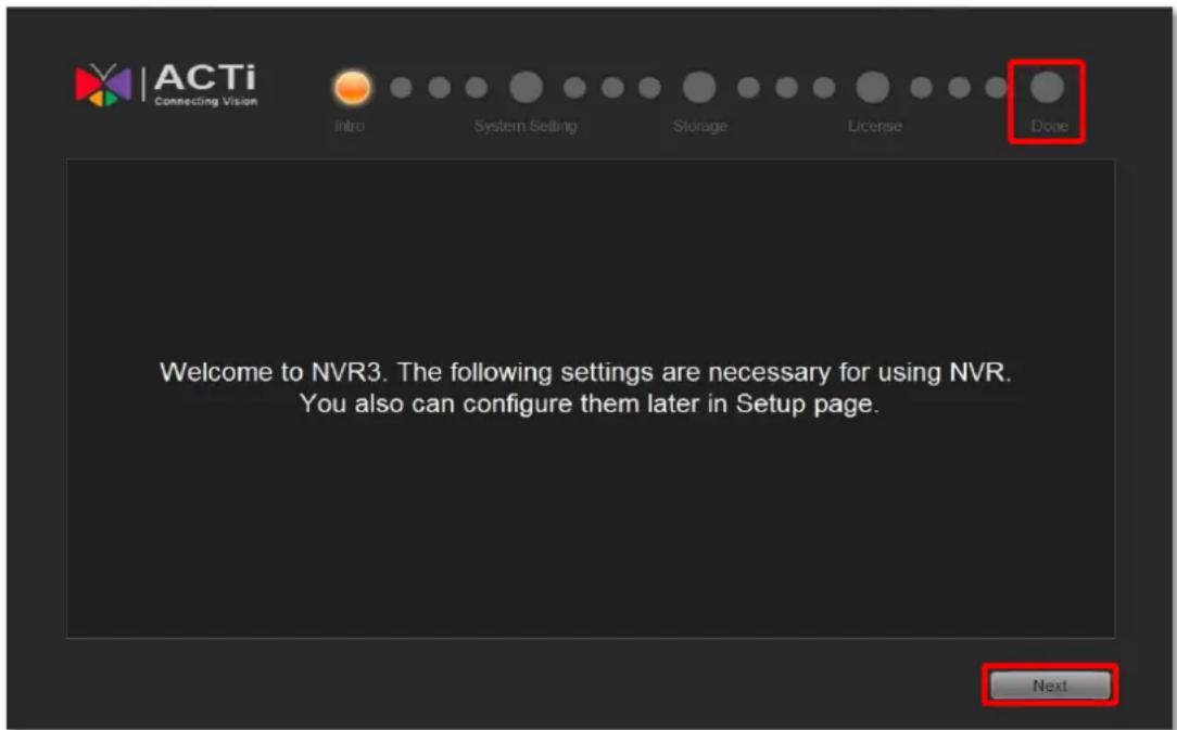
Setup Wizard
Once you connect to ACTi NVR 3.0 for the first time, Setup Wizard will guide you through the initial setup process. You may click "Previous" or "Next" button located on the lower right at any time. This will skip the current step so that you may come back to it later. All the settings in the Setup Wizard are available in the Setup page.
To skip this wizard, click the bubble "Done" on top right corner.
System Settings
You can adjust the E-mail & SMTP settings, FTP settings for event rules now or later. For more details about the settings, please refer to How to Setup SMTP Settings for Event Rules on page 103 and How to Setup FTP Settings for Event Rules on page 104.
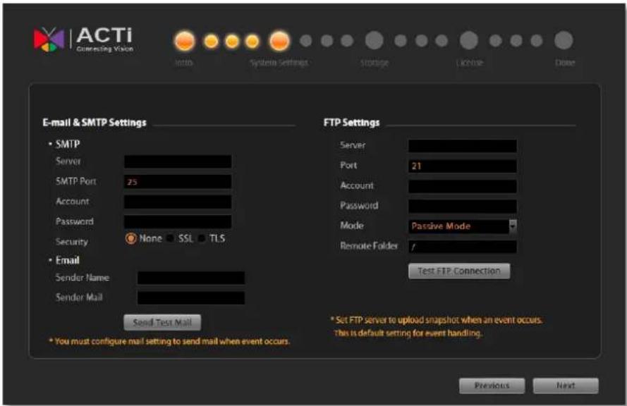
Storage
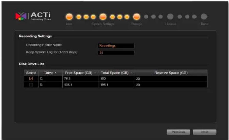
On NVR server, you may choose which disk drives to store the recording files, and decide how much memory space is left for all computer applications to run. You must configure the Drive and Reserve Space for recording. Reserve Space is the space on the drive that will not be used to save recording files, the deletion of earliest recording files will be performed if available space has decreased to reach below Reserve Space configuration; you may choose one or multiple disk drives in Disk Drive List to save the recordings. If you skip this step, Drive C will be the default drive. For more details about the settings, please refer to Storage Management on page 109.
Licensing
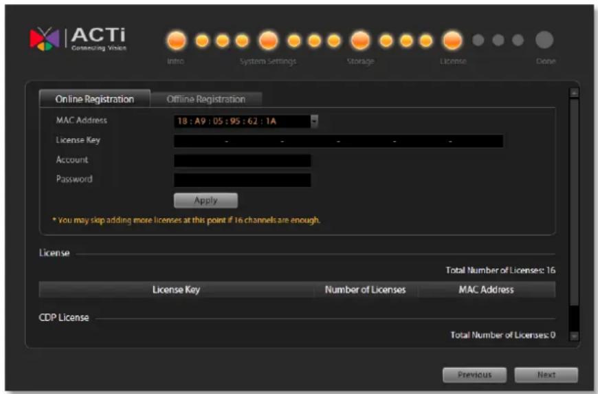
This is the license management section. On lower right part of the screen shows number of channels allowed under your current license. Each NVR server has a license for 16 channels which is already activated. You can click "Next" to next setting if you do not want to add new license for now. For more details about the settings, please refer to License and Activation on page 41.
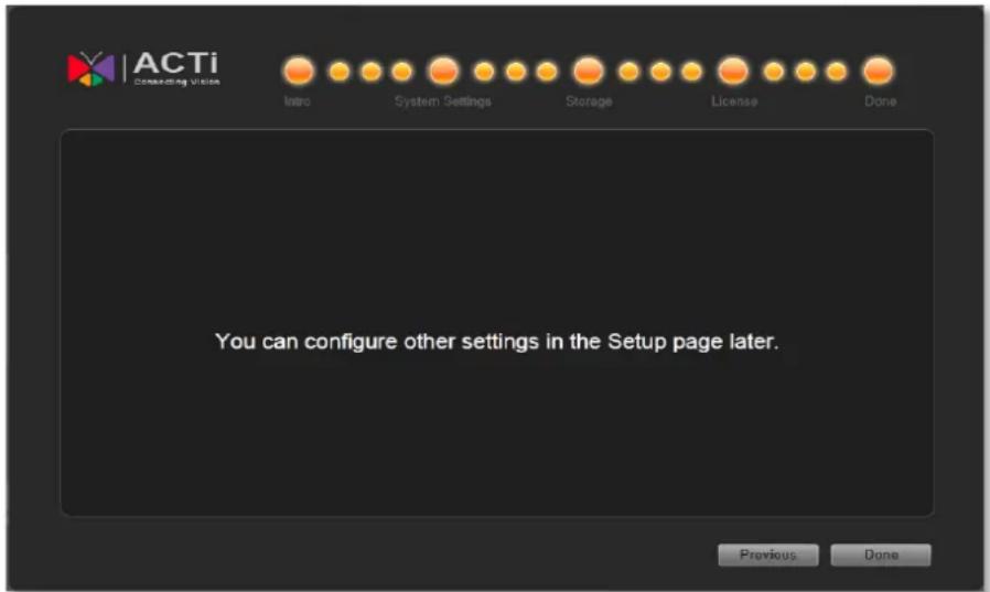
The End of Setup Wizard
Click "Done" to complete Setup Wizard, the previous configuration steps you have gone through are available in Setup page.
NVR Main Screen
You will enter the live view screen after Setup Wizard. On the right are link buttons to three NVR major functions: (1) Live view, (2) Playback and (3) Setup. You can click the orange button to enter the function page.
Live View
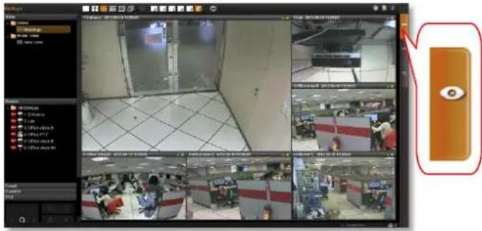
In this module, you can see live view from cameras, perform PTZ operations with mouse or Joystick, view system log, receive alerts on the event panel, setup view layouts, perform manual recording or take a snapshot.
Playback
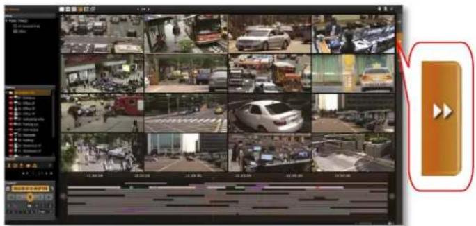
You may search and view playback of multiple channels synchronously. Snapshots or video segments can be taken from playback files. Recorded files can also be exported to AVI format here.
Setup
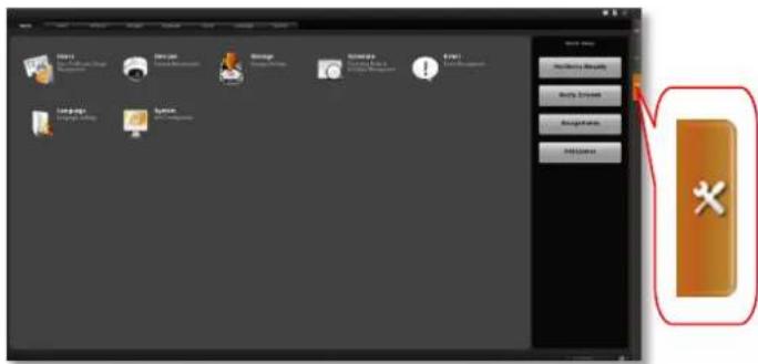
This module includes user setup, device setup, event setup, schedule setup and system-wide settings.
Add Devices
Cameras or video encoders are the fundamental building blocks of surveillance systems. To manage cameras from GNR-3000, you have to add camera devices into NVR3 system first. In this section, we will guide you through how to add or delete devices on the NVR3 system.
To start adding new devices, please follow these steps:
- On Setup page→Home screen, click "Device".
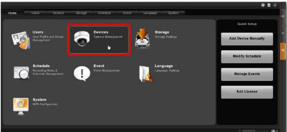
- On Devices page, the Device List is currently empty, and you need to add some video sources to it. Now click "Add Device".
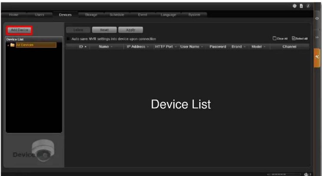
-
There are three ways to add devices into the system, Search Devices, Search ONVIF Devices, and Add Device Manually.
-
Use Search Devices to auto search ACTi cameras located in the same subnet as your NVR server.
- Use Search ONVIF Devices to find devices that support ONVIF in the same subnet as your NVR server.
- If your cameras / video encoders are located outside of a local subnet or over WAN, add
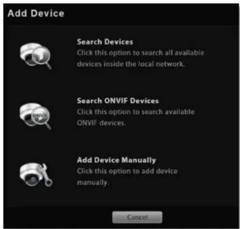
them to your NVR server by using the Add Device Manually button. You will need to know the IP address of the device to add it manually.
Search Devices Within Local Area Network
- Select "Search Devices". Once the search is completed, a list of the devices in your LAN will be shown. Click on the title header to sort by that column. Click on the header again to sort in reverse order. For faster search, you may type a specific IP address or a part of the IP address in IP Filter as a filter and click to narrow down the search result.
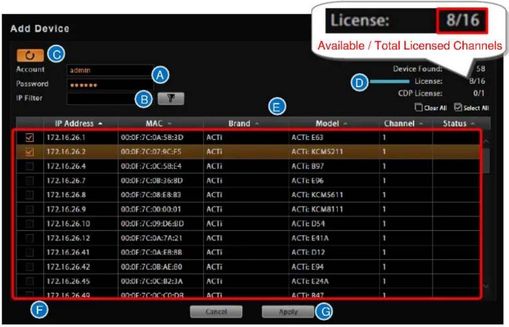
A. Account/Password text box
C. "Refresh" button
E. Column title
G. "Apply" button
B. IP filter (for multiple networks)
D. Available / Total Licensed Channels
F. Search result
- Select the row of the camera you wish to add to the system and repeat this step until you have checked all the devices you need. Please note that the list of devices is shown regardless of the account name and password. You can choose to add all shown devices. For those with different account and password, you will be prompted to fill in the correct credentials to in order access the video feed. To perform the search using different credentials, fill in the new Account and Password and click the "Refresh" button
- Click "Apply" to add selected devices into NVR system.
Search Devices Within Local Area Network with ONVIF
- After selecting "Search ONVIF Devices", fill in the account name and password for the device you want to add.
- Click the "Search" button ☐. Once the search is completed, a list of available devices will be shown. You may click on the title header to sort by that column. Click the header again to sort in the reverse order. For faster search, you may type a specific IP address or a part of the IP address in IP Filter as a filter, and click ☐ to narrow down the search result.
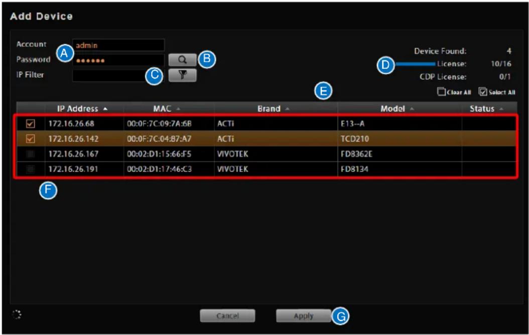
A. Account/Password text box
B. "Search" button
C. IP filter (for multiple networks)
D. Available / Total Licensed Channels
E. Column title
F. Search result
G. "Apply" button
- Select the row of the camera you wish to add to the system and repeat this step until you have checked all the devices you need.
- Click "Apply" to add selected devices into NVR system.
Important Notice
- For certain non-ACTi devices, you may need to configure the ONVIF user credentials of the camera by accessing its Web Configuration page and managing the ONVIF Users List.
- Functions supported for devices added through ONVIF are live streaming and adjustments to video image settings.
Add Devices on WAN or Other Local Area Networks
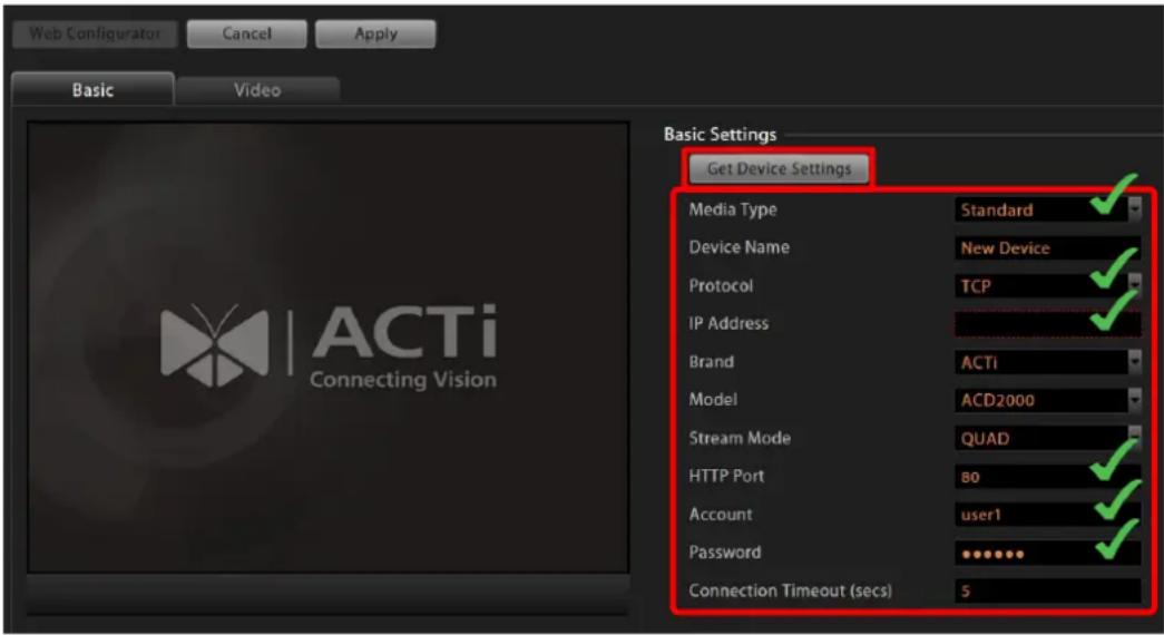
- After selecting "Add Device Manually", the camera settings page will appear as below. The most important settings are (1) Media Type, (2) Protocol, (3) IP Address, (4) HTTP Port, and (5) User Name & Password. Please fill in these required fields for NVR to communicate with the device.
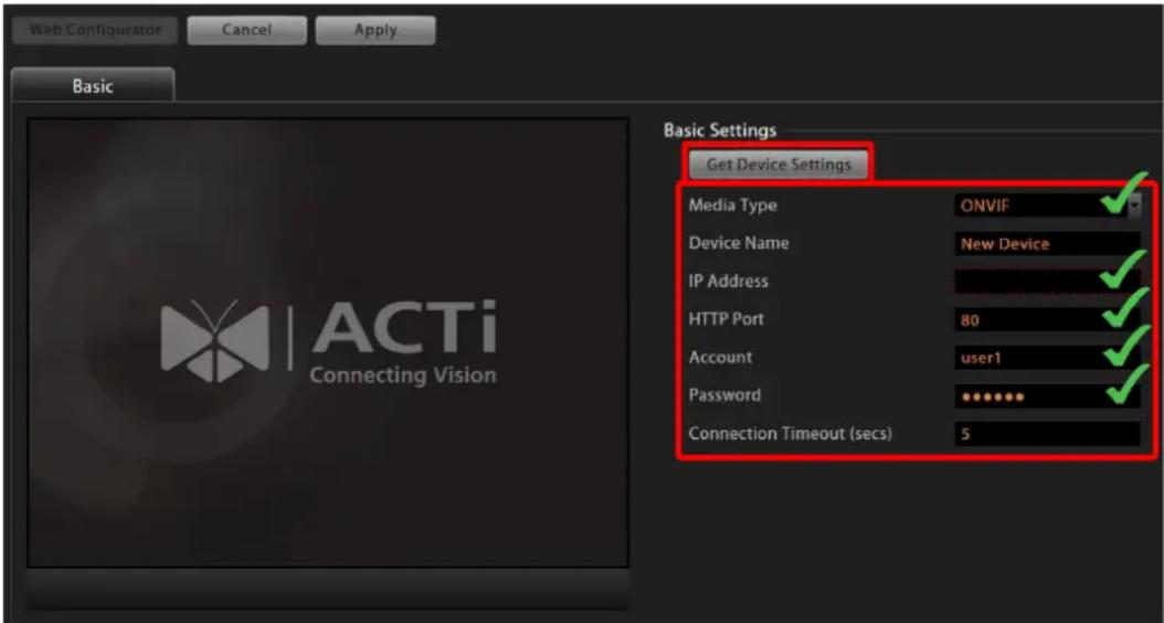
If the device you wish to add supports ONVIF, you can select ONVIF for Media Type, and the settings page will appear as below. The most important settings are (1) Media Type, (2) Camera IP, (3) HTTP Port, and (4) User Name & Password. Please fill in these required fields for NVR to communicate with the device.
Important Notice
If any of the required fields is incorrect, NVR will not be able to connect the device. When you have any device connection problem, please check these settings. However, at this point, you may skip filling in the Device Name, Brand, Model, and Stream Mode configuration.
- Click "Get Device Settings" to have NVR contact the device and get the live view. Once connected to the device, NVR will get all the device properties such like Brand, Model, Device Serial Number, Firmware Version. If the device supports dual stream, Stream Mode selection field will be revealed, and you may select a different streaming mode and configure relative options. You may click "Cancel" button on the top to abort setting this device or "Apply" to save it.
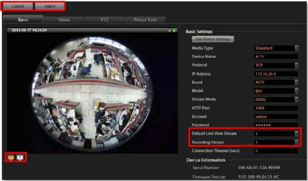
- To directly access the device configurator webpage, simply click "Web Configurator" on the top right to open it. Certain detailed settings can only be accessed through the web configurator and not through NVR.
Basic Settings Attributes
| Field Name | Description |
| Media Type | Select the media type of the camera, choosing either “Standard” or “ONVIF”. To connect with a camera using ONVIF, please make sure the camera device supports ONVIF. |
| Device Name | Enter the name of the camera, which will be shown in the Device list on the left in Live View. This name should be descriptive so that you know where the camera is located. |
| Protocol | Select a streaming protocol to connect the camera with. |
| IP address | Enter the camera's IP address or host name. |
| Brand | Select the manufacturer of device. |
| Model | Select the device model of the IP cameras / video servers. In most cases, this is automatically filled in after you perform Get Device Setting for ACTi cameras. |
| Stream Mode*1 | Select one of the streaming modes this device supports. |
| Channel No. *2 | The channel ID you set for a stream of a multi-streaming device. |
| HTTP Port | Enter the HTTP port for IP cameras/ video servers. Most cameras use the default port number - 80. |
| User Name | Enter the user name to access the camera. |
| Password | Enter the password to access the camera. |
| Default Live View Stream*3 | Choose the streaming id for Live View. |
| Recording Stream*3 | Choose the streaming id for Recording. |
| Connection Timeout(0~99 secs) | Enter length of time allowed for a device to respond to NVR. If the response is to late as to exceed this time, NVR will consider this device “disconnected”. We recommend you to set different values for different types of connection. The default setting is 5 seconds. For devices located over the WAN, you may wish to increase this value to allow for occasional Internet lags. |
*1 Available when NVR is connected to a multi-streaming device.
^*2 Available when NVR is connected to a device that is concurrently in multi-streaming mode (Dual Stream mode excluded).
*3 Available when NVR is connected to a multi-streaming device in Dual Stream mode.
Note
Current NVR version does not support ePTZ operation of 6VGA streaming mode. Please define 6 VGA views through camera web configurator.
Device Status
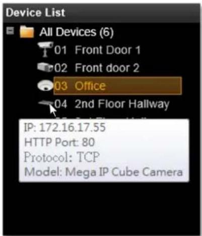
To validate if you have successfully added a device to NVR system, simply check the Device List on the left of Setup
→Devices tab to see if the device name appears in the tree.
Point your mouse cursor over the device icon will bring up an information box containing the device's IP Address, HTTP Port,
Protocol and device type.
Status Icon Description
| Icon | Status Description |
 | NVR server cannot retrieve video streaming. This may be that a video server is not connected with cameras, or that the streaming is blocked by the firewall between the device and NVR server. Please (1) ensure the device side is well connected and can output video normally,(2) check the firewall and port forwarding settings. |
 | This device's settings have been modified but not saved yet. If you leave these modifications unsaved, they will not take effect by next time the server starts. Please always remember to save upon every change. |
 | NVR cannot build up connection with this device. Please check the device connection settings (including IP Address, Port number, Account Name and Password); or increase the “Connection Timeout” to allow more time for th device to respond. |
 | This device is currently connected, video is being transmitted and no recording is proceeding. |
 | This device is currently connected, and video is being recorded either manually or according to the schedule. |
Add Non-ACTi Cameras
In this section, we will guide you through how to add devices to NVR3 system.
After the required CDP license is activated, please:
- Use the utility provided by camera manufacturer to confirm the camera properties:
(1) Protocol, (2) IP Address, (3) HTTP Port, and (4) User Name & Password.
- Log in to NVR, go to Setup page→ "Device" tab, click "Add Device", and select "Add Device Manually".
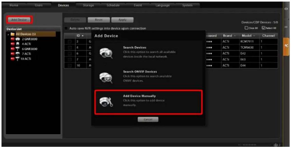
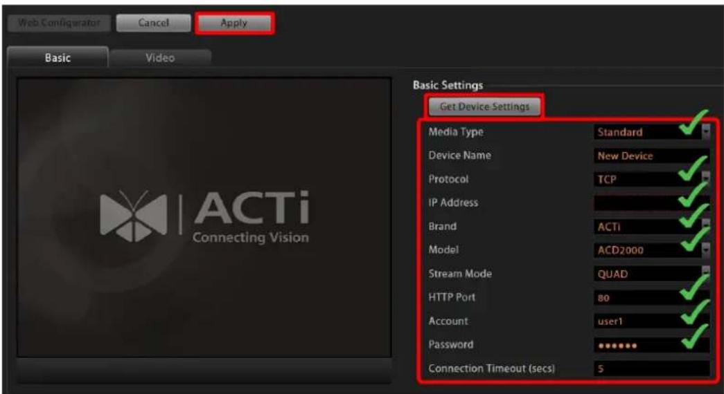
- After selecting "Add Device Manually", the camera settings page will appear as below. Please fill in the eight marked fields shown below that are required to communicate with the device - Media Type, Protocol, IP Address, Brand, Model, HTTP Port, User Name, and Password, and then click "Apply".
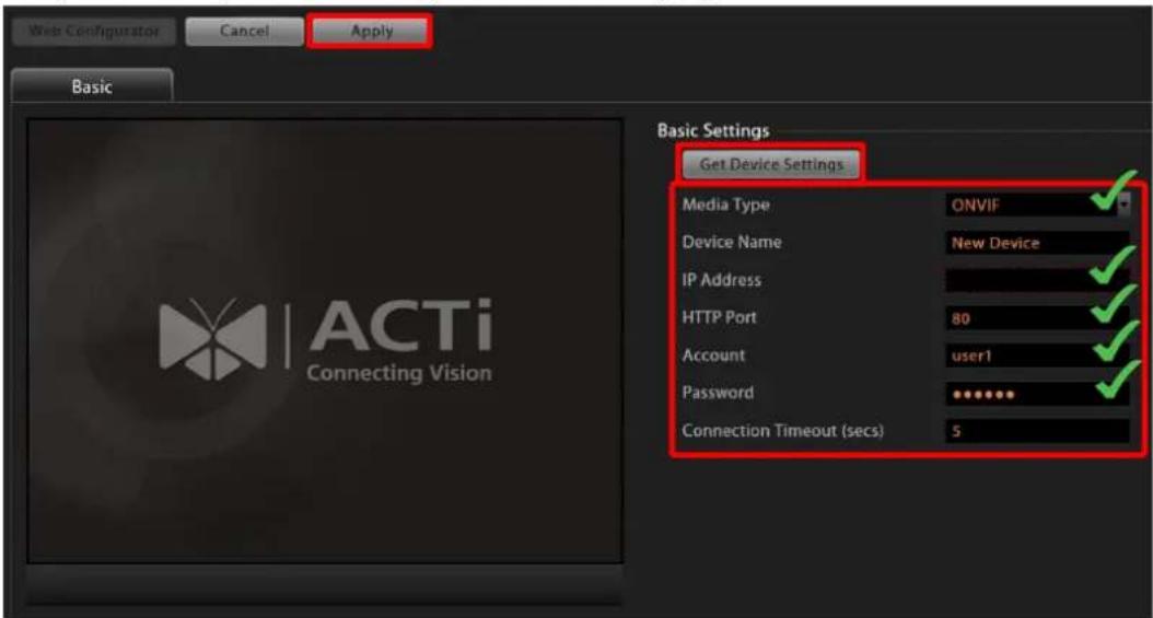
If the device you wish to add supports ONVIF, you can select "ONVIF" for Media Type, and the settings page will appear as below. Please fill in the five marked fields shown below that are required to communicate with the device - Media Type, Camera IP, HTTP Port, User Name, and Password, and then click "Apply".
- By applying the settings, the NVR server will get the video stream, and the camera will have been successfully added to the NVR system. You may click Video, PTZ, or Preset Tour (available for camera with pan/tilt/zoom capabilities) tabs to configure other properties.
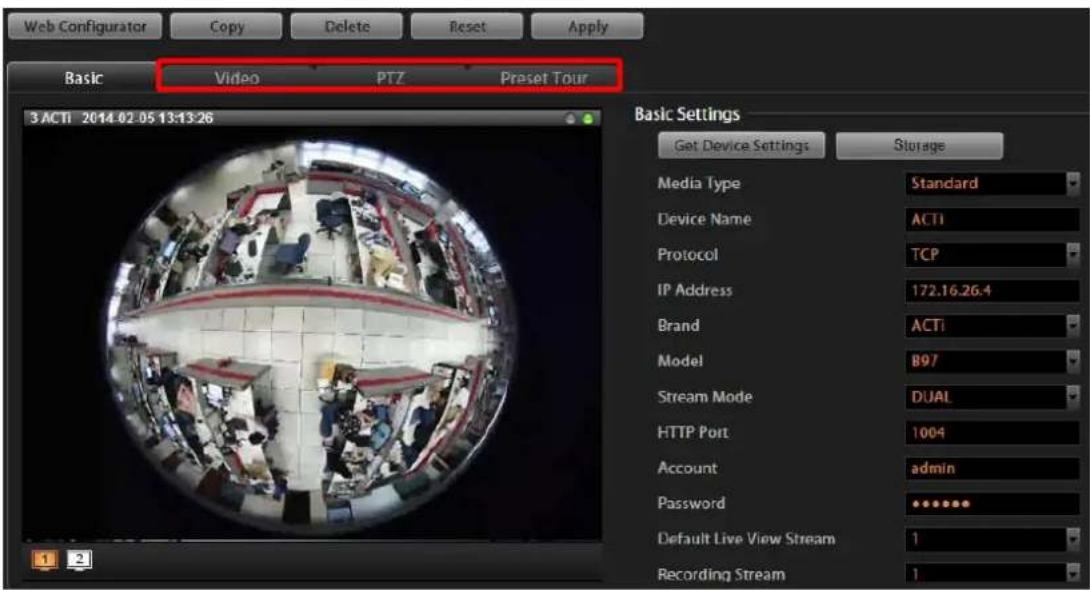
- To directly access the device configurator webpage, simply click "Web Configurator" on top left to open it. Certain advanced settings are only available through the web configurator and not through NVR.
Manage Multiple Devices
After adding several devices to the system, you may get an overview of all devices on Setup page→Device tab; this is where you may use certain fast and convenient approaches to manage a number of devices. In this section, we will guide you through how to quickly add or delete multiple devices.
Modify Basic Connection Settings
Go to Setup page → Devices tab, and click All Devices in Device List to get the devices overview in right column. Each basic connection setting field including Name, IP Address, HTTP Port, User Name and Password, is editable. Simply click in the field to modify it directly.

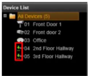
Every time you modify a property without saving it, an icon
will appear
next to the device in Device List. You may click "Reset" to retrieve the settings you saved last time once you want to abort current modificaiton.
After changing any field, please remember to click "Apply" before you leave this page.
Tip
NVR will sync with devices upon connecting to them. To make sure the settings on NVR side are prior to and always overwrite those on device sides, please check "Auto save NVR settings into devices upon connection".
Delete Devices
You may delete a single, multiple or all devices on All Devices List. The logs and video files of the devices will be kept until deleted by server storage deletion rule. Select the device(s) you wish to delete, click "Delete" button and confirm the deletion. If you want to delete all the existing devices, simply click ☑ Select All on upper right to select them
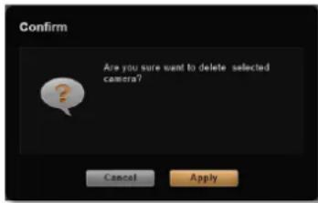
all at once. To validate if you have successfully deleted a device on NVR system, simply check the Device List on the left of Setup page → Devices tab to see if the device name is removed from the tree.
Copy Settings Across Devices
When setting a large number of devices, many settings will resemble other ones, and it is sometimes tiresome to repeat every setting again and again. You can use the Copy function to save the hassle of needless repetition.
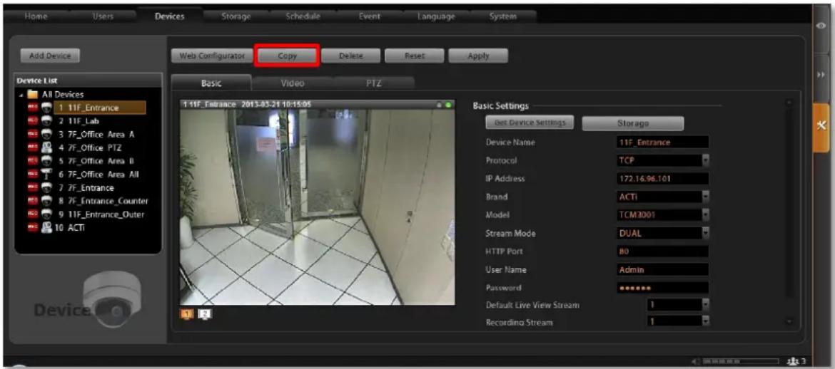
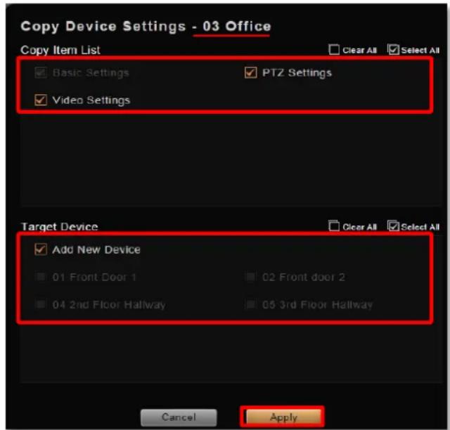
- On All Device List, select the source device whose settings are to be copied from. You can select only one device to be the source.
- Click "Copy" to bring up the copy setting window.
- On the window, below the source device name are the settings you may choose to copy, including Basic settings, PTZ Settings and Video Settings.
- Click "Apply", the settings will be written to target devices.
- To add a new device with the same settings, choose "Add New Device" in
Target Device area, and then click "Apply" to go to a new device page. Each field on this page has already been filled with the source device's properties. You may continue to modify the Device Name, IP Address, get the live view by clicking "Get Device Settings", and then click "Apply" to add this device to Device List.
- There are a few differences of the copied items between two target device types:
Settings Copied to Target Devices
| Settings\Target Type | New Device | Existing Device |
| Basic | All | All except Device Name, IP Address, HTTP Port, RTSP Port, User Name and Password |
| Video | All except Motion Settings, Video Adjustment | |
| PTZ | All except PTZ Preset Points and Commands | |
Note
- You can only choose either "Add New Device" or existing devices as target.
- To add new devices by copying from an existing one, the user's group should be permitted with this right. To check the access rights, please go to Setup page→Users page→User Groups, select the user group, and enable the "Device Setup" - "Add New Device" under NVR Permissions.
Add Video Streams from a Multi-channel Device
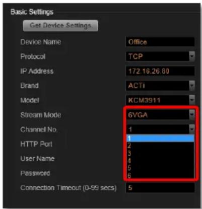
There are devices that output more than one video streams to NVR. For example, a video encoder converts a number of analog video signals into the same amount of IP video streams; certain high megapixel cameras such as ACTi KCM-5111, supports outputting multiple VGA streams cropped from a single high-resolution video source. These multiple streams coming from a single device are managed as different cameras by NVR server.
To add these streams as multiple channels for you to view and record, please:
- Select the desired stream mode in "Stream Mode" field on Setup page → Devices tab → Basic tab.
- The "Channel No." column will display for you to input the stream ID (the same with your setting in device's web configurator).
- After configuration, click "Apply".
- Go to All Devices page, duplicate this device to a new channel, repeat this step until all the channels you need are added.
- Individually modify the Channel No value of the channels.
Tip
Saving CPU loading with Your Dual Streaming devices
The device supporting dual-streaming function can output two video streams of different value. You may make the live view stream smaller in size with lesser frame rate to save decoding CPU power and bandwidth. Meanwhile the recording stream can be larger and have more FPS so that you have clear images when you need to retrieve evidence. For settings in both streams of devices with dual stream functionality, please refer to section Configure Video Format on page 72
Configure Device Settings
After adding a device to NVR, you may continue to configure its video, motion detection, PTZ or preset tour settings on Setup page→Devices tab. In this section, we will guide you through how to configure these settings and their corresponding functions.
Configure Video Format
Go to Setup page →Device tab, select a device from Device List, and then go to Video tab to configure the video format of the stream output from this device. If the device is currently in Dual Stream mode, you may switch the stream in live view window by click on the switch below 12 and configure individual settings for Media 1 and Media 2.
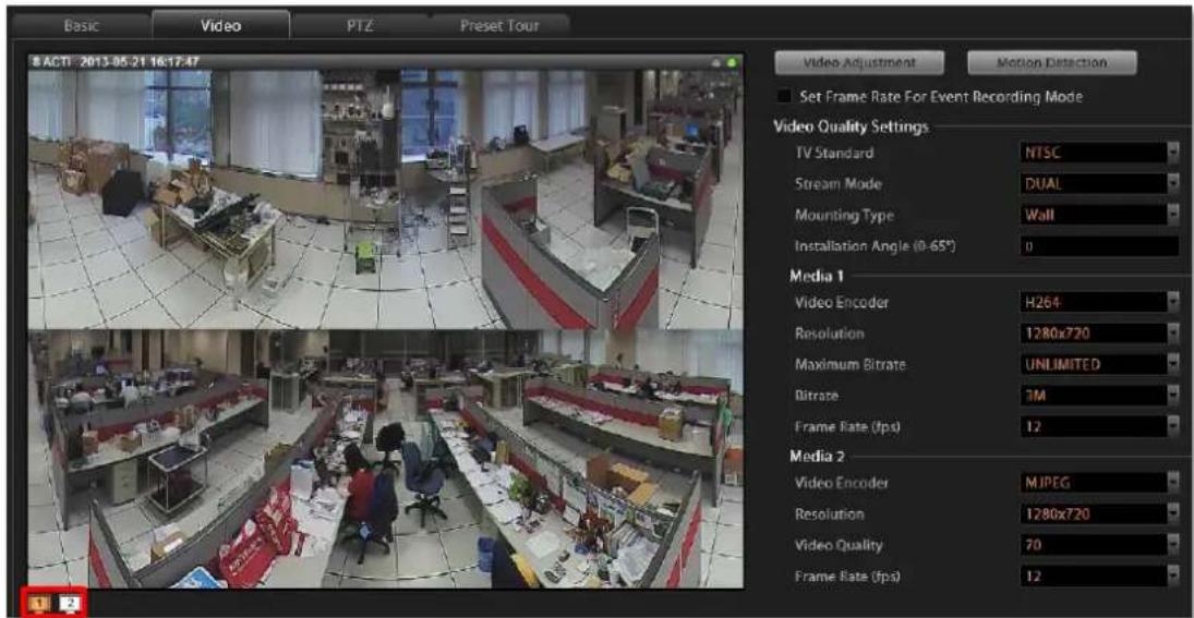
Video Settings Attributes
| Field Name | Description |
| TV Standard | Default is NTSC |
| Stream Mode*1 | Select one of the streaming modes this device supports |
| Mounting Type*2 | Select the mounting position |
| Installation Angle*3 | Input the angle for a device mounted on the wall |
| Video encoder | Select one of the codec this device supports |
| Resolution | Select one of the resolutions this device supports |
| Video Quality*4 | Select your desired video quality of the image |
| Frame Rate(fps) | Select the (Frames Per Second) this device supports. |
| Maximum Bitrate | This puts a hard cap on the maximum bit rate allowed in any given second of streaming. Assigning a limited bit rate may cause a few dropped frames when the stream data overflows the allowed bit rate. |
| Bitrate*5 | This is the target bitrate that the camera will attempt to provide when you have selected “Unlimited” for Maximum Bitrate. The actual value will fluctuate slightly based on scene changes. |
*1 Available when NVR is connected to a multi-streaming device.
^*2 Available when NVR is connected to a hemispheric device.
*3 Available for hemispheric devices with "Wall" Mount Type.
*4 Available when "Video Encoder" is selected as MJPEG.
*5 Available when "Maximum Bitrate" is selected as "Unlimited".
Save Storage by Setting Event Recording Frame Rate
Video surveillance system is aimed to preserve as much evidence as possible, and you may want to have a view be recorded 24/7 to capture every important moment; however, the general recording methods provided by most network recording systems- event and schedule recording, will either consume too much storage or have risk in missing important scenes. The "Set Frame Rate for Event Recording Mode" function record everything at economical storage usage by automatically adjusting video frame rate during event recording period.
Schedule Recording
Continuous recording promises no loss of video evidence; however, large data storage is required because this video is always recorded at the high frame rate you set for device.
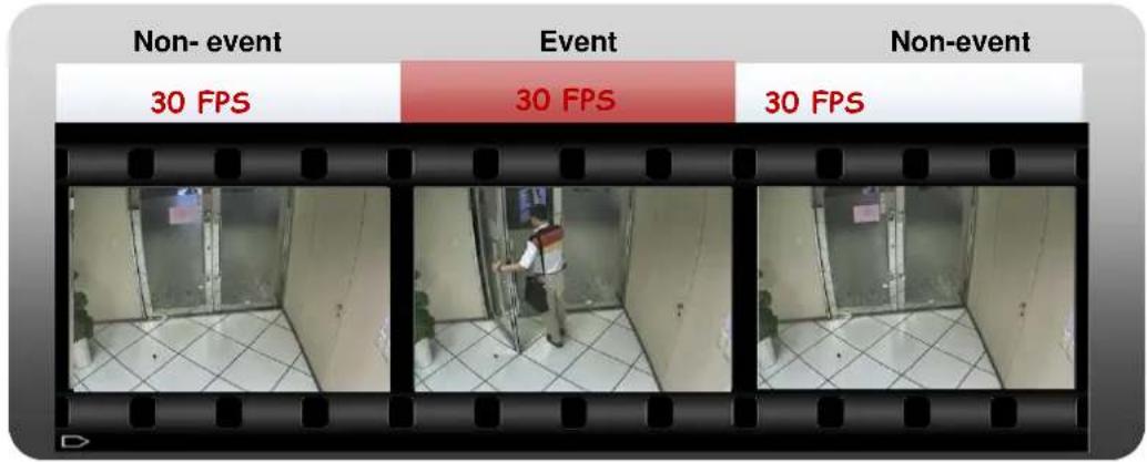
Event Recording
This mode is storage-efficient because recording would stop during the non-event moments; while certain vital video evidences may be missed if the triggering device fails to take effect.
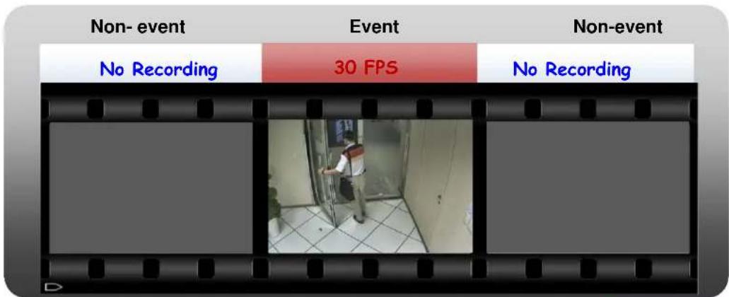
Event Recording with Frame Rate Adjustment
Keeps recording all the way without losing any single moment; lower frame rate can be set for non-event recording, which consumes only a little storage.
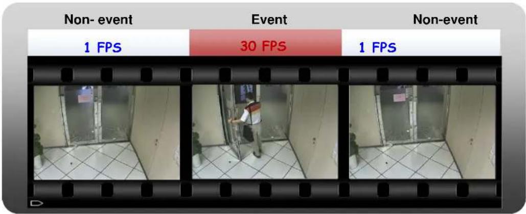
How to Make Use of Event Recording with Frame Rate Adjustment
To make use of Event recording with Frame Rate Adjustment function, you may configure the Frame Rate settings on Setup page →Device tab→Video tab. The Frame Rate (fps) you set will always be applied to live view and schedule recording. Once Set Frame Rate for Event Recording Mode is checked, you may configure advanced settings for event recording. If the device is in Dual stream mode, you will only need to configure these settings of the
Recording Stream.
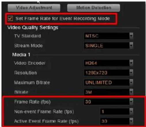
Scenario A:
Suppose you want all the videos recorded at very high frame rate. With sufficient storage, you may not need this function. Set the video Frame Rate that will apply to all the recordings. In this way, NVR 3.0 will not record non-event during event recording period.
| Frame Rate Setting Set Frame Rate for Event Recording Mode | Event Recording |
| Frame Rate (fps)30 | Non-Event: 0 FPS |
| Event: 30 FPS |
Scenario B:
Suppose you wish the system to record 24/7, the non-event recording to be kept at very low frame rate. Please set the event and schedule recordings at different frame rate, you will need to enable "Set Frame Rate for Event Recording Mode", and set the "Non-event Frame Rate" and "Active Event Frame Rate".
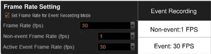
Fine-tune the Image
When monitoring your cameras, it is essential to make the images as similar to the real scene as possible. The default settings of the camera are usually sufficient for most environments, but you may also make adjustments in case it is required to do so. For devices that support the configuration of properties related to image, day/night mode, or exposure/white balance settings, you may directly modify them and save your changes to the device using the NVR 3.0 system. The options available may vary depending on the device.
To start, on Device Video tab, click "Video Adjustment". Each field is only available when the device opens this property for modification. If the device is in Dual Mode, the video you get in this window will always be Stream 1.
- At first, synchronize with the device to get the current settings by clicking "Get Video Adjustment".
- After retrieving the settings from device, the fields available for modification (depends on models) will be enabled. Select the desired value for the field.
- Click "Apply".
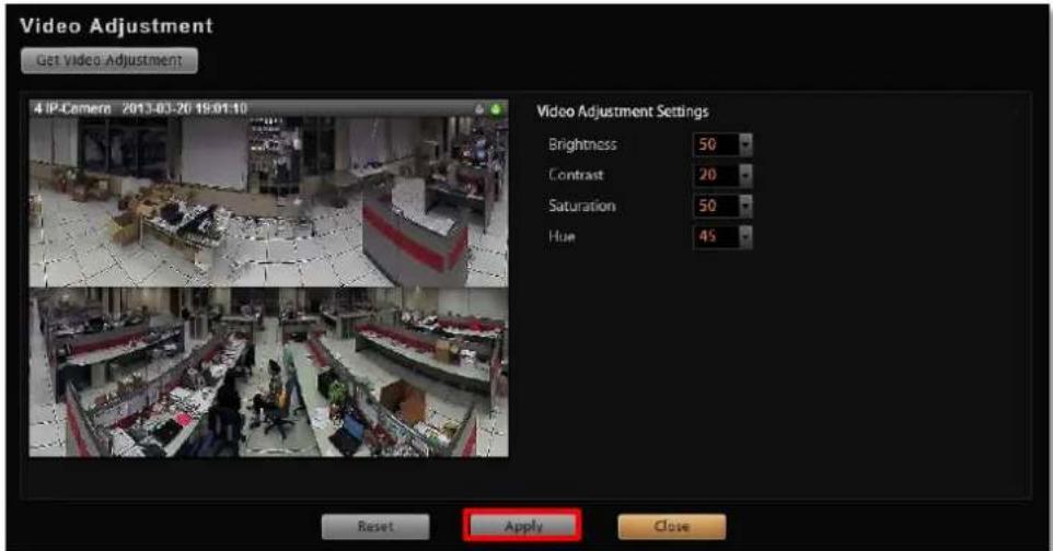
Video Adjustment Attributes
| Field Category | Field Name | Description |
| Image | Video Flipping/Video Mirroring | Check this box to flip the video vertically and horizontally to achieve a 180-degree rotation effect. |
| Brightness | Select the Brightness value (0-100). The higher the value, the brighter the image. | |
| Contrast | Select the Contrast value (0-100). The higher the value, the more obvious the separation between light and dark. | |
| Saturation | Select the Saturation value (0-100). The higher the value, the more intense the color will appear; the lower the value, the more grayed-out the color will appear. | |
| Hue | Select the Hue value (0-100). “Hue” is the term used to refer to the pure spectrum colors. Adjust this value to find the color closest to the real scene. | |
| Digital Noise Reduction | Turn the Digital Noise Reduction ON or OFF. When turned on, the noise in the video (especially in low light) is reduced and the image will look smoother and clearer. | |
| Wide Dynamic Range | Select the WDR level from the following options: Disabled, low, medium, high, highest.Note: WDR is disabled and will not appear if Exposure Mode is set to “Manual”. | |
| Day/Night | Day/Night Mode | Select one of three modes:Auto: The camera will automatically switch between day mode (color) and night mode (black/white) under exposure level defined by “Threshold”.Day: The camera will always stay in the day (color) mode, regardless of exposure level.Night: The camera will always stay in night (black/white) mode regardless of exposure level. |
| Threshold | The scale from 0-100 allows you to define the exposure level at which the day and night mode switch will happen. A higher value would require a darker environment to trigger a day to night switch and vice versa. | |
| Exposure/White Balance | Exposure Mode | Select between “Auto” or “Manual” exposure mode. In Auto mode, the intelligent system of the camera will find the best possible exposure settings. In Manual mode, you can manually adjust the White Balance, Exposure Gain, Shutter Speed, and Line frequency. |
| White Balance | Select between “Auto” or “Manual” White Balance | |
| Exposure/White Balance | mode. White balance refers to the device's ability to accurately define “true white” color. In Auto mode, the camera will attempt to recognize the “true white” color and adjust the image accordingly. In Manual mode, you can configure the White Balance by adjusting the R Gain and B Gain value manually. | |
| R Gain | The scale from 1-255 allows you to define the R Gain level of the video frame. A higher value would adjust the image to have more red color value. | |
| B Gain | The scale from 1-255 allows you to define the B Gain level of the video frame. A higher value would adjust the image to have more blue color value. | |
| AE Reference Target | The scale from 1-255 allows you to define the Auto exposure reference target. A higher value will brighten the overall scene, although it may increase the amount of noise at night. | |
| Exposure Gain | The scale from 1-255 allows you to define the Exposure Gain level of the video frame. A higher value would make the video frame brighter. | |
| Shutter Speed | Shutter speed allows you to choose the speed of auto shutter. | |
| IRIS Control | IRIS control allows you to configure the size for the opening of the iris | |
| Line Frequency | Select between 50Hz or 60Hz to match with the frequency of artificial light source of a given country. |
Configure Motion Settings
To make use of the motion and PIR detection functions supported by your devices, you need to configure the detection regions and settings. Once a motion is detected, NVR 3.0 can trigger events and recording, bring up instant pop-up windows and show the detected area on live view.
Before configuring motion detection settings, first make sure you can connect properly to the IP camera / video server and get device settings. On Device tab→Video tab, and click "Motion Detection" to start.
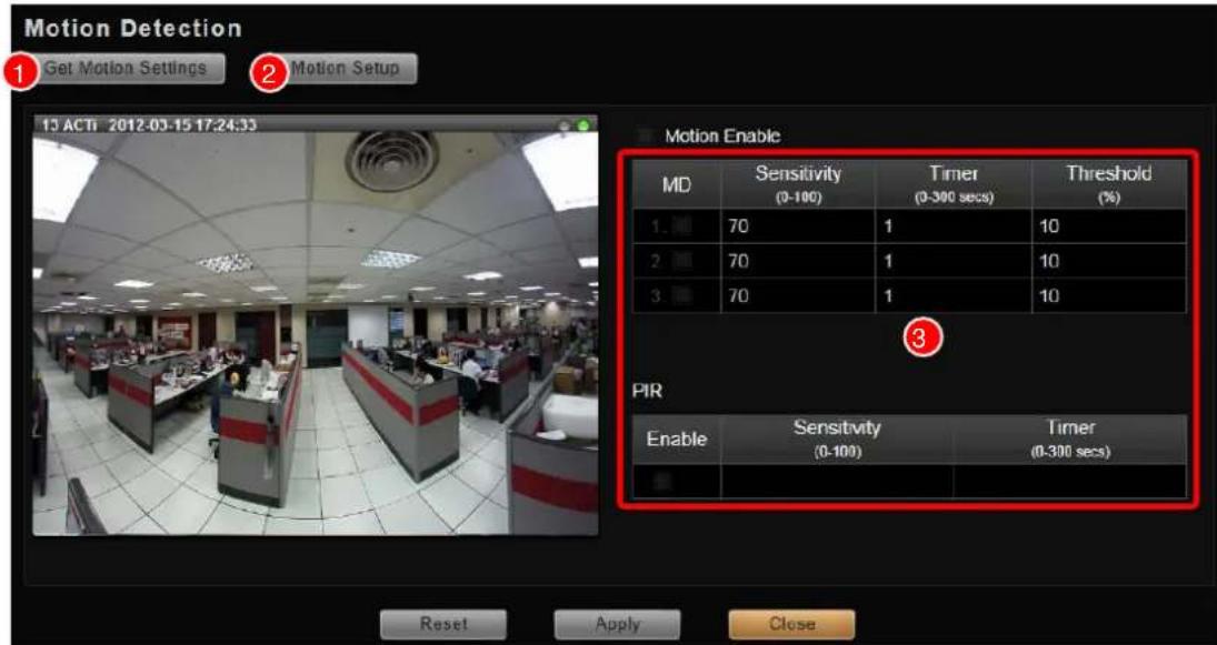
- Click "Get Motion Settings" to retrieve the live view. For Dual Mode, the video you get in this window will always be Stream 1
- Click "Motion Setup" to enable the property fields.
- There are three motion regions for you to set. To enable one, check it in the MD box, a red frame will appear in the view. You may start setting the detection area by adjusting this red frame on the view. Simply use your mouse to move and resize the frame.
To move the entire frame
Place the mouse cursor over the title bar, and drag to move.
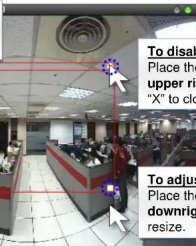
To disable this detection region
Place the mouse cursor over the upper right corner, and click the "X" to close this frame.
To adjust the region dimension
Place the mouse cursor over the downright corner, and drag to resize.
- When the setting is finished, click "Apply" to save, then "Close" to exit this page. To check or modify the regions you set, please go through clicking "Get Motion Settings", Motion Setup" and then "Motion Enable" buttons, the saved regions are already selected on the list, select one to proceed.
Adjustment Attributes
| Field Name | Description |
| Sensitivity(1-100) | Determines how sensitive the camera reacts to the movement. The higher the sensitivity level is, the smaller motion will trigger the alarm, but may give false alarms. Default is 70. |
| Timer(0-300 secs) | The interval before the next motion detection can be triggered again. Default is 1 second. |
| Threshold (%) | The threshold level of this motion detection region. The lower threshold level is, smaller portion of the region would be considered as motions, which is more easily to be triggered, but may give more false alarms. |
Note
- If you have changed the motion detection settings via the web configurator, please remember to come back to NVR and press "Get Device Settings", then "Apply" to save to NVR. This is to ensure that the settings in NVR are always in sync with the device.
- If a motion region is set, once a movement is detected in this region, in live view: (1) the red region frame will blink, and (2) a new alert entry will be generated in the event list.
- PIR detection is available only for models with this function.
Configure Storage Card Settings
Certain camera models come with the internal storage feature. Via NVR interface, you can observe the storage card's memory status, and configure related settings.
- Make sure the SD card is installed properly in the camera.
- On Setup page → Device tab, select the device form Device List. Click "Storage".
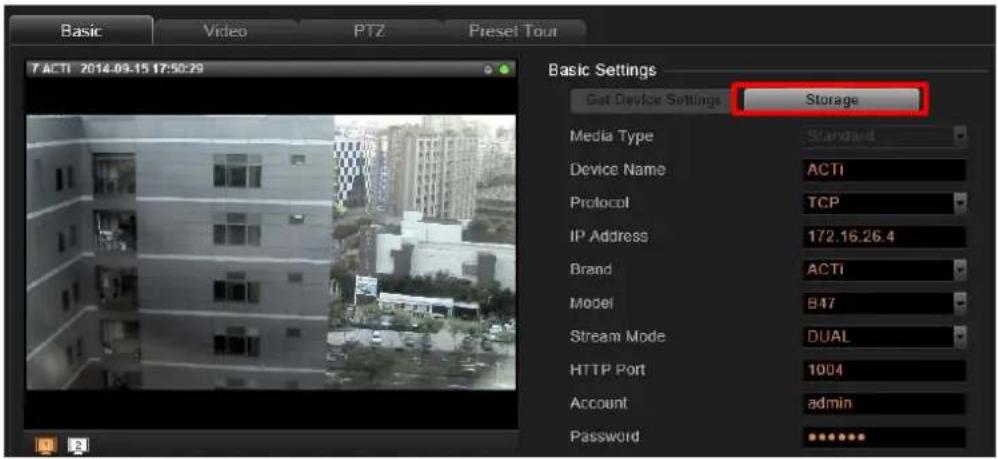
- On Storage window, click "Get Storage Setting" to sync with the SD card.
You can enable "Redundant Recording when Disconnected" function to have this SD card take over the recording service for this channel when this device is disconnected with NVR server. The video recorded on SD card during the disconnection period will automatically be restored back to NVR server upon the recovery of the connection. Click "Apply" to save the setting.
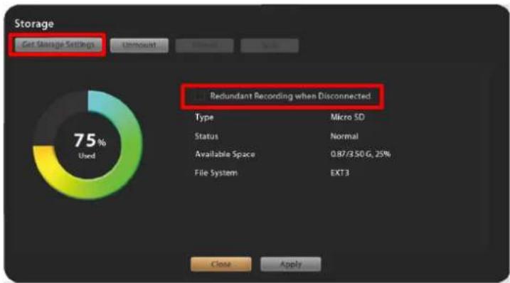
Note
Before you enable "Redundant Recording when Disconnected" function, please do the following (1) upgrade the camera firmware to 6.07 or later version, and then (2) format the SD card either on camera firmware interface or on NVR interface.
Configure PTZ Device
PTZ devices can do panning, tilting and zooming automatically or through manipulation. The PTZ-related applications are broadly supported by NVR 3.0. For example, you may control the movements of a PTZ camera with user interface panel controls or a joystick; the device can be programmed to execute a continuous tour or triggered by events to go to a preset position.
Once an ACTi PTZ device is added to the system, NVR 3.0 will use the default settings of the device model and enable PTZ functions, so that you may immediately start PTZ operations.
If you have previously changed the communication parameters of PTZ devices, please make sure these parameters on NVR side and device side match.
Below is a list of functions supported ACTi solutions and the required settings. When you configure PTZ Protocol properties for ACTi Pan/Tilt/Zoom devices, please make sure the required settings are correct
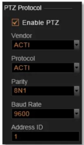
| ACTi Pan/Tilt/Zoom devices | Vendor | Protocol | Baud rate | Parity | Address ID |
| IP Zoom Camera/ IP PTZ Camera | V | V | V | ||
| IP Speed Dome / IP Camera mounted on Scanner/ Analog PTZ camera attached to Video Server | V | V | V | V | V |
To start matching up the parameters, please follow the below procedures:
- If the device is a speed dome camera or an analog camera attached to video server, configure the parameters on physical device according to the product's installation instructions.
- On the device's (camera or video server)web configurator, configure the parameters to match the setting on physical device, and test the PTZ operations to make sure the device is properly set to be connected
- In NVR 3.0 server, go to Setup page → Devices tab, select the device from Device List, and click PTZ tab. In PTZ Protocol section, fill in the communication parameters.
Adjustment Attributes
| Field Name | Description | |||
| Vendor | Vendor is the provider of Protocol. The selectable vendors would vary depending on different device models. Available vendor types are: ACTI, DYNACOLOR, PELCO and SONY. | |||
| Protocol | Protocol is a set of rules to define the communication format between the device and controller. Different protocols are provided for selection according to the Vendor you choose.Available protocols following their vendors are: ACTI: [ACTI] / DYNACOLOR: [DYNACOLOR] / PELCO: [PELCOD] [PELCOP] SONY: [VISCA] | |||
| Parity | Parity is the data validation mechanism for analog devices that use serial port interface to send or receive data. When choosing parity mode other than "none", the data packets will be validated for possible data losses so that failed command could be re-sent if necessary. Please refer to the parity setting of the analog device and choose exactly the same parity setting also in NVR. When setting up ACTi Zoom, PTZ or Speed Dome cameras using “ACTi” protocol, you may ignore the parity setting.Available parity modes are: | |||
| Parity mode name in NVR | Serial data, represented by given amount of bits | Parity mode (none, odd, even) | Number of stop bits | |
| 8N1 | 8 | N | 1 | |
| 8O1 | 8 | O | 1 | |
| 8E1 | 8 | E | 1 | |
| 8N2 | 8 | N | 2 | |
| 8O2 | 8 | O | 2 | |
| 8E2 | 8 | E | 2 | |
| 7N2 | 7 | N | 2 | |
| 7O2 | 7 | O | 2 | |
| 7E2 | 7 | E | 2 | |
| Baud rate | Baud rate defines the data speed through serial port interface – the rate value represents the number of symbols that can be transmitted within 1 second. Please refer to the baud rate setting of the analog device and choose exactly the same baud rate setting also in NVR. When setting up ACTi Zoom, PTZ or Speed Dome cameras using “ACTi” protocol, you may ignore the baud rate setting.Available baud rates:2400, 4800, 9600, 19200, 38400, 57600, 115200 | |||
| Address ID | Address ID represents the identity of the device, only analog devices or speed dome cameras require this configuration. Please refer to the Address ID of the device and choose exactly the same baud rate setting also in NVR 3.0. Available value is from 1~99. By default, ACTi devices will use “1” as Address ID, it is suggested not to change it. | |||
Important Notice
Note that the functions supported for devices connected using ONVIF are live streaming and adjustments to video image settings.
How to Do Live PTZ Operation
To configure PTZ settings, you need to view the live streaming while manipulating the PTZ controls simultaneously in this window.
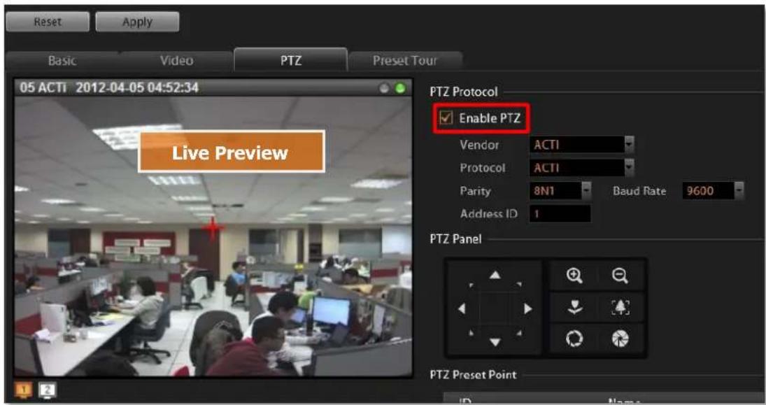
There are two kinds of PTZ navigation:
Optical PTZ Navigation
- Get the live view from Live Preview window:
Make sure the "Enable PTZ" is checked, a red crosshair will appear on the Live Preview window, if the device is in Dual Stream mode, this window will always shows the stream set for live view. You may click on 📄 to switch between the streams.
- Use the mouse to do the following PTZ operations:
To execute optical Panning and Tilting, click anywhere on the live window to allow the camera to move in that direction. The length of the direction indicator is proportional to the Pan and Tilt speed. The farther you place the cursor from the center, the faster the Pan/Tilt movement.
To execute optical Zoom in or Zoom out, scroll the mouse wheel forward to zoom in; scroll the mouse wheel backward to zoom out.
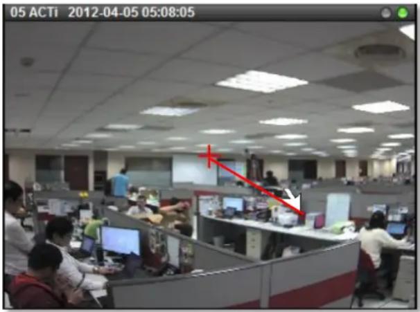
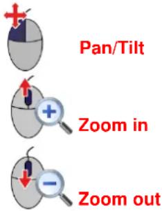
- Use panel controls to operate PTZ movements:
Click a button on the panel to start, the red crosshair will appear in the view.

Note
- The zoom buttons are only applicable for those devices supporting optical zooming.
- The focus buttons are only applicable for devices with controllable zoom lens, e.g. KCM5211. Please remember to turn off the autofocus mode on device firmware before using these buttons.
- The device should be equipped with DC-Iris or P-iris and has been switched to manual iris mode before you use the buttons for widening or narrowing aperture.
Digital PTZ Navigation
Digital PTZ allows you to zoom into part of the video and enlarge it to display on screen. This PTZ function is applied to every camera model in NVR 3.0 system.
- Get the live view from Live Preview window:
Make sure the "Enable PTZ" is unchecked. - Click and drag a highlight rectangle over any channel, and the area highlighted will be displayed in the full live video window. In this mode, a picture-in-picture view will show in the lower right of live view window. A red rectangle will mark the currently enlarged view area within the full size video. You may click and drag the red rectangle to see another area.
- To go back to the original full video view, just right-click on the minimized Picture in Picture view.
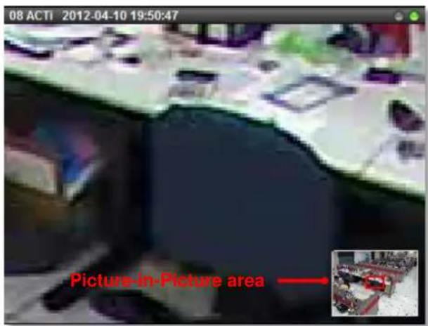

Draw Zoom area

Cancel Zoom area
Set PTZ Preset Points
With PTZ devices, you may define a view by where to look (through panning and tilting) and how close (through zooming) to zoom. Once these views have been saved in NVR server as preset points, the device can always point to this view upon the event triggering or user's command.
- Go to Setup page → Devices tab, select the device from Device List, and click PTZ tab.
- By PTZ operation, control the device to point at your desired view, and adjust the zoom level (if available). In PTZ Preset Point section, click a preset point name field to start editing the name, then click "+" to set this point. After finishing setting your desired preset points, click "Apply". You may review the points you set by clicking "→" to go to the point, or "X" to delete it. You may modify an existing point with following procedure: 1. Select it 2. Define a new view 3. Click the "+" to set it 4. Click "Apply" to save it.
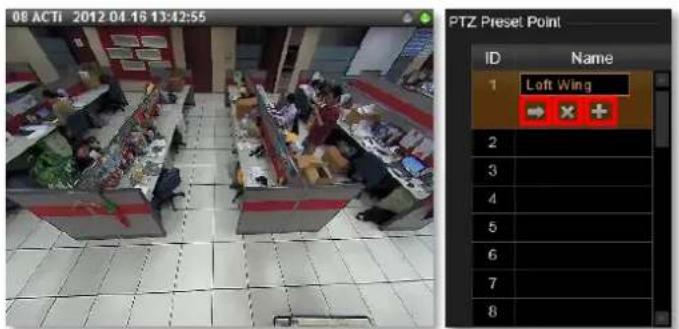
- After the preset points are set, they are available on Live View page →PTZ control panel.
Set PTZ Command
If your speed dome or PTZ device has a special function not supported in the standard protocol, you may input it in PTZ Command list and execute it. Ex: Activate the wiper to clean the window of the PTZ.
-
To add a PTZ action command, go to Setup page → Devices tab, select the device from Device List, on PTZ tab, check the "Enable PTZ".
-
In "PTZ Command" area, click in a command entry;
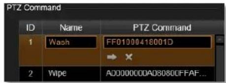
input the name, command and then click "Apply" to save it. You may also click "→" to execute it or "X" to clear it.
Set PTZ Preset Tour
Preset Tour is a preconfigured PTZ sequence that directs the camera to cycle through multiple preset points, including where to look and how long to look at each location. With this preset tour, your PTZ device can perform an automatic patrol to scan through your cared areas.
For example, a Preset Tour should include two or more preset points. Once a tour is initiated, the device will automatically point to the preset points based on the sequence and stay at that view according to the duration you set.
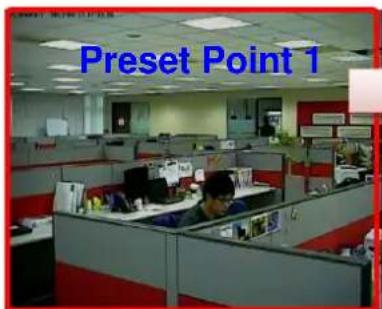
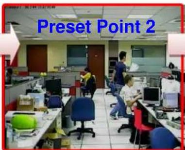
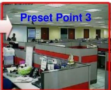
Before setting up Preset Tours, please make sure you have configured PTZ settings and set PTZ Preset Points. To start setting the Preset Tour:
-
Go to Setup page → Devices tab, select the device from Device List, and click Preset Tour tab.
-
In the "Tour List", as there is currently no existing tour, click "Add New Tour" to add one. The default tour name is "Preset Tour 1".
-
In the "Preset Points of a Tour" area, click "Add Preset Point" to add the number of points for this tour. The number of points may outnumber the actual preset points you set, for the same preset point might be gone through more than one time in a single tour. For each point, click in the "Preset Point" field to bring up the dropdown list, and select one preset point and define the dwell time which represents the time the device would stay in a certain view. Finally, click "Apply" to save the tour.
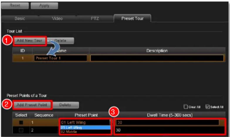
- After a tour is saved, it is available on Live View page→PTZ control panel.
Note
The preset points and tour set in NVR 3.0 are independent from those you set on device. If you have already defined certain preset points or tour on device, they will not be brought to NVR system. On the other hand, the settings on NVR 3.0 will not write to the devices.
Configure Fisheye Cameras
With hemispherical lenses, fisheye cameras generate images at up to 360-degree width, which can cover all four corners of a room or both sides of a long aisle. As the original image captured by wide-angle lens is much distorted, to suit most monitoring purposes, the Dewarping process is required to alter the uneven lines and shapes before the images are displayed. Nowadays, the fisheye cameras come in two types in terms of the image-correction capability:
- Fisheye Cameras with in-camera dewarping function
The dewarping takes place in camera before the video is output to NVR server. Since the image correction counts on the camera itself, NVR server will not bear much extra loading, which benefits the system requiring many of these fisheye cameras (e.g. ACTi KCM-3911, KCM-7911)
● Fisheye Cameras without dewarping function
These fisheye cameras output only original global images, relying on software algorithm processing provided by NVR sever to correct the images. They are suitable for a system with limited bandwidth, for NVR server processes and responds to User's ePTZ manipulation or demands for changing view modes immediately, without waiting for camera side to deliver a new frame (e.g. ACTi E96).
NVR 3.0 makes it possible to integrate both kinds of fisheye cameras into your system with the following advantages:
●Full support for all types of dewarped video stream output from fisheye cameras with in-camera dewarping capability.
●NVR's software algorithm can perfectly corrects the original fisheye images, generating 6 specific fisheye view modes from User's usual perspective.
- Based on user's instant request for changing view mode or PTZ view point, NVR server will process the original fisheye image and respond to the client individually. In this way, what a client sees on Live View will not affect playback, recording, as well as another concurrent connection.
●The virtualized ePTZ manipulation also allows User to dynamically explore any region of interest within the hemispheric view like operating a genuine PTZ device.
To make use of NVR's dewarping features for your fisheye cameras, please
1. Adjust Video Quality Settings
After the fisheye camera is successfully added, go to Setup page → Devices tab, select the device and then Video tab, make sure you set the Stream Mode as "FISHEYE" for a hemispheric camera (KCM-3911, KCM-7911). This is to make sure this hemispheric camera is outputting fisheye original video stream as a mini fisheye dome camera does.
2. Adjust Fisheye Display Settings
Select your Mounting Type, and then Default Fisheye Mode. For a Fisheye Mode containing panorama view, you may want to configure the Default Rotate X (width of view) and Default Rotate Y (height of view) configurations.
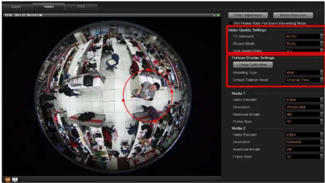
You may adjust the dewarped area by clicking "Image Calibration". In the edit mode, move or resize the red ring to define the dewarped area, and then click "Set" to save the setting.
| Fisheye Mode | Description | PTZ Navigation | |
| Original View | The very raw fisheye view  | Digital PTZ | |
| Dewarping | One large user-defined cropped area  |  | ePTZ |
| Panorama | 360-degree panorama view for ceiling mount 180-degree panorama view for wall mount    |  | Digital PTZ |
| Double Panorama | Two 180-degree panorama views  |  | Digital PTZ |
| Panorama /Focus | One panorama view Two small user-defined cropped regions  | 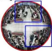 | ePTZ |
| Quad | Four small user-defined cropped regions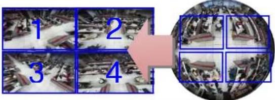 | ePTZ |
- After the configuration is done, remember to click "Apply" to save the settings.
Schedule Recordings
Unlike the traditional analog surveillance system, the IP surveillance system provides a target-oriented recording schedule for devices; the view of each device can be recorded based on your required time segments and event types. For example, you may have a camera installed on the office ceiling do continuous recording during work hours, and record only upon the triggers (incidents that detected by system) at night. In this way, the system does not waste disk space storing meaningless parts, and you save lots of effort browsing playback for specific events.
For the device's recording schedule, NVR 3.0 supports Schedule recording and Event recording modes, which are set up on a week-based timetable; the event-handling schedule can also be configured on it. This section describes how to setup the recording schedule for the IP cameras / video servers.
Configure the Recording File Properties
Before setting the recording schedule, you may define (1) where the recordings are stored, (2) how long an event recording is and (3) how long a recording file will be kept in the system.
- To set the saved recordings folder, go to Setup page→Storage tab, make sure you have assigned the disk drives to store recorded files. For related recording settings, please refer to Storage Management on page 109.
- To define how long an event recording is and the recording's lifecycle, go to Setup page→Schedule tab, and select the device from Device List, and then a week schedule will appear on the right. Configure the recording file related settings. The settings below will make an event recording as long as 5+30 seconds, which will be kept on server for 30 days.
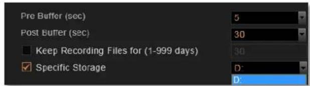
| Field Name | Description |
| Pre-event Recording Buffer (sec): | The NVR server keeps a short cache of video received from the devices. If an event is triggered, the NVR server will automatically store the pre-event buffer along with the recording of the event itself. Available choices are 0, 3, 5 seconds. |
| Post-event Recording Buffer (sec): | This will determine how long after the event is triggered should be included in the event recording file. Available choices are 10, 30, 60, 120, 180, and 300 seconds. |
| Keep Recording Files for (1-999 days): | The NVR server will keep recording file of specific device for the number of days you set here. The default value is 30, and if you want to modify it, please check the box to start configuring it. Available value is among 1~999 days. |
| Specific Storage | You can assign a dedicated storage disk for a camera. By enabling this option and assigning a specific disk, the video footages will be recorded only to this selected disk rather than those you select on Setup page→Storage tab. Please remember to configure the storage-related settings for this specific disk on Setup page→Storage tab after you enable this option. |
Tip
How to make proper storage arrangement
In NVR 3.0 system, there are two file-deleting mechanisms you can use based on different needs. If both rules are set, the threshold reached earlier will execute the deletion first.
- "Keep Recording Files for (1-999 days)" – Set this rule if you have more concern in how long the recordings are kept, especially when you don't want the old recordings to stay longer in the system than a certain period.
- "Reserve space" in the Disk Drive List on Setup page →Storage tab - If the disk space is more critical in your system, please give an approximate value here, the system will always reserve this amount of space to store the newer recordings.
Given that you set the Reserve space as 30G, while Keeping Recording Files setting is 5 days, certain recording file will be deleted when it has been kept on disk for 5 days, despite that there is still plenty of available disk space.
Before setting up the rules, you can make use of a handy storage calculator provided by ACTi to find out the estimated storage your system requires on ACTi corporate website: http://www.acti.com/project_planner
Set the Schedule
Here you can configure camera's recording schedule on 7 days / 24 hours basis. The schedule is split into segments of 20-minute-length. By default, once a device is added to the system, its schedule is automatically set to full time schedule recording and event handling. You should configure it according to your system plan.
Go to Setup-Schedule tab, on Schedule Setting panel:
- Select the recording mode from "Recording Mode Bar"
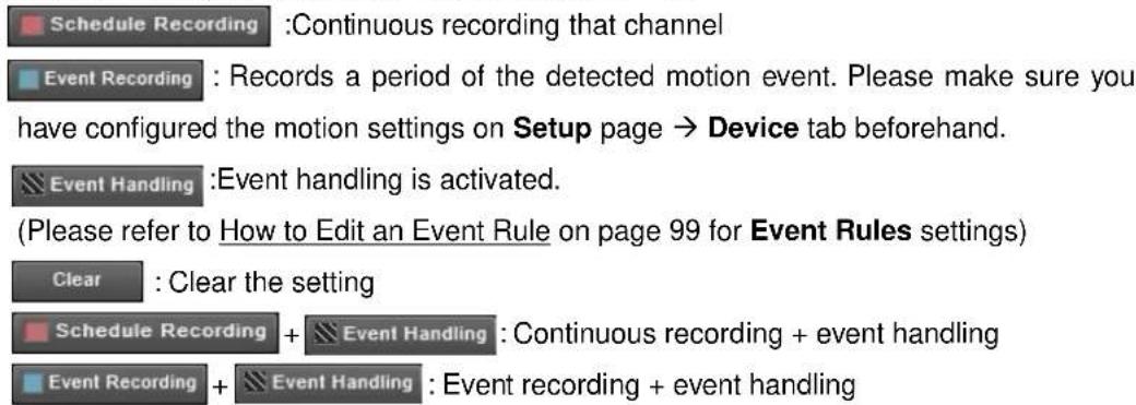
- Click and drag over the "Time Track" to set time period.
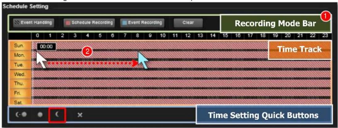
Use Time Setting Quick Buttons to Set the Time in One Click
Select the recording mode, then click one of these buttons to apply the mostly-used time settings.
Click to apply schedule for all day.
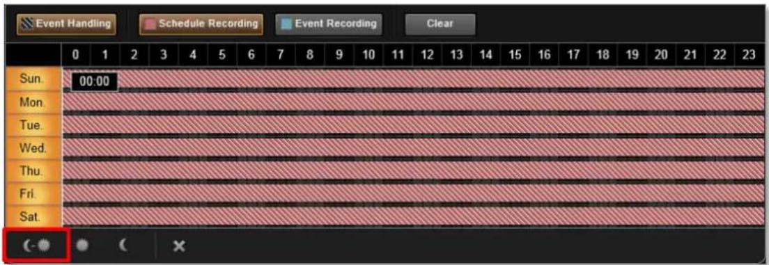
Click to apply schedule from 06:00 to 18:00 every day, with the settings for the rest of the time track being cleared.
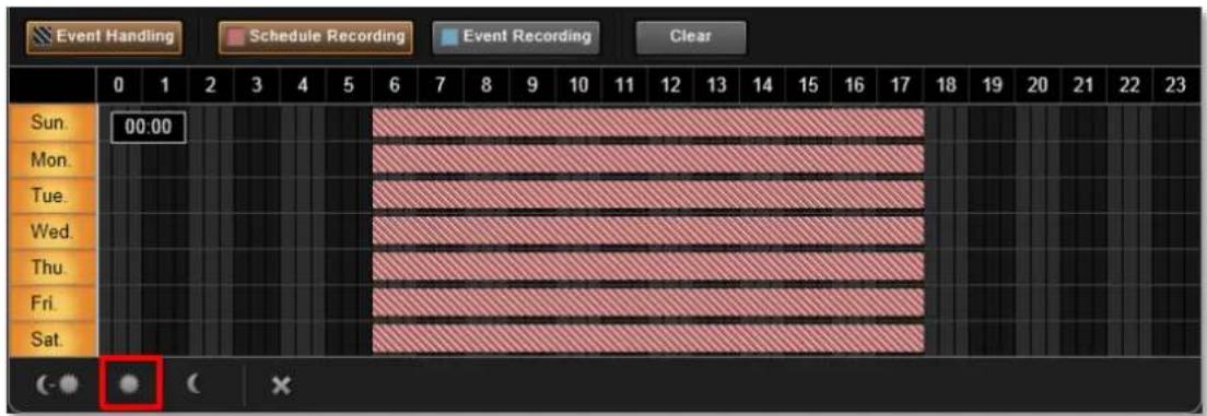
Click ☐ to apply schedule from 18:00 to 06:00 every day, with the settings for the rest of the time track being cleared.
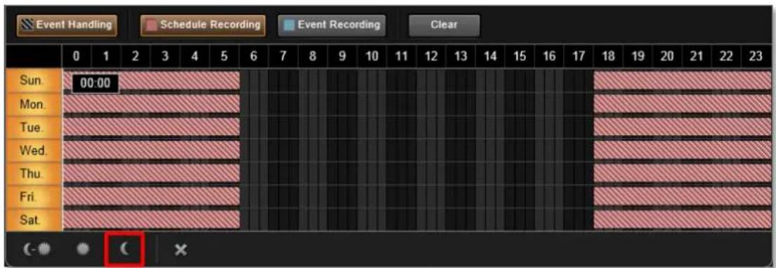
Click ✗ to clear all schedule setting in this device.
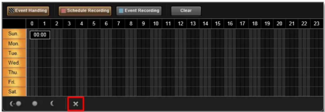
Lock Specific Days
Clicking the day of the week will lock/unlock that day from schedule setting. You can shield schedule on a certain day from being changed by changes in other weekdays. You may easily set just the weekdays or the same time over the same week this way. To do this:
- Click the days to shield them.
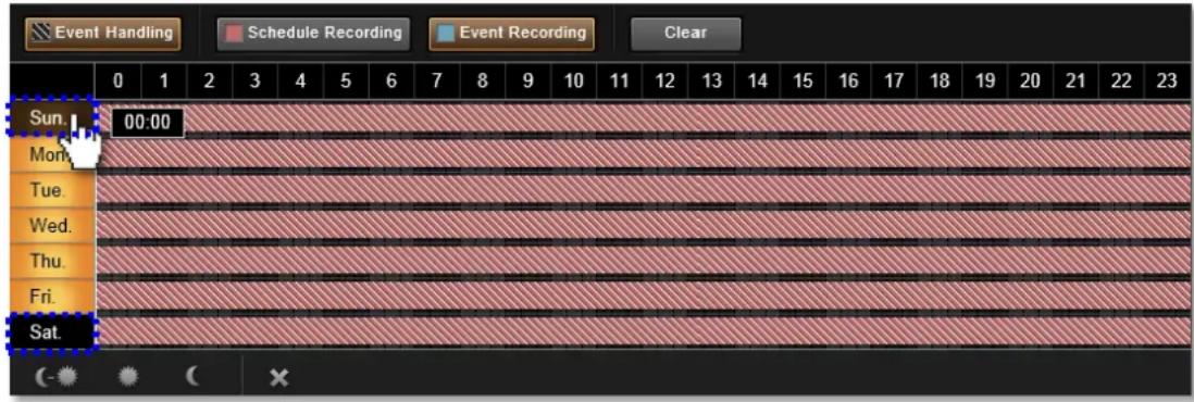
- As you drag any settings over the time track, it will not apply to those shielded days.
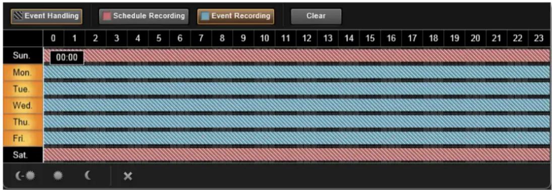
Copy an Existing Schedule to Others
With plenty of devices in your system, it happens that you want to apply the same schedule to multiple devices. After creating a schedule for one device, you can copy it to other cameras.
- Go to Setup page → Schedule tab, on Device List, select the device you want to copy schedule settings from.
- Click the "Copy" button.
- On popup window, select target devices you want to copy schedule settings to.
- Click the "Apply" button.
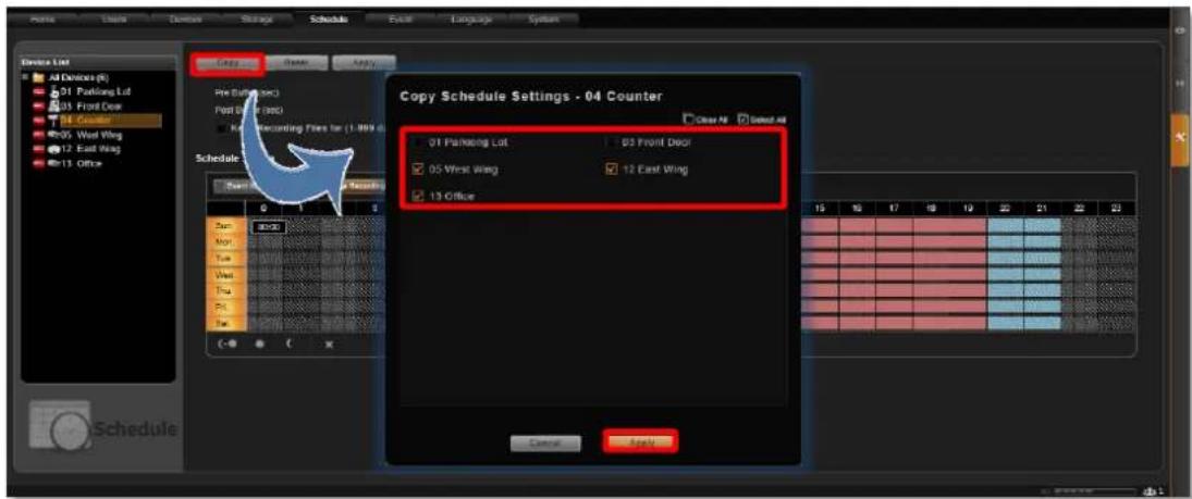
To check the result, go to Schedule tab, click All Devices on Device List.
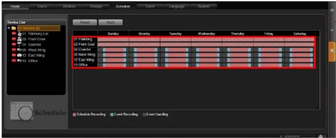
View the Entire Recording Schedule
On Setup page → Schedule tab, click All Devices on Device List, an overview of all device schedules will be listed on the right.
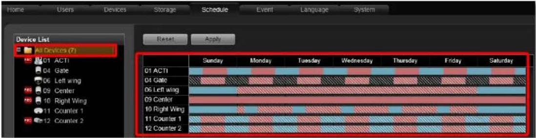
The below list explains the status of different bar patterns:
| Icon | Recording Function Description |
| Schedule recording. During this period, device view will be recorded continuously. | |
| Event handling. During this schedule, the event rules you set are active. | |
| Schedule recording and Event handling are both active during this period. | |
| Event recording. During this period, only detected events (e.g. Motion/PIR) will be recorded . | |
| Event recording and Event handling are both active during this period |
How to Know if the Recording is Proceeding?
As the recording is taking place, you can observe the status on the All Device list. There will be an icon REC appearing in front of the device. In Playback, you can drag the playback bar to current time position to check the latest recording.
Event Management
When something happens on camera site, such as someone walks by, the door opens or closes, a fire breaks out or the sun goes down – these are all Events. Events which occur in the environment or were preprogrammed in the camera may be used as Triggers. Triggers cause the device to react with Responses. The link between trigger and response is governed by Event Rules. Event rules become active or inactive based upon a weekly Schedule. Each event rule detects one specific trigger and may initiate multiple responses. An example rule would be for NVR to send e-mail to alert the supervisor (Response 1) and trigger alarm (Response 2) when motion detection from camera is triggered (Trigger) during the event handing active period (Schedule).
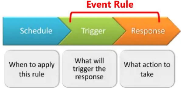
flowchart
graph LR
    A["Schedule"] --> B["Trigger"]
    B --> C["Response"]
    D["When to apply this rule"] --> E["What will trigger the response"]
    F["What action to take"] --> G["End"]
How Does NVR Handle Events
In NVR 3.0, each device can be involved in several event rules. As different device models possess various capabilities, the supported event trigger types would vary. For example, a PIR built-in camera can execute a PIR-triggered event rule, while this option is not provided to other models without this feature; similarly, the supported response types would vary by device models, like Goto-preset behavior can only be executed by PTZ devices. The below chart shows NVR server supported Trigger types and Response types. Once a device is added to NVR server, the server would create empty rules with compatible trigger types for you to configure.
| Trigger Type | Response Type |
| Video Motion Detection | Focus Channel in Live View |
| Digital Input | Make Device Pan/Tilt/Zoom |
| PIR Detection | Audio Alert |
| Video Loss | Trigger DO Device |
| Video Recovery | Execute URL Commands |
| Network Loss | Upload Snapshots to FTP |
| Network Recovery | Email Notifications/ Snapshots |
How to Edit an Event Rule
- Go to Setup page → Event tab. All the editable event rules are listed in the device ID order.
- Select a device from the Device List on the left. Based on the trigger types this device supports, the corresponding events rules are listed accordingly on the right. In this example, this selected camera model supports three motion detection regions, and hence three MD trigger event rules are available.
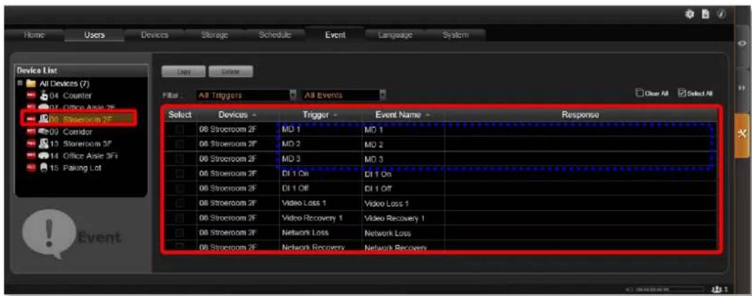
- Highlight the rule you wish to edit. Click in the "Event Name" column to edit the event name, and then double-click the "Response" column to edit the response action.
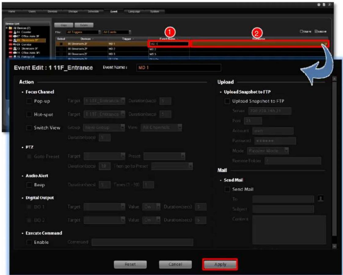
You can enable multiple responses by first checking the box(es) to enable the items:
| Action Items | Function Description |
| This kind of action will focus your attention on the channel when triggered.Pop-up:Brings up event pop-up instant playback window of selected channel upon trigger. You may also define the display duration of video on the window.Hot-spot:Displays video in Hot-Spot window (red flashing frame) upon event. You may also define display duration of video on the Hot-spot window.Switch View:The current Live View will be switched to another one for a while. To enable this option, you will need to customize and save Views on Live View screen first. You may also define duration of the temporary View. OnlyPublicViewsare selectable for Switch View event rule.Hot-spotandSwitch Viewresponses cannot be executed at the same time. | |
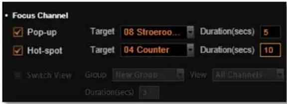 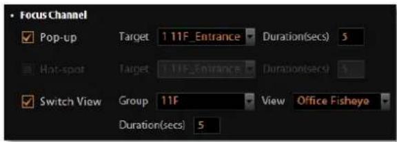 | |
 | Upon being triggered, specific camera can make PTZ movements like going to specific PTZ presets as responses. You may set both the start / end point and the duration.This action is only available when you have set the preset points. |
 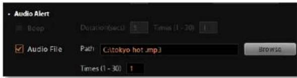 | Makes NVR play beep sound or an audio file for a number of repetitions.OnNVR3 Workstationclient computer, you can upload a WAV file or an MP3 file as the alert sound, and set how many times this audio file is played when the event occurs. (This NVR server has to be already onServer Site list, refer toG.Server Name/Server Sites Liston page 49 for how to save a server site). Please note thatBeepandAudio fileresponses cannot be executed at the same time. |


Set the DO to become ON or OFF upon trigger, only the devices supporting DO functions can be the target devices.
Enable NVR to execute a certain command upon this event. You can use it to integrate NVR's event handling with other programs. Enter the path of the command to be executed upon event.
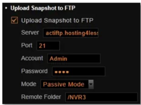
Enable NVR to upload snapshots to a FTP site upon this event. The default FTP settings can be set in advance in Setup page→System tab→Settings → FTP Settings. You may set another FTP destination here for this single event. Please also make sure the FTP server setting is correct and the folder access rights are properly configured.
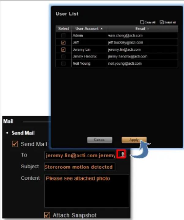
Enable NVR to send e-mail notification via SMTP server. The default SMTP and sender's e-mail settings can be set in advance in
Setup page →System tab→Settings →E-mail& SMTP Settings.
- Type one or more recipients' e-mail addresses in "To" column (if more than one, please separate them by ";; symbol) or click the 📁 icon to select recipients from existing NVR User list. The E-mail address should be set in advance (in Setup page→Users tab→Users) for an NVR User so that it can be selected in this list.
- Edit the e-mail subject and content.
-
Choose to attach a snapshot or not. If event trigger type is Video Recovery or Network Recovery, this function is disabled.
-
After configuring the actions, click "Apply" to save this response.
-
Go to Setup page→Schedule tab and set the Event Handling schedule for this device. Event responses will only be triggered when the trigger time falls within either the Event Handling recording or the Event Handling with Schedule recording period.
-
To check if this rule is successfully set, please make sure you have properly configured the involved (1) triggering side settings like Motion Detection Regions or DI, (2) response side settings like PTZ Preset Points, SMTP Server and E-mail Recipients, FTP Server or DO. Then set the Event Handling schedule for current time and trigger this rule.
Note
- Sending e-mail, Uploading snapshot to FTP and Executing command actions are executed on the server computer, not from the client computer.
- There must be video stream from device when the event happens for event responses to work.
- Internet Explorer browser may become unstable due to frequent pop-up instant playback windows, please avoid setting the "Pop-up" action as the event rule for a device which is too frequently triggered. The next server version v3.1 will improve the program efficiency with Internet Explorer browser.
Manage the Event Rules
Event List panel gives an overview on event rules set on the NVR server. Go to Setup page → Event tab → select All Devices on the left. As the entire available rules of all devices are listed here, you may want to sort out some of them from the long list.
View the Event Rules
To sort by Device name, Trigger type or Event Name, click the titles to list the entries in ascending or descending alphabetic order.
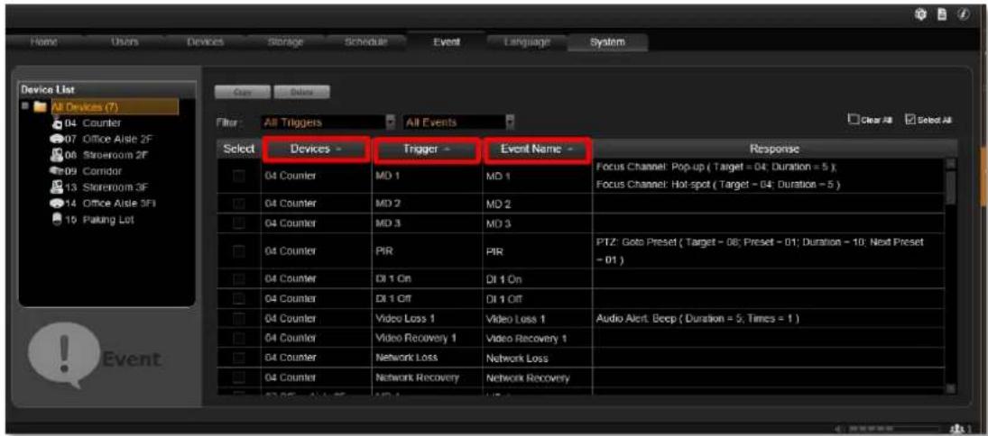
To filter out the configured events, select from the "All Triggers" dropdown list; or filter by the event type by selecting from the "All Events" dropdown list.
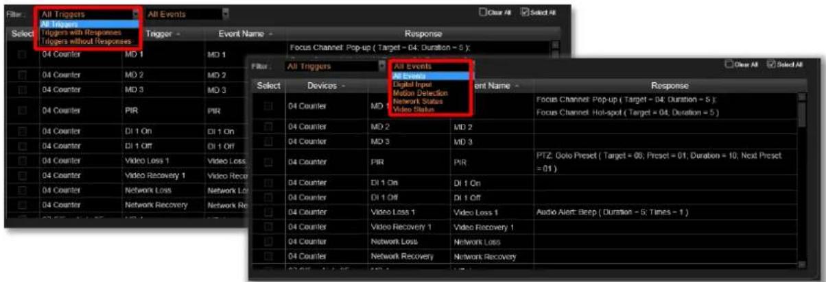
Delete the Event Rules
On Event List, select the rules you wish to delete, and then click "Delete" to clear this rule.
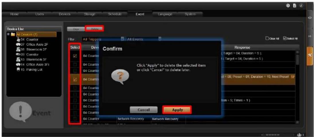
How to Setup SMTP Settings for Event Rules
NVR 3.0 supports e-mail notification for Event Handling sent through an SMTP server. You can specify the e-mail and server settings here.
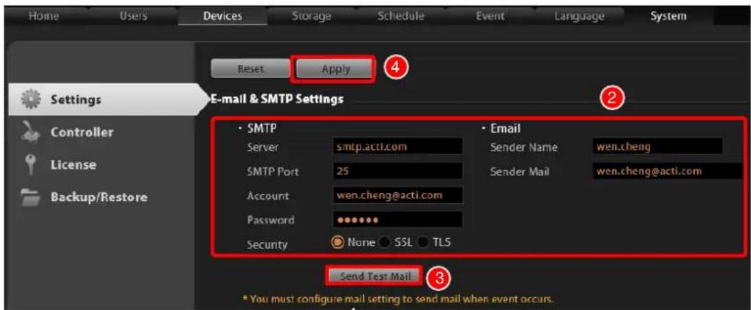
- Go to Setup page→System tab→Settings → E-mail& SMTP Settings.
- Fill in each of the following fields.
| Field Name | Description |
| Server | Input the sender's SMTP server address. Only alphabets, numbers, and the symbols (.), (_), (-) are valid. |
| SMTP Port | Set the SMTP port, allowed value is from 1~65535, default is 25. |
| Account | Input the name of the SMTP server account. Only alphabets, numbers, and the symbols (@), (.), (_), (-) are valid. |
| Password | Input the password of the SMTP server account. Only alphabets and numbers are valid. |
| Security | Certain webmail providers provide the SSL/TLS-encrypted SMTP connections to secure your data when sending/receiving e-mails. Please check if the SMTP connection settings you use (especially the SMTP Port) now require enabling either SSL or TLS. |
| Sender Name | Input the name or title of the sender. You may input a name different from the account name. |
| Sender Mail | Input the sender's e-mail address, which should the same account you set for SMTP server. |
- As all necessary information is filled in, click "Send Test Mail" to try sending an e-mail according to your settings, and then log in to your SMTP server to check incoming e-mails. If the test mail is sent successfully, NVR server is ready to send out e-mails.
- As the settings are confirmed, click "Apply" to save.
How to Setup FTP Settings for Event Rules
NVR 3.0 supports uploading snapshots to FTP servers for Event Handling.
You can specify the e-mail and server settings here.
- Go to Setup page→System tab→Settings → FTP Settings.
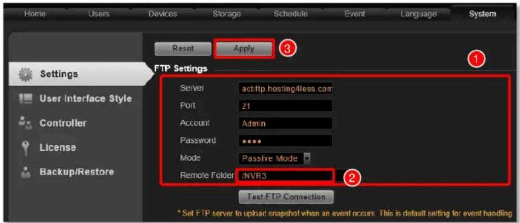
- Fill in each of the following fields.
| Field Name | Description |
| Server | Input the FTP server address. Only alphabets, numbers, and the symbols (.), (_), (-) are valid |
| Port | Set the FTP port, allowed value is from 1~65535, default is 21. |
| Account | Input the name of the FTP server account. Only alphabets, numbers, and the symbols (@), (.), (_), (-) are valid. |
| Password | Input the password of the FTP server account. Only alphabets and numbers are valid. |
| Mode | The FTP works in two very different manners, Active mode and Passive mode. If your FTP server is behind the firewall or a NAT router, you have to us “Passive” mode. |
| Remote Folder | Input the upload path of the file. Default will be “/” to represent the root folder. |
-
As all necessary information is filled in, click "Test FTP Connection" to test the connection. If NVR server pops up a "Testing FTP connection was successful" message, NVR server is ready to upload to this FTP.
-
As the settings are confirmed, click "Apply" to save. The FTP settings here will be default for every event rule.
System Log
The activities performed by logged-in Users are recorded on server as System Log. With the access permission, a user may view, search and export this record for analysis or investigation. This section will provide the instructions on how to read and search data in the system log.
“System Log” is one of the resident buttons on top of NVR server user interface, click it to enter search window.
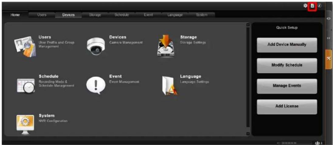
Define Search Time
You need to first define the time of the logs you would like to search for. On Search Time bar, define the date and time. Default is your current client time.
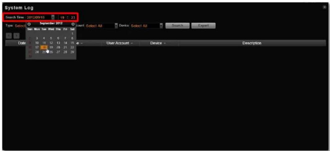
Choose Log Type
You may filter the logs by Type, User Account, and Device by selecting from dropdown list, then click "Search". By default, all types are selected.
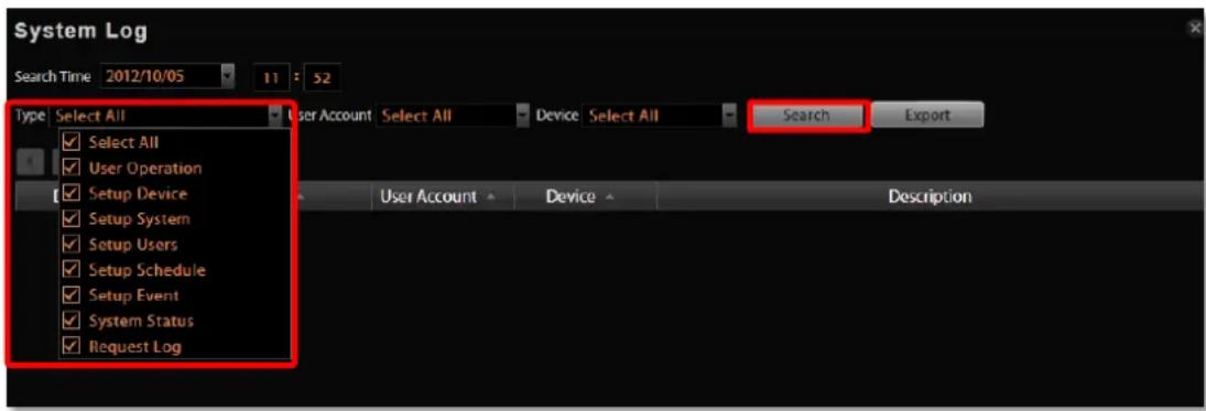
Read the Log
The search result will show 1000 records before and after your query time. You may click the pagination buttons to navigate earlier or later records. If there is an icon on the right top corner of an entry, click it to view the full description content.
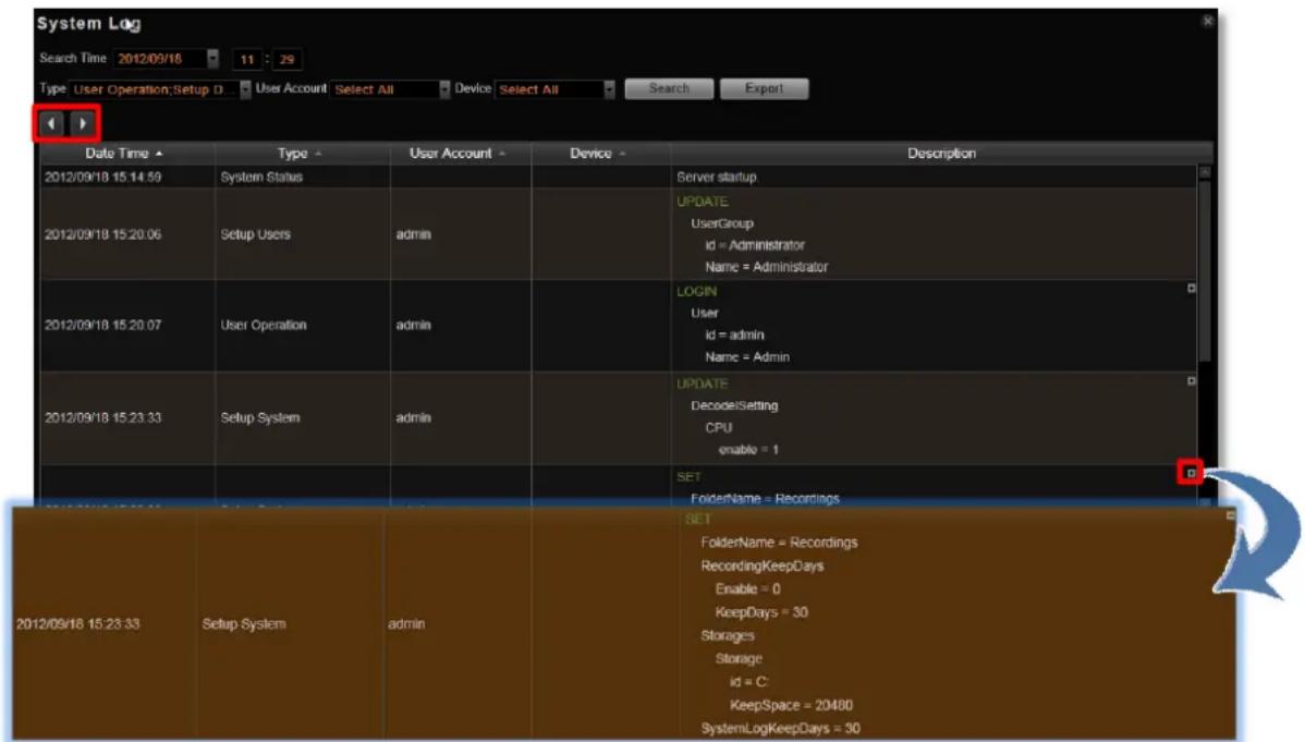
A log entry contains several kinds of information including Date Time, Type, User Account, Device and Description. Check Type and Description fields to know what the user has done or what happened to the whole system. In Type field shows what major functions user engaged in, in Description field narrates how the change was done (in green font color, uppercase) and the result (in white font color).

The following user behaviors are recorded in NVR server:
| Type | Description |
| User Operation | Login, Logout, Manual Record,Trigger DO |
| Setup System | Recording Configure, Storage System Setting |
| Setup Users | User – Add,Delete,ModifyUser Groups – Add, Delete, Modify |
| Setup Schedule | Modify |
| Setup Event | Modify |
| System Status | Server start up, disk is full, disk is not found, disk is available |
| Request Log | Time, source ip address |
Note
If the pagination button appears to be disabled, that means no more records found on NVR server. By default, the server will keep the logs for 30 days. If you wish to adjust the period, please go to Setup page → Storage tab, in Recording Settings section, key in the value in this field: Keep System Log for (1-999 days) 30
Export the Log
Click "Export" button to export the log as .csv file. You can specify the time duration, engaged User Account and devices of the logs, and click "Apply".
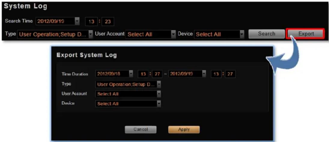
Storage Management
This section describes how to manage storage space in NVR. Please note that this section only deals with the overall storage rules, and not storage of individual channels.
Please note that as NVR continuously writes and deletes file from the disk drive, using a removable disk may risk losing recording when device is removed while being accessed.
Go to Setup page→Storage tab.
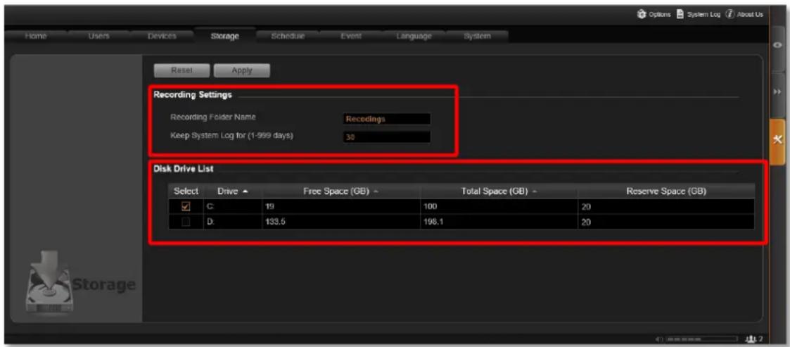
Change Recordings Folder Name
In "Recording Settings" section, you may change the name of video recordings folder. The video files are saved in a folder named "Recordings" under hard drive root directory. You may change the name here.
Set System Log Lifecycle
System Log is the record of User activities and events that took place on the server. In "Recording Settings" section, you may set how long this record is kept on the server. Default is 30 days.
Set Hard Drives for the Recorded Files Deletion Rule
- Disk Drive List displays the detected hard drives in the NVR server. You may select the storage location of the recording files and set the deletion threshold. By default, the NVR server will select C drive as storage location. It is strongly recommended that, for GNR, you select other hard drives as the storage disks rather than Drive C.

- After selecting the disk drive, please set the deletion rule. There are two ways to delete recordings, and when both are active, the NVR server will start to delete old files when any of the criteria is met.
(1) Reserve the recordings for a number of days, and delete files older than this period by 1 GB at a time. Please go to Setup page → Schedule tab to set it.
(2) Reserve the recordings until the disk is almost full, and then delete the earliest recording files by 1 GB at a time. The NVR server will delete old files when available space is lower than Reserve Space you set in Disk Drive List.
When setting the deletion rule, please input a number in Reserve Space which should be smaller than your current Free Space.
| Item | Description |
| Free Space (GB) | Currently available space of the chosen disk drive. |
| Total Space (GB) | The total volume of the chosen disk drive. |
| Reserve Space (GB) | This is the amount of space to be reserved for the whole system.Once the free space is used up as to reach the limit of reserved space, the system will delete the earliest recordings. The “Reserve Space” should always be smaller than “Free Space” |
- When finishing settings, click "Apply".
Manage User Groups/ Users
The User Groups/Users page allows you to (1) manage the access permissions of different user groups, (2) add users to or delete them from user groups, (3) and assign users to specific user group. This chapter will take you through these settings.
Access Permissions
In NVR 3.0, the access permissions are managed by User Groups. User Groups defines what functions and devices are allowed for each user. Different User Groups will have different access rights in terms of permitted operations with each device like Live View, Playback, and NVR server management operations like Device Setup, Schedule Setup, Event Setup and System Setup. For example, an Administrator User is allowed for all the operations in NVR, while a standard User may only be permitted to do Live View and Playback with limited devices.
The chart below displays different employees as NVR Users and their access rights in this system:
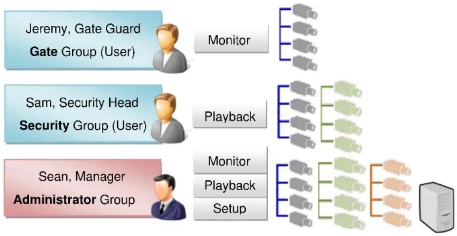
flowchart
graph TD
    A["Jeremy, Gate Guard\nGate Group (User)"] -->|Monitor| B["Server"]
    C["Sam, Security Head\nSecurity Group (User)"] -->|Playback| D["Server"]
    E["Sean, Manager\nAdministrator Group"] -->|Monitor| F["Server"]
    E -->|Playback| G["Server"]
    E -->|Setup| H["Server"]
Overview
Go to Setup page →Users tab. There are two sections to manage User Groups and Users individually.
User Groups: To setup user groups and its permissions for device and functionalities.
Users: To manage user accounts and configure user information.
ACTi NVR 3.0 has integrated Microsoft Active Directory® service to provide network administrators a more convenient choice for user management. Active Directory is a directory service built in Microsoft Server products to manage user identities and privileges within the
domain network. As ACTi NVR 3.0 runs on a server computer logged on to the same domain with Active Directory server, you can import a user account or a group from those concurrently existing in Active Directory into NVR server. In this way, the user identification is processed by Active Directory centrally; there is no need for NVR administrator to maintain user accounts as long as they are under management of Active Directory service.
User Groups
You can specify access permissions to each device for a whole user group. This user grouping can save you significant amount of works if you have multiple users performing similar tasks and acting as similar roles.
There are already two default User groups
● Administrator: With full permissions in the NVR.
- User: With the permissions to watch all camera live view and playback.
You can create a new user group on NVR server or import an existing group from the Active Directory database within your domain.
- Select User Groups, click "Add" and then choose the group type:
- Add a new user group:
Insert ID, group Name and group Description, your input in the Name field will be the name of this User group. Click "Apply" to finish.
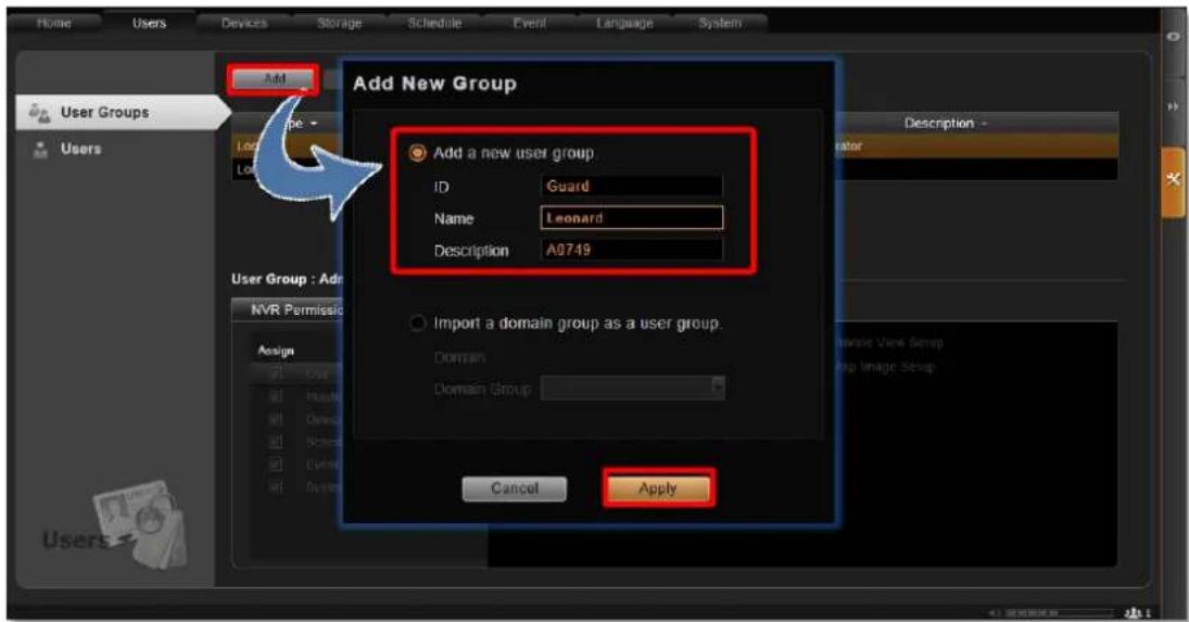
- Import a domain group as a User group:
Choose an existing user group from your domain, and click "Apply" to finish.
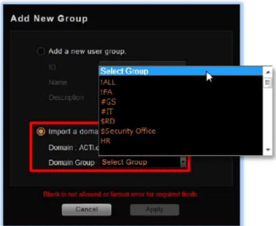
The domain users within that group will all be added to NVR server at the same time. To view the whole users within this group, please select Users and enable the "Show users in domain groups." The account information of these domain users, unlike those user accounts you add one by one to NVR server, are not editable on Users page.
| Show users in domain groups. | ||||||
| User Type - | User Account - | User Name - | Password | Email - | Group Name - | |
| Customized User | admin | Admin | ********** | Administrator | ||
| Domain User | Deckard Gain | Deckard Gain | Deckard.Cai@acti.com | Security Office | ||
| Domain User | John Bourne | John Bourne | John.Bourne@acti.com | Security Office | ||
| Domain User | Steve Lin | Steve Lin | Steve.Lin@acti.com | $Security Office | ||
| Domain User | Joyce Holiday | Joyce.Holiday | Joyce.Holiday@acti.com | General Service | ||
Domain users added as a whole group
- Assign NVR Permissions for created group. This will define what functions this User group is allowed to access. By default, a new User group will initially be allowed to access only Live View page and Playback page, but without any permission to any device setting, so you will have to assign the device permissions later.
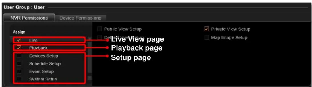
- Assign Device Permissions for created group. This will define which devices this User group is allowed to access. If this User group is allowed to access all newly-added devices, check "New Device Default" and edit the permissions, these default settings will be applied to any device added in the future.
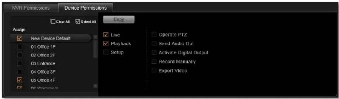
You may copy the Device Permissions Settings to other devices. Click "Copy" under Device Permissions tab to bring up the target device menu, check the target devices, and click "Apply".
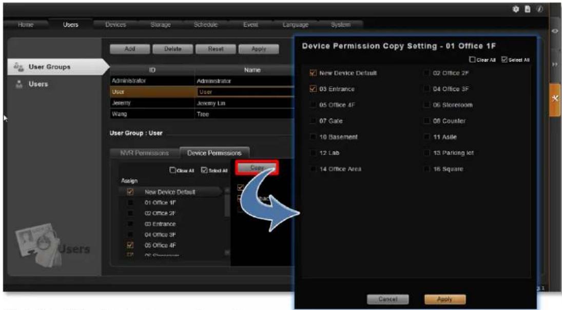
Click "Apply" on the top to save the settings.
Add Users
To create a user account with on NVR server.
-
Select, and click Add button.
-
Select User Type as Customized User or Domain User.
- Customized User: an account created and managed on NVR server only. You will input an account name, its password and e-mail address for this User.
- Domain User: an account that already exists in Active Directory database within the domain. Since this is an existing account in your domain, you will have to select this account from Account dropdown list.
-
Insert user account, name, password, and the account mail (For Customized User).
-
Assign this created user account to a specific user group.
-
After you click "Apply", this new user will be added to the list on the top.
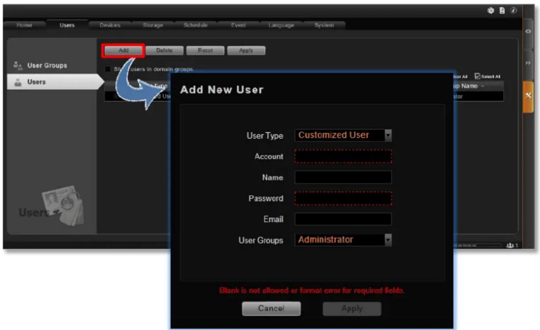
Note
NVR server provides a procedure to help Users who have forgotten the password retrieving the original information, which relies solely on the "e-mail address" authentication. It is strongly recommended that you input an e-mail address that this User has access to when you establish the User account. To update the e-mail address of an account, go to Setup page→Users tab →edit "E-mail" of an selected User account; the Users can also update the e-mail addresses themselves after logging in to NVR on Live View page →
Update Profile
Note
Account /Password Rules
- Account and Password fields allow alphabets, numbers, and symbols except the following: / \ [ ] : ; | = , + * ? < > "
- In Account field, for alphabets, the input will be recognized as lowercase letters. Space is only allowed between characters; the space in the beginning or at the end will be deleted as it is saved.
- The Password field is case-sensitive, and the space is allowed.
Note
Admin is the default user account and belongs to "Administrator" user group. Hence, the user Admin and the group Administrator cannot be deleted; it possesses full permissions to all devices and NVR settings.
Domain Users Management
As NVR server computer is logged on to a domain Active Directory, it can import a user account from Active Directory.
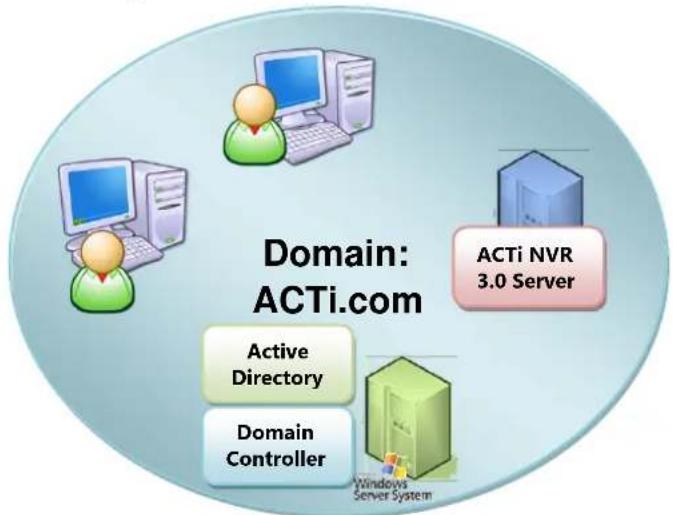
flowchart
graph TD
    A["Active Directory"] --> B["Domain Controller"]
    C["Windows Server System"] --> D["ACTi NVR 3.0 Server"]
    E["Computer"] --> F["Computer"]
    G["User Icon"] --> H["User Icon"]
This type of User account is "Domain User". Upon being added to NVR server, the User properties stored on Active Directory database including (1) account name (2) e-mail address will be imported to NVR server.

Whenever a domain User client tries to log in to NVR server, NVR server will first verify if this account exists in NVR server database, and then have Active Directory verify the user account and password.
As Active Directory owns the privilege to create, edit and delete domain users, the Domain User's account and password are not editable through NVR user interface but via Active Directory Administrative Tool.
Customize Views
After all devices are configured, you may start customizing the views for different users and purposes. This chapter will teach you how to add video source, arrange the channels and manage live view layouts.
In NVR 3.0 system, a View refers to the layout where the live images of Cameras or Maps are placed in proper positions to suit the monitoring purpose. This is very similar to a camera group, which often consists of cameras in the same physical location. For example, a View named 11F Emap & Camera may contain the 11F floor plan and the cameras actually placed on 11F.
On NVR Live View, a saved View not only remembers (1) layout style, (2) which channel to display which camera, (3) but the fisheye view mode (for fisheye cameras only.
Live View interface overview
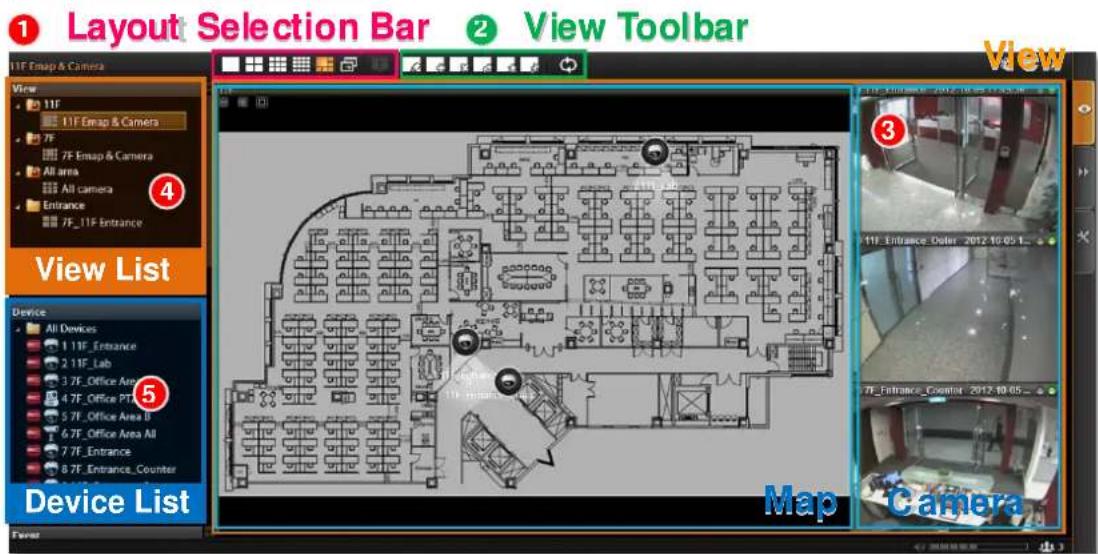
- Layout Selection Bar: Provides 24 options for layout styles.
- View Toolbar: Provides functions keys for editing.
- Channels: Each channel window may display a camera view or a map. In edit mode, you can adjust the channel size at will.
- View List: All the saved Views are shown here. On Live View, you can go to → View Manager to group and manage these views (refer to Manage the Views on page 124).
- Device List: In edit mode, drag camera from here to your desired channel.
Step 1: Create a New View
On View Tool Bar, click the Create View button ☐, input the View Name, add a New Group for this View and decide whether this group is to be Public or Private, and then click "Apply".
●The views under Private View Group are only available to the User who created them.
●The views under Public View Group are open to every User.
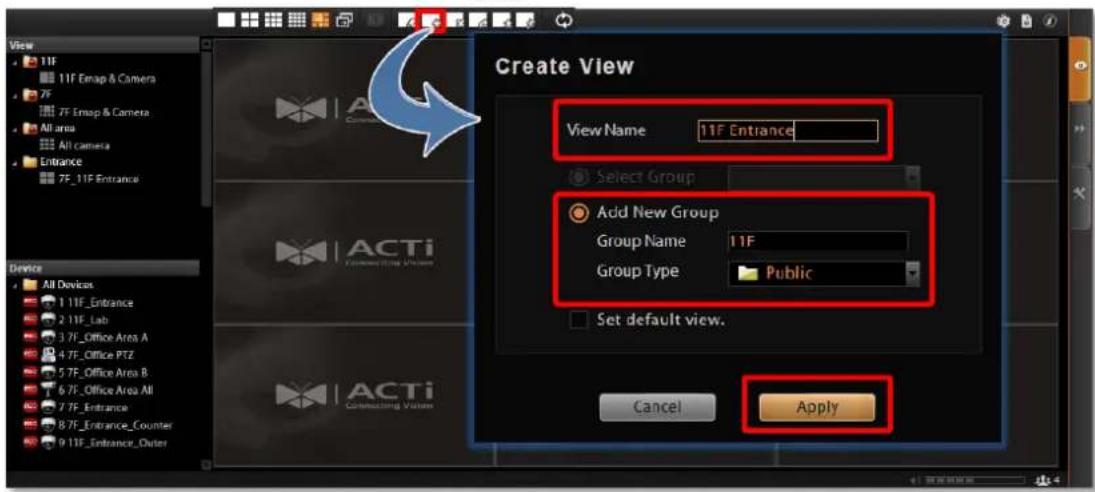
Step 2: Enter Edit Mode
On View Tool Bar, click the Edit View button ☐, this view will turn into edit mode. In edit mode, you may add a video source to a channel, and adjust the channel size.
Step 3: Select a Layout
On Layout Selection Bar, click the Expand button to find all provided layout styles. Select a layout that is perfect for your required channel number and ideal arrangement.
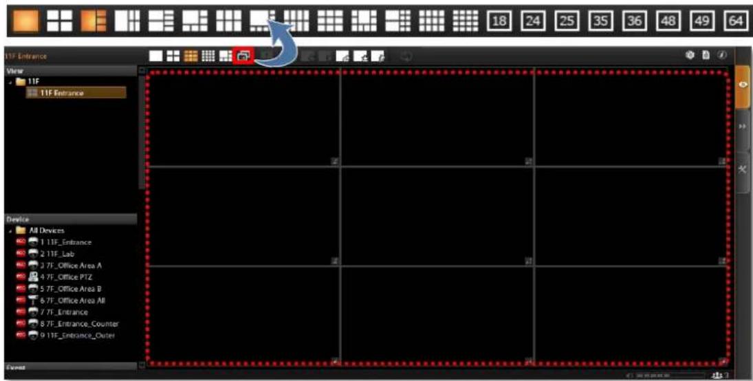
Step 4: Add Video Source
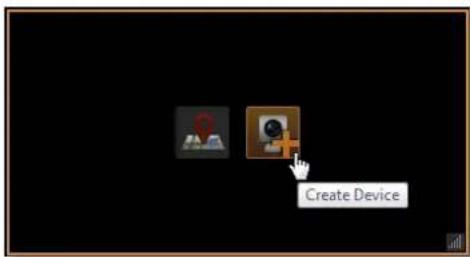
In edit mode, move the mouse over the channel and click 📄. You may also directly pull a camera from the Device panel to your desired channel.
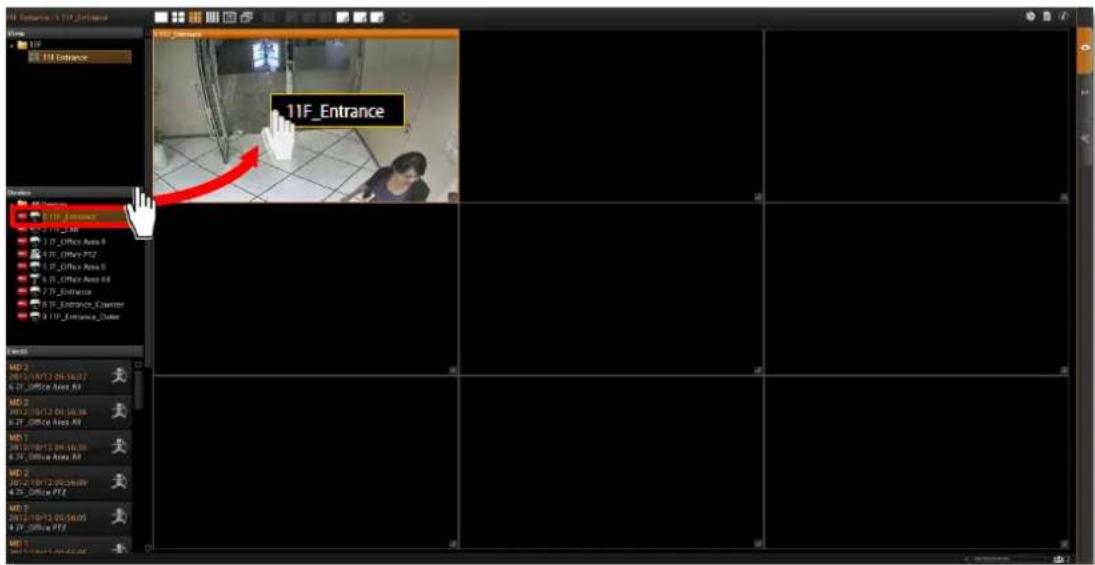
- Remove the camera view: right-click on the channel and select "Remove".
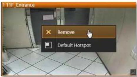
Step 5: Add a Map
By adding a map, you put a picture on the channel, where you may place camera icons to make it an "e-Map.
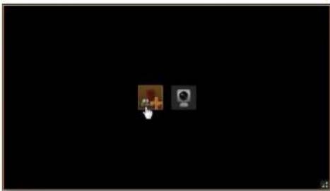
natural_image
Two small icons on a black background, one with a cursor pointing at a brown square and the other with a camera (no text or symbols)In edit mode, move the mouse over the channel and click 📄 to upload a map. Please input the Map Name, select the image location (file format must be JPG) and click "Apply".
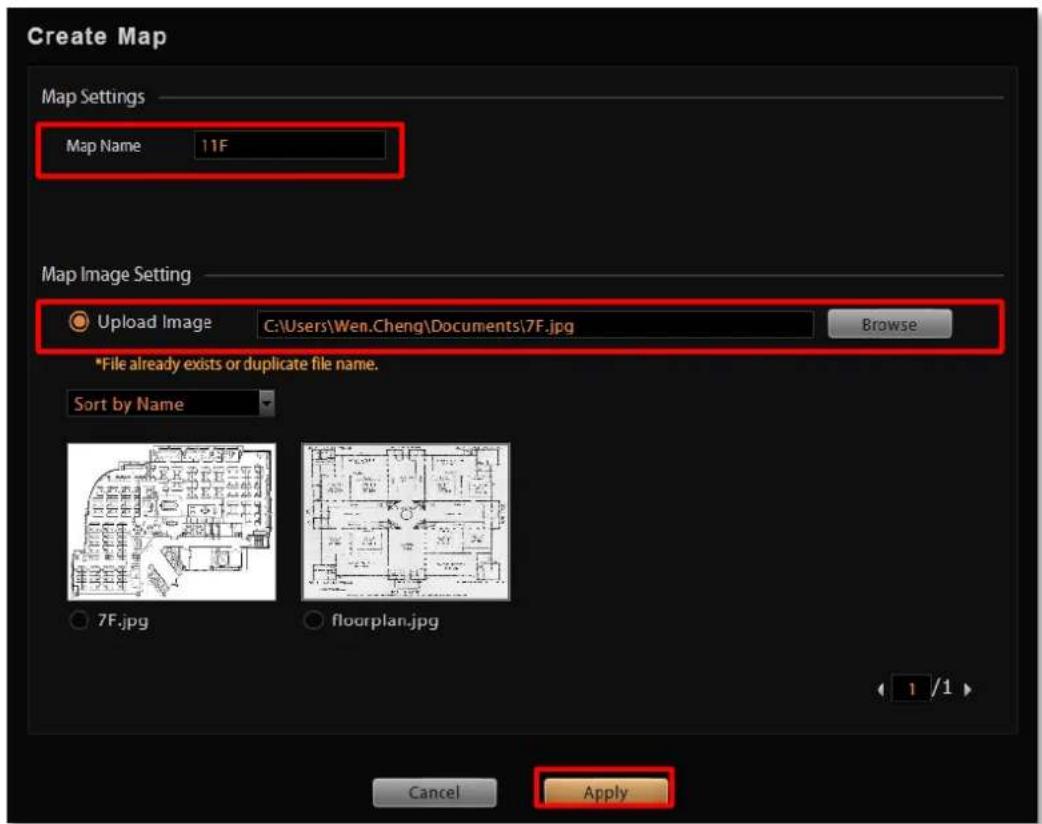
●Map brightness:
To change the map brightness, right-click on the map, select
"Map Mask" and the brightness percentage level.
| 0% | 10% | 20% | 30% | 40% |
| 50% | 60% | 70% | 80% | 90% |
- Map size:
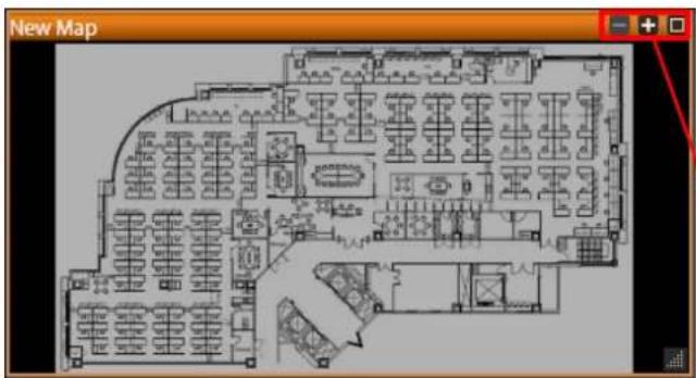
By default, the map will be displayed in its original size. Use the button s on upper right to adjust the map size.

Enlarge to fill channel height

Original image size

Zoom in

Zoom out
- Edit map title:
The map title will be shown on channel title bar. In edit mode, right-click on a map channel and select "Edit Map Information"
- Remove the whole map:
Right-click on the map and select "Remove".
- Manage maps:
All the uploaded images are managed under Map Image Manager. On Live View screen, you may go to → Map Image Manager to view, upload or delete the maps.
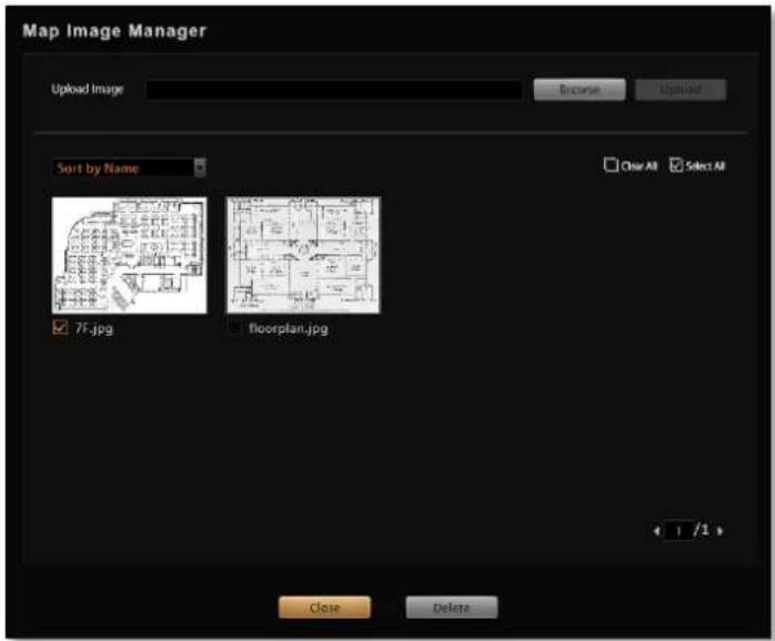
Step 6: Add Devices to the Map
Pull a device from Device List to the map.
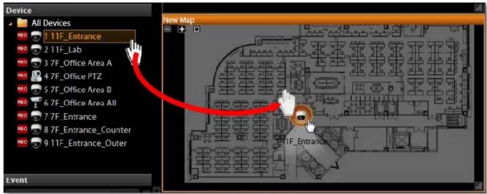
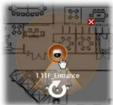
●To remove this device from map:
Click
●To move this device:
Left-click on the device icon and drag.
●To turn the pointed direction:
Mouse over the viewing angle area, left-click on the clockwise arrow to turn the direction.
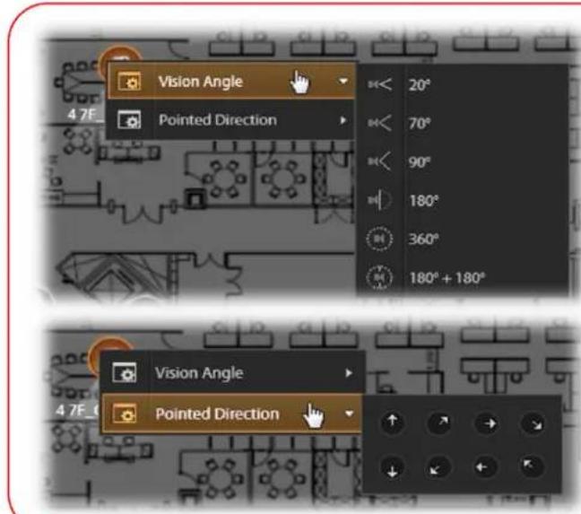
- To adjust precise pointed direction: Right-click on the device icon, select "Pointed Direction".
- To adjust device's viewing angle: Right-click on the device icon, select "Vision Angle".
Step 7: Adjust the Channel Size & Layout
- Adjust the channel size:
Click on right lower corner of the channel window, drag and then release.
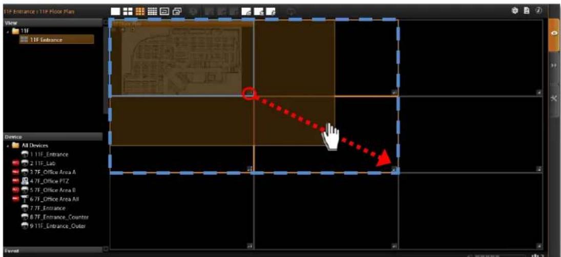
●Switch channel windows:
Click on a channel title until the cross arrow appears, hold it to drag this device or map to your desired channel.
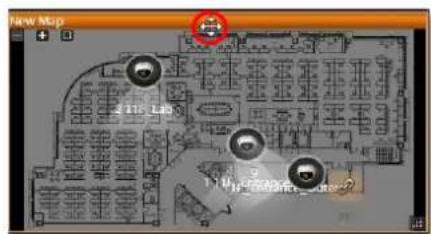
Step 8: Save the View
Click on View Tool Bar to save it.
Step 9: Set Default View
To set a View as default, select it in the View List panel and then click By next time you log in, you will directly enter this View.
on View Tool Bar.
Step 10: Set Default Hotspot Channel (Optional)
By system default, the global hotspot channel will always be the top left one. You can set any other channel on your live view screen to be the default hotspot channel. Right-click on the channel and select "Default Hotspot" Default Hotspot , then click on View Tool Bar to save it.
Step 11: Set Fisheye Camera Mode
Define a view for a fisheye camera channel by selecting its mode and using ePTZ control. Please note that the maximum number of fisheye channels on the same View is 16.
- On this channel, right-click to bring up channel menu, click "Fisheye Mode" and select one mode.
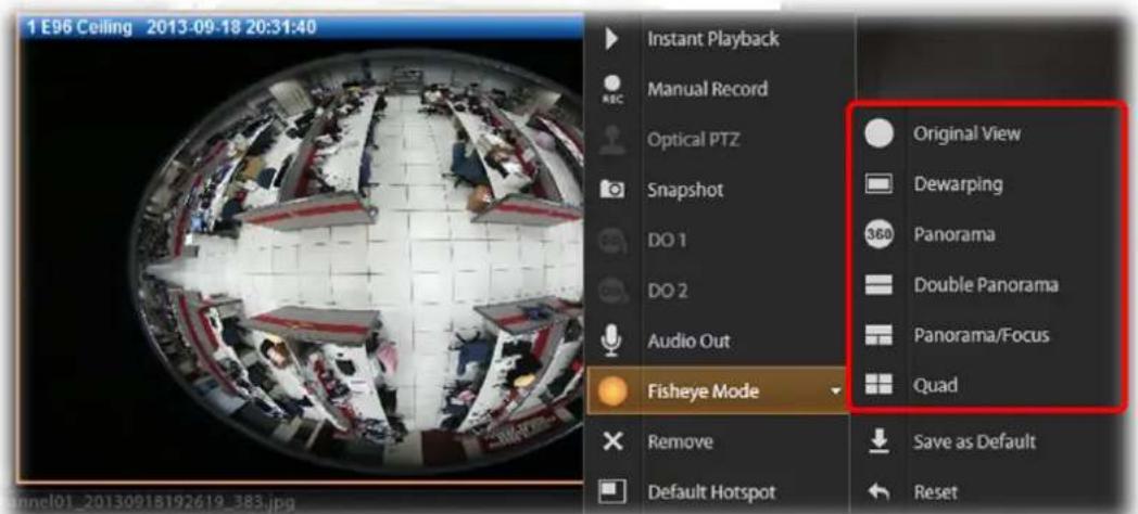
- After the fisheye mode is selected, click the entire channel or a region of interest.
●Use PTZ Panel controls to operate PTZ movements:
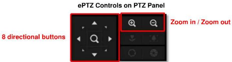
- Click the mouse anywhere on the view to pan/tilt, scroll the mouse wheel to zoom in/out.
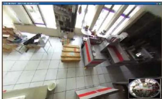
natural_image
Interior view of a cluttered room with tiled floor, furniture, and large windows (no visible text or symbols)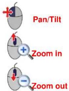
- To reset the ePTZ navigation area back to default viewing angle, right-click to bring up channel menu, and then click "Reset".
- click □ on View Tool Bar to save the configuration.
Note
Once a channel is changed to any of the following fisheye modes: Dewarping, Panorama, Double Panorama, Panorama/Focus or Quad, the resolution of this live stream will become 1920x1080, while NVR still records the live stream at the resolution you set on Setup page.
Manage the Views
Each View belongs to a specific View Group. With the group management, NVR 3.0 Server makes it easy to deal with Views you created for multiple Users.
After you created and saved the Views on Live View screen, click → View Manager.
1 Click on the right arrow icon in front of a group folder to reveal its Views.
2 By selecting a View, you may directly modify its name in Name field.
3 You may change a group's Group Type. Upon the change, for example, by changing a group from "Private" to "Public", all the views belonging to it will be open to every User.
4 Click this icon to add a new group.
5 Click this icon to delete a selected group.
6 Click this icon to copy a selected group to another group.
7 Click this icon to move a selected group to another group.

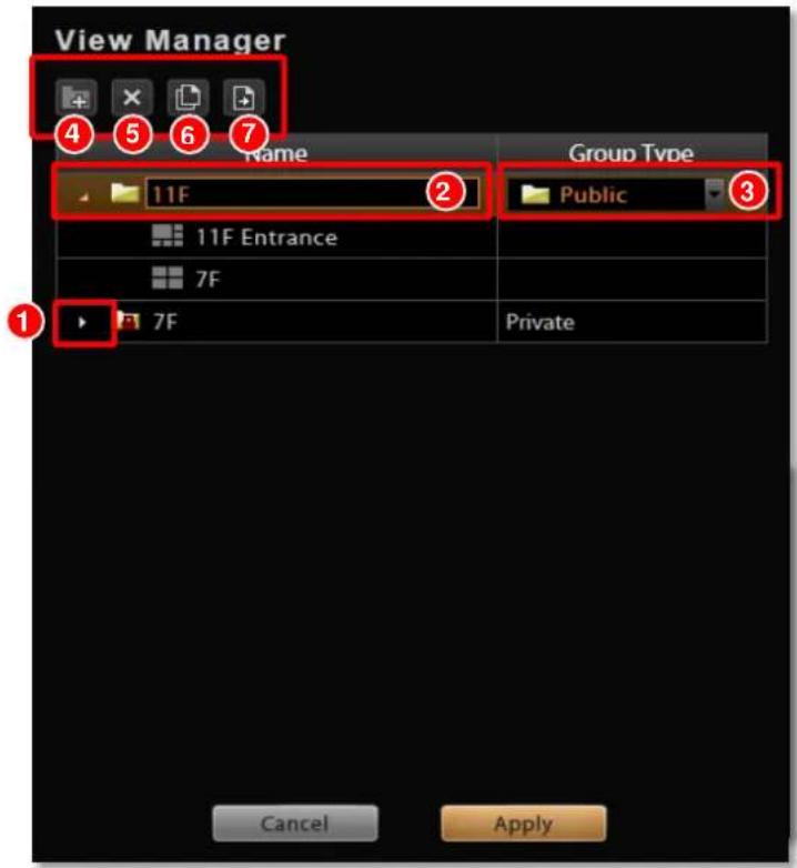
Set View Link
By creating a link button on a map view, you can directly be linked to another specific view by clicking the button. On the picture below shows how to create a link button to 7F View on 11F View.
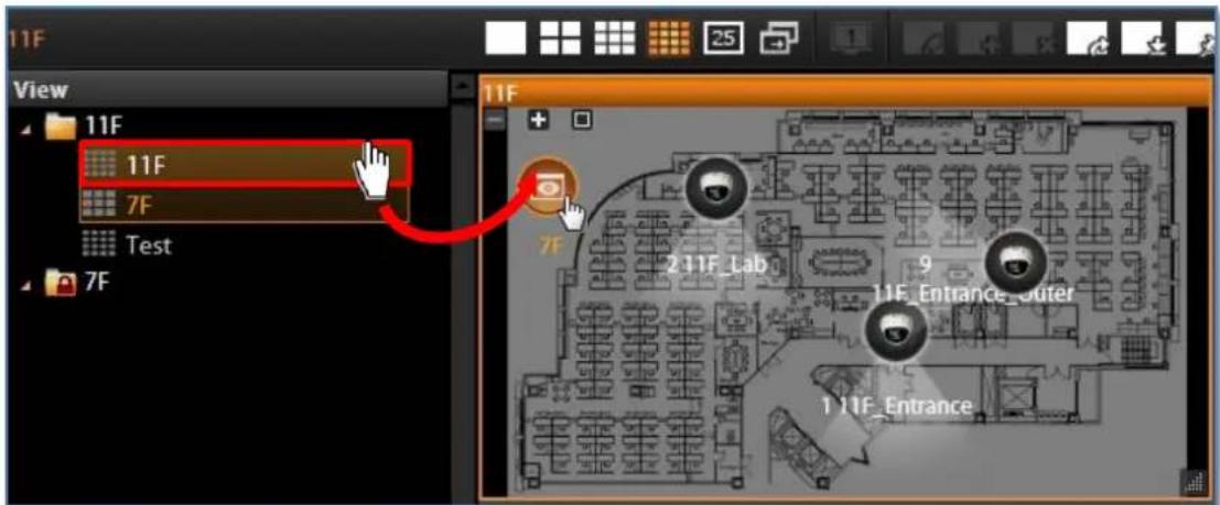
- Select a View, on which you will place a link button to another view.
- Click ☐ on View Toolbar to enter edit mode.
- From View List, drag the target View to current View, a link button will appear.
- Click ☐ on View Toolbar to save it.
Set View Patrol
You may have the saved Views patrol in turns. In this way, the views in different area in your site may cycle through themselves for you automatically.
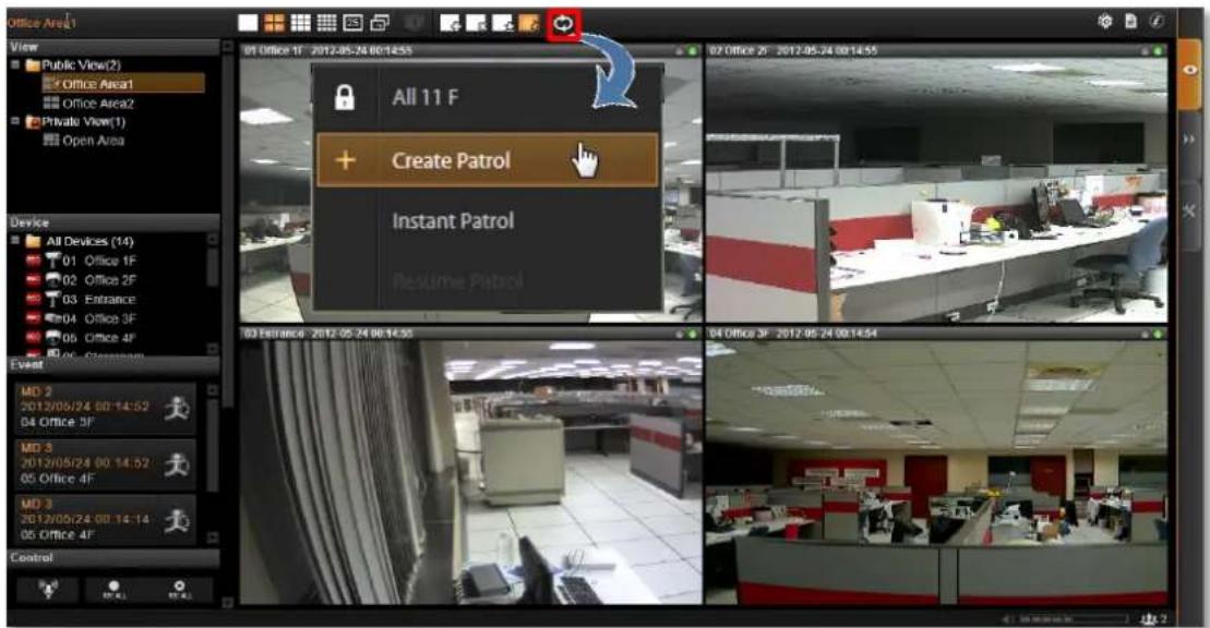
On View Toolbar, click 📊 then select Create Patrol.
- Input the Patrol Name
- Select the Patrol Type to be either available for all Users or to the creator's account only.
- Define the Global Dwell Time between the views. If you want to set different dwell time length for individual Views, do not check this option, and configure them separately in the table below.
- Choose the Views to display in patrol. If you select the All Device group, you will also need to select "All Device Layout Style" for it.
- Click "Apply" to save the settings.
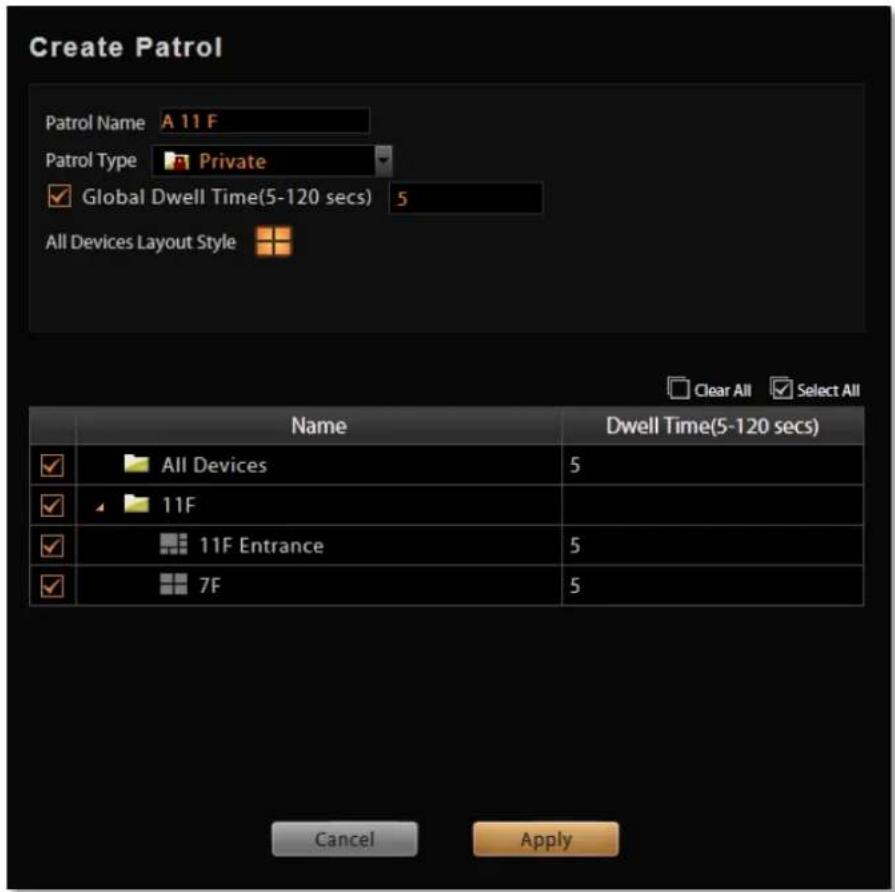
- The saved patrols will be shown on the patrol list after you click 📊 on View Tool Bar, you may delete and edit a saved patrol or select it to start patrolling.
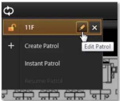
Tips to Enhance Live View Performance
Live view for multiple channels requires sufficient computing power to run the performance. In certain extreme cases, like when viewing several megapixel H.264 video streams at the same time, client computer will be overloaded and hence affect browser's performance. This is a common limitation imposed upon all Windows based video management programs and web browser.
To enhance live view performance, below are several tips you may try:
-
Use dual stream mode for those devices supporting this function. Enable the dual stream mode and use the stream of lower resolution/frame rate/bit rate for live view, and megapixel resolution stream for recording.
-
Use another browser client to share these high-resolution channels. Given that there are 32 megapixel channels to be monitored, you may have Layout 1 to display channel 1\~16, set Layout 2 to display channel 17\~32, then open one browser client to show Layout 1 and the second browser on an extended monitor to show Layout 2.
-
Have NVR automatically lower the frame rate of live streams when system loading is high. Go to Setup page → System tab→ Settings → Display Performance Setting and enable this function. Basically, this setting will lower frame rate when the CPU usage is above certain percentage. You may also enable “Lower the frame rate when current layout is above_”, in this way, when the layout is displaying over certain number of channels, the frame rate of all live streams will be declined. This setting will be applied to the live display of all connected clients except for the client on GNR..
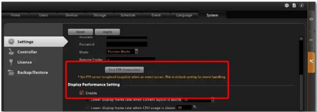
- A Workstation client computer can have its own specific display configuration without being affected by NVR universal setting. Log in as NVR3 Workstation client, go to Setup page → System tab → Workstation and configure the Display Performance Setting.
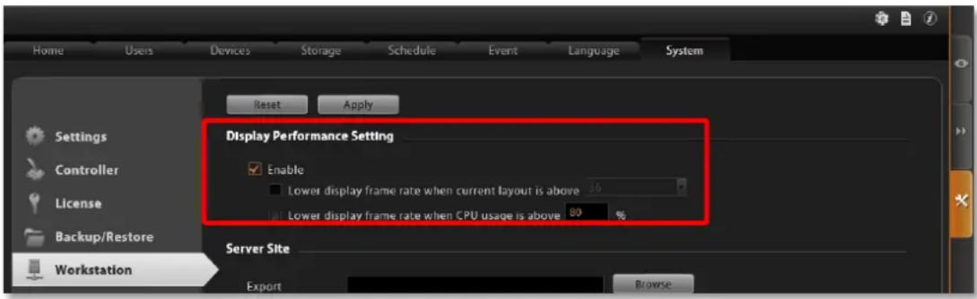
Note
By default, on GNR, when the number of layout on Live View or Playback screen exceeds four, all the channels will automatically turn in to Decode-I mode. For smooth video quality, please remember to go to Setup page → System tab→ Workstation and configure the Display Performance Setting.
Customize System Language
NVR server supports multiple languages for user interface display. There are already 10 translated language files in the server system. Each language is open to customization based on your own needs. This section will describe how to choose or customize language strings for your site.
System Languages List
You may decide which languages to be selectable on Login screen. The chosen languages will appear on the "Language" dropdown list.
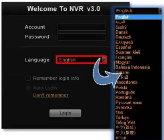
Go to Setup page →Language tab, click "Active Languages". On popup window, check the languages you need, and click "Apply". By default, all languages are selected, as the default system language, English and Traditional Chinese are not removable from this list.
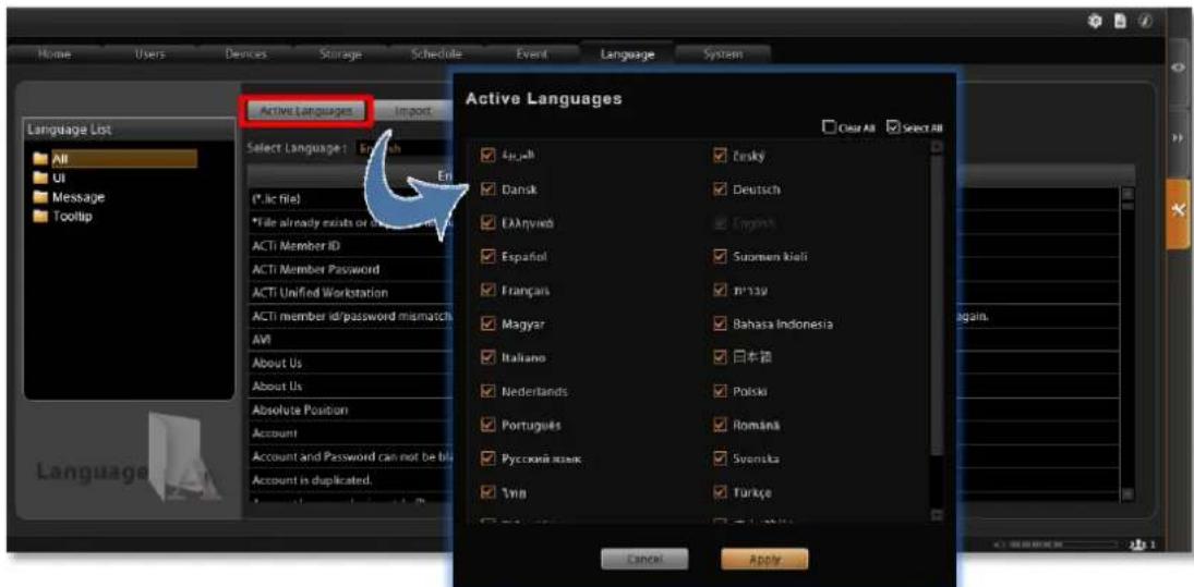
Edit User Interface Wordings
Each language file contains four editable string tables. Each table displays the default wordings in English and the translation in target language.
To view each table:
- Select the language from "Select Language" dropdown list, then select a table from the "Language List" list on the left column.
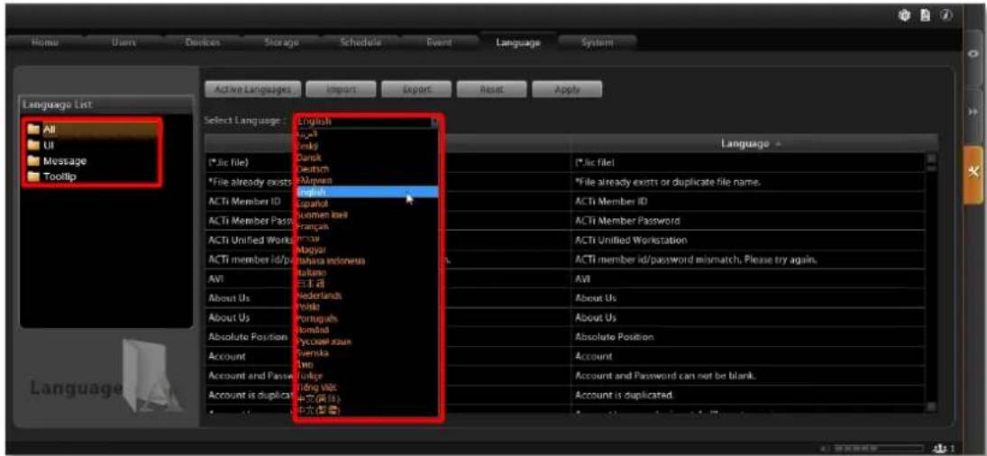
- Your target language will be displayed on the right column, while the default system language "English" appears on the left for reference. Click in any field on right column to customize your desired wordings, and click "Apply" to overwrite the current wordfings.
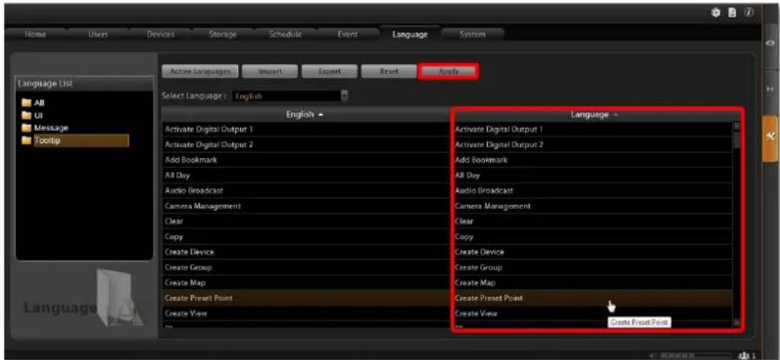
The new string will be applied by next time you log in. If you log in as an NVR3 Workstation client, please press 📋 button on Login page to synchronize with the latest modified language file, then log in to the system.
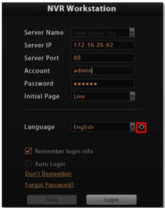
Export / Import Language String File
You may also click "Export" to export the language file as .xml format to edit in Notepad, or "Import" to import a language file to use in the system.
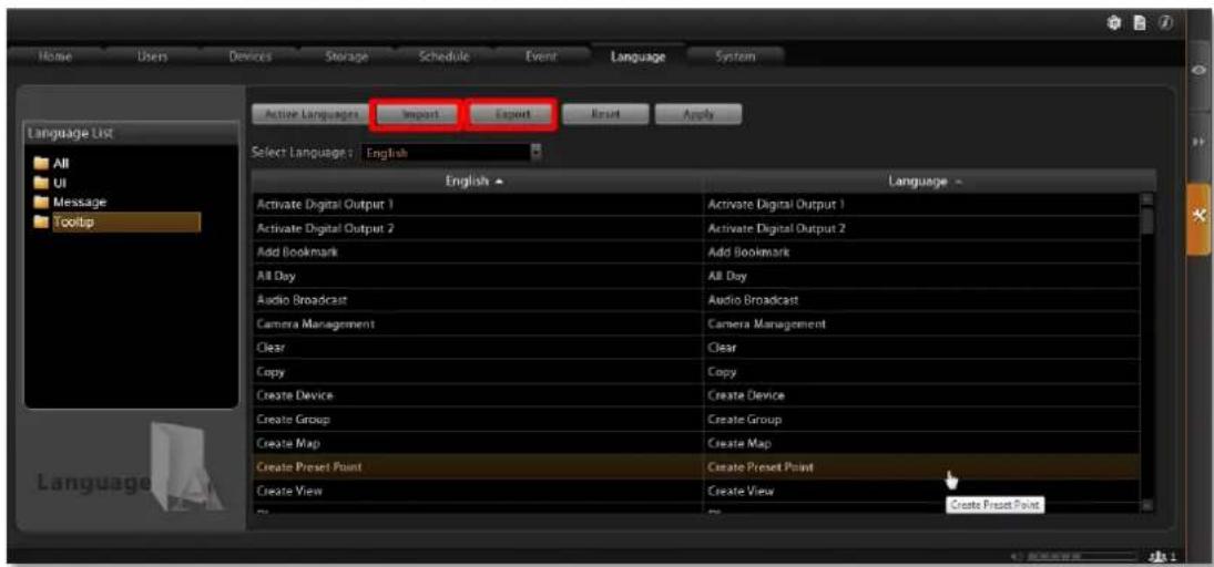
In general, it is suggested that you always save a modified language table with a different file name in a location other than default system language folder C:\Program Files\ACTi Corporation\NVR3\Language, then import it to use. In this way, you can avoid overwriting the original language file.
Display Configurations
You can change the user interface style by arranging the main screen and Panel/Device List on the right or left. Go to Setup page→System tab→Settings, in User Interface Style section, select the setting style then click "Apply". The change will be applied upon your next login.
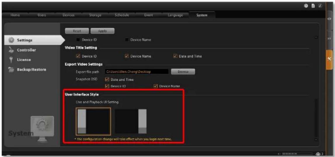
Video & Snapshot Export Configurations
The snapshots taken by Users on Live View and all exported video files are saved to a default file location, and you may configure the destination on NVR server. Go to Setup page→System tab→Settings, in Export Video Settings section, click "Browse" to choose the Export file path.
You may also define what information is printed on each snapshot by checking the items: Date and time, Device ID and Device Name.
These configurations will take place after you click "Apply".
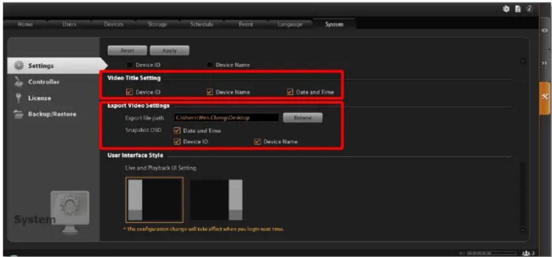
Joystick
On NVR 3.0, other than user interface PTZ panel and mouse operation, you may also control the PTZ movements by physical controllers. NVR 3.0 supports two types of controllers, which both feature in a joystick and twelve buttons for users to assign specific actions.
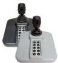
natural_image
Two handheld electronic devices with black and white buttons, no visible text or symbolsModel: IP Desktop Manufacturer: CH Products

Model: Extreme™ 3D Pro
Manufacturer: Logitech
Joystick Configurations
- Log out from NVR server.
- Connect the controller device to your computer. To make sure the device is installed properly, open Windows Start menu and enter Devices and Printers to check the status.
- Log in to NVR server, go to Setup page →System tab, enter "Controller" section and select your product.
- You may assign specific commands from dropdown list to buttons 1\~12 of the controller. When setting is done, click "Apply". The modification you did on one controller model will be applied to the other joystick model as well.
![Home Users Devices Storage Schedules Events Language System Reset Apply CH Products Logitech Settings User Interface Style Controller License Backup/Restore System Zoom Out Zoom In Pan-Top Button 1: Button 2: Button 3: Button 4: Button 5: Button 6: Button 7: Button 8: Button 9: Button 10: Button 11: Button 12: [Page] - Next Page Page: Next Page [PT1] - Obit Preset 1 [PT2] - Obit Preset 2 [PT3] - Obit Preset 3 [PT4] - Obit Preset 4 [PT5] - Obit Preset 5 [PT6] - Obit Preset 6 [PT7] - Obit Preset 7 [PT8] - Obit Preset 8 [PT9] - Obit Preset 9 [PT10] - Obit Preset 10 [PT11] - Obit Preset 11 [PT12] - Obit Preset 12 [PT13] - Obit Preset 13 [PT14] - Obit Preset 14 [PT15] - Obit Preset 15 [PT16] - Obit Preset 16 [PT17] - Obit Preset 17 [PT18] - Obit Preset 18 [PT19] - Obit Preset 19 [PT20] - Obit Preset 20 [PT21] - Obit Preset 21 [PT22] - Obit Preset 22 [PT23] - Obit Preset 23 [PT24] - Obit Preset 24 [PT25] - Obit Preset 25 [PT26] - Obit Preset 26 [PT27] - Obit Preset 27 [PT28] - Obit Preset 28 [PT29] - Obit Preset 29 Controls - Stored0 Using0 Losing0](/content/2026/05/1070493/images/8536acd16815efc53debc4c264232cd5b925fdd424ac809aae40a45e95e1a2ee.jpg)
- To validate its function, go to Live View page and focus on a PTZ device channel to operate the supported PTZ operations.
NVR System Upgrade
When a newer version of the NVR system software for GNR is released on ACTi website, you can download and install it directly to upgrade your NVR system. To download the latest version, please go to http://www.acti.com/product/detail/Standalone_NVR/GNR-3000 to see if there is any newly released version of the NVR system. The upgrade process is as easy as 1-2-3 by following the installation wizard's instructions. The server would start its service right after installation completes, without the need to restart the server computer.
Install the Software
- Execute the install shield application

- Follow the onscreen instructions of Install Shield Wizard, and accept the license agreement and proceed.
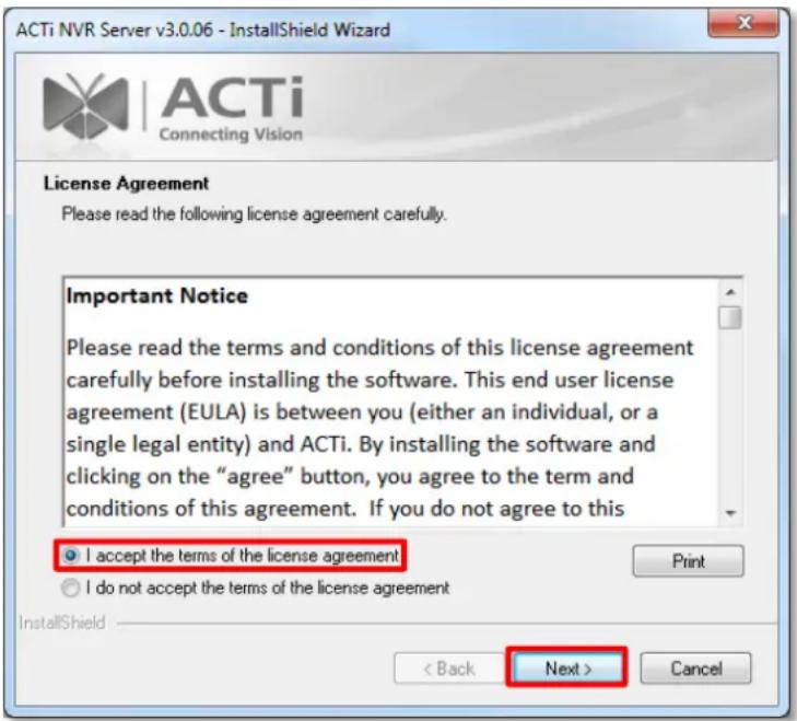
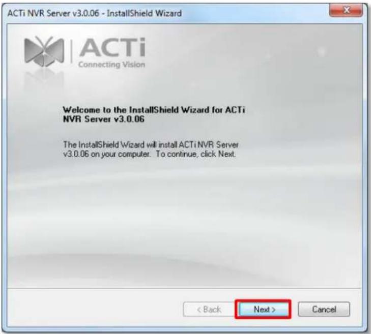
When selecting Setup Type, the default "Complete" will have the program installed on default C drive, you may select "Custom" to choose another program location.
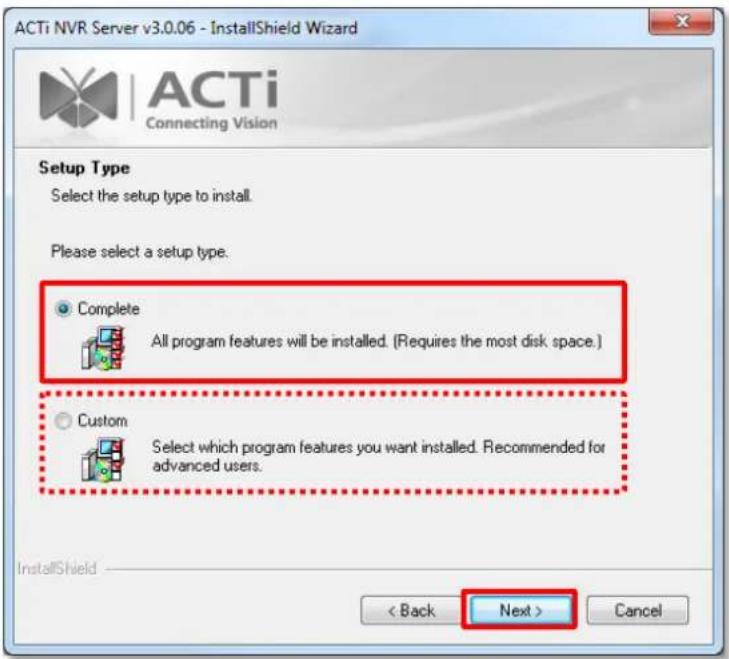
- The IP Port Checker will pop up to confirm the NVR port number with you. The installation program will use 80 as default. You may enter another available port number in "Listen Port" field and click "Apply".
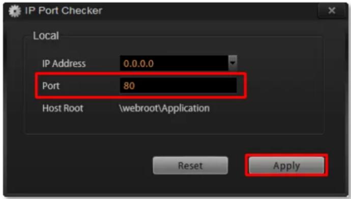
You may just click "Apply" if you are not sure whether this port has been taken or not. If the port is being used by another service, you will be asked to input another available port number.
- As the server port is confirmed, the installation process is done, click "Finish".
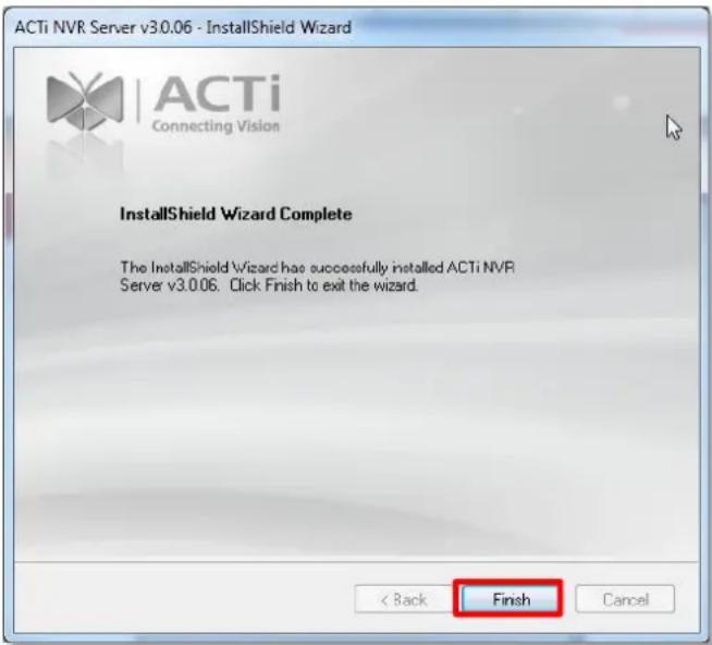
- After the installation completes, connect to http://localhost:port number with Internet Explorer browser, you will see NVR Login page.
Note
If IIS Web Server has been installed on the computer and you are asked to restart the computer during installation process, please
- Choose Yes, I want to restart my computer now. to restart right away.
- After the computer reboots, this install shield will continue to complete the installation.
Workstation Installation and Upgrade
NVR3 Workstation program is wrapped together with the NVR system software in a zip file. When you upgrade the NVR system to a new version, please also upgrade NVR3 Workstation to the same version as the NVR system.
Install or Upgrade the Software
- Execute the install shield application

- Follow the onscreen instructions of Install Shield Wizard, accept the license agreement and proceed.
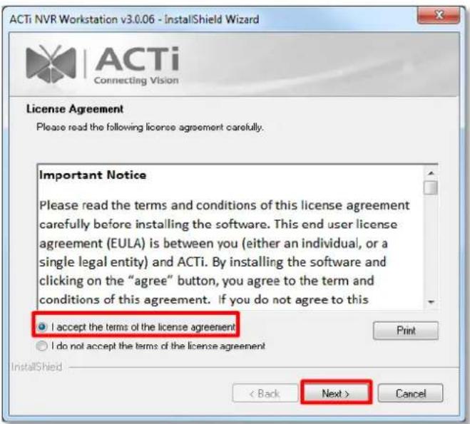
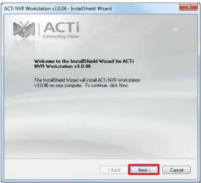
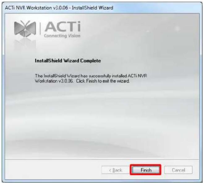
- Double-click the shortcut

on desktop to execute the application.
Back Up System Data
Making regular system backups is always recommended in case of unexpected disasters or accidents that may damage the NVR server. Other than this, you may need to perform an on-demand backing up to migrate the whole NVR server data to another one. There are several types of data on the NVR server essential to your surveillance system, and please consider your purpose and follow the below instructions to create their backups:
Regular Backup (system settings only)
The NVR server can create a backup file of the whole system settings within one click. The backed up settings include the following properties you set for system: (1) Users (2) Device (3) Storage (4) Schedule (5) Event (6) System →Settings / User Interface Style / Joystick, and (7) the saved Views in Live View page.
Complete Backup (system settings + video files)
Besides system settings, some organizations may want to back up the video recording occasionally in case that the recording hard drives may fail. The recording files (*.raw) can only be played on the playback utility Archive Player. You may download it from http://www.acti.com/utility
Step 1: Back up System Settings
- Go to Setup page → System tab → Backup / Restore.
- In Backup section, click "Browse" to select the destination for the backup file, and the file will be saved as Backup_YYYYMMDD.xml file. Then click "Backup" to export the file.
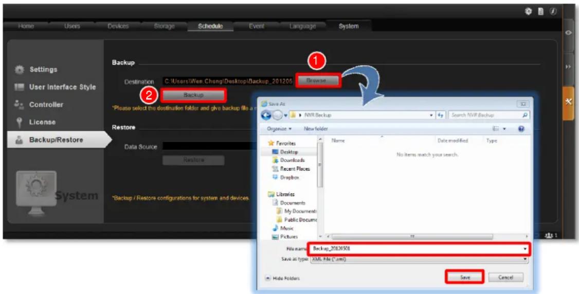
Important Notice
The license data is not included in the system backup file. You have to preserve the license key information provided in email or printed card after the purchase takes place.
Step 2: Back up Recording Files Folder (Optional)
Back up the whole Recordings folder(s) with the recorded video files on storage hard drive(s). If you selected multiple storage hard drives via Setup page → Storage tab → "Disk Drive List", the server may have generated one Recordings folder under each selected drive. If you have renamed the folders or change the locations, please make sure you find the correct path.
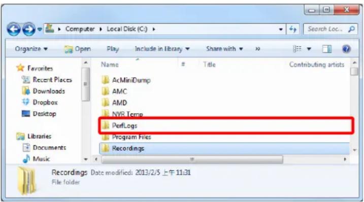
Step 3: Back up Recording Files Index Folder (Optional)
This step is necessary for the NVR 3.0 system migration between two servers. The recording files index folder contains important video index data that the NVR server needs to process recorded video clips. Enter the server program folder ACTi Corporation\NVR3\DataSource, and back up the DataBase folder (where stores the recording files index data).
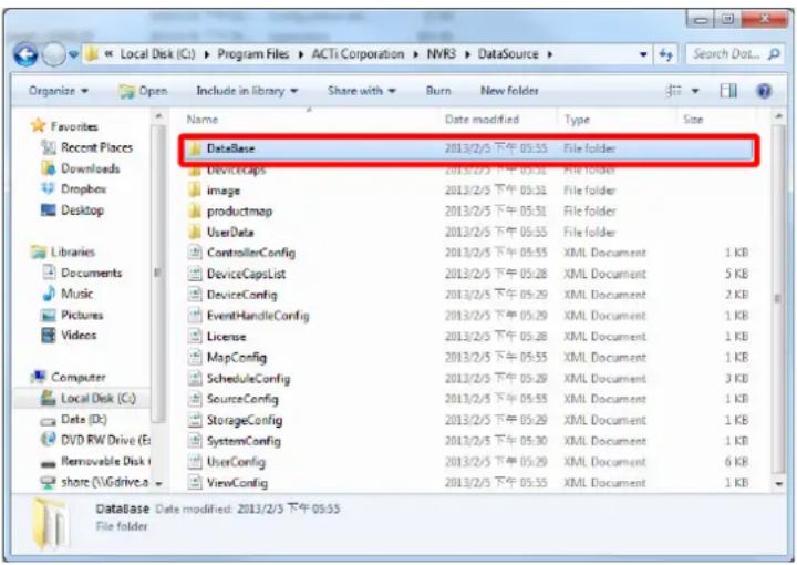
Step 4: System Log (Optional)
The system log records the operations users perform during logging in to the NVR server. You may export the system log of latest three days as *.csv file as backup. Please refer to the section Export the Log on page 108 for instructions.
Restore System Data
Before starting restoring the system, make sure you already have the backup file (.xml). Please follow the below steps to restore the configuration.
- Go to Setup page → System tab → Backup / Restore.
- In Restore section, click "Browse" to select the backup file, and then click "Restore" to start restoring the settings.
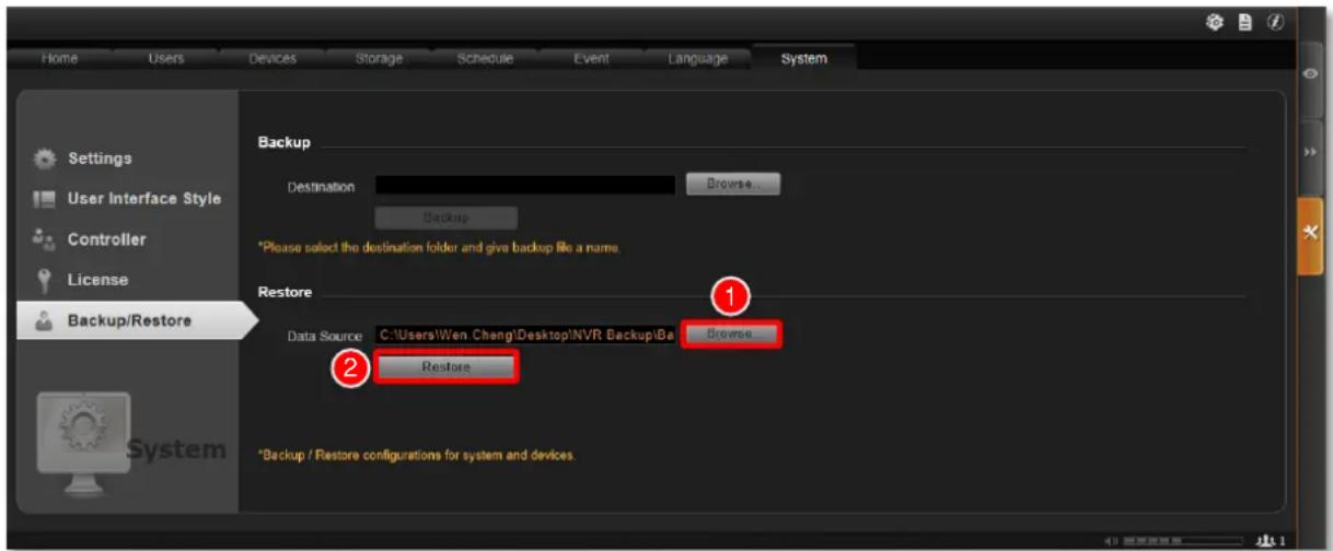
- The restoring process requires logging out of the NVR server. After restoring is done, you may log in using your previous user account properties.
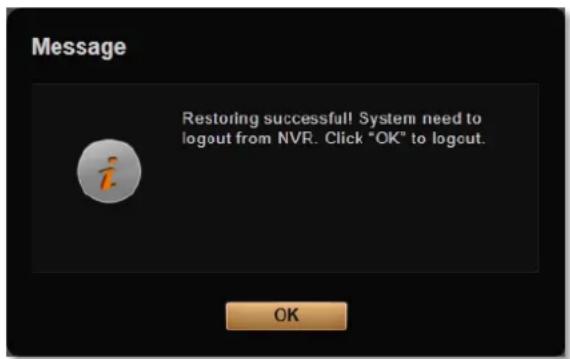
Advanced Administrative Tasks
To assist the NVR administrator in monitoring the server status and basic trouble-shooting, the NVR3 Administrator Tool is installed along with NVR server program on the server computer. This tool will start running as the server computer starts up, and resides in the system tray. You may double-click the icon to open this tool.
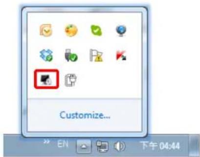
NVR Server Status
You may observe the NVR services status on Service tab.
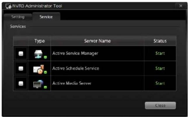
Change Server Port
On Settings tab, input a new port and then click "Apply".
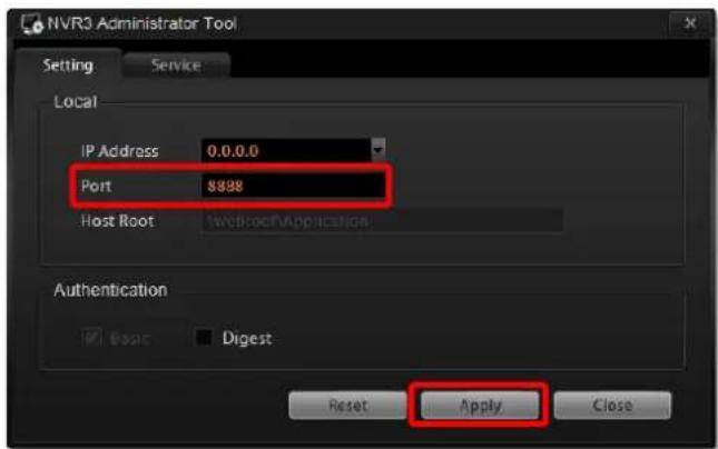
Change Authentication Method
You may enable the Digest authentication other than the basic way. With this method, User's credentials are encrypted using MD5 algorithm. In this way, there is more secure protection to prevent from unauthorized access.
Please also note that, with Digest authentication method enabled, a mobile client user or a domain user will be blocked from NVR system.
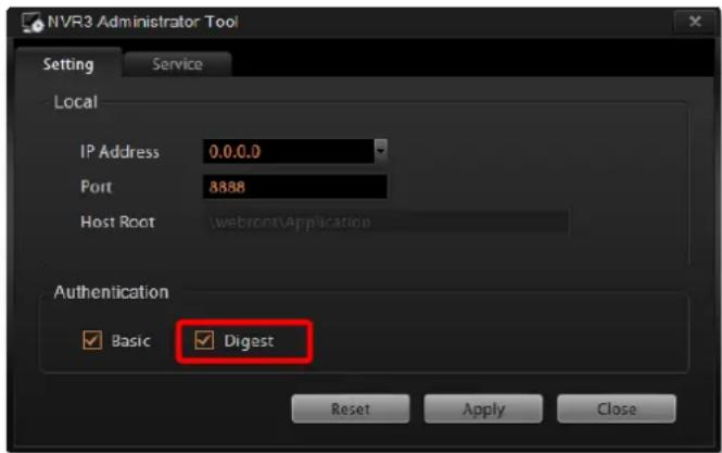
Switch to Redundancy Server
An NVR server can serve as a redundancy server for other NVR server. ACTi's Redundancy Server records all surveillance videos directly from camera devices, logs and performs actions for real-time event notifications on behalf of the NVR server during system downtime.
Authorized users may also access the Redundancy Server when it is in use for live-monitoring or playback options. After the NVR server becomes available, the Redundancy Server will then automatically synchronize all recorded video and events back to the NVR server.
Before you start,
- Prepare a specific computer to be dedicated to carrying out the redundancy tasks.
- Purchase the redundancy server license from ACTi sales representative. One redundancy server computer will require one license, which can serve maximum sixteen (16) NVR servers.
- If your are going to install the redundancy server on a computer, go to http://www.acti.com/DownloadCenter to download and install NVR server program on the computer.
You can also switch your GNR to a redundancy server. However, by applying this change, the original settings and recordings of this server will all be overwritten.
License Registration
With a successful purchase, you will receive a license key for registration
- Enter Administrative Tool interface by clicking the icon on Windows taskbar.
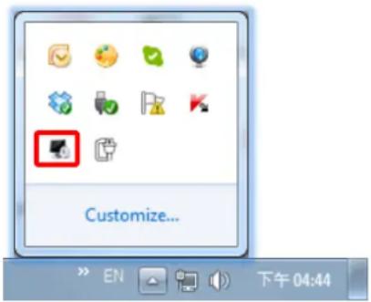
-
On Settings page, select "Redundancy Server". You can switch the server mode back to NVR Server here.
-
The other relevant settings pages will then appear. Enter "License" to start registering. If this server has access to Internet, please select "Online Registration" or you can perform "Offline Registration" by obtaining an activation file from http://www.acti.com/support/LicenseMgt beforehand. Fill in the required fields and click "Register".
If you are trying to switch an NVR server which has been operating for a while to a Redundancy server, please be aware that, by doing so, the original NVR relevant settings and recordings saved previously will ALL be erased.
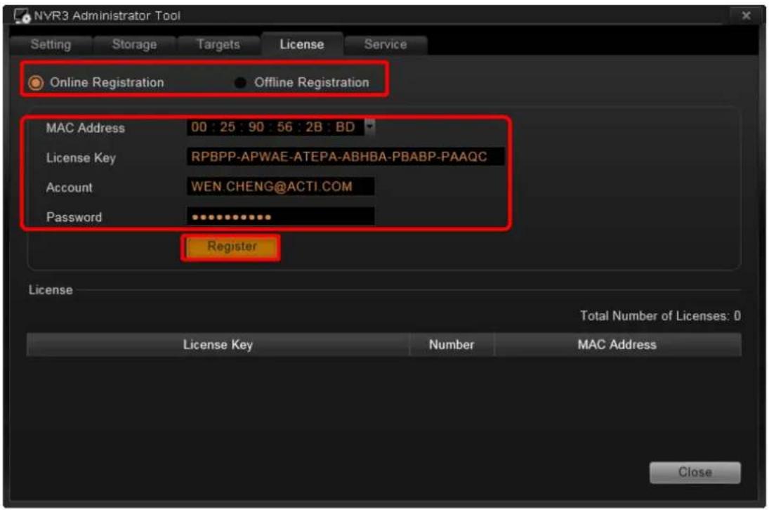
After the registration, the license information will appear on this page.
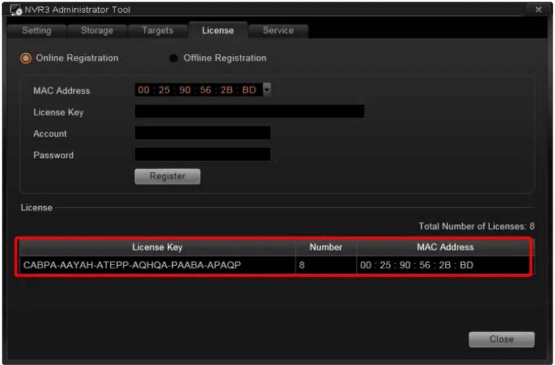
Set up Redundancy Server
- Go to the "Storage" page to set up the storage space configuration
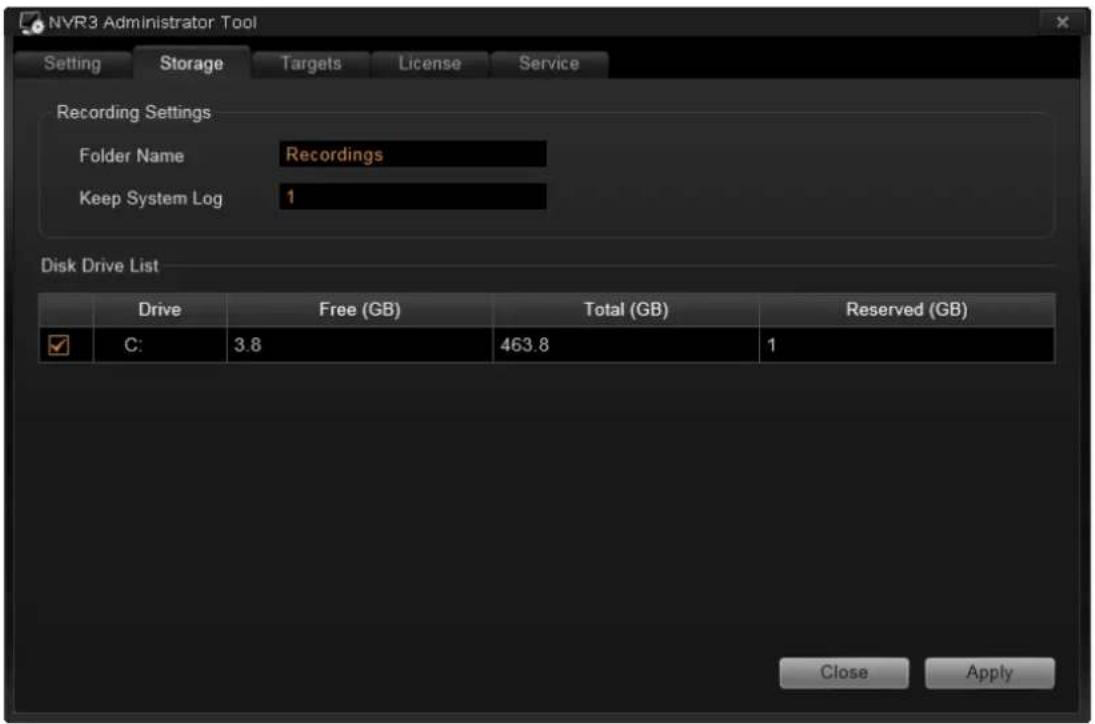
- Go to "Target" page to edit the list of the target NVR servers. Click "Add" and fill in the connection properties of the NVR server and click "Apply".
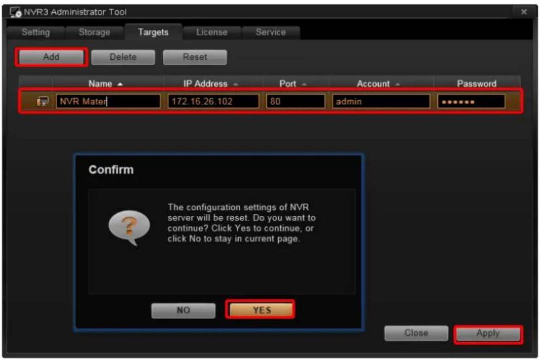
- After you click "Yes" to confirm this configuration, this NVR will immediate turn into an redundancy server on a first-come-first-served basis. By entering "Service" page, you can observe the service status.
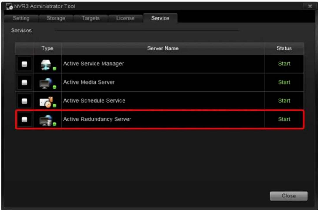
- Content Overview
- Related Documentation
- Technical Support
- System Integration
- Conventions Used in This Manual
- Important Notice
- Note
- Tip
- Legal Notice
- Disclaimer
- Copyright
- Trademarks
- Regulatory Compliance Information
- Federal Communications Commission Statement
- European Community Compliance Statement
- Table of Contents
- About This Manual 2
- Legal Notice 5
- Table of Contents 7
- Overview 13
- Getting Started 17
- Log In to the System 46
- Remote Workstation Client Login 48
- Access the NVR Server via Internet Explorer ....51
- Log in Failure Troubleshooting 51
- Login 55
- Set up the System 56
- Setup Wizard....56
- NVR Main Screen....59
- Add Devices....60
- Manage Multiple Devices....69
- Configure Device Settings....72
- Schedule Recordings 91
- Event Management....98
- System Log 106
- Storage Management 109
- Manage User Groups/ Users 111
- Customize Views 117
- Customize System Language....129
- Display Configurations....132
- Video & Snapshot Export Configurations 133
- Joystick 134
- NVR System Upgrade ....135
- Workstation Installation and Upgrade 139
- Back Up System Data....141
- Overview
- Product Overview
- ●Computer
- ●NVR 3.0 Server System
- ●NVR 3.0 Client Application
- Server / Client Architecture
- Client PC System Requirements
- Getting Started
- What's in the Box
- At a Glance
- Hard Disk Installation
- Step 1: Remove the Tray
- Step 2: Mount the Disk
- Step 3: Install the Tray
- Connect the Devices
- Start the Unit
- Definitions of LED Indicators
- Turn Off the Unit
- Enter Windows
- Adjust Screen Resolution
- Get the Hard Disks Ready for Recording
- Windows Volume Types Comparison
- GNR-3000 System Administrator's Manual
- Start Creating Disk Volumes
- Observe Disk Status
- Live View Screen
- Confirm the schedule-recording setting
- Check Disk Drive List
- Disk Management
- Trouble-shoot the Disk Drives
- Reactivate the Disk
- Check the Physical Connection
- Reactivate the Volume
- Volume Resynchronization
- Repair the Mirrored Volume
- Replace the Disk
- Configure the IP Address
- Find the IP Address of GNR
- Assign a Static IP Address to GNR
- On Connection Status window, click "Properties
- License and Activation
- Please note:
- Online Activation
- Offline Activation
- Step-by-step Activation Process
- Online Activation SOP
- Offline Activation SOP
- Verify Your License
- Important
- How to find MAC Address
- Log In to the System
- Access the NVR Server via NVR3 Workstation
- Local Workstation Client Login
- Enter Account & Password
- Choose the Initial Page
- Language
- Remember Login Information and Auto Login
- Retrieve the User Password
- Remote Workstation Client Login
- Server IP & Server Port
- Enter Account & Password
- Choose the Initial Page
- Language
- Remember Login Information and Auto Login
- Retrieve the User Password
- Server Name/Server Sites List
- Export current server sites list
- Import a server site list
- Access the NVR Server via Internet Explorer
- Accept ActiveX Controls Installation Requests
- Log in Failure Troubleshooting
- Condition 1: Why can't I access NVR server via web browser?
- Cause 1: The NVR server is not ready
- Condition 2: Why can't I install Active X controls after logging in?
- Login
- Change UI language
- Remember Account/Password
- Retrieve the User Password
- Set up the System
- Setup Wizard
- System Settings
- Storage
- Licensing
- The End of Setup Wizard
- NVR Main Screen
- Add Devices
- Search Devices Within Local Area Network
- Search Devices Within Local Area Network with ONVIF
- Add Devices on WAN or Other Local Area Networks
- Device Status
- Add Non-ACTi Cameras
- Manage Multiple Devices
- Modify Basic Connection Settings
- Delete Devices
- Copy Settings Across Devices
- Add Video Streams from a Multi-channel Device
- Saving CPU loading with Your Dual Streaming devices
- Configure Device Settings
- Configure Video Format
- Save Storage by Setting Event Recording Frame Rate
- Schedule Recording
- Event Recording
- Event Recording with Frame Rate Adjustment
- How to Make Use of Event Recording with Frame Rate Adjustment
- Scenario A:
- Scenario B:
- Fine-tune the Image
- Configure Motion Settings
- To move the entire frame
- To disable this detection region
- To adjust the region dimension
- Configure Storage Card Settings
- Configure PTZ Device
- How to Do Live PTZ Operation
- Optical PTZ Navigation
- Digital PTZ Navigation
- Set PTZ Preset Points
- Set PTZ Command
- Set PTZ Preset Tour
- Configure Fisheye Cameras
- Adjust Video Quality Settings
- Adjust Fisheye Display Settings
- Schedule Recordings
- Configure the Recording File Properties
- How to make proper storage arrangement
- Set the Schedule
- Use Time Setting Quick Buttons to Set the Time in One Click
- Lock Specific Days
- Copy an Existing Schedule to Others
- View the Entire Recording Schedule
- How to Know if the Recording is Proceeding?
- Event Management
- How Does NVR Handle Events
- How to Edit an Event Rule
- Setup page →System tab→Settings →E-mail& SMTP Settings.
- Manage the Event Rules
- View the Event Rules
- Delete the Event Rules
- How to Setup SMTP Settings for Event Rules
- How to Setup FTP Settings for Event Rules
- System Log
- Define Search Time
- Choose Log Type
- Read the Log
- Export the Log
- Storage Management
- Change Recordings Folder Name
- Set System Log Lifecycle
- Set Hard Drives for the Recorded Files Deletion Rule
- Manage User Groups/ Users
- Access Permissions
- User Groups
- Add Users
- Account /Password Rules
- Domain Users Management
- Customize Views
- Live View interface overview
- Step 1: Create a New View
- Step 2: Enter Edit Mode
- Step 3: Select a Layout
- Step 5: Add a Map
- ●Map brightness:
- - Map size:
- - Edit map title:
- - Remove the whole map:
- - Manage maps:
- Step 6: Add Devices to the Map
- Step 7: Adjust the Channel Size & Layout
- - Adjust the channel size:
- ●Switch channel windows:
- Step 8: Save the View
- Step 9: Set Default View
- Step 10: Set Default Hotspot Channel (Optional)
- Step 11: Set Fisheye Camera Mode
- Manage the Views
- Set View Link
- Set View Patrol
- Tips to Enhance Live View Performance
- Customize System Language
- System Languages List
- Edit User Interface Wordings
- To view each table:
- Export / Import Language String File
- Display Configurations
- Video & Snapshot Export Configurations
- Joystick
- Joystick Configurations
- NVR System Upgrade
- Install the Software
- Workstation Installation and Upgrade
- Install or Upgrade the Software
- Back Up System Data
- Regular Backup (system settings only)
- Complete Backup (system settings + video files)
- Step 1: Back up System Settings
- Step 2: Back up Recording Files Folder (Optional)
- Step 3: Back up Recording Files Index Folder (Optional)
- Step 4: System Log (Optional)
- Restore System Data
- Advanced Administrative Tasks
- NVR Server Status
- Change Server Port
- Change Authentication Method
- Switch to Redundancy Server
- Before you start,
- License Registration
- Set up Redundancy Server
Brand : ACTi
Model : GNR-3000
Category : Video recorder