
CAA-185-200 - Dash cam CLARION - Free user manual and instructions
Find the device manual for free CAA-185-200 CLARION in PDF.


| Product Type | CCD Camera Power Supply Box |
| Brand | Clarion |
| Model | CAA-185-200 |
| Application | Powers and connects a CCD camera in a vehicle |
| Input Voltage | 12V DC (vehicle battery) |
| Output Voltage | 12V DC for camera |
| Included Cables | 1 red, 1 light green, 1 black, 1 additional red, 1 RCA cable |
| Accessories | Electro taps (2), Velcro strips (2), Tapping screws (2) |
| Mounting Options | Screws or velcro |
| Compliance | FCC Class B |
| Material | Standard electronic components |
| Color | Black (typical) |
| Safety Features | Use grommets or insulation tubes to protect harnesses from sharp edges |
| Installation Precautions | Check for wires or brake pipes before drilling |
| Interference Protection | Tested to comply with FCC limits; if interference occurs, consult dealer or technician |
| Number of Connectors | 5 (4 power signal + 1 RCA video) |
| Warranty | Void if modifications not approved by manufacturer |
| Included Manual | Yes, PDF available online |
| Dimensions | Not provided in manual |
| Weight | Not provided in manual |
Frequently Asked Questions - CAA-185-200 CLARION
User questions about CAA-185-200 CLARION
0 question about this device. Answer the ones you know or ask your own.
Ask a new question about this device
Download the instructions for your Dash cam in PDF format for free! Find your manual CAA-185-200 - CLARION and take your electronic device back in hand. On this page are published all the documents necessary for the use of your device. CAA-185-200 by CLARION.
USER MANUAL CAA-185-200 CLARION
CCD Camera Power Supply Box
CAA-185-200
Installation Instructions
1. Precautions
This equipment has been tested and found to comply with the limits for a Class B digital device, pursuant to Part 15 of the FCC Rules.
These limits are designed to provide reasonable protection against harmful interference in a residential installation. This equipment generates, uses, and can radiate radio frequency energy and, if not installed and used in accordance with the instructions, may cause harmful interference to radio communications. However, there is no guarantee that interference will not occur in a particular installation.
If this equipment does cause harmful interference to radio or television reception, which can be determined by turning the equipment off and on, the user is encouraged to consult the dealer or an experienced radio/TV technician for help.
INFORMATION FOR USERS:
CHANGES OR MODIFICATIONS TO THIS PRODUCT NOT APPROVED BY THE MANUFACTURER WILL VOID THE WARRANTY AND WILL VIOLATE FCC APPROVAL.
2. Package Contents
- CCD camera power supply box: ……1
- Bag of accessories: 1 bag Electro taps: 2 Velcro: 1 Velcro: 1
-
Bag of accessories: 1 bag Tapping screws: 2
-
Bag of accessories: 1 bag
Connector cable (red): 1
Connector cable (light green): 1
Connector cable (black): 1
Connector cable (red): 1
- RCA cable 1
3. Making Connections
3-1. System Connection Example

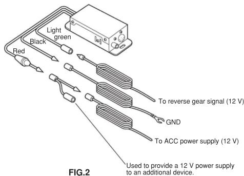
3-2. Connecting the Supplied Cables
Hook up the supplied connector cables as shown in Fig. 2.
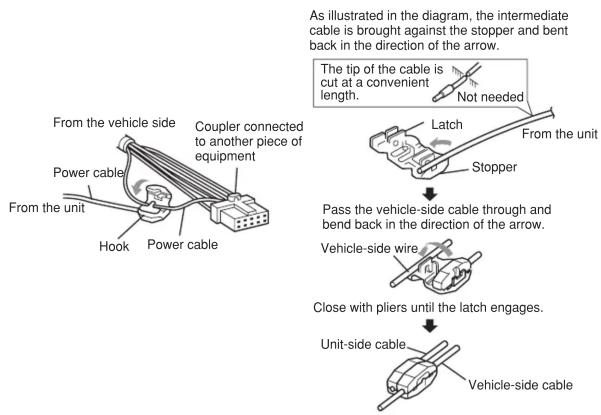
3-3. Power Cable Connections
When connection cannot be made to the terminals, use the supplied Electro Tap to make the connection as illustrated in the diagram.
flowchart
graph TD
    A["From the unit"] --> B["Hook"]
    B --> C["Power cable"]
    C --> D["Coupler connected to another piece of equipment"]
    D --> E["From the vehicle side"]
    E --> F["Tooth"]
    F --> G["Latch"]
    G --> H["Stopper"]
    H --> I["Tooth"]
    I --> J["Tooth"]
    J --> K["Tooth"]
    K --> L["Tooth"]
    L --> M["Tooth"]
    M --> N["Tooth"]
    N --> O["Tooth"]
    O --> P["Tooth"]
    P --> Q["Tooth"]
    Q --> R["Tooth"]
    R --> S["Tooth"]
    S --> T["Tooth"]
    T --> U["Tooth"]
    U --> V["Tooth"]
    V --> W["Tooth"]
    W --> X["Tooth"]
    X --> Y["Tooth"]
    Y --> Z["Tooth"]
    Z --> AA["Tooth"]
    AA --> AB["Tooth"]
    AB --> AC["Tooth"]
    AC --> AD["Tooth"]
    AD --> AE["Tooth"]
    AE --> AF["Tooth"]
    AF --> AG["Tooth"]
    AG --> AH["Tooth"]
    AH --> AI["Tooth"]
    AI --> AJ["Tooth"]
    AJ --> AK["Tooth"]
    AK --> AL["Tooth"]
    AL --> AM["Tooth"]
    AM --> AN["Tooth"]
    AN --> AO["Tooth"]
    AO --> AP["Tooth"]
    AP --> AQ["Tooth"]
    AQ --> AR["Tooth"]
    AR --> AS["Tooth"]
    AS --> AT["Tooth"]
    AT --> AU["Tooth"]
    AU --> AV["Tooth"]
    AV --> AW["Tooth"]
    AW --> AX["Tooth"]
    AX --> AY["Tooth"]
    AY --> AZ["Tooth"]
    AZ --> BA["Tooth"]
    BA --> BB["Tooth"]
    BB --> BC["Tooth"]
    BC --> BD["Tooth"]
    BD --> BE["Tooth"]
    BE --> BF["Tooth"]
    BF --> BG["Tooth"]
    BG --> BH["Tooth"]
    BH --> BI["Tooth"]
    BI --> BJ["Tooth"]
    BJ --> BK["Tooth"]
    BK --> BL["Tooth"]
    BL --> BM["Tooth"]
    BM --> BN["Tooth"]
    BN --> BO["Tooth"]
    BO --> BP["Tooth"]
    BP --> BQ["Tooth"]
    BQ --> BR["Tooth"]
    BR --> BS["Tooth"]
    BS --> BT["Tooth"]
    BT --> BU["Tooth"]
    BU --> BV["Tooth"]
    BV --> BW["Tooth"]
    BW --> BX["Tooth"]
    BX --> BY["Tooth"]
    BY --> BZ["Tooth"]
4. Mounting Procedure
Mounting the CCD Camera Power Supply Box
Mount the CCD camera power supply box in a location such as under a seat using either the supplied tapping screws ( 4 × 12 ) or velcro.


* T thoroughly wipe any dirt from the mounting surface.
* Remove the separator from the back of the velcro and apply it to the mounting surface.
Fig.4Fig.3
CAUTION
- If harnesses will come into contact with the sharp edges of metal plates, or the like, protect them using grommets or insulation tubes.
- Before drilling any holes in a vehicle, make sure that there are no electrical wires, brake fluid pipes, or the like, running behind to surface to be drilled.
Brand : CLARION
Model : CAA-185-200
Category : Dash cam