AVR-981 - Audio Receiver DENON - Free user manual and instructions
Find the device manual for free AVR-981 DENON in PDF.

| Product Type | AV Surround Receiver |
| Brand | Denon |
| Model | AVR-981 |
| Channels | 5.1 |
| Power Output (per channel) | 100 W (8 ohms, 20 Hz - 20 kHz, 0.05% THD) |
| Decoding Formats | Dolby Digital, DTS, Dolby Pro Logic II |
| Audio Inputs | 6 analog, 2 optical, 1 coaxial digital |
| Video Inputs | 3 composite, 2 S-Video, 1 component |
| Speaker Impedance | 4 - 16 ohms |
| Frequency Response | 20 Hz - 20 kHz ±0.5 dB |
| Signal-to-Noise Ratio | 100 dB (IHF-A) |
| Dimensions (W x H x D) | 17.1 x 6.3 x 15 inches (434 x 160 x 381 mm) |
| Weight | 26.5 lbs (12 kg) |
| Power Supply | AC 120 V, 60 Hz (US model), typical 120V/230V depending on region |
| Power Consumption | 400 W (standby: 0.5 W) |
| Remote Control | Included (RC-911) |
| Main Functions | Surround sound decoding, multi-room (Zone 2), AM/FM tuner, bass management, speaker calibration test tones |
| Maintenance & Cleaning | Wipe with a soft, dry cloth; avoid solvents. Ventilation: keep at least 4 inches clearance. |
| Safety | Do not expose to moisture. Use grounded outlet. Disconnect during storms. |
| Spare Parts & Repairability | Service by qualified technician; contact Denon support for parts. |
| General Information | Released early 2000s. Supports 5.1 speaker setup. Includes on-screen display. |
Frequently Asked Questions - AVR-981 DENON
User questions about AVR-981 DENON
0 question about this device. Answer the ones you know or ask your own.
Ask a new question about this device
Download the instructions for your Audio Receiver in PDF format for free! Find your manual AVR-981 - DENON and take your electronic device back in hand. On this page are published all the documents necessary for the use of your device. AVR-981 by DENON.
USER MANUAL AVR-981 DENON
■ We greatly appreciate your purchase of the AVR-2801/981.
To be sure you take maximum advantage of all the features the AVR-2801/981 has to offer, read these instructions carefully and use the set properly. Be sure to keep this manual for future reference should any questions or problems arise.
TO PREVENT FIRE OR SHOCK HAZARD, DO NOT EXPOSE THIS APPLIANCE TO RAIN OR MOISTURE.

CAUTION
RISK OF ELECTRIC SHOCK DO NOT OPEN

CAUTION: TO REDUCE THE RISK OF ELECTRIC SHOCK, DO NOT REMOVE COVER (OR BACK). NO USER-SERVICEABLE PARTS INSIDE. REFER SERVICING TO QUALIFIED SERVICE PERSONNEL.

The lightning flash with arrowhead symbol, within an equilateral triangle, is intended to alert the user to the presence of uninsulated "dangerous voltage" within the product's enclosure that may be of sufficient magnitude to constitute a risk of electric shock to persons.

The exclamation point within an equilateral triangle is intended to alert the user to the presence of important operating and maintenance (servicing) instructions in the literature accompanying the appliance.
• FOR CANADA MODEL ONLY
CAUTION
TO PREVENT ELECTRIC SHOCK, MATCH WIDE BLADE OF PLUG TO WIDE SLOT, FULLY INSERT.
• POUR LES MODELE CANADIEN UNIQUEMENT
ATTENTION
POUR ÉVITER LES CHOCS ÉLECTRIQUES, INTERODUIRE LA LAME LA PLUS LARGE DE LA FICHE DANS LA BORNE CORRESPONDANTE DE LA PRISE ET POUSSER JUSQU' AU FOND.
This device complies with Part 15 of the FCC Rules. Operation is subject to the following two conditions: (1) This device may not cause harmful interference, and (2) this device must accept any interference received, including interference that may cause undesired operation.
This Class B digital apparatus meets all requirements of the Canadian Interference-Causing Equipment Regulations.
Allow for sufficient heat dispersion when installed on a rack.
- Handle the power cord carefully.
Hold the plug when unplugging the cord.
- Keep the set free from moisture, water, and dust.
- Unplug the power cord when not using the set for long periods of time.
* (For sets with ventilation holes)
- Do not obstruct the ventilation holes.
- Do not let foreign objects in the set.
- Do not let insecticides, benzene, and thinner come in contact with the set.
- Never disassemble or modify the set in any way.
- Read Instructions – All the safety and operating instructions should be read before the appliance is operated.
- Retain Instructions – The safety and operating instructions should be retained for future reference.
- Heed Warnings – All warnings on the appliance and in the operating instructions should be adhered to.
- Follow Instructions – All operating and use instructions should be followed.
- Water and Moisture – The appliance should not be used near water – for example, near a bathtub, washbowl, kitchen sink, laundry tub, in a wet basement, or near a swimming pool, and the like.
- Carts and Stands – The appliance should be used only with a cart or stand that is recommended by the manufacturer.
6A. An appliance and cart combination should be moved with care. Quick stops, excessive force, and uneven surfaces may cause the appliance and cart combination to overturn. - Wall or Ceiling Mounting - The appliance should be mounted to a wall or ceiling only as recommended by the manufacturer.
- Ventilation – The appliance should be situated so that its location or position does not interfere with its proper ventilation. For example, the appliance should not be situated on a bed, sofa, rug, or similar surface that may block the ventilation openings; or, placed in a built-in installation, such as a bookcase or cabinet that may impede the flow of air through the ventilation openings.
- Heat – The appliance should be situated away from heat sources such as radiators, heat registers, stoves, or other appliances (including amplifiers) that produce heat.
- Power Sources – The appliance should be connected to a power supply only of the type described in the operating instructions or as marked on the appliance.
-
Grounding or Polarization – Precautions should be taken so that the grounding or polarization means of an appliance is not defeated.
-
Power-Cord Protection – Power-supply cords should be routed so that they are not likely to be walked on or pinched by items placed upon or against them, paying particular attention to cords at plugs, convenience receptacles, and the point where they exit from the appliance.
- Cleaning – The appliance should be cleaned only as recommended by the manufacturer.
- Power Lines – An outdoor antenna should be located away from power lines.
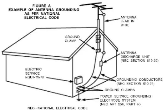
- Outdoor Antenna Grounding – If an outside antenna is connected to the receiver, be sure the antenna system is grounded so as to provide some protection against voltage surges and built-up static charges. Article 810 of the National Electrical Code, ANSI/NFPA 70, provides information with regard to proper grounding of the mast and supporting structure, grounding of the lead-in wire to an antenna-discharge unit, size of grounding conductors, location of antenna-discharge unit, connection to grounding electrodes, and requirements for the grounding electrode. See Figure A.
- Nonuse Periods – The power cord of the appliance should be unplugged from the outlet when left unused for a long period of time.
- Object and Liquid Entry – Care should be taken so that objects do not fall and liquids are not spilled into the enclosure through openings.
- Damage Requiring Service – The appliance should be serviced by qualified service personnel when:
A. The power-supply cord or the plug has been damaged; or
B. Objects have fallen, or liquid has been spilled into the appliance; or
C. The appliance has been exposed to rain; or
D. The appliance does not appear to operate normally or exhibits a marked change in performance; or
E. The appliance has been dropped, or the enclosure damaged.
- Servicing – The user should not attempt to service the appliance beyond that described in the operating instructions. All other servicing should be referred to qualified service personnel.
text_image
FIGURE A EXAMPLE OF ANTENNA GROUNDING AS PER NATIONAL ELECTRICAL CODE GROUNDS CLAMP ELECTRIC SERVICE EQUIPMENT ANTENNA LEAD IN WIRE ANTENNA DISCHARGE UNIT (NEC SECTION 610.20) GROUND CONDUCTORS (NEC SECTION 810.21) GROUND CLAMPS POWER SERVICE GROUNDING ELECTRODE SYSTEM (NEC ART 250, PART H) NEC - NATIONAL ELECTRICAL CODEINTRODUCTION
Thank you for choosing the DENON AVR-2801/981 Digital Surround A / V receiver. This remarkable component has been engineered to provide superb surround sound listening with AV theater sources such as DVD, as well as providing outstanding high fidelity reproduction of your favorite music sources.
As this product is provided with an immense array of features, we recommend that before you begin hookup and operation that you review the contents of this manual before proceeding.
TABLE OF CONTENTS
1 Before Using 4
2 Cautions on Installation 4
3 Cautions on Handling 5
4 Features 5
5 Connections 6-11
6 Part Names and Functions 12, 13
7 Setting up the system 14\~22
8 Remote Control Unit....23\~31
9 Operation 31\~35
10 Surround 36-39
11 DSP Surround Simulation....40-44
12 Listening to the Radio 45-47
13 Last Function Memory 47
14 Initialization of the Microprocessor 47
15 Troubleshooting....48
16 Additional Information 49\~52
17 Specifications 53
ACCESSORIES
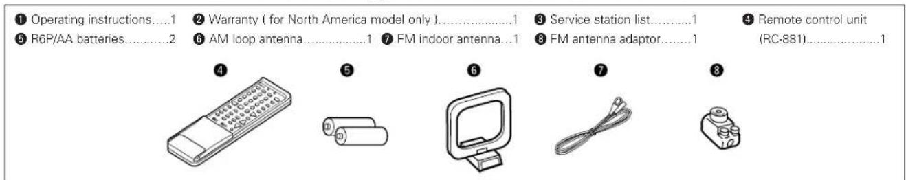
Check that the following parts are included in addition to the main unit:
text_image
① Operating instructions....1 ② Warranty ( for North America model only )....1 ③ Service station list....1 ④ Remote control unit ⑤ R6P/AA batteries....2 ⑥ AM loop antenna....1 ⑦ FM indoor antenna...1 ⑧ FM antenna adaptor....1 (RC-881)....11 BEFORE USING
Pay attention to the following before using this unit:
- Moving the set To prevent short circuits or damaged wires in the connection cords, always unplug the power cord and disconnect the connection cords between all other audio components when moving the set.
- Before turning the power switch on Check once again that all connections are proper and that there are not problems with the connection cords. Always set the power switch to the standby position before connecting and disconnecting connection cords.
2 CAUTIONS ON INSTALLATION
Noise or disturbance of the picture may be generated if this unit or any other electronic equipment using microprocessors is used near a tuner or TV.
If this happens, take the following steps:
• Install this unit as far as possible from the tuner or TV.
- Set the antenna wires from the tuner or TV away from this unit's power cord and input/output connection cords.
- Noise or disturbance tends to occur particularly when using indoor antennas or 300 Ω/ohms feeder wires. We recommend using outdoor antennas and 75 Ω/ohms coaxial cables.
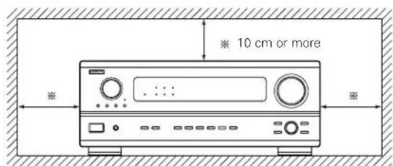
For heat dispersal, leave at least 10 cm of space between the top, back and sides of this unit and the wall or other components.
- Store this instructions in a safe place.
After reading, store this instructions along with the warranty in a safe place. - Note that the illustrations in this instructions may differ from the actual set for explanation purposes.
text_image
10 cm or more Wall3 CAUTIONS ON HANDLING
- Switching the input function when input jacks are not connected
A clicking noise may be produced if the input function is switched when nothing is connected to the input jacks. If this happens, either turn down the MASTER VOLUME control or connect components to the input jacks.
- Muting of PRE OUT jacks, HEADPHONE jack and SPEAKER terminals
The PRE OUT jacks, HEADPHONE jacks and SPEAKER terminals include a muting circuit. Because of this, the output signals are greatly reduced for several seconds after the power switch is turned on or input function, surround mode or any other-set-up is changed. If the volume is turned up during this time, the output will be very high after the muting circuit stops functioning. Always wait until the muting circuit turns off before adjusting the volume.
4 FEATURES
- Dolby Digital
Using advanced digital processing algorithms, Dolby Digital provides up to 5.1 channels of wide-range, high fidelity surround sound. Dolby Digital is the default digital audio delivery system for North American DVD and DTV.
- DTS (Digital Theater Systems)
DTS provides up to 5.1 channels of wide-range, high fidelity surround sound, from sources such as laser disc, DVD and specially-encoded music discs.
- Whenever the power switch is in the STANDBY state, the apparatus is still connected on AC line voltage.
Please be sure to unplug the cord when you leave home for, say, a vacation.
- 24 bit D/A Conversion
All six channels, including the five main channels and the low frequency effects (LFE) channel benefit from reference, for optimum high fidelity reproduction of music and movie soundtracks.
- Video Select Function
Allow you to watch one source (visual) while listening to another source (audio).
5 CONNECTIONS
- Do not plug in the AC cord until all connections have been completed.
- Be sure to connect the left and right channels properly (left with left, right with right).
- Insert the plugs securely. Incomplete connections will result in the generation of noise.
- Use the AC OUTLETS for audio equipment only. Do not use them for hair driers, etc.
- Note that binding pin plug cords together with AC cords or placing them near a power transformer will result in generating hum or other noise.
- Noise or humming may be generated if a connected audio equipment is used independently without turning the power of this unit on. If this happens, turn on the power of the this unit.
Connecting the audio components
- When making connections, also refer to the operating instructions of the other components. The power to these outlets is turned on and off when the power is switched between on and standby from the remote control unit or power switch.
text_image
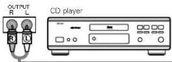
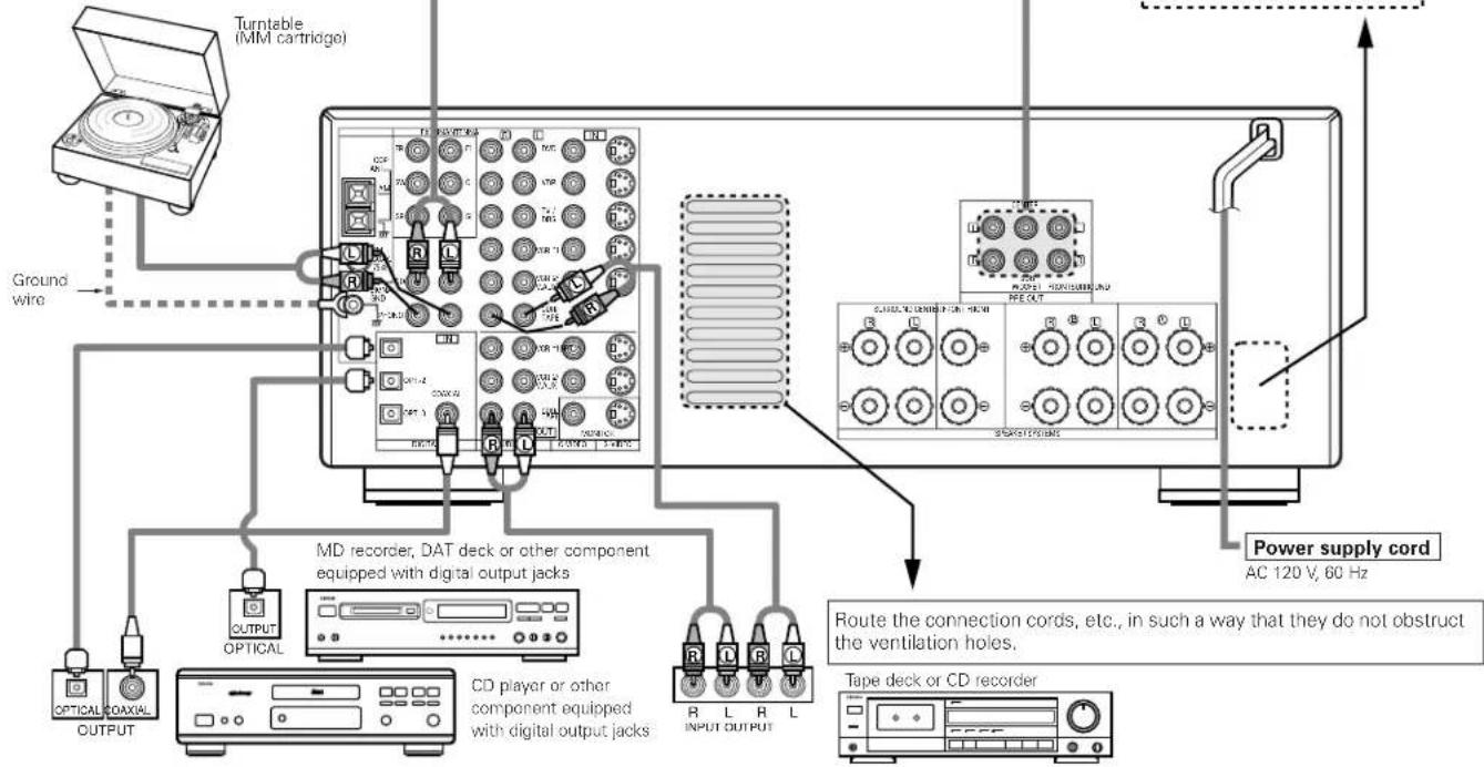
OUTPUT R L CD playerConnecting a CD player
Connect the CD player's analog output jacks (ANALOG OUTPUT) to this unit's CD jacks using pin plug cords.
Connecting a turntable
Connect the turntable's output cord to the AVR-2801/981's PHONO jacks, the L (left) plug to the L jack, the R (right) plug to the right jack.
NOTE:
This unit cannot be used with MC cartridges directly. Use a separate head amplifier or step-up transformer.
If humming or other noise is generated when the ground wire is connected, disconnect the ground wire.
flowchart
graph TD
    A["Turntable (MM cartridge)"] --> B["Ground wire"]
    B --> C["MD recorder, DAT deck or other component equipped with digital output jacks"]
    C --> D["OUTPUT OPTICAL"]
    C --> E["CD player or other component equipped with digital output jacks"]
    D --> F["Tape deck or CD recorder"]
    E --> G["Power supply cord AC 120 V, 60 Hz"]
    F --> H["Route the connection cords, etc., in such a way that they do not obstruct the ventilation holes."]
    G --> I["INPUT OUTPUT"]
    style A fill:#f9f,stroke:#333
    style B fill:#ccf,stroke:#333
    style C fill:#cfc,stroke:#333
    style D fill:#fcc,stroke:#333
    style E fill:#cff,stroke:#333
    style F fill:#ffc,stroke:#333
    style G fill:#cfc,stroke:#333
    style H fill:#fcc,stroke:#333
    style I fill:#ffc,stroke:#333
Connecting the DIGITAL jacks
Use these for connections to audio equipment with digital output. Refer to page 20, 21 for instructions on setting this terminal.
NOTES:
- Use 75 Ω/ohms cable pin cords for coaxial connections.
- Use optical cables for optical connections, removing the cap before connecting.
AC OUTLETS
- SWITCHED
(total capacity - 120 W (1 A.))
The power to these outlets is turned on and off in conjunction with the POWER operation switch on the main unit, and when the power is switched between on and standby from the remote control unit. No power is supplied from these outlets when this unit's power is at standby. Never connect equipment whose total capacity is above 120 W (1 A.).
NOTE:
Only use the AC OUTLETS for audio equipment. Never use them for hair driers, TVs or other electrical appliances.
Route the connection cords, etc., in such a way that they do not obstruct the ventilation holes.
Tape deck or CD recorder
Connecting a tape deck
Connections for recording:
Connect the tape deck's recording input jacks (LINE IN or REC) to this unit's tape recording (CDR/TAPE OUT) jacks using pin plug cords.
Connections for playback:
Connect the tape deck's playback output jacks (LINE OUT or PB) to this unit's tape playback (CDR/TAPE IN) jacks using pin plug cords.
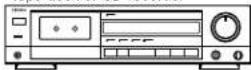
Connecting video components
- To connect the video signal, connect using a 75 Ω/ohms video signal cable cord. Using an improper cable can result in a drop in video quality.
- When making connections, also refer to the operating instructions of the other components.
flowchart
graph TD
    A["TV or DBS tuner"] --> B["TV/DBS"]
    B --> C["Connecting a TV/DBS tuner"]
    C --> D["Connecting a DVD player or a video disc player (VDP)"]
    D --> E["VDP"]
    E --> F["Connect the video disc player's video output jack (VIDEO OUTPUT) to the VIDEO (yellow) VDP/DVD IN jack using a 75 Ω/ohms video coaxial pin plug cord."]
    E --> G["Connect the video disc player's analog audio output jacks (ANALOG AUDIO OUTPUT) to the AUDIO VDP/DVD IN jacks using pin plug cords."]
    E --> H["A DVD player can be connected to the DVD jacks in the same way."]
    E --> I["It is also possible to connect a video disc player, DVD player, video camcorder, game machine, etc., to the VCR-2/V.AUX jacks."]
    J["Monitor TV"] --> K["MONITOR OUT"]
    K --> L["Connect the TV's video input jack (VIDEO INPUT) to the MONITOR OUT jack using a 75 Ω/ohms video coaxial pin plug cord. (See pages 21)."]
    K --> M["Note on connecting the digital input jacks"]
    M --> N["Only audio signals are input to the digital input jacks. For details, see page 6."]
Connecting a video decks
• There are two sets of video deck (VCR) jacks, so two video decks can be connected for simultaneous recording or video copying.
Video input/output connections:
- Connect the video deck's video output jack (VIDEO OUT) to the [VIDEO] (yellow) VCR-1 IN jack, and the video deck's video input jack (VIDEO IN) to the [VIDEO] (yellow) VCR-1 OUT jack using 75 Ω/ohms video coaxial pin plug cords.
Connecting the audio output jacks
- Connect the video deck's audio output jacks (AUDIO OUT) to the [AUDIO] VCR-1 IN jacks, and the video deck's audio input jacks (AUDIO IN) to the [AUDIO] VCR-1 OUT jacks using pin plug cords.
* Connect the second video deck to the VCR-2/V.AUX jacks in the same way.
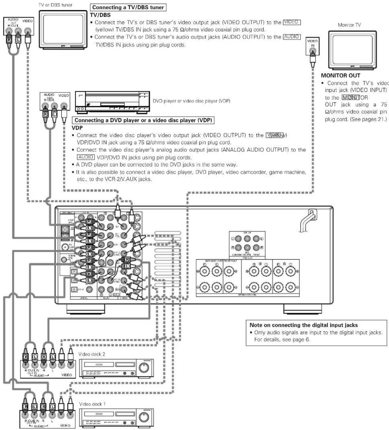
Connecting a video component equipped with S-Video jacks
- When making connections, also refer to the operating instructions of the other components.
• A note on the S input jacks
The input selectors for the S inputs and pin jack inputs work in conjunction with each other.
• Precaution when using S-jacks
This unit's S-jacks (input and output) and video pin jacks (input and output) have independent circuit structures, so that video signals input from the S-jacks are only output from the S-jack outputs and video signals input from the pin jacks are only output from the pin jack outputs.
When connecting this unit with equipment that is equipped with S-jacks, keep the above point in mind and make connections according to the equipment's instruction manuals.
flowchart
graph TD
    A["Connecting a DVD player or a video disc player (VDP)"] --> B["VDP"]
    B --> C["Connecting a monitor TV"]
    C --> D["MONITOR OUT"]
    D --> E["Connecting a TV/DBS tuner"]
    E --> F["Video deck 1"]
    F --> G["Connecting the video decks"]
    G --> H["Video deck 2"]
    H --> I["Connecting the video deck's S output jack (S-OUT) to the S-VIDEO VCR-1 IN jack and the video deck's S input jack (S-IN) to the S-VIDEO VCR-2/V.AUX IN jack and the video deck's S input jack (S-IN) to the VCR-2/A AUX OUT jack using S jack connection cords."]
    style A fill:#f9f,stroke:#333
    style B fill:#ccf,stroke:#333
    style C fill:#cfc,stroke:#333
    style D fill:#fcc,stroke:#333
    style E fill:#cff,stroke:#333
    style F fill:#ffc,stroke:#333
    style G fill:#cfc,stroke:#333
    style H fill:#fcc,stroke:#333
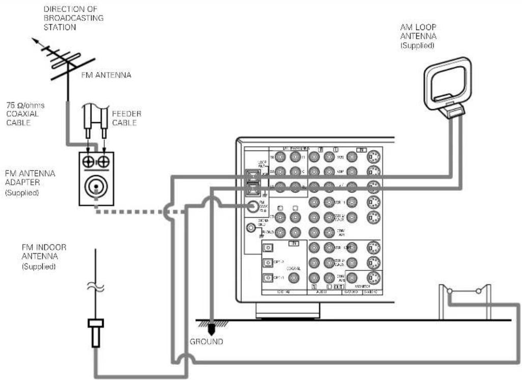
Connecting the antenna terminals
text_image
DIRECTION OF BROADCASTING STATION FM ANTENNA 75 Ω/ohms COAXIAL CABLE FEEDER CABLE FM ANTENNA ADAPTER (Supplied) FM INDOOR ANTENNA (Supplied) AM LOOP ANTENNA (Supplied) GROUND- An F-type FM antenna cable plug can be connected directly.
- If the FM antenna cable's plug is not of the F-type, connect using the included antenna adapter.
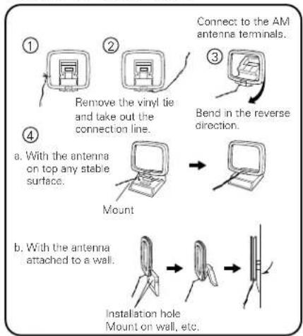
AM loop antenna assembly
flowchart
graph TD
    A["① Remove the vinyl tie and take out the connection line."] --> B["② Connect to the AM antenna terminals."]
    B --> C["③ Bend in the reverse direction."]
    C --> D["④ Mount with antenna attached to a wall."]
    D --> E["⑤ Installation hole Mount on wall, etc."]
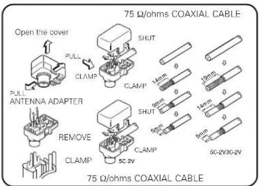
FM antenna adapter assembly
text_image
Open the cover PULL CLAMP PULL ANTENNA ADAPTER REMOVE CLAMP 75 Ω/ohms COAXIAL CABLE SHUT CLAMP 14mm 9mm 9mm 5cm 5cm-2V30-2V 19mm 14mm 5mm 75 Ω/ohms COAXIAL CABLEConnection of AM antennas
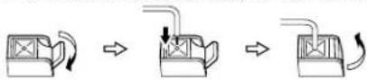
1. Push the lever. 2. Insert the conductor. 3. Return the lever.
Note to CATV system installer:
This reminder is provided to call the CATV system installer's attention to Article 820-40 of the NEC which provides guidelines for proper grounding and, in particular, specifies that the cable ground shall be connected to the grounding system of the building, as close to the point of cable entry as practical.
Notes:
- Do not connect two FM antennas simultaneously.
- Even if an external AM antenna is used, do not disconnect the AM loop antenna.
- Make sure AM loop antenna lead terminals do not touch metal parts of the panel.
Connecting the external input (EXT. IN) jacks
- These input jacks are for inputting multi-channel audio signals in high definition MUSE 3-1 format, multi-channel audio signals from an MPEG multi-channel decoder, or future multi-channel sound format, etc.
- When making connections, also refer to the operating instructions of the other components.
When connecting a high definition (MUSE 3-1 format) component, use a separately sold mono/stereo cable if the surround channel output is monaural.
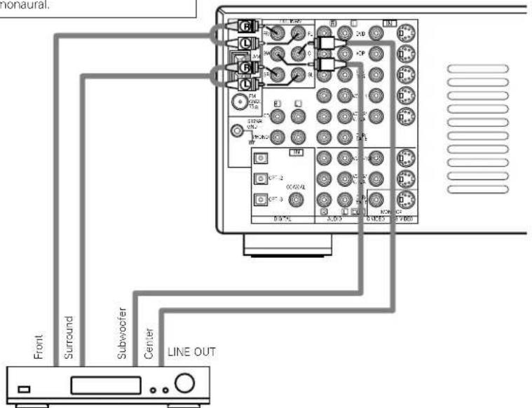
text_image
Monaural. Front Surround Subwoofer Center LINE OUTDecoders with 6-channel analog outputs, etc.
Speaker system connections
- Connect the speaker terminals with the speakers making sure that like polarities are matched ( with , with ). Mismatching of polarities will result in weak central sound, unclear orientation of the various instruments, and the sense of direction of the stereo being impaired.
- When making connections, take care that none of the individual conductors of the speaker cord come in contact with adjacent terminals, with other speaker cord conductors, or with the rear panel.
NOTE: NEVER touch the speaker terminals when the power is on. Doing so could result in electric shocks.
Speaker Impedance
- Speakers with an impedance of from 6 to 16 /ohms can be connected for use as surround and center speakers.
- Speakers with an impedance of 6 to 16/ ohms can be connected for use as front speakers.
- Be careful when using two pairs of front speakers (A + B) at the same time, since use of speakers with an impedance of less than 8 Ω/ohms will lead to damage.
- The protector circuit may be activated if the set is played for long periods of time at high volumes when speakers with an impedance lower than the specified impedance are connected.
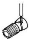
Connection the speaker terminals
-
Loosen by turning counterclockwise
-
Insert the cord. 3. Tighten by turning
clockwise.


Connecting banana plugs
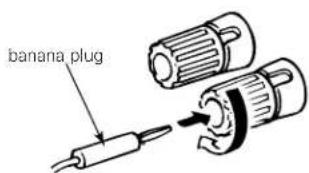
text_image
banana plugTurn clockwise to tighten, then insert the banana plug.
Connections
- When making connections, also refer to the operating instructions of the other components.
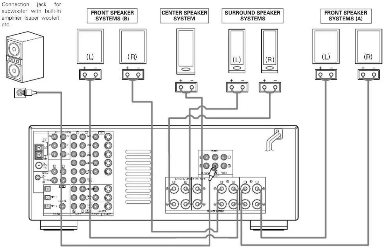
flowchart
graph TD
    A["Connection jack for subwoofer with built-in amplifier (super woofer), etc."] --> B["Front Speaker Systems (B)"]
    A --> C["Center Speaker System"]
    A --> D["Surround Speaker Systems"]
    A --> E["Front Speaker Systems (A)"]
• Precautions when connecting speakers
If a speaker is placed near a TV or video monitor, the colors on the screen may be disturbed by the speaker's magnetism. If this should happen, move the speaker away to a position where it does not have this effect.
Protector circuit
- This unit is equipped with a high-speed protection circuit. The purpose of this circuit is to protect the speakers under circumstances such as when the output of the power amplifier is inadvertently short-circuited and a large current flows, when the temperature surrounding the unit becomes unusually high, or when the unit is used at high output over a long period which results in an extreme temperature rise.
When the protection circuit is activated, the speaker output is cut off and the power supply indicator LED flashes. Should this occur, please follow these steps: be sure to switch off the power of this unit, check whether there are any faults with the wiring of the speaker cables or input cables, and wait for the unit to cool down if it is very hot. Improve the ventilation condition around the unit and switch the power back on.
If the protection circuit is activated again even though there are no problems with the wiring or the ventilation around the unit, switch off the power and contact a DENON service center.
Note on speaker impedance
- The protector circuit may be activated if the set is played for long periods of time at high volumes when speakers with an impedance lower than the specified impedance (for example speakers with an impedance of lower than 4 Ω/ohms) are connected. If the protector circuit is activated, the speaker output is cut off. Turn off the set's power, wait for the set to cool down, improve the ventilation around the set, then turn the power back on.
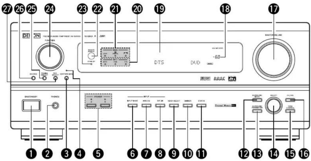
6 PART NAMES AND FUNCTIONS
Front Panel
- For details on the functions of these parts, refer to the pages given in parentheses ( ).
text_image
27 26 25 24 23 22 21 20 19 18 17 DE SN PROTECH IN AUSIN COMPONENT (AIS DIMENSION) FUNCTION DC/DC/DC DTS DUD MASTER VOLUME -60 WHIP PACS DISTANCEY THOMES STORMER OUTPUT MODE ANALOG EXTR. IN VIEW SELECT ZIMMER STATUS FORUM MOUNT RUSTABLE SELECT RUNNING PAMS TOTAL CONTROL 1 2 3 4 5 6 7 8 9 10 11 12 13 14 15 161 Power ON/STANDBY switch .....(31)
② Headphones jack (PHONES) .....(34)
③ Tape monitor button (CDR/TAPE MON)....(32)
4 Tape monitor indicator .....(32)
5 Front speaker system selector buttons (SPEAKER A/B) .....(31)
6 INPUT MODE button .....(32)
7 ANALOG button....(32)
8 EXT. IN button .....(35)
9 VIDEO SELECT button .....(34)
10 DIMMER button....(34)
11 STATUS button .....(34)
12 SURROUND MODE button .....(37)
13 SURROUND PARAMETER button .....(42)
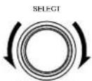
14 SELECT knob .....(33)
15 TONE CONTROL button .....(33)
16 CH. VOL button (36)
17 MASTER VOLUME control .....(33)
18 Master volume indicator (VOLUME LEVEL) .....(33)
19 Display
20 INPUT indicators .....(33)
21 SIGNAL indicator ....(33)
22 Remote control sensor (REMOTE SENSOR) .....(23)
23 Power indicator .....(31)
24 FUNCTION knob .....(32)
25 TUNING PRESET button .....(47)
26 SOURCE selector button .....(32)
27 REC SELECT button ..... (35)
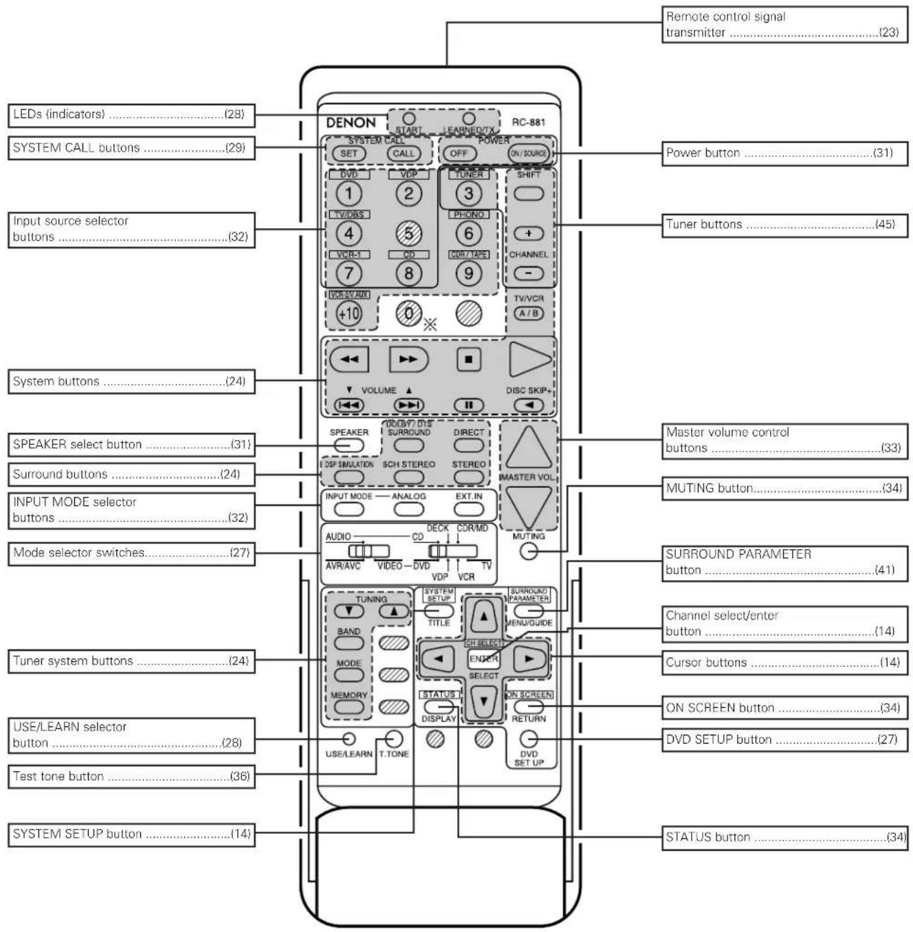
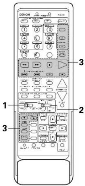
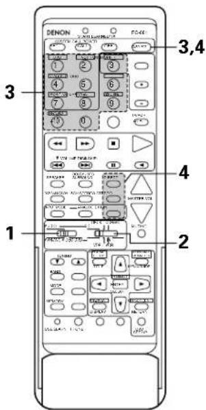
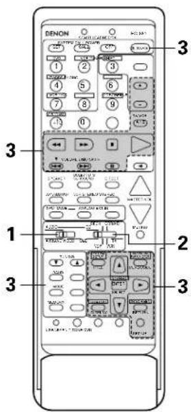
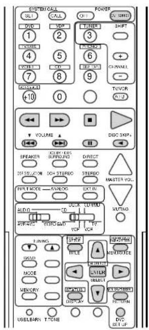
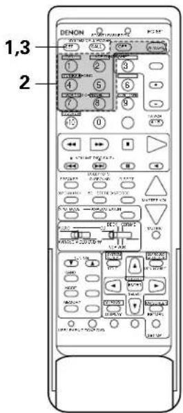
Remote control unit
- For details on the functions of these parts, refer to the pages given in parentheses ( ).
text_image
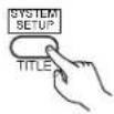
Remote control signal transmitter ....(23) LEDs (indicators) ....(28) SYSTEM CALL buttons ....(29) Input source selector buttons ....(32) System buttons ....(24) SPEAKER select button ....(31) Surround buttons ....(24) INPUT MODE selector buttons ....(32) Mode selector switches....(27) Tuner system buttons ....(24) USE/LEARN selector button ....(28) Test tone button ....(36) SYSTEM SETUP button ....(14) DENON START LEARNED/TX RC-881 SET CALL OFF ON/SOURCE DVD VDP TUNER SHIFT 1 2 3 TV/DAS LPHONO + VCR-1 CD CDR/TAPE CHANNEL 7 8 9 - VCR/SY AUX TV/VCR A/B +10 0 ※ VOLUME DISC SKIP+ SPEAKER DIRECT DSP SIMULATION SCH.STEREO STEREO MASTER VOL. INPUT MODE ANALOG EXT.IN AUDIO CD COR/MD MUTING AVR/AVC VIDEO DVD TV VCR TUNING SYSTEM SETUP SURROUND PARAMETER BAND TITLE MENU/GUIDE MODE CH SELECT MEMORY SELECT STATUS ON SCREEN DISPLAY RETURN DVDS SET UP Power button ....(31) Tuner buttons ....(45) Master volume control buttons ....(33) MUTING button ....(34) SURROUND PARAMETER button ....(41) Channel select/enter button ....(14) Cursor buttons ....(14) ON SCREEN button ....(34) DVD SETUP button ....(27) STATUS button ....(34)NOTE
- The shaded buttons do not function with the AVR-2801/981. (Nothing happens when they are pressed.) The button indicated, however, can be used with the learning function.
7 SETTING UP THE SYSTEM
- Once all connections with other AV components have been completed as described in "CONNECTIONS" (see pages 6 to 11), make the various settings described below on the monitor screen using the AVR-2801/981's on-screen display function. These settings are required to set up the listening room's AV system centered around the AVR-2801/981.
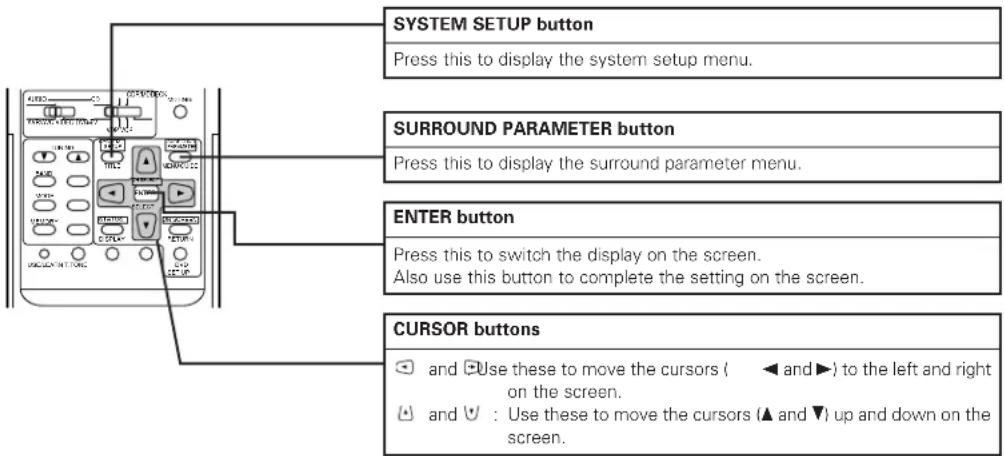
- Use the following buttons to set up the system:
text_image
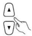
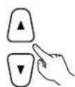
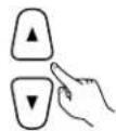
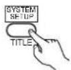
SYSTEM SETUP button Press this to display the system setup menu. SURROUND PARAMETER button Press this to display the surround parameter menu. ENTER button Press this to switch the display on the screen. Also use this button to complete the setting on the screen. CURSOR buttons ✓ and □ Use these to move the cursors ( ◀ and ▶) to the left and right on the screen. ◀ and ▼ : Use these to move the cursors (▲ and ▼) up and down on the screen.- System setup items and default values (set upon shipment from the factory)
| System setup | Default settings | |||||||||||
| 1 | Speaker Configuration | Input the combination of speakers in your system and their corresponding sizes (SMALL for regular speakers, LARGE for full-size, full-range) to automatically set the composition of the signals output from the speakers and the frequency response. | Front Sp. | Center Sp. | Surround Sp. | Subwoofer | ||||||
| Large | Small | Small | Yes | |||||||||
| Subwoofer mode | This selects the subwoofer speaker for playing deep bass signals. | LFE | ||||||||||
| 2 | Delay Time | This parameter is for optimizing the timing with which the audio signals are produced from the speakers and subwoofer according to the listening position. | Front & Subwoofer | Center | Surround L & R | — | ||||||
| 3.6 m (12 ft) | 3.6 m (12 ft) | 3.0 m (10 ft) | — | |||||||||
| 3 | Channel Level | This adjusts the volume of the signals output from the speakers and subwoofer for the different channels in order to obtain optimum effects. | Front L | Front R | Subwoofer | Center | Surround L | Surround R | — | — | ||
| 0 dB | 0 dB | 0 dB | 0 dB | 0 dB | 0 dB | — | — | |||||
| 4 | Digital In Adjustment | This assigns the digital input jacks for the different input sources. | Input source | CD | DVD | VDP | TV/DBS | VCR-1 | VCR-2/V. AUX | — | — | |
| Digital Inputs | COAXIAL | OPTICAL 1 | OPTICAL 2 | OPTICAL 3 | OFF | OFF | — | — | ||||
| 5 | On Screen Display | This sets whether or not to display the on-screen display that appears on the monitor screen when the controls on the remote control unit or main unit are operated (from MONITOR outputs only). | On Screen Display = ON | |||||||||
| 6 | Auto Tuner Presets | FM stations are received automatically and stored in the memory. | A1 ~ A8 | 87.5/89.1/98.1/107.9/90.1/90.1/90.1/90.1 MHz | ||||||||
| B1 ~ B8 | 520/600/1000/1400/1500/1710 kHz/90.1/90.1 MHz | |||||||||||
| C1 ~ C8 | 90.1 MHz | |||||||||||
| D1 ~ D8 | 90.1 MHz | |||||||||||
| E1 ~ E8 | 90.1 MHz | |||||||||||
NOTES:
- The on-screen display signals are output with priority to the S-VIDEO MONITOR OUT jack during playback of a video component. For example, if the TV monitor is connected to both the AVR-2801/981's S-Video and video monitor output jacks and signals are input to the AVR-2801/981 from a video source (VDP, etc.) connected to both the S-Video and video input jacks, the on-screen display signals are output with priority to the S-Video monitor output. If you wish to output the signals to the video monitor output jack, do not connect a cord to the S-VIDEO MONITOR OUT jack. (For details, see page 22.)
- The AVR-2801/981's on-screen display function is designed for use with high resolution monitor TVs, so it may be difficult to read small characters on TVs with small screens or low resolutions.
- The setup menu is not displayed when "HEADPHONE ONLY" is selected.
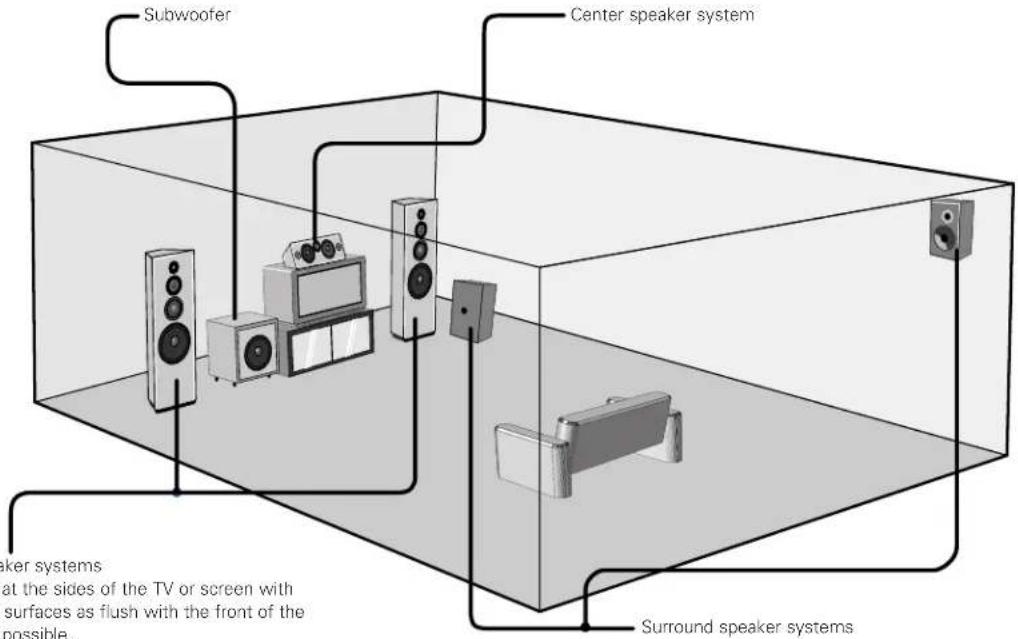
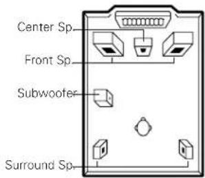
Speaker system layout
Basic system layout
• The following is an example of the basic layout for a system consisting of six speaker systems and a television monitor:
text_image
Subwoofer Center speaker system Surround speaker systems at the sides of the TV or screen with surfaces as flush with the front of the possible.Before setting up the system
1 Check that all the connections are correct, then turn on the main unit's power.
2 SYSTEM SETUP Display the System Setup Menu.
System Setup Menu
☐Speaker Configuration Delay Time
Channel Level
Digital In Assignment
On Screen Display
Auto Tuner Presets
Setting the type of speakers
- The composition of the signals output from the different channels and the frequency response are adjusted automatically according to the combination of speakers actually being used.
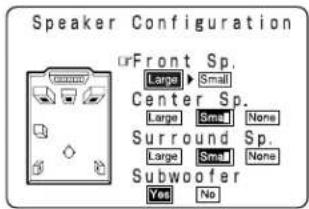
At the System Setup Menu select "Speaker Configuration".

2 ENTER Switch to the speaker configuration screen.

3
Set whether or not speakers are connected and, if so, their size parameters.
• To select the speaker
text_image
Speaker Configuration Front Sp. Large ▶ Small Center Sp. Large ▶ Small None Surround Sp. Large ▶ Small None Subwoofer Yes No
• To select the parameter
text_image
Center Sp Front Sp Subwoofer Surround Sp4

Enter the setting.
When "Front" is set to "Large" and "Subwoofer" is set to "Yes" the set switches to the subwoofer mode.
NOTE:
- Select "Large" or "Small" not according to the actual size of the speaker but according to the speaker's capacity for playing low frequency (approximately 80 Hz and below) signals. If you do not know, try comparing the sound at both settings (setting the volume to a level low enough so as not to damage the speakers) to determine the proper setting.
- Parameters
Large..... Select this when using speakers that can fully reproduce low sounds of below 80 Hz.
Small..... Select this when using speakers that cannot reproduce low sounds of below 80 Hz with sufficient volume.
When this setting is selected, low frequencies of below 80 Hz are assigned to the subwoofer.
None..... Select this when no speakers are installed.
Yes/No.... Select "Yes" when a subwoofer is installed, "No" when a subwoofer is not installed.
* If the subwoofer has sufficient low frequency playback capacity, good sound can be achieved even when "Small" is set for the front, center and surround speakers.
* For the majority of speaker system configurations, using the SMALL setting for all five main speakers and Subwoofer On with a connected subwoofer will yield the best results.
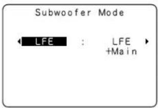
Setting the subwoofer mode
1

Select the bass signal playback mode.
text_image
Subwoofer Mode LFE : LFE +Main2

Enter the setting.
The System Setup Menu reappears.
NOTES:
- In the Subwoofer mode screen, you have the flexibility to choose how bass information is distributed to your speakers if you have large front left and right speakers and a subwoofer as part of your home theater speaker system.
- By selecting the "LFE + Main" option, you will be sending the same bass frequencies to both the front left, front right, and the subwoofer speakers simultaneously. Depending upon your room size and shape, this can create a more evenly distributed bass around the room or sometimes actually decrease the amount of bass in the room due to low frequency cancellations.
- If the "LFE" option is selected, bass from the large front left and front right speakers goes only to the front left and front right speakers. Bass going to the subwoofer comes from the LFE signal and any speakers which you have designated as "Small." This selection is preferred as it reduces the chances of bass cancellations in the room.
- Once you have positioned all of your speakers in the room, choose the option which gives you the most solid sounding bass.
- When the subwoofer is set to "Yes", bass sound is output from the subwoofer regardless of the subwoofer mode setting in surround modes other than Dolby/DTS.
Setting the delay time
Input the distances from the listening position to the speakers and set the surround delay time.
Preparations:
Measure the distances from the listening position to the speakers (L1 to L3 on the diagram at the right).
L1: Distance from center speakers to listening position
L2: Distance from front speakers to listening position
L3: Distance from rear speakers to listening position
NOTES:
- Set the center speaker so that the distance to the front speakers (left and right) or the subwoofer is the same (L2 = L1) or so that the difference in the distance (L2 - L1) is 5 feet (1.5 meters) or less.
- Set the surround speakers (left and right) so that the distance to the front speakers (left and right) or the subwoofer is the same (L2 = L3) or so that the difference in the distance (L2 - L3) is 15 feet (4.5 meters) or less.

flowchart
graph TD
    FL["FL"] --> L1["L1"]
    Center["Center"] --> L2["L2"]
    FR["FR"] --> L3["L3"]
    SL["SL"] --> L1
    SL --> L3
    L1 --> Center
    L2 --> Center
    L3 --> Center
    Center -->|Listening position| L1
    Center -->|Listening position| L2
    Center -->|Listening position| L3
1

At the System Setup Menu select "Delay Time".
System Setup Menu
Speaker Configuration Delay Time Channel Level Digital In Assignment On Screen Display Auto Tuner Presets
2

Switch to the Delay Time screen.
Delay Time
Set The Distance To Each Speakers
Do You Prefer In Meters? / In Feet?
Meters ◀:▶ Feet
3

Select the desired unit, meters or feet.
Select (darken) the desired units, "Meters" or "Feet".
Delay Time
Set The Distance To Each Speakers
Do You Prefer In Meters? / In Feet?
□Meters ◀:▶ Feet
Example: When "Feet" is selected
4 Once "Meters" or "Feet" is selected in step 3, the Delay Time screen appears automatically.
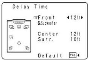
text_image
Delay Time Front & Subwoofer 12ft Center 12ft Surr. 10ft Default Yes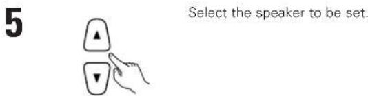
text_image
5 Select the speaker to be set.6 Set the distance between the center speaker and listening position. The distance changes in units of 1 foot (0.1 meters) each time the button is pressed. Select the value closest to the measured distance.
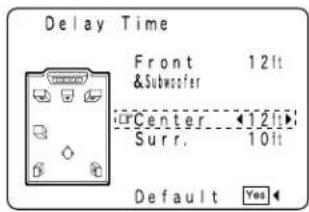
text_image
Delay Time Front 12lt & Subwoofer Center 12lt Surr. 10lt Default YesExample: When the distance is set to 12 feet for the center speaker (L1)

* If "Yes" is selected for "Default", the settings are automatically reset to the default values.
* If you set an invalid distance, a CAUTION notice, such as screen right will appear. In this case, please relocate the blinking speaker(s) so that its distance is no larger than the value shown in highlighted line.
* Set in such a way that the distance to the center speaker is the same as or up to 5 feet (1.5 meters) shorter than the distance to the front speakers and the subwoofer.
* Set in such a way that the distance to the surround speakers is the same as or up to 15 feet (4.5 meters) shorter than the distance to the front speakers and the subwoofer.
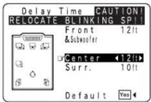
text_image
Delay Time CAUTION! RELOCATE BLINKING SP!! Front 12ft &Subwoofer Center 12ft Surr. 10ft Default Yes7 Enter the setting. The System Setu

The AVR-2801/981 automatically sets the optimum surround delay time for the listening room.
NOTE: - If the distance unit is changed after the delay time is set, the settings are reset to the factory default values (see page 14).
Setting the channel level
- Use this setting to adjust so that the playback level between the different channels is equal.
• From the listening position, listen to the test tones produced from the speakers to adjust the level. - The level can also be adjusted directly from the remote control unit. (For details, see page 36.)
1
At the System Setup Menu select "Channel Level".
System Setup Menu
Speaker Configuration Delay Time Channel Level Digital In Assignment On Screen Display Auto Tuner Presets
2

Switch to the Channel Level screen.
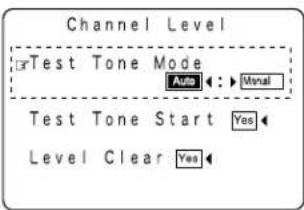
Channel Level
Test Tone Mode Auto ← → Moral Test Tone Start Yes Level Clear Yes
3
Select "Test Tone Mode".
4

Select the mode.
Select "Auto" or "Manual".
- Auto: Adjust the level while listening to the test tones produced automatically from the different speakers.
- Manual: Select the speaker from which you want to produce the test tone to adjust the level.
text_image
Channel Level OrTest Tone Mode Auto ←: ▶ Monal Test Tone Start Yes Level Clear YesExample: When the "Auto" mode is selected
5

Select "Test Tone Start".
6

Select "Yes".
Channel Level
Test Tone Mode Auto : ▶ Monal rTest Tone Start Yes Level Clear Yes
7
a. If the "Auto" mode is selected:
Test tones are automatically emitted from the different speakers. The test tones are emitted from the different speakers in the following order, at 4-second intervals the first time and second time around, 2-second intervals the third time around and on:

Use the CURSOR buttons to adjust all the speakers to the same volume.
The volume can be adjusted between -12 dB and +12 dB in units of 1 dB.
Flashing
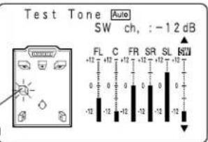
text_image
Test Tone Auto SW ch, :-12 dB FL C FR SR SL BW +12 +12 +12 +12 +12 +12 0 0 0 0 0 0 -12 -12 -12 -12 -12 -12Example: When the volume is set to -12 dB while the test tone is being produced from the subwoofer

b. When the "Manual" mode is selected
Use the and cursor buttons to select the speaker from which you want to produce the test tone, then use the and cursor buttons to adjust so that the volume from the different speakers sounds the same.
Flashing
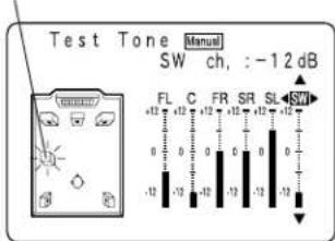
text_image
Test Tone Manual SW ch, :-12 dB FL C FR SR SL SW +12 +12 -12 0 0 0 0 0 0 0 -12 -12 -12 -12 -12Example: When the volume is set to -12 dB while the subwoofer is selected
8

After the above settings are completed, press the ENTER button.
The "Channel Level" screen reappears.
Press the ENTER button again, the "System Setup Menu" screen reappears.
* To cancel the settings, select "Level Clear" and "Yes" on the "Channel Level" screen, then make the settings again.
The level of each channel should be adjusted to 75 dB (C-weighted, slow meter mode) on a sound level meter at the listening position. If a sound level meter is not available adjust the channels by ear so the sound levels are the same. Because adjusting the subwoofer level test tone by ear is difficult, use a well known music selection and adjust for natural balance.
NOTE: When adjusting the level of an active subwoofer system, you may also need to adjust the subwoofer's own volume control.
* When you adjust the channel levels while in the SYSTEM SETUP CHANNEL LEVEL mode, the channel level adjustments made will affect ALL surround modes. Consider this mode a Master Channel Level adjustment mode.
* After you have completed the SYSTEM SETUP CHANNEL LEVEL adjustments, you can then activate the individual surround modes and adjust channel levels that will be remembered for each of those modes. Then, whenever you activate a particular surround sound mode, your preferred channel level adjustments for just that mode will be recalled. Check the instructions for adjusting channel levels within each surround mode on Page 36.
* You can adjust the channel levels for each of the following surround modes: DIRECT, STEREO, 5CH STEREO, DOLBY/DTS SURROUND, ROCK ARENA, JAZZ CLUB, VIDEO GAME, MONO MOVIE, and MATRIX.
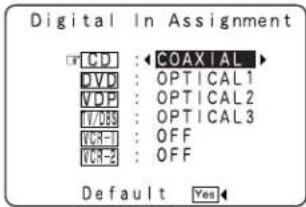
Setting the digital in assignment
- This setting assigns the digital input jacks of the AVR-2801/981 for the different input sources.
1
At the System Setup Menu select "Digital In Assignment".
System Setup Menu
Speaker Configuration Delay Time
Channel Level Digital In Assignment On Screen Display Auto Tuner Presets
2

Switch to the Digital In Assignment screen.
text_image
Digital In Assignment CD : ←COAXIAL DVD : OPTICAL1 VDP : OPTICAL2 VCP : OPTICAL3 ICR-1 : OFF ICR-2 : OFF Default Yes3


Select the digital input jack to be assigned to the input source.
• To select the input source
• To select the digital input jack
Select "OFF" for input sources for which no digital input jacks are used.
* If "Yes" is selected for "Default", the settings are automatically reset to the default values.
4

Enter the setting.
The System Setup Menu reappears.
NOTE:
- "PHONO", "CDR/TAPE" and "TUNER" cannot be selected on the Digital Inputs screen.
Setting the on-screen display (OSD)
- Use this to turn the on-screen display (messages other than the menu screens) on or off.
1

At the System Setup Menu select "On Screen Display".
System Setup Menu
Speaker Configuration
Delay Time
Channel Level
Digital In Assignment
On Screen Display
Auto Tuner Presets
2

Switch to the On Screen Display screen.
On Screen Display

3

Select "ON" or "OFF".
4

Enter the setting.
The System Setup Menu reappears.
Auto tuner presets
Use this to automatically search for FM broadcasts and store up to 40 stations at preset channels A1 to 8, B1 to 8, C1 to 8, D1 to 8 and E1 to 8.
NOTE:
- If an FM station cannot be preset automatically due to poor reception, use the "Manual tuning" operation to tune in the station, then preset it using the manual "Preset memory" operation.
1
Use the CURSOR buttons to specify "Auto Tuner Presets" from the "System Setup Menu" screen.
System Setup Menu
Speaker Configuration Delay Time Channel Level Digital In Assignment On Screen Display Auto Tuner Presets
2

Press the ENTER button. The "Auto Preset Memory" screen appears.
Auto Preset Memory
Auto Tuning & Preset Station Memory Storing Preset Memory
Start

3

Use the CURSOR button to select "Yes". "Search" flashes on the screen and searching begins. "Completed" appears once searching is completed. The display automatically switches to screen.
* This completes system setup. Once these settings are made, there is no need to change them unless different AV components are connected or the speakers are repositioned.
After completing system setup
This button can be pressed at any time during the system setup process to complete the process.
1
At the System Setup Menu, press the SYSTEM SETUP button. * The changed settings are entered and the on-screen display turns off.
- On-screen display signals
| Signals input to the AVR-2801/981 | On-screen display signal output | |||
| VIDEO signal input jack (yellow) | S-video signal input jack | VIDEO MONITOR OUT video signal output jack (yellow) | S-video MONITOR OUT video signal output jack | |
| 1 | × | × | ○ | ○ |
| 2 | ○ | × | ○ | × |
| 3 | × | ○ | × | ○ |
| 4 | ○ | ○ | × | ○ |
(O: Signal
×: No signal)
(C): On-screen signals output
×: On-screen signals not output)
NOTE:
- For 4 above, the on-screen display signals are output to the VIDEO MONITOR OUT video signal output jack (yellow) if the monitor TV is not connected to the S-video MONITOR OUT video signal output jack.
8 REMOTE CONTROL UNIT
- The included remote control unit (RC-881) can be used to operate not only the AVR-2801/981 but other remote control compatible DENON components as well. Furthermore, it is equipped with a function for learning the control signals of remote control units of other manufacturers, so it can also be used to operate non-DENON remote control compatible video components.
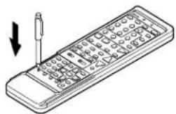
Inserting the batteries
① Remove the remote control unit's rear cover.
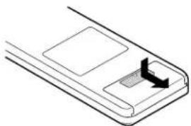
natural_image
Pure diagram of a mechanical component with no text, numbers, or symbols② Set two R6P/AA batteries in the battery compartment in the indicated direction.
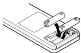
natural_image
Technical line drawing of a mechanical assembly with a clamping tool (no text or symbols)③ Put the rear cover back on.
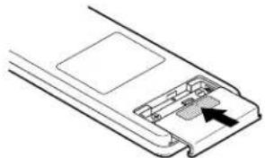
natural_image
Diagram of a device's internal structure showing a handle and internal components (no text or symbols)Notes on Batteries
- Use R6P/AA batteries in the remote control unit.
- The batteries should be replaced with new ones approximately once a year, though this depends on the frequency of usage.
- Even if less than a year has passed, replace the batteries with new ones if the set does not operate even when the remote control unit is operated nearby the set.
-
When inserting the batteries, be sure to do so in the proper direction, following the "⊖" and "⊖" marks in the battery compartment.
• To prevent damage or leakage of battery fluid: -
Do not use a new battery together with an old one.
- Do not use two different types of batteries.
- Do not short-circuit, disassemble, heat or dispose of batteries in flames.
- Remove the batteries from the remote control unit when you do not plan to use it for an extended period of time.
- If the battery fluid should leak, carefully wipe the fluid off the inside of the battery compartment and insert new batteries.
- When replacing the batteries, have the new batteries ready and insert them as quickly as possible.
- The learned remote control signals may be cleared if no batteries are in the remote control unit for about 5 seconds.
The factory-installed codes are in permanent memory, however.
Using the remote control unit
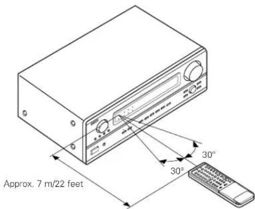
text_image
Approx. 7 m/22 feet 30° 30°- Point the remote control unit at the remote sensor on the main unit as shown on the diagram.
- The remote control unit can be used from a straight distance of approximately 7 meters/22 feet from the main unit, but this distance will be shorter if there are obstacles in the way or if the remote control unit is not pointed directly at the remote sensor.
- The remote control unit can be operated at a horizontal angle of up to 30 degrees with respect to the remote sensor.
NOTES:
- It may be difficult to operate the remote control unit if the remote sensor is exposed to direct sunlight or strong artificial light.
- Do not press buttons on the main unit and remote control unit simultaneously. Doing so may result in malfunction.
- Neon signs or other devices emitting pulse-type noise nearby may result in malfunction, so keep the set as far away from such devices as possible.
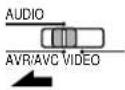
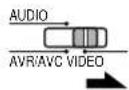
Operating DENON audio components
- Turn on the power of the different components before operating them.
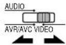
1
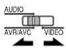
Set mode switch 1 to "AUDIO (AVR/AVC)".
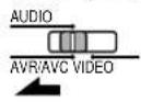
2
Set mode switch 2 to the position for the component to be operated.
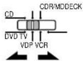
text_image
DENON 1 2 3 4 5 6 7 8 9 10 11 12 13 14 15 16 17 18 19 20 21 22 23 24 25 26 27 28 29 30 31 32 33 34 35 36 37 38 39 40 41 42 43 44 45 46 47 48 49 50 51 52 53 54 55 56 57 58 59 60 61 62 63 64 65 66 67 68 69 70 71 72 73 74 75 76 77 78 79 80 81 82 83 84 85 86 87 88 89 90 91 92 93 94 95 96 97 98 99 1003
Operate the audio component.
- For details, refer to the component's operating instructions.
* While this remote control is compatible with a wide range of infrared controlled components, some models of components may not be operated with this remote control.
- CD player (CD) and CD recorder and MD recorder (CDR/MD) system buttons
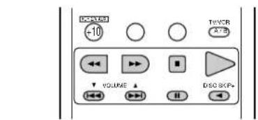
text_image
DCR -10 TIME AT=5 VOLUME DISO SKIP+
: Manual search (forward and reverse)

: Stop

: Play

: Auto search (cue)

: Pause
DISC
: Switch discs
SKIP+
(for CD changers only)
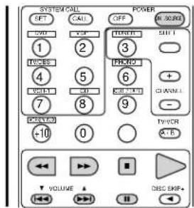
- Tuner system buttons
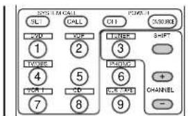
text_image
SYSTEM CALL SQL CALL C11 RESET YOU XOF TURER SHIFT 1 2 3 TWOORE 4 5 PHASE 6 VOR 1 CD VOR 1/2 CHANNEL 7 8 9SHIFT
: Switch preset channel range
CHANNEL
: Preset channel
+,-
up/down
- Tape deck (DECK) system buttons
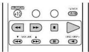
text_image
+10 VOLUME USB2 STEP4: Rewind
▶ : Fast-forward
■ : Stop
▶ : Forward play
II : Pause
◀ : Reverse play
A/B : Switch between decks A and B
* For the tuner only, the following buttons can also be operated:
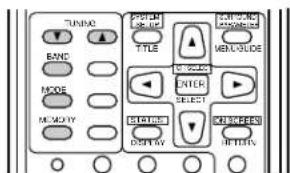
text_image
TUNION BAND MODE MEMORY TITLE TITLE ENTER SELECT TITLE RESET TITLE CONTROL MANAGEMENT MENGLISH ENTER SELECT TITLE RETURNTUNING : Frequency

up/down
BAND : Switch between the AM and FM bands
MODE : Switch between auto and mono
MEMORY : Preset memory
Preset memory (Audio component)
- DENON components can be operated by setting the preset memory for CDR or MD. Operation is not possible for some models, however. In this case use the learning function (see page 28) to store the remote control signals.
- For instructions on clearing the presettings stored in the preset memory, see page 31.
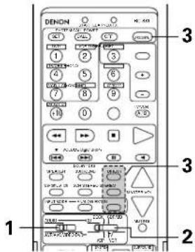
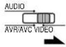
1
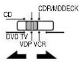
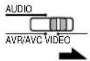
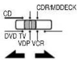
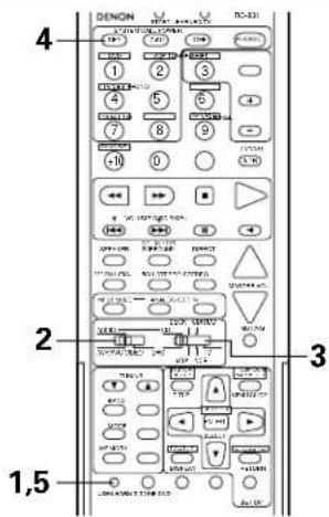
Set the slide switch to "AUDIO".
2
Set the slide switch to "CDR/MD.
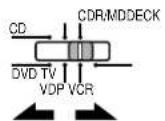
( Keep the POWER button pressed in when performing steps 3 and 4 )
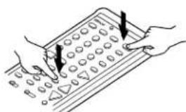
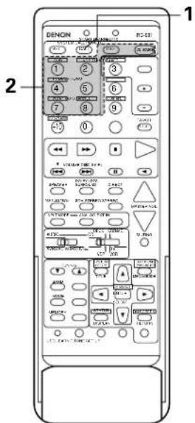
3
Holding in the POWER button, press the button for the components you want to set.
text_image
Illustration showing hands using a calculator with numeric keypad and pointer arrows indicating function calloutsThe LEARNED/TX LED flashes.
text_image
DENON 1 2 3 4 5 6 7 8 9 10 11 12 13 14 15 16 17 18 19 20 21 22 23 24 25 26 27 28 29 30 31 32 33 34 35 36 37 38 39 40 41 42 43 44 45 46 47 48 49 50 51 52 53 54 55 56 57 58 59 60 61 62 63 64 65 66 67 68 69 70 71 72 73 74 75 76 77 78 79 80Combinations of Personal System Codes
"CDR/MD"
| DIRECT(DIRECT) | STREO(STEREO) | EXTN(EXT. IN) | |
| (Power) | DENON CDR A | DENON CDR B | DENON MD |


Preset codes set upon shipment from the factory.
Preset memory (Video component)
- DENON and other makes of components can be operated by setting the preset memory for your make of video component. Operation is not possible for some models, however. In this case use the learning function (see page 28) to store the remote control signals.
- For instructions on clearing the presettings stored in the preset memory, see page 31
1
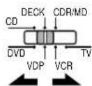
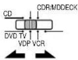
Set the slide switch to "VIDEO".
2
Set the slide switch to the component to be registered (DVD, VDP, VCR or TV).
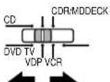
( Keep the POWER button pressed in when performing steps 3 and 4 )
3
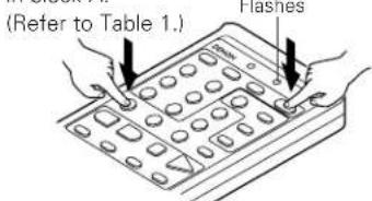
Holding in the POWER button, press the button for the corresponding manufacturer in block A.
text_image
(Refer to Table 1.) FlashesThe LEARNED/TX LED flashes.
4
Next, while holding the POWER button, press the button for the code in block B. (Refer to Table 1.) The operation is completed when the button is released and the LEARNED/TX LED lights.

text_image
Illustration showing hands using a calculator with numeric keypad and directional arrows indicating function call5
To continue registering other components, repeat steps 2 to 4.
text_image
1 2 3 4 5 6 7 8 9 10 11 12 13 14 15 16 17 18 19 20 21 22 23 24 25 26 27 28 29 30 31 32 33 34 35 36 37 38 39 40 41 42 43 44 45 46 47 48 49 50 51 52 53 54 55 56 57 58 59 60 61 62 63 64 65 66 67 68 69 70 71 72 73 74 75 76 77 78 79 80 81 82 83 84 85 86 87 88 89 90 91 92 93 94 95 96 97 98 99 100- This remote control unit can be used to operate components of other manufacturers without using the learning function by registering the manufacturer of the component as shown on Table 1.
Table 1: Combinations of Personal System Codes for Different Manufacturers
"DVD"
| A\B | (DIRECT) | (STEREO) | (EXT. IN) |
| 1 (DVD) | DENON A | DENON B | — |
| 2 (VDP) | — | — | — |
| 3 (TUNER) | — | — | — |
| 4 (TV/DBS) | PANASONIC | — | — |
| 5 | — | — | — |
| 6 (PHONO) | SONY | — | — |
| 7 (VCR-1) | PIONEER | — | — |
| 8 (CD) | TOSHIBA | — | — |
| 9 (CDR/TAPE) | — | — | — |
| 10 (VCR/V.AUX) | — | — | — |
| 11 | — | — | — |
| 12 (SHIFT) | — | — | — |
| 13 (CHANNEL +I) | — | — | — |
| 14 (CHANNEL -) | — | — | — |
| 15 (A/B) | — | — | — |
"VDP"
| A\B | (DIRECT) | (STREO)(STEREO) | (EXT. IN) |
| 1 (DVD) | DENON A | DENON B | DENON C |
| 2 (VDP) | — | — | — |
| 3 (TUNER) | MITSUBISHI | — | — |
| 4 (TV/DBS) | PANASONIC | — | — |
| 5 | — | — | — |
| 6 (PHONO) | SONY A | SONY B | SONY C |
| 7 (VCR-1) | PIONEER | — | — |
| 8 (CD) | — | — | — |
| 9 (CDR/TAPE) | — | — | — |
| 10 (VCR/V.AUX) | — | — | — |
| 11 | — | — | — |
| SHIFT(SHIFT) | PHILIPS | — | — |
| + CHANNEL (CHANNEL +I) | RCA | — | — |
| CHANNEL (CHANNEL -) | — | — | — |
| A/B (A/B) | NAGNAVOX | — | — |
"VCR"
| A\B | (DIRECT) | (STEREO) | (EXT. IN) |
| 1 (DVD) | — | — | — |
| 2 (VDP) | HITACHI A | HITACHI B | — |
| 3 (TUNER) | MITSUBISHI A | MITSUBISHI B | MITSUBISHI C |
| 4 (TV/DBS) | PANASONIC A | PANASONIC B | PANASONIC C |
| 5 | JVC (VICTOR) A | JVC (VICTOR) B | JVC (VICTOR) C |
| 6 (PHONO) | SONY A | SONY B | SONY C |
| 7 (VCR-1) | PIONEER | — | — |
| 8 (CD) | TOSHIBA A | TOSHIBA B | — |
| 9 (CDR/TAPE) | SANYO A | SANYO B | — |
| 10 (VCR/V.AUX) | SHARP A | SHARP B | — |
| 11 | NEC A | NEC B | NEC C |
| 12 (SHIFT) | PHILIPS A | PHILIPS B | PHILIPS C |
| 13 (CHANNEL +) | RCA A | RCA B | — |
| 14 (CHANNEL -) | GENERAL ELECTRIC A | GENERAL ELECTRIC B | — |
| 15 (A/B) | NAGNAVOX A | NAGNAVOX B | NAGNAVOX C |
"TV"
| A\B | (DIRECT) | (STEREO) | (EXT. IN) |
| 1 (DVD) | — | — | — |
| 2 (VDP) | DENON/HITACHI | — | — |
| 3 (TUNER) | MITSUBISHI A | MITSUBISHI B | — |
| 4 (TV/DBS) | PANASONIC A | PANASONIC B | — |
| 5 | JVC (VICTOR) | — | — |
| 6 (PHONO) | SONY | — | — |
| 7 (VCR-1) | PIONEER | — | — |
| 8 (CD) | TOSHIBA | — | — |
| 9 (CDR/TAPE) | SANYO | — | — |
| 10 (VCR/V.AUX) | SHARP | — | — |
| 1 | NEC | — | — |
| SHIFT (SHIFT) | PHILIPS A | — | — |
| CHANNEL (CHANNEL -I) | RCA A | — | — |
| CHANNEL (CHANNEL -) | GENERAL ELECTRIC A | GENERAL ELECTRIC B | — |
| A/B (A/B) | NAGNAVOX A | — | — |

Preset codes set upon shipment from the factory.
NOTES:
- The signals for the pressed buttons are emitted while setting the preset memory. To avoid accidental operation, cover the remote control unit's transmitting window while setting the preset memory.
- Some models and years of manufacture of components of the manufacturers listed on Table 1 cannot be used.
- The signals stored at "learned" buttons have priority over the preset codes. If you wish to clear the "learned" signals, do so as described on page 31.
- Some manufacturers use different types of remote control codes for their products. If the component does not operate when set to remote codeset A, try setting to the B or C codesets.
Operating a video component stored in the preset memory
1
Set the slide switch to "VIDEO".
2
Set the slide switch to the component to be registered (DVD, VDP, VCR or TV).
text_image
DENON 1 2 3 4 5 6 7 8 9 10 11 12 13 14 15 16 17 18 19 20 21 22 23 24 25 26 27 28 29 30 31 32 33 34 35 36 37 38 39 40 41 42 43 44 45 46 47 48 49 50 51 52 53 54 55 56 57 58 59 60 61 62 63 64 65 66 67 68 69 70 71 72 73 74 75 76 77 78 79 80 81 82 83 84 85 86 87 88 89 90 91 92 93 94 95 96 97 98 99 1003
Operate the video component.
- For details, refer to the component's operating instructions.
* Some models cannot be operated with this remote control unit.
1. DVD player system buttons
text_image
SYSTEM CALL SLI CALL POWER OUT VAND DVD VDF LINDER SHIFT 1 2 3 4 5 6 7 8 9 CHANNEL +10 0 TVCOR VCL-2 VOLUME DISC SKIP+ SPEAKER IKRY-DCS SURROUND DIRECT OFF/FLU/ON SOH STEREO STEREO INPUT MODE - ANNLOG EXT IN MASTER VOL. AUDIO - UCR - LUTMID APPRO - VERS/LOD VDF VDF VIF VOUTING TUNING - TITLE - NUMBER - MENU - SELECT - MEMORY - INJALIS - DISPLAY - EXCELGENE- PULDER USELEARN T-TONE DVD SET UP| POWER : Turns power on and off(ON/SOURCE) | |
| ◀◀,▶▶ | : Manual search (forward and reverse) |
| ■ | : Stop |
| ▶ | : Play |
| ◀◀,▶▶I | : Auto search (cue) |
| ■■ | : Pause |
| SKIP + | : (for DVD changers only) |
| TITLE : Call out title | |
| MENU : Call out menu | |
| DISPLAY : Switch display | |
| DVD SET UP: DVD setup | |
| RETURN : Menu return | |
| ▲,▼ | : Cursor up/down |
| ◀,▶ | : Cursor left/right |
SELECT : Enter setting
NOTE:
Some manufacturers use different names for the DVD remote control buttons, so also refer to the instructions on remote control for that component.
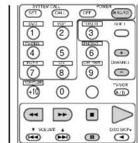
2. Video disc player (VDP) system buttons
text_image
SYSTEM CALL SET CALL OFF M/SOIRS 1 2 3 THEREY + - TW/SEE 4 5 6 + - VOUT 7 8 9 GNDINI - POTATO -10 0 TV/VER A+B VOLUME DISC EMF+POWER : Power on/off (ON/SOURCE)
text_image
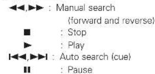
◀◀,▶▶ : Manual search (forward and reverse) ■ : Stop ▶ : Play ◀◀,▶▶: Auto search (cue) ■: Pause3. Video deck (VCR) system buttons
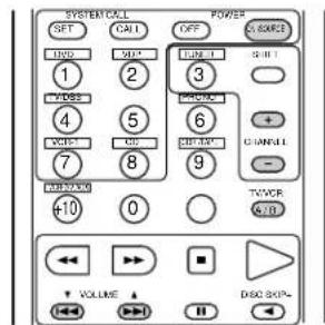
text_image
SYSTEM*ALL SPT CALL OFF DISCRE 1 2 3 4 5 6 7 8 9 TWOOR +10 0 A*B VOLUME DISO 8GPsPOWER : Power on/off
(ON/SOURCE)
text_image
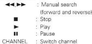
<<,▶▶ : Manual search (forward and reverse) ■ : Stop ▶ : Play ■: Pause CHANNEL : Switch channel4. Monitor TV system buttons
text_image
SYSTEM COOL SET CALL OFF GND 1 2 3 4 5 6 7 8 9 TWOOR +10 0 A/D VOLUME DISC 80% CHANNEL + - POWERPOWER : Power on/off (ON/SOURCE)
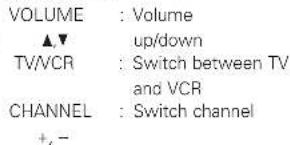
text_image
VOLUME : Volume ▲▼ up/down TV/VCR : Switch between TV and VCR CHANNEL : Switch channel +, -Learning function
- If your AV component is not a DENON product or it cannot be operated with the preset memory codesets, you can "teach" the AVR-2801/981's remote control to "learn" the codes from the component's original remote control.
- The buttons that can be "learned" are the CD, DECK and CDR/MD system buttons (see page 24) and the DVD, VDP, VCR and TV system buttons (see page 27). (For the CD, CDR/MD, DVD, VDP and TV, the A block buttons can also be "learned", and for the DVD and TV, the B block buttons can also be "learned".)
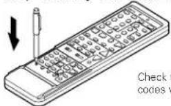
1 Press the USE/LEARN selector button with the tip of a pen etc., to set the learn mode. Both the START and LEARNED/TX indicators flash.
This unit's remote control unit
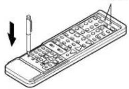
text_image
Diagram of a handheld electronic device with labeled pins and an arrow indicating direction, showing internal structure and component placement.2 Set the program switch to the side to be learned. Set to the AUDIO side for the CD, tape deck or CDR/MD position, to the VIDEO side for the DVD, VDP, VCR or TV position.
Set the program switch to the position to be learned.
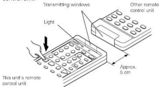
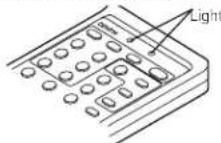
4 Set the remote control units so they are facing each other, then press the button to be learned on this unit's remote control unit.
text_image
Transmitting windows Light This unit's remote control unit Other remote control unit Approx. 5 cmThe indicator stops flashing and the START LED lights. The learnable buttons are the buttons which can be operated with the DENON system codes for the CD player, tape deck, CD recorder, MD recorder, the buttons which can be operated with the preset memory for the DVD, VCR, VDP and TV. For the TV only, however, the buttons in the section indicated "A" on the diagram above can also be "learned". Use these to "learn" TV channels.
text_image
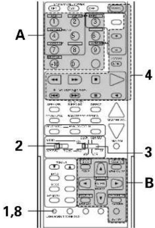
A 2 3 1,8 4 B5 Check that the START LED is lit, then press the button to be "learned" on the other remote control unit.
text_image
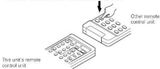
This unit's remote control unit Other remote control unit6 Once the START LED turns off and the LEARNED/TX LED lights, release the button on the other remote control unit.
text_image
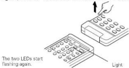
The two LEDs start flashing again. Light7 To "learn" other buttons, repeat steps 2 to 6.
8 Once the learning operation is completed, press the USE/LEARN selector button again. The two LEDs stop flashing and the learning mode is cancelled.
NOTES:
- Up to 26 codes can be "learned", but this number may be lower if the codes are long.
- If a non-learnable button is pressed or two or more buttons are pressed at once, the two LEDs will once again light when the button(s) is released.
- If the codes could not be stored, the LEARNED/TX LED does not light after the START LED turns off. For limited number of models, codes cannot be stored in RC-881.
- If the two LEDs start flashing rapidly after the START LED lights, this means that the memory is already full, and the code you have just attempted to store was not stored.
To "learn" that code, first perform the resetting operation. (See page 31.)
System call function
- The included remote control unit is equipped with a system call function for transmitting multiple remote control signals when a single button is pressed (this is often referred to as a "macro" function).
This function can be used to turn on the amplifier's power, select the input source, turn on the monitor TV's power, turn on a source component's power and start playback, etc., all at the touch of a button.
(1) System call buttons
The buttons that can be used for the system call function are shown on the table below.
A series of up to 10 operations can be performed with the POWER ON and OFF buttons, and a series of up to 5 operations can be performed with other buttons.
System call signals are already preset at the buttons indicated in the shaded section. System call signals can also be stored at any button on the remote control unit, including the buttons in this section. (See page 30.)
| Button | No. transmissions | Stored operation 1 | Stored operation 2 | Stored operation 3 | Stored operation 4 | Stored operation 5 | Stored operation 6 | Stored operation 7 | Stored operation 8 | Stored operation 9 | Stored operation 10 |
| POWER OFF 10 | |||||||||||
| POWER ON 10 | |||||||||||
| DVD 5 | Receiver power on | DVD player (DVD) power on | Receiver input source switched to DVD | TV power on | DVD player (DVD) playback | The system call signals for the POWER OFF and POWER ON buttons are transmitted from the remote control unit approximately once every second.The signals for the other buttons (DVD, VDP, TV / DBS, VCR-1 and CD) are transmitted approximately once every 1.5 seconds. | |||||
| VDP | 5 | Receiver power on | LD player (VDP) power on | Receiver input source switched to VDP | TV power on | LD player (VDP) playback | |||||
| TV/DBS | 5 | Receiver power on | TV power on | Receiver input source switched to TV/DBS | |||||||
| VCR-1 | 5 | Receiver power on | Video (VCR) power on | Receiver input source switched to VCR-1 | TV power on | Video (VCR) playback | |||||
| CD | 5 | Receiver power on | Receiver input source switched to CD | ||||||||
(2) Using the system call function
1 Press the system call button. • The LEARNED/TX LED flashes for 5 seconds.

2 Press the button at which the desired system call signals are stored while the LEARNED/TX LED is flashing.
- The preset signals or the signals you have stored at that button are transmitted in succession.
text_image
1 2 DENON DC-43 1 2 3 4 5 6 7 8 9 0 1 2 3 4 5 6 7 8 9 10 11 12 13 14 15 16 17 18 19 20 21 22 23 24 25 26 27 28 29 30 31 32 33 34 35 36 37 38 39 40 41 42 43 44 45 46 47 48 49 50 51 52 53 54 55 56 57 58 59 60 61 62 63 64 65 66 67 68 69 70 71 72 73 74 75 76 77 78 79 80(3) Storing signals (4) Clearing system call settings
text_image
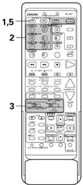
1,5 2 31 Press the SET button.
• The START LED and LEARNED/TX LED both flash.

2 Press the button at which you want to store the system call signals.
• The START LED flashes.
3 Set the mode switch to the position for the component whose remote control signals you want to store.
4 Press the buttons whose remote control signals you want to store one by one.
5 Press the SET button.

text_image
1,3 21 Press the SET button.

2 Press the button whose settings you want to clear.
Press the SET button.
- The button is reset to the settings shown on the table on page 29.

NOTES:
- The remote control signals for the buttons pressed while storing the system call signals are transmitted when the buttons are pressed, so cover the remote sensor or take other measures so that the components do not operate while the signals are being stored.
- The LEARNED/TX LED does not light if system call signals cannot be stored at the button that you have pressed or if you have already stored the maximum number of signals.
Clearing "learned" remote control signals
1 Press the USE/LEARN selector button with the tip of a pen, etc., to set the learn mode.
natural_image
Illustration of a handheld electronic device with a screwdriver inserted, showing internal components (no text or symbols)2 To clear "learned" remote control signals, set the slide switch to the position at which the signals were "learned".
3 Set the slide switch to the position at which the signals were "learned".
9 OPERATION
Before operating
1 Refer to "CONNECTIONS" (pages 6 to 11) and check that all connections are correct.
2 Set the remote control unit's slide switch to the AUDIO position. (only when operating with the remote control unit)
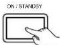
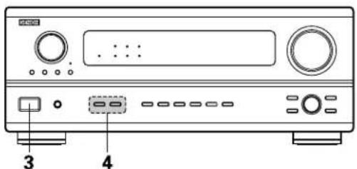
3 Turn on the power. Press the POWER switch (button).

(Main unit)
(Remote control unit)
When pressed, the power turns on and the display lights. The sound is muted for several seconds, after which the unit operates normally. When pressed again, the power turns off, the standby mode is set and the display turns off.
Whenever the ON/STANDBY button is in the STANDBY state, the apparatus is still connected on AC line voltage. Please be sure to unplug the cord when you leave home for, say, a vacation.
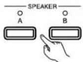
4 Select the front speakers. Press SPEAKER A or B turn the speaker on.
(Main unit)

(Remote control unit)
text_image
DENON DC-331 4 1 2 3 4 5 6 7 8 9 10 0 + VCC 100% Light 100% 2 3 2 3 1,54 Press the SYSTEM CALL SET button, and hold it in for at least four seconds.
- When both the START and LEARNED/TX LEDs light simultaneously, all the stored codes are cleared.

5 Press the USE/LEARN selector button.
text_image
Diagram of a CD-ROM front panel with labeled ports and buttons, showing front panel 3 and rear panel 4.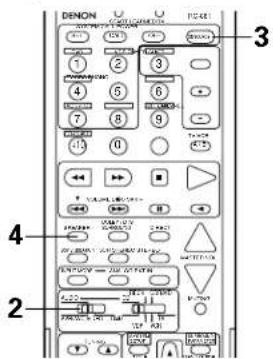
text_image
DENON 3 1 2 3 4 5 6 7 8 9 10 11 12 13 14 15 16 17 18 19 20 21 22 23 24 25 26 27 28 29 30 31 32 33 34 35 36 37 38 39 40 41 42 43 44 45 46 47 48 49 50 51 52 53 54 55 56 57 58 59 60 61 62 63 64 65 66 67 68 69 70 71 72 73 74 75 76 77 78 79 80 81 82 83 84 85 86 87 88 89 90 91 92 93 94 95 96 97 98 99 100Playing the input source
text_image
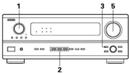
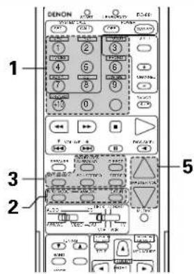
1 2 3 51
Select the input source to be played.
Example: CD

(Main unit) (Remote control unit)
* When the tape input (CDR/TAPE MON) is selected, the input indicator lights.
* To select the input source when REC SELECT or TUNING PRESET is selected, press the SOURCE button then operate the input function selector.

(Main unit)
2
Select the input mode.
- Selecting the analog mode
Press the ANALOG button to switch to the analog input.
(Main unit) (Remote control unit)

- Selecting the external input (EXT, IN) mode Press the EXT, IN to switch the external input.
(Main unit) (Remote control unit)

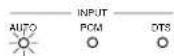
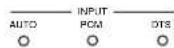
- Selecting the AUTO, PCM and DTS modes The mode switches as shown below each time the INPUT MODE button is pressed.
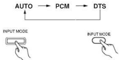
flowchart
graph TD
    A["AUTO"] --> B["PCM"]
    B --> C["DTS"]
    C --> A
    style A fill:#f9f,stroke:#333
    style B fill:#ccf,stroke:#333
    style C fill:#cfc,stroke:#333
    note1["INPUT MODE"] --> A
    note2["INPUT MODE"] --> C
(Main unit) (Remote control unit)
text_image
1 2 3 5 1 2 3 4 5 6 7 8 9 10 11 12 13 14 15 16 17 18 19 20 21 22 23 24 25 26 27 28 29 30 31 32 33 34 35 36 37 38 39 40 41 42 43 44 45 46 47 48 49 50 51 52 53 54 55 56 57 58 59 60 61 62 63 64 65 66 67 68 69 70 71 72 73 74 75 76 77 78 79 80 81 82 83 84 85 86 87 88 89 90 91 92 93 94 95 96 97 98 99 100Input mode selection function
Different input modes can be selected for the different input sources. The selected input modes for the separate input sources are stored in the memory.
① AUTO (auto mode)
In this mode, the types of signals being input to the digital and analog input jacks for the selected input source are detected and the program in the AVR-2801/981's surround decoder is selected automatically upon playback. This mode can be selected for all input sources other than PHONO, CDR/TAPE and TUNER. The presence or absence of digital signals is detected, the signals input to the digital input jacks are identified and decoding and playback are performed automatically in DTS, Dolby Digital or PCM (2 channel stereo) format. If no digital signal is being input, the analog input jacks are selected.
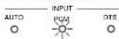
② PCM (exclusive PCM signal playback mode)
Decoding and playback are only performed when PCM signals are being input.
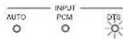
③ DTS (exclusive DTS signal playback mode)
Decoding and playback are only performed when DTS signals are being input.
④ ANALOG (exclusive analog audio signal playback mode)
The signals input to the analog input jacks are decoded and played.
⑤ EXT. IN (external decoder input jack selection mode)
The signals being input to the external decoder input jacks are played without passing through the surround circuitry.
NOTES:
- Note that noise will be output when CDs or LDs recorded in DTS format are played in the "PCM" (exclusive PCM signal playback) or "ANALOG" (exclusive analog audio signal playback) mode. Select the AUTO or DTS (exclusive DTS signal playback) mode when playing signals recorded in DTS from a laser disc player.
- Noise may be generated at the beginning of playback and while searching during DTS playback in the AUTO mode. If so, play in the DTS mode.
- In some rare cases noise may be generated when you preform the operation to stop playback of a DTS-CD or DTS-LD.
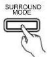
3
Select the play mode.
Press the SURROUND MODE button, then turn the SELECT knob.
Example: Stereo
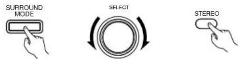
text_image
SURROUND MODE SELECT STEREO(Main unit) (Remote control unit)
* To select the surround mode while adjusting the surround parameters, channel volume or tone control, press the surround mode button then operate the selector.
(Main unit)
4
Start playback on the selected component.
- For operating instructions, refer to the component's manual.
5
Adjust the volume.
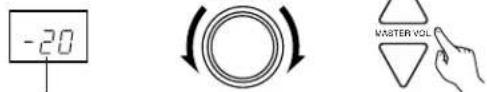
text_image
-20 MASTER VOL(Main unit) (Remote control unit)
The volume level is displayed on the master volume level display.
* The volume can be adjusted within the range of -60 to 0 to 18 dB, in steps of 1 dB. However, when the channel level is set as described on page 19 or pages 36 and 37, if the volume for any channel is set at +1 dB or greater, the volume cannot be adjusted up to 18 dB. (In this case the maximum volume adjustment range is "18 dB — (Maximum value of channel level)".)
Input mode when playing DTS sources
- Noise will be output if DTS-compatible CDs or LDs are played in the "ANALOG" or "PCM" mode.
When playing DTS-compatible sources, be sure to connect the source component to the digital input jacks (OPTICAL/COAXIAL) and set the input mode to "DTS".
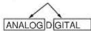
Input mode display
• In the AUTO mode
• In the DIGITAL PCM mode
• In the DIGITAL DTS mode
• In the ANALOG mode
One of these lights, depending on the input signal.


Input signal display
• DOLBY DIGITAL
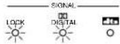
• DTS
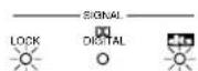
• PCM
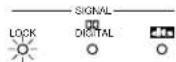
* The LOCK LED lights when digital signals are being input properly. If the LED does not light, check whether the digital input component setup (page 21) and connections are correct and whether the component's power is turned on.
NOTE:
- The digital input indicator will light when playing CD-ROMs containing data other than audio signals, but no sound will be heard.
After starting playback
[1] Adjusting the sound quality (tone)
The tone control function will not work in the direct mode.
1
The tone switches as follows each time the TONE CONTROL button is pressed.
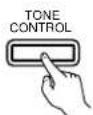
(Main unit)

2
With the name of the volume to be adjusted selected, turn the SELECT knob to adjust the level.
(Main unit)
- To increase the bass or treble: Turn the control clockwise. (The bass or treble sound can be increased to up to +12 dB in steps of 2 dB.)
- To decrease the bass or treble: Turn the control clockwise. (The bass or treble sound can be decreased to up to -12 dB in steps of 2 dB.)
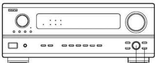
natural_image
Front view line drawing of a CD-ROM front panel with buttons and ports (no text or symbols)21
[2] Listening over headphones
1 Connect the headphones to the PHONES jack of the front panel.
![DENON AVR-981 - [2] Listening over headphones - 1](/content/2026/05/1070204/images/44e1c072f0e886fafbf50377e9122df62cb4f8bb414befa497368135395ac85e.jpg)
2 Press the SPEAKER A or B to turn the speaker off.
![DENON AVR-981 - [2] Listening over headphones - 2](/content/2026/05/1070204/images/46c9200ec22555afe7f314d33ed4ed993e2cad37e0b1c606bb57aa042ceb866a.jpg)
- The output to the speaker and pre-out jacks is turned off and no sound is produced from the speakers.
[3] Turning the sound off temporarily (muting)
1 Use this to turn off the audio output temporarily.
Press the MUTING button.
* Cancelling MUTING mode. Press the MUTING button again.
![DENON AVR-981 - [3] Turning the sound off temporarily (muting) - 1](/content/2026/05/1070204/images/bd0c3dec18268f733c9462b9330b79cd6556456d653667c8e30d047a8a3f89d9.jpg)
[4] Combining the currently playing sound with the desired image
1 Simulcast playback Use this switch to monitor a video source other than the audio source. Press the VIDEO SELECT button repeatedly until the desired source appears on the display.
* Cancelling simulcast playback.
- Select "SOURCE" using the video select button.
- Switch the program source to the component connected to the video input.
VIDEO SELECT
![DENON AVR-981 - [4] Combining the currently playing sound with the desired image - 1](/content/2026/05/1070204/images/ce836ec3f48156050fd7a34006f581bb921a10bbc13303dc3c703e013609d5c8.jpg)
(Main unit)
[5] Checking the currently playing program source, etc.
1 On screen display
- Each time an operation is performed, a description of that operation appears on the display connected to the unit's VIDEO MONITOR OUT jack. Also, the unit's operating status can be checked during playback by pressing the remote control unit's ON SCREEN button.
Such information as the position of the input selector and the surround parameter settings is output in sequence.
![DENON AVR-981 - [5] Checking the currently playing program source, etc. - 1](/content/2026/05/1070204/images/8237da4b81653a13d5368ef8a327abd96d96c0450c5e40d19433e1f0c755cabd.jpg)
(Remote control unit)
Front panel display
- Descriptions of the unit's operations are also displayed on the front panel display. In addition, the display can be switched to check the unit's operating status while playing a source by pressing the STATUS button.
![DENON AVR-981 - [5] Checking the currently playing program source, etc. - 2](/content/2026/05/1070204/images/eee478f9fe3bda1892b5621d99db831546c4e511865affd6a8fcbe19cfe8e686.jpg)
(Main unit)
![DENON AVR-981 - [5] Checking the currently playing program source, etc. - 3](/content/2026/05/1070204/images/dae047d80ea8194f93d99b9ed6ad6b91282df97ff4607a1ba10717c255cfebdd.jpg)
(Remote control unit)
NOTE:
To prevent hearing loss, do not raise the volume level excessively when using headphones.
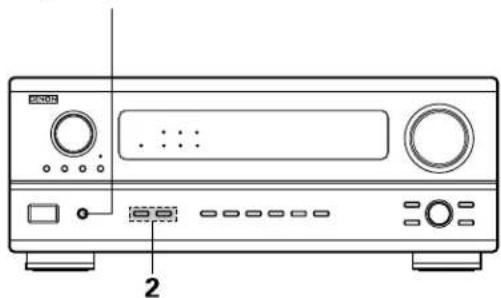
natural_image
Line drawing of a CD-ROM front panel with buttons and ports (no text or symbols)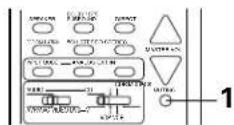
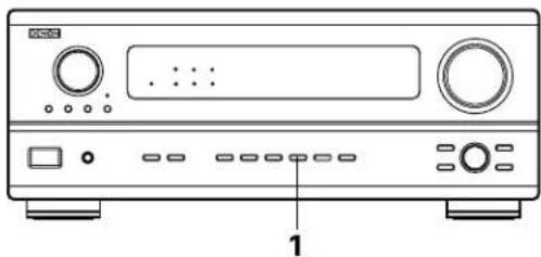
natural_image
Front view diagram of a CD-ROM front panel with buttons and ports (no text or labels)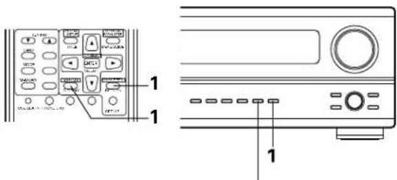
text_image
Diagram showing front and back views of a device control panel with labeled buttons and portsUsing the dimmer function
- Use this to change the brightness of the display. The display brightness changes in four steps (bright, medium, dim and off) by pressing the remote control unit's DIMMER button repeatedly.
* The brightness changes in 3 steps each time the button is pressed, and finally the display turns off.
DIMMER

(Main unit)
Recording using the REC OUT selector
1
Press the REC SELECT button.
REC SELECT

(Main unit)
2
With "REC OUT SOURCE" displayed, turn the FUNCTION knob to select the source you wish to record.
- The "REC" indicator and the indicator of the selected source light.
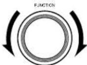
(Main unit)
3
Set the recording mode.
- For operating instructions, refer to the manual of the component on which you want to record.
4
To cancel, turn the function knob and select "SOURCE".
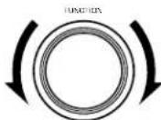
(Main unit)
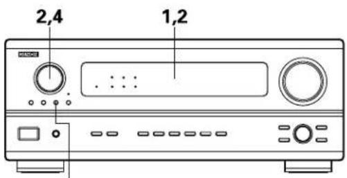
text_image
2,4 1,21,4
Display
2
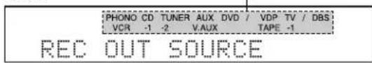
text_image
PHONO CD TUNER AUX DVD / VDP TV / DBS VCR -1 -2 VAUX TAPE -1 REC OUT SOURCENOTES:
• Digital signals are not output from output jacks.
- Only the currently playing source can be recorded to CDR/TAPE.
Playback using the external input (EXT. IN) jacks
1
Set the external input (EXT. IN) mode.
Press the EXT. IN to switch the external input.
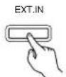

(Main unit) (Remote control unit)
Once this is selected, the input signals connected to the FL (front left), FR (front right) and C (center) channels of the EXT. IN jacks are output directly to the front (left and right) and center speaker systems as well as the pre-out jacks without passing through the surround circuitry.
In addition, the signal input to the SW (subwoofer) jack is output to the PRE OUT SUBWOOFER jack.
2
Cancelling the external input mode
To cancel the external input (EXT. IN) setting, press the INPUT MODE (AUTO, PCM, DTS) or ANALOG button to switch to the desired input mode. (See page 32.)
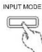
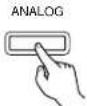
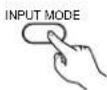

(Main unit) (Remote control unit)
- When the input mode is set to the external input (EXT. IN), the play mode (DIRECT, STEREO, DOLBY/DTS SURROUND, 5CH STEREO or DSP SIMULATION) cannot be set.
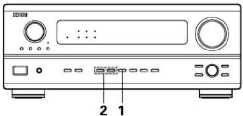
text_image
2 1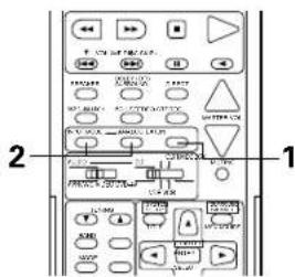
text_image
2 1NOTES:
- In play modes other than the external input mode, the signals connected to these jacks cannot be played. In addition, signals cannot be output from channels not connected to the input jacks.
- The external input mode can be set for any input source. To watch video while listening to sound, select the input source to which the video signal is connected, then set this mode.
10 SURROUND
Before playing with the surround function
- Before playing with the surround function, be sure to use the test tones to adjust the playback level from the different speakers. This adjustment can be performed with the system setup (see page 19) or from the remote control unit, as described below.
- Adjusting with the remote control unit using the test tones is only possible in the "Auto" mode and only effective in the DOLBY SURROUND modes. The adjusted levels for the different modes are automatically stored in the memory.
1 Press the T. TONE button.

(Remote control unit)
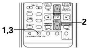
text_image
1,3 22 Test tones are output from the different speakers. Use the channel volume adjust buttons to adjust so that the volume of the test tones is the same for all the speakers.

(Remote control unit)
3 After completing the adjustment, press the T. TONE button again.

(Remate control unit)
• After adjusting using the test tones, adjust the channel levels either according to the playback sources or to suit your tastes, as described below.
1 Select the speaker whose level you want to adjust.

(Main unit)

(Remote control unit)
The channel switches as shown below each time the button is pressed.
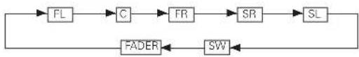
flowchart
graph LR
    A["FL"] --> B["C"]
    B --> C["FR"]
    C --> D["SR"]
    D --> E["SL"]
    E --> F["FADER"]
    F --> G["SW"]
2 Adjust the level of the selected speaker. SELECT
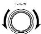
(Main unit)
Only adjustable when the channel is selected with the CH.VOL buttons on the main unit.

(Remote control unit)
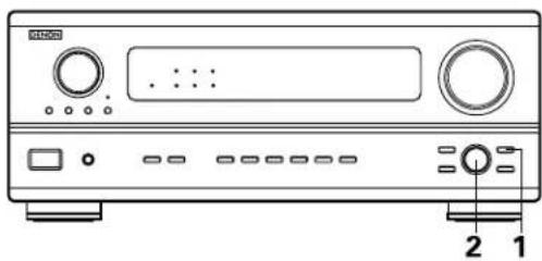
natural_image
Front panel of a portable electronic device with ports, buttons, and a display (no visible text or symbols)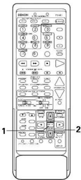
text_image
DENON 1 2 3 4 5 6 7 8 9 10 11 1 2 3 4 5 6 7 8 9 10 11 1 2 3 4 5 6 7 8 9 10 11 1 2 3 4 5 6 7 8 9 10 11 1 2 3 4 5 6 7 8 9 10 11 1 1 2 3 4 5 6 7 8 9 10 1 2 3 4 5 6 7 8 9 10 1 2 3 4 5 6 7 8 9 10 10 10 10 10 10 10 10 10 10 10 10 10 10 10 10 10 10 10 10 10 10 10 10 10 10 10 10 10 10 10 10 10 10NOTES:
- The adjustment range for the different channels is +12 dB to -12 dB.
- When using the DIRECT mode, the sound from the subwoofer can be cut by lowering the SW (subwoofer) setting one step from -12 dB (setting it to "OFF").
Fader function
- This function makes it possible to lower the volume of the front channels (FL, C and FR) or the rear channels (SL and SR) together. Use it for example to adjust the balance of the sound from the different positions when playing multi-channel music sources.
1
Select "FADER".

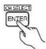
(Main unit) (Remote control unit)
The channel switches in the order shown below each time this button is pressed.
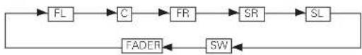
flowchart
graph LR
    A["FL"] --> B["C"]
    B --> C["FR"]
    C --> D["SR"]
    D --> E["SL"]
    E --> F["FADER"]
    F --> G["SW"]
2
Press the button to reduce the volume of the front channels, the button to reduce the volume of the rear channels.
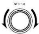
(Main unit) (Remote control unit)
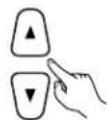
* The channel whose channel level is adjusted lowest can be faded to -12 dB using the fader function.
* If the channel levels are adjusted separately after adjusting the fader, the fader adjustment values are cleared, so adjust the fader again.
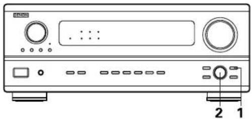
natural_image
Front panel of a CD-ROM device showing front panel, buttons, and control knob (no text or labels visible)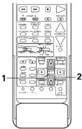
text_image
1 2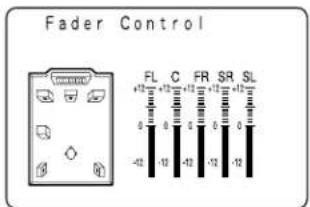
text_image
Fader Control FL C FR SR SL +12 +12 +12 +12 +12 +12 -42 -12 -42 -12 -12This is only displayed when setting the fader control.
Dolby Surround Pro Logic mode
1
Select the Dolby Surround Pro Logic mode.
• The Dolby Pro Logic indicator lights.
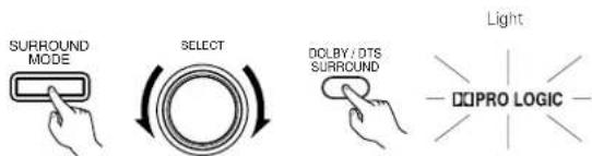
text_image
SURROUND MODE SELECT DOLBY / DTS SURROUND Light DOPRO LOGIC(Main unit) (Remote control unit)
2
Play a program source with the DOLBY SURROUND
- For operating instructions, refer to the manuals of the respective components.
NOTE:
- There are four Dolby Surround Pro Logic modes (NORMAL, PHANTOM, WIDE and 3CH. LOGIC). The AVR-2801/981 sets the mode automatically according to the types of speakers set during the system setup process (page 15).
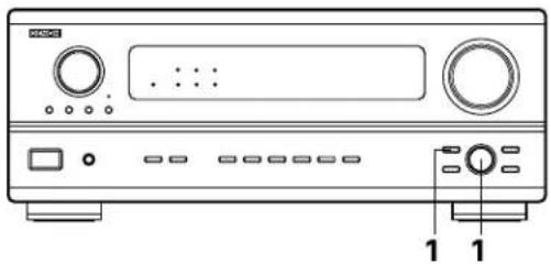
natural_image
Front panel of a CD-ROM device showing front panel, buttons, and control buttons (no text or labels visible)
Dolby Digital mode (only with digital input) and DTS Surround mode (only with digital input)
1
Select the input source.
Playback with a digital input
① Select an input source set to digital (COAXIAL/OPTICAL). (see page 20).
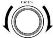
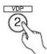
(Main unit) (Remote control unit)
② Set the input mode to "AUTO" or "DTS".
INPUT MODE

INPUT MODE

(Main unit) (Remote control unit)
2
Select the Dolby/DTS Surround mode.

(Remote control unit)
When performing this operation from the main unit's panel, press the SURROUND MODE button, then turn the SELECT knob and select "DOLBY/DTS".
SURROUND

(Main unit)
SELECT

(Main unit)
3
Play a program source with the


- The Dolby Digital indicator lights when playing Dolby Digital sources.
The DTS indicator lights when playing DTS sources.
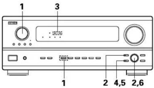
text_image
1 3 1 2 4,5 2,6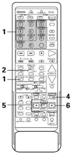
text_image
1 DENON 2 3 4 5 6 7 8 9 10 0 2 4 5 6 3 4 5 6 4 5 6 5 7 8 9 6 7 8 9 7 8 9 8 10 11 9 12 13 14 15 16 17 18 19 20 21 22 23 24 25 26 27 28 29 30 31 30 31 32 33 34 35 34 35 36 35 36 37 36 37 38 37 38 39 38 39 40 40 41 42 43 44 45 46 47 48 47 48 49 48 49 50 50 51 52 53 54 55 56 57 58 59 60 61 62 63 64 65 66 67 68 69 70 71 72 73 74 75 76 77 78 79 79 80 81 82 83 84 85 86 87 88 89 90 91 92 93 94 95 96 97 98 99 1004
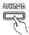
(Main unit)
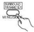
(Remote control unit)
Display the surround parameter menu.
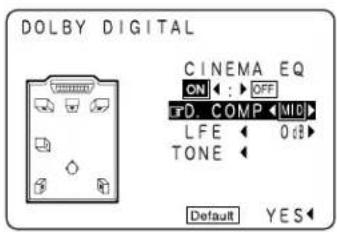
text_image
DOLBY DIGITAL CINEMA EQ ON : OFF T D COMP MID L FE 0 dB TONE Default YES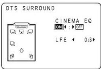
text_image
DTS SURROUND CINEMA EQ ON : OFF LFE 0.48(When displayed with the remote control unit) (When displayed with the buttons on the main unit)
5
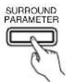
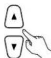
(Remote control unit)(Main unit)
Select the various parameters.
6
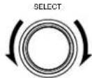

(Remote control unit)(Main unit)
Adjust the parameter settings.
NOTES:
- When "Default" is selected and the cursor button is pressed, "CINEMA EQ." and "D.COMP." are automatically turned off, "LFE" is reset and the tone is set to the default value.
- With this model, Dolby Digital encoded signals can only be played in the Dolby Pro Logic, Dolby Digital, DIRECT and STEREO mode. Other surround mode buttons will not function during the Dolgy Digital signal playback.
- With this mode, DTS signals can only be played in the DTS Surround, DIRECT and STEREO mode. Other surround mode buttons will not function during the DTS signal playback.
Surround parameters 1
CINEMA EQ. (Cinema Equalizer):
The Cinema EQ function gently decreases the level of the extreme high frequencies, compensating for overly-bright sounding motion picture soundtracks. Select this function if the sound from the front speakers is too bright.
This function only works in the Dolby Pro Logic, Dolby Digital and DTS Surround modes.
D.COMP. (Dynamic Range Compression):
Motion picture soundtracks have tremendous dynamic range (the contrast between very soft and very loud sounds). For listening late at night, or whenever the maximum sound level is lower than usual, the Dynamic Range Compression allows you to hear all of the sounds in the soundtrack (but with reduced dynamic range). (This only works when playing program sources recorded in Dolby Digital or DTS.) Select one of the four parameters ("OFF", "LOW", "MID" (middle) or "HI" (high)). Set to OFF for normal listening.
LFE (Low Frequency Effect):
Program source and adjustment range
- Dolby Digital: -10 dB to 0 dB
- DTS Surround: -10 dB to 0 dB
* When DOLBY DIGITAL encoded software is played, it is recommended that the LFE LEVEL be set to 0 dB for correct DOLBY DIGITAL playback.
* When DTS encoded movie software is played, it is recommended that the LFE LEVEL be set to 0 dB for correct DTS playback.
* When DTS encoded music software is played, it is recommended that the LFE LEVEL be set to -10 dB for correct DTS playback.
TONE:
This adjusts the tone control. (See "Surround parameters ②" on page 43 and page 44)
- The AVR-2801/981 is equipped with a high performance DSP (Digital Signal Processor) which uses digital signal processing to synthetically recreate the sound field. One of six preset surround modes can be selected according to the program source and the parameters can be adjusted according to the conditions in the listening room to achieve a more realistic, powerful sound. These surround modes can also be used for program sources not recorded in Dolby Surround Pro Logic or Dolby Digital.
Surround modes and their features
| 1 | ROCK ARENA | Use this mode to achieve the feeling of a live concert in an arena with reflected sounds coming from all directions. |
| 2 | JAZZ CLUB | This mode creates the sound field of a live house with a low ceiling and hard walls. This mode gives jazz a very vivid realism. |
| 3 | VIDEO GAME Use this to enjoy video game sources. | |
| 4 | MATRIX | Select this to emphasize the sense of expansion for music sources recorded in stereo. Signals consisting of the difference component of the input signals (the component that provides the sense of expansion) processed for delay are output from the surround channel. |
| 5 | 5CH STEREO | In this mode, the signals of the front left channel are output from the left surround channel, the signals of the front right channel are output from the right surround channel, and the same (in-phase) component of the left and right channels is output from the center channel. This mode provides all speaker surround sound, but without directional steering effects, and works with any stereo program source. |
| 6 | MONO MOVIE (NOTE 1) | Select this when watching monaural movies for a greater sense of expansion. |
* Depending on the program source being played, the effect may not be very noticeable. In this case, try other surround modes, without worrying about their names, to create a sound field suited to your tastes.
NOTE 1: When playing sources recorded in monaural, the sound will be one-sided if signals are only input to one channel (left or right), so input signals to both channels. If you have a source component with only one audio output (monophonic camcorder, etc.) obtain a "Y" adaptor cable to split the mono output to two outputs, and connect to the L and R inputs.
NOTE:
Only the DIRECT mode can be used when playing PCM signals with a sampling frequency of 96 kHz (such as from DVD-Video discs that contain 24 bit, 96 kHz audio). If such signals are input during playback in one of the other surround modes, the mode automatically switches to DIRECT.
Personal Memory Plus
This set is equipped with a personal memorize function that automatically memorizes the surround modes and input modes selected for the input different sources. When the input source is switched, the modes set for that source last time it was used are automatically recalled.
* The surround parameters, tone control settings and playback level balance for the different output channels are memorized for each surround mode.
DSP surround simulation
- To operate the surround mode and surround parameters from the remote control unit.
1
Select the surround mode for the input channel.
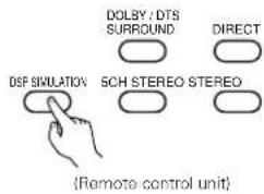
text_image
DOLBY : DTS SURROUND DIRECT DSF SIMULATION SCH STEREO STEREO (Remote control unit)The surround mode switches in the following order each time the DSP SIMULATION button is pressed:
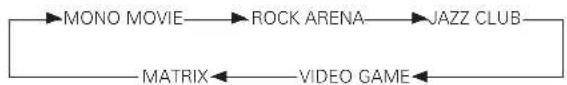
flowchart
graph LR
    A["MONO MOVIE"] --> B["ROCK ARENA"]
    B --> C["JAZZ CLUB"]
    D["MATRIX"] <--_E["VIDEO GAME"]
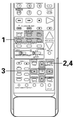
text_image
7 B S 10 0 0.78 1 2,4 32
(Remote control unit)
Display the surround parameter screen on the monitor.
* The screen for the selected surround mode appears.
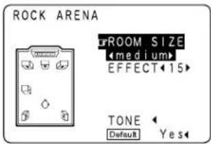
text_image
ROCK ARENA ROOM SIZE Medium EFFECT 15 TONE Default Yes3
(Remote control unit)

Set the parameters.
4
(Remote control unit)
To end the setting mode, press the surround parameter button again.
NOTES:
- When "Default" is selected, "CINEMA EQ." and "D.COMP." are automatically turned off, "ROOM SIZE" is set to "medium", "EFFECT LEVEL" to "10" and "DELAY TIME" to "30ms".
- The "ROOM SIZE" expresses the expansion effect for the different surround modes in terms of the size of the sound field, not the actual size of the listening room.
- Operating the surround mode and surround parameters from the main unit's panel.
1
Turn the SELECT knob to select the surround mode.
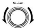
(Main unit)
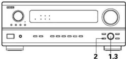
text_image
Diagram of a CD-ROM front panel with labeled buttons and ports- When turned clockwise

flowchart
graph LR
    A["DIRECT"] --> B["STEREO"]
    B --> C["DOLBY PRO LOGIC"]
    C --> D["5CH STEREO"]
    D --> E["MONO MOVIE"]
    F["MATRIX"] <--_G["VIDEO GAME"]
    G --> H["JAZZ CLUB"]
    H --> I["ROCK ARENA"]
- When turned counterclockwise

flowchart
graph LR
    A["DIRECT"] --> B["STEREO"]
    B --> C["DOLBY PRO LOGIC"]
    C --> D["5CH STEREO"]
    D --> E["MONO MOVIE"]
    E --> F["MOBILE"]
    F --> G["VIDEO GAME"]
    G --> H["JAZZ CLUB"]
    H --> I["ROCK ARENA"]
* To select the surround mode while adjusting the surround parameters, channel volume or tone control, press the surround mode button then operate the selector.
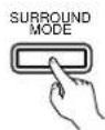
(Main unit)
2
Press the SURROUND PARAMETER button.
Press and hold in the surround parameter button to select the parameter you want to set.
- The parameters which can be set differ for the different surround modes. (Refer to "Surround Modes and Parameters" on page 44.
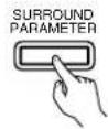
(Main unit)
3
Display the parameter you want to adjust, then turn the SELECT knob to set it.
NOTE:
- When playing PCM digital signals or analog signals in the 5CH STEREO, ROCK, ARENA, JAZZ CLUB, VIDEO GAME, MONO MOVIE or MATRIX surround modes and the input signal switches to a digital signal encoded in Dolby Digital, the Dolby surround mode switches automatically. When the input signal switches to a DTS signal, the mode automatically switches to DTS surround.
Tone control setting
- Use the tone control setting to adjust the bass and treble as desired.
• To operate the tone control from the remote control unit.
1
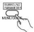
(Remote control unit)
Display the surround parameter screen on the monitor.
* The screen for the selected surround mode appears. "TONE" cannot be selected in the Direct mode.
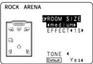
text_image
ROCK ARENA ROOM SIZE Medium EFFECT 15 TONE Default Yes2
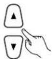
(Remote control unit)
Select "TONE".
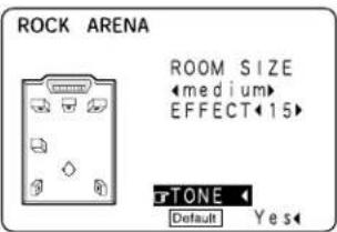
text_image
ROCK ARENA ROOM SIZE Medium EFFECT 15 TONE Default Yes3

(Remote control unit)
Switch to the Tone Control screen.
Tone Control
Bass -6dB Treble +10dB
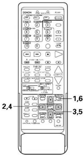

(Remote control unit)
- To set the level.

* If you do not want the tone to be adjusted, set "Tone Defeat" to "ON".

5

(Remote control unit)
Enter the setting.
The surround menu screen re-appears.
6
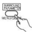
(Remote control unit)
To end the setting mode, press the surround parameter button again.
• To operate the tone control from the main unit.
1
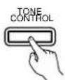
(Main unit)
The tone switches as follows each time the TONE CONTROL button is pressed.
BASS ←→ TREBLE
2
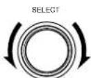
(Main ulni)
With the name of the volume to be adjusted selected, turn the SELECT knob to adjust the level.
• To increase the bass or treble:
Turn the control clockwise. (The bass or treble sound can be increased to up to +12 dB in steps of 2 dB.)
• To decrease the bass or treble:
Turn the control clockwise. (The bass or treble sound can be decreased up to -12 dB in steps of 2 dB.)
Surround parameters ②
ROOM SIZE:
This sets the size of the sound field.
There are five settings: "small", "med.s" (medium-small), "medium", "med.l" (medium-large) and "large". "small" recreates a small sound field, "large" a large sound field.
EFFECT LEVEL:
This sets the strength of the surround effect.
The level can be set in 15 steps from 1 to 15. Lower the level if the sound seems distorted.
DELAY TIME:
In the matrix mode only, the delay time can be set within the range of 0 to 140 ms.
TONE CONTROL:
This can be set individually for the separate surround modes other than Direct.
■ Surround modes and parameters
| Signals and adjustability in the different modes | |||||||||||
| Mode | Channel output Parameter (default values are shown in parentheses) | ||||||||||
| SURROUN L/R | SUB- WOOFER | TONE CONTROL | CINEMA EQ. | ROOM SIZE | EFFECT LEVEL | DELAY TIME | When playing Dolby Digital/DTS signals | ||||
| D. COMP L | FEFRONT L/F | ||||||||||
| DIRECT | ○ | × | × | ◎ | × | × | × | × | × | ○ (OFF) | ○ (0dB) |
| STEREO | ○ | × | × | ◎ | ○ (0dB) | × | × | × | × | ○ (OFF) | ○ (0dB) |
| 6CH EXTERNAL INPUT | ○ | ◎ | ◎ | ◎ | ○ (0dB) | × | × | × | × | × | × |
| DOLBY PRO LOGIC | ○ | ◎ | ◎ | ◎ | ○ (0dB) | ○ (OFF) | × | × | × | ○ (OFF) | ○ (0dB) |
| DOLBY DIGITAL | ○ | ◎ | ◎ | ◎ | ○ (0dB) | ○ (OFF) | × | × | × | ○ (OFF) | ○ (0dB) |
| DTS SURROUND | ○ | ◎ | ◎ | ◎ | ○ (0dB) | ○ (OFF) | × | × | × | ○ (OFF) | ○ (0dB) |
| 5CH STEREO | ○ | ◎ | ◎ | ◎ | ○ (0dB) | × | × | × | × | × | × |
| ROCK ARENA | ○ | ◎ | ◎ | ◎ | ○ (0dB) | × | ○ (Medium) | ○ (10) | × | × | × |
| JAZZ CLUB | ○ | ◎ | ◎ | ◎ | ○ (0dB) | × | ○ (Medium) | ○ (10) | × | × | × |
| VIDEO GAME | ○ | ◎ | ◎ | ◎ | ○ (0dB) | × | ○ (Medium) | ○ (10) | × | × | × |
| MONO MOVIE | ○ | ◎ | ◎ | ◎ | ○ (0dB) | × | ○ (Medium) | ○ (10) | × | × | × |
| MATRIX | ○ | ◎ | ◎ | ◎ | ○ (0dB) | × | × | × | ○ (30msec) | × | × |
○ : Signal/adjustable
©: Turned on or off by speaker configuration setting
△ : Selected by speaker configuration setting
×; No signal/not adjustable
12 LISTENING TO THE RADIO
Auto tuning
1
Set the input function to "TUNER".
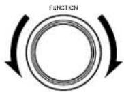
(Main unit) (Remote control unit)

2
Watching the display, press the BAND button to select the desired band (AM or FM).

(Remote control unit)
3
Press the MODE button to set the auto tuning mode.

(Remote control unit)
"Auto" appears on the display.
4
Press the TUNING UP or DOWN button.
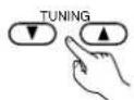
(Remote control unit)
Automatic searching begins, then stops when a station is tuned in.
If tuning does not stop at the desired station, use to the "Manual tuning" operation.
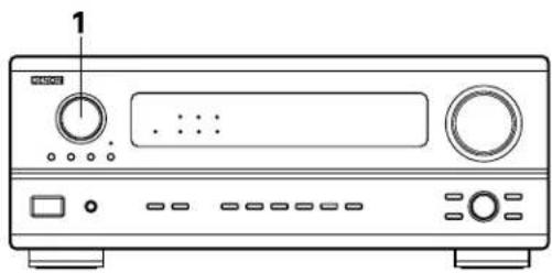
natural_image
Line drawing of a CD-ROM front panel with control knobs and buttons (no text or symbols)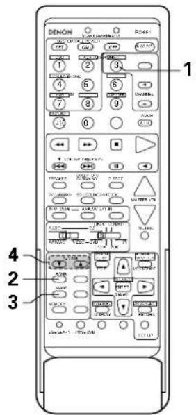
text_image
1 2 3 4 5 6 7 8 9 10 11 12 13 14 15 16 17 18 19 20 21 22 23 24 25 26 27 28 29 30 31 32 33 34 35 36 37 38 39 40 41 42 43 44 45 46 47 48 49 50 51 52 53 54 55 56 57 58 59 60 61 62 63 64 65 66 67 68 69 70 71 72 73 74 75 76 77 78 79 80 81 82 83 84 85 86 87 88 89 90Manual tuning
1
Set the input function to "TUNER".
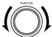
(Main unit) (Remote control unit)
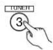
2
Watching the display, press the BAND button to select the desired band (AM or FM).

(Remote control unit)
3
Press the MODE button to set the manual tuning mode. Check that the display's "AUTO" indicator turns off.

(Remote control unit)
4
Press the TUNING UP or DOWN button to tune in the desired station.
The frequency changes continuously when the button is held in.
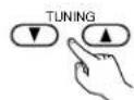
(Remote control unit)
NOTES:
- When in the auto tuning mode on the FM band, the "STEREO" indicator lights on the display when a stereo broadcast is tuned in. At open frequencies, the noise is muted and the "TUNED" and "STEREO" indicators turn off.
- When the manual tuning mode is set, FM stereo broadcasts are received in monaural and the "STEREO" indicator turns off.
Preset memory
1 Use the "Auto tuning" or "Manual tuning" operation to tune in the station to be preset in the memory.
2 Press the MEMORY button.

(Remote control unit)
3 Press the SHIFT button and select the desired memory block (A to E).

(Remote control unit)
4 Press the PRESET UP or DOWN button to select the desired preset channel (1 to 8).
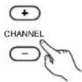
(Remote control unit)
5 Press the MEMORY button again to store the station in the preset memory.

(Remote control unit)
To preset other channels, repeat steps 2 to 5. A total of 40 broadcast stations can be preset — 8 stations (channels 1 to 8) in each of blocks A to E.
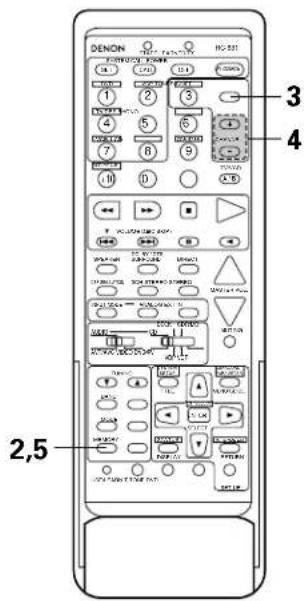
text_image
DENON 3 4 2,5Checking the preset stations
- The preset broadcast stations can be checked on the on screen display.
1 Press the ON SCREEN button repeatedly until the "Tuner Preset Stations" screen appears on the on screen display.

(Remote control unit)
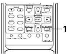
text_image
TUNION RIGHT RIGHT RIGHT RIGHT RIGHT RIGHT RIGHT RIGHT RIGHT RIGHT RIGHT RIGHT RIGHT RIGHT RIGHT RIGHT RIGHT RIGHT RIGHT RIGHT RIGHT RIGHT RIGHT RIGHT RIGHT RIGHT RIGHT RIGHT RIGHT RIGHT RIGHT RIGHT RIGHT RIGHT RIGHT RIGHT RIGHT RIGHT RIGHT RIGHT RIGHT RIGHT RIGHT RIGHT RIGHT RIGHT RIGHT RIGHT RIGHT RIGHT Right Right Right Right Right Right Right Right Right Right Right Right Right Right Right Right Right Right Right Right Right Right Right Right Right Right Right Right Right Right Right Right Right Right Right RightTuner Preset Stations
A1FM 87.50MHz
A2FM 89.10MHz
A3FN 98,10MHz
A4FM107.90MHz
A5FM 90.10MHz
A6FM 90.10MHz
A7FM 90.10MHz
A8FM 90.10MHz
Recalling preset stations
• To call out out preset stations from the remote control unit.
1

(Remote control unit)
Watching the display, press the SHIFT button to select the preset memory block.
2
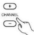
(Remote control unit)
Watching the display, press the PRESET UP or DOWN button to select the desired preset channel.
- Calling out preset stations from the main unit's panel.
1


(Main unit)
Press the TUNING PRESET button.
2
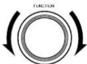
(Main unit)
Turn the FUNCTION knob and select the desired station.
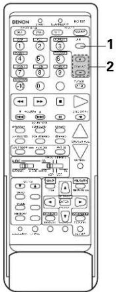
text_image
1 2 DENDON LANTAL HOLD 1 2 3 4 5 6 7 8 9 10 11 12 13 14 15 16 17 18 19 20 21 22 23 24 25 26 27 28 29 30 31 32 33 34 35 36 37 38 39 40 41 42 43 44 45 46 47 48 49 50 51 52 53 54 55 56 57 58 59 60 61 62 63 64 65 66 67 68 69 70 71 72 73 74 75 76 77 78 79 80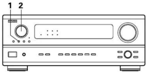
text_image
1 213 LAST FUNCTION MEMORY
- This unit is equipped with a last function memory which stores the input and output setting conditions as they were immediately before the power is switched off.
This function eliminates the need to perform complicated resettings when the power is switched on. - The unit is also equipped with a back-up memory. This function provides approximately one week of memory storage when the main unit's power switch is off and with the power cord disconnected.
14 INITIALIZATION OF THE MICROPROCESSOR
When the indication of the display is not normal or when the operation of the unit does not show the reasonable result, the initialization of the microprocessor is required by the following procedure.
1
Switch off the unit and remove the AC cord from the wall outlet.
2
Hold the following A button and B button, and plug the AC cord into the outlet.
3
Check that the entire display is flashing with an interval of about 1 second, and release your fingers from the 2 buttons and the microprocessor will be initialized.
NOTES:
- If step 3 does not work, start over from step 1.
- If the microprocessor has been reset, all the button settings are reset to the default values (the values set upon shipment from the factory).
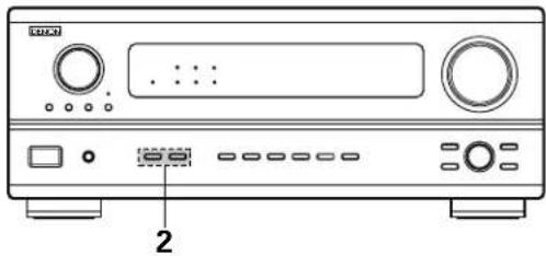
natural_image
Front view of a CD-ROM computer front panel with ports and buttons (no visible text or labels)15 TROUBLESHOOTING
If a problem should arise, first check the following.
-
Are the connections correct?
-
Have you operated the receiver according to the Operating Instructions?
-
Are the speakers, turntable and other components operating property?
If this unit is not operating properly, check the items listed in the table below. Should the problem persist, there may be a malfunction.
Disconnect the power immediately and contact your store of purchase.
| Symptom Cause Measures | Page | |||
| Common problems when listening to the CD, records, tapes and FM broadcasts, etc. | DISPLAY not lit and sound not produced when power switch set to on. | Power cord not plugged in securely. | Check the insertion of the power cord plug.Turn the power on with the remote control unit after turning the POWER switch on. | 631 |
| DISPLAY lit but sound not produced. | Speaker cords not securely connected.Improper position of the audio function button.Volume control set to minimum.MUTING is on.Digital signals not input Digital input selected. | Connect securely.Set to a suitable position.Turn volume up to suitable level.Switch off MUTING.Input digital signals or select input jacks to which digital signals are being input. | 10, 1132333432 | |
| DISPLAY not lit and power indicator is flashing rapidly. | Speaker terminals are short-circuited.Block the ventilation holes of the set.The unit is operating at continuous high power conditions and/or inadequate ventilation. | Switch power off, connect speakers properly, then switch power back on.Turn off the set's power, then ventilate it well to cool it down.Once the set is cooled down, turn the power back on.Turn off the set's power, then ventilate it well to cool it down.Once the set is cooled down, turn the power back on. | 10, 114, 54, 5 | |
| Sound produced only from one channel. | Incomplete connection of speaker cords.Incomplete connection of input/output cords. | Connect securely.Connect securely. | 10, 116 ~ 11 | |
| Positions of instruments reversed during stereo playback. | Reverse connections of left and right speakers or left and right input/output cords. | Check left and right connections. 10, 11 | ||
| The on screen display is not displayed. | "On screen display" is set to off on the system setup menu screen. | Set "on screen display" on the system setup menu screen to on. | 22 | |
| When playing records | Humming noise produced when record is playing. | Ground wire of turntable not connected properly.Incomplete PHONO jack connection.TV or radio transmission antenna nearby. | Connect securely.Connect securely.Contact your store of purchase. | 66— |
| Howling noise produced when volume is high. | Turntable and speaker systems too close together.Floor is unstable and vibrates easily. | Separate as much as possible.Use cushions to absorb speaker vibrations transmitted by floor. If turntable is not equipped with insulators, use audio insulators (commonly available). | —— | |
| Sound is distorted. | Stylus pressure too weak.Dust or dirt on stylus.Cartridge defective. | Apply proper stylus pressure.Check stylus.Replace cartridge. | ——— | |
| Volume is weak. | MC cartridge being used. | Replace with MM cartridge or use a head amplifier or step-up transformer. | 6 | |
| Remote control unit | This unit does not operate properly when remote control unit is used. | Batteries dead.Remote control unit too far from this unit.Obstacle between this unit and remote control unit.Different button is being pressed.⊕ and⊖ ends of battery inserted in reverse. | Replace with new batteries.Move closer.Remove obstacle.Press the proper button.Insert batteries properly. | 232323—23 |
16 ADDITIONAL INFORMATION
Speaker setting examples
Here we describe a number of speaker settings for different purposes. Use these examples as guides to set up your system according to the type of speakers used and the main usage purpose.
(1) Basic setting
Use this setting if your main purpose is to listen to movie music and when using one set (two speakers) of regular single-way or two-way speakers as the surround speakers.
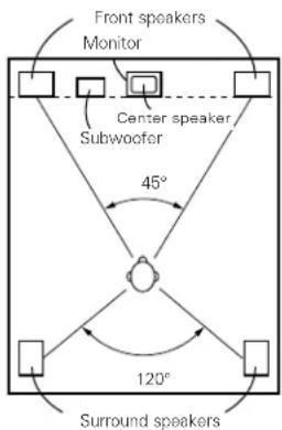
text_image
Front speakers Monitor Center speaker, Subwoofer 45° 120° Surround speakersAs seen from above
- Set the front speakers with their front surfaces as flush with the TV or monitor screen as possible. Set the center speaker between the front left and right speakers and no further from the listening position than the front speakers.
- Consult the owner's manual for your subwoofer for advice on placing the subwoofer within the listening room.
- If the surround speakers are direct-radiating (monopolar) then place them slightly behind and at an angle to the listening position and parallel to the walls at a position 60 to 90 centimeters (2 to 3 feet) above ear level at the prime listening position.
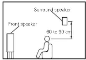
text_image
Front speaker Surround speaker 60 to 90 cmAs seen from the side
(2) Using diffusion type speakers for the surround speakers
For the greatest sense of surround sound envelopment, diffuse radiation speakers such as bipolar types, or dipolar types, provide a wider dispersion than is possible to obtain from a direct radiating speaker (monopolar). Place these speakers at either side of the prime listening position, mounted above ear level.
Path of the surround sound from the speakers to the listening position
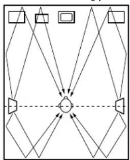
flowchart
graph TD
    A[" "] --> B[" "]
    C[" "] --> B[" "]
    D[" "] --> B[" "]
    E[" "] --> B[" "]
    F[" "] --> B[" "]
    G[" "] --> B[" "]
    H[" "] --> B[" "]
    I[" "] --> B[" "]
    J[" "] --> B[" "]
    K[" "] --> B[" "]
    L[" "] --> B[" "]
    M[" "] --> B[" "]
    N[" "] --> B[" "]
    O[" "] --> B[" "]
    P[" "] --> B[" "]
    Q[" "] --> B[" "]
    R[" "] --> B[" "]
    S[" "] --> B[" "]
    T[" "] --> B[" "]
    U[" "] --> B[" "]
    V[" "] --> B[" "]
    W[" "] --> B[" "]
    X[" "] --> B[" "]
    Y[" "] --> B[" "]
    Z[" "] --> B[" "]
    AA[" "] --> B[" "]
    AB[" "] --> B[" "]
    AC[" "] --> B[" "]
    AD[" "] --> B[" "]
    AE[" "] --> B[" "]
    AF[" "] --> B[" "]
    AG[" "] --> B[" "]
    AH[" "] --> B[" "]
    AI[" "] --> B[" "]
    AJ[" "] --> B[" "]
    AK[" "] --> B[" "]
    AL[" "] --> B[" "]
    AM[" "] --> B[" "]
    AN[" "] --> B[" "]
    AO[" "] --> B[" "]
    AP[" "] --> B[" "]
    AQ[" "] --> B[" "]
    AR[" "] --> B[" "]
    AS[" "] --> B[" "]
    AT[" "] --> B[" "]
    AU[" "] --> B[" "]
    AV[" "] --> B[" "]
    AW[" "] --> B[" "]
    AX[" "] --> B[" "]
    AY[" "] --> B
    AZ[" "] --> B
    BA[" "] --> B
    BB[" "] --> B
    BC[" "] --> B
    BD[" "] --> B
    BE[" "] --> B
    BF[" "] --> B
    BG[" "] --> B
    BH[" "] --> B
    BI[" "] --> B
    BJ[" "] --> B
    BK[" "] --> B
    BL[" "] --> B
    BM[" "] --> B
    BN[" "] --> B
    BO[" "] --> B
    BP[" "] --> B
    BPB[" "] --> BA
    BA --> BB
    BB --> BK
    BK --> BO
    BK --> BP
    BK --> BA
    BK --> BB
    BK --> BO
    BK --> BP
    BK --> BB
    BK --> BO
    BK --> BP
    BK --> BB
    BK --> BO
    BK --> BP
    BK --> BB
    BK --> BO
    BK --> BP
    BK --> BB
    BK --> BO
    BK --> BP
    BK --> BB
    BK --> BO
    BK --> BP
    BK --> BB
    BK --> BO
    BK --> BP
    BK --> BB
    BK --> Bo
    BK --> BP
    BK --> BB
    BK --> BO
    BK --> BP
    BK --> BB
    BK --> BO
    BK --> BP
    BK --> BB
    BK --> BO
    BK --> BP
    BK --> BB
    BK --> BO
    BK --> BP
    BK --> BB
    BK --> BO
    BK --> BP
    BK --> BB
    BK --> BO
    BK --> BP
    BK --> BP
    BK --> BP
    BK --> BP
    BK --> BP
    BK --> BP
    BK --> BP
    BK --> BP
    BK --> BP
    BK --> BP
    BK --> BP
    BK --> BP
    BK --> BP
    BK --> BP
    BK --> BP
    BK --> BP
    BK --> BP
    BK --> BP
    BK --> BP
    BK --> BP
    BK --> BO
As seen from above
- Set the front speakers, center speaker and subwoofer in the same positions as in example (1).
- Set the surround speakers directly at the sides of the listening position and 60 to 90 centimeters (2 to 3 feet) above ear level.
- The signals from the surround channels reflect off the walls as shown on the diagram at the left, creating an enveloping and realistic surround sound presentation.
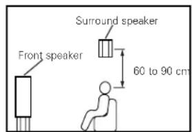
text_image
Front speaker Surround speaker 60 to 90 cmAs seen from the side
Surround
The AVR-2801/981 is equipped with a digital signal processing circuit that lets you play program sources in the surround mode to achieve the same sense of presence as in a movie theater.
Dolby Surround
(1) Dolby Digital (Dolby Surround AC-3)
Dolby Digital is the multi-channel digital signal format developed by Dolby Laboratories.
Dolby Digital consists of up to "5.1" channels - front left, front right, center, surround left, surround right, and an additional channel exclusively reserved for additional deep bass sound effects (the Low Frequency Effects - LFE - channel, also called the ".1" channel, containing bass frequencies of up to 120 Hz).
Unlike the analog Dolby Pro Logic format, Dolby Digital's main channels can all contain full range sound information, from the lowest bass, up to the highest frequencies – 22 kHz. The signals within each channel are distinct from the others, allowing pinpoint sound imaging, and Dolby Digital offers tremendous dynamic range from the most powerful sound effects to the quietest, softest sounds, free from noise and distortion.
■ Dolby Digital and Dolby Pro Logic
| Comparison of home surround systems Dolby Digital Dolby Pro Logic | ||
| No. recorded channels (elements) 5.1 ch 2 ch | ||
| No. playback channels 5.1 ch 4 ch | ||
| Playback channels (max.) L, R, C, SL, SR, SW L, R, C, S (SW - recommended) | ||
| Audio processing | Digital discrete processingDolby Digital (AC-3) encoding/decoding | Analog matrix processing Dolby Surround |
| High frequency playback limit of surround channel | 20 kHz 7 kHz | |
■ Dolby Digital compatible media and playback methods
Marks indicating Dolby Digital compatibility:


The following are general examples. Also refer to the player's operating instructions.
| Media Dolby Digital output | jacks Playback method (reference page) | |
| LD {VDP} | Coaxial Dolby Digital RF output jack *1 | Set the input mode to “AUTO”. (Page 32) |
| DVD | Optical or coaxial digital output (same as for PCM) *2 | Set the input mode to “AUTO”. (Page 32) |
| Others (satellite broadcasts, CATV, etc.) | Optical or coaxial digital output (same as for PCM) | Set the input mode to “AUTO”. (Page 32) |
*1 Please use a commercially available adapter when connecting the Dolby Digital RF (AC-3RF) output jack of the LD player to the digital input jack.
Please refer to the instruction manual of the adapter when making connection.
*2 Some DVD digital outputs have the function of switching the Dolby Digital signal output method between "bit stream" and "(convert to) PCM". When playing in Dolby Digital surround on the AVR-2801/981, switch the DVD player's output mode to "bit stream". In some cases players are equipped with both "bit stream + PCM" and "PCM only" digital outputs. In this case connect the "bit stream + PCM" jacks to the AVR-2801/981.
(2) Dolby Pro Logic
Dolby Pro Logic is a multi-channel signal playback system developed by Dolby Laboratories which decodes sources recorded in Dolby Surround into four channels: front left, center, front right and surround (the surround channel is monaural, but is played through two surround speakers). Here, "sources recorded in Dolby Surround" are sources on which surround signals (three channels or more) are recorded onto two channels using Dolby Surround encoding technology. Dolby Surround recording is possible for all two-channel signal sources, including soundtracks on DVDs (*), LDs or hi-fi VCRs (for which stereo signal recording is possible), stereo FM, TV and satellite broadcasts, stereo CD, MD and analog cassette tape recordings. Sources recorded in Dolby Surround are compatible with stereo playback, so they can be played in stereo on regular stereo equipment and in surround with Dolby Pro Logic processing. (DTS and Dolby Digital require special decoders to be played.)
With Dolby Pro Logic, the signal levels of the different channels of the source recorded in Dolby Surround are monitored, channels with higher signal levels are emphasized and the level of the other channels is decreased in order to reinforce the directivity and achieve an effective surround sound.
* DVDs recorded in Dolby Surround include sources recorded in PCM and sources recorded in 2-channel Dolby Digital. For 2-channel Dolby Digital DVD sources, the DVD player's audio mode is 2-channel Dolby Digital, and the AVR-2801/981's surround mode is Dolby Pro Logic.
■ Dolby Pro Logic compatible media and playback methods
Mark indicating Dolby Pro Logic compatibility:

When playing in Dolby Pro Logic, select the input signal according to how the player is connected to the AVR-2801/981, in the same way as selecting the stereo signal (see page 20). Set the surround mode to "DOLBY SURROUND" (see page 37) to play in Dolby Pro Logic.
Manufactured under license from Dolby Laboratories.
"Dolby", "Pro Logic" and the double-D symbol are trademarks of Dolby Laboratories.
Confidential Unpublished Works, ©1992-1997 Dolby Laboratories. All rights reserved.
DTS Digital Surround
Digital Theater Surround (also called simply DTS) is a multi-channel digital signal format developed by Digital Theater Systems.
DTS offers the same "5.1" playback channels as Dolby Digital (front left, front right and center, surround left and surround right) as well as the stereo 2-channel mode. The signals for the different channels are fully independent, eliminating the risk of deterioration of sound quality due to interference between signals, crosstalk, etc.
DTS features a relatively higher bit rate as compared to Dolby Digital (1234 kbps for CDs and LDs, 1536 kbps for DVDs) so it operates with a relatively low compression rate. Because of this the amount of data is great, and when DTS playback is used in movie theaters, a separate CD-ROM synchronized with the film is played.
With LDs and DVDs, there is of course no need for an extra disc; the pictures and sound can be recorded simultaneously on the same disc, so the discs can be handled in the same way as discs with other formats.
There are also music CDs recorded in DTS. These CDs include 5.1-channel surround signals (compared to two channels on current CDs). They do not include picture data, but they offer surround playback on CD players that are equipped with digital outputs (PCM type digital output required).
DTS surround track playback offers the same intricate, grand sound as in a movie theater, right in your own listening room.
■ DTS compatible media and playback methods
Marks indicating DTS compatibility:


The following are general examples. Also refer to the player's operating instructions.
| Media Dolby Digital output | jacks Playback method (reference page) | |
| CD | Optical or coaxial digital output(same as for PCM) *2 | Set the input mode to “AUTO” or “DTS” (page 37).Never set the mode to “ANALOG” or “PCM”. *1 |
| LD (VDP) | Optical or coaxial digital output(same as for PCM) *2 | Set the input mode to “AUTO” or “DTS” (page 37).Never set the mode to “ANALOG” or “PCM”. *1 |
| DVD | Optical or coaxial digital output(same as for PCM) *3 | Set the input mode to “AUTO” or “DTS” (page 37). |
*1 DTS signals are recorded in the same way on CDs and LDs as PCM signals. Because of this, the un-decoded DTS signals are output as random "hissy" noise from the CD or LD player's analog outputs. If this noise is played with the amplifier set at a very high volume, it may possibly cause damage to the speakers. To avoid this, be sure to switch the input mode to "AUTO" or "DTS" before playing CDs or LDs recorded in DTS. Also, never switch the input mode to "ANALOG" or "PCM" during playback. The same holds true when playing CDs or LDs on a DVD player or LD/DVD compatible player. For DVDs, the DTS signals are recorded in a special way so this problem does not occur.
*2 The signals provided at the digital outputs of a CD or LD player may undergo some sort of internal signal processing (output level adjustment, sampling frequency conversion, etc.). In this case the DTS-encoded signals may be processed erroneously, in which case they cannot be decoded by the AVR-2801/981, or may only produce noise. Before playing DTS signals for the first time, turn down the master volume to a low level, start playing the DTS disc, then check whether the DTS indicator on the AVR-2801/981 (see page 38) lights before turning up the master volume.
*3 A DVD player with DTS-compatible digital output is required to play DTS DVDs. A DTS Digital Output logo is featured on the front panel of compatible DVD players. Recent DENON DVD player models feature DTS-compatible digital output – consult the player's owner's manual for information on configuring the digital output for DTS playback of DTS-encoded DVDs.
Manufactured under license from Digital Theater Systems, Inc. US Pat. No. 5,451,942 and other worldwide patents issues and pending. "DTS" and "DTS Digital Surround" are trademarks of Digital Theater Systems, Inc. ©1996 Digital Theater Systems, Inc. All rights reserved.
System setup items and default values (set upon shipment from the factory)
| System setup Default settings | |||||||||||||
| 1 | Speaker Configuration | Input the combination of speakers in your system and their corresponding sizes (SMALL for regular speakers, LARGE for full-size, full-rangel to automatically set the composition of the signals output from the speakers and the frequency response. | Front Sp. Center Sp. | Surround Sp. Subwoofer | |||||||||
| Small | Small YesLarge | ||||||||||||
| Subwoofer mode | This selects the subwoofer speaker for playing deep bass signals. | LFE | |||||||||||
| 2 | Delay Time | This parameter is for optimizing the timing with which the audio signals are produced from the speakers and subwoofer according to the listening position. | Front & Subwoofer | Center | Surround L & R — | ||||||||
| 3.6 m (12 ft) | 3.6 m (12 ft) | 3.0 m (10 ft) — | |||||||||||
| 3 | Channel Level | This adjusts the volume of the signals output from the speakers and subwoofer for the different channels in order to obtain optimum effects. | Front L | Front R | Subwoofer | Center | Surround L | Surround R | — | — | |||
| 0 dB | 0 dB | 0 dB | 0 dB | 0 dB | 0 dB | — | — | ||||||
| 4 | Digital In Adjustment | This assigns the digital input jacks for the different input sources. | Input source | CD | DVD | VDP | TV/DBS | VCR-1 | VCR-2/V.AUX | — | — | ||
| Digital Inputs | COAXIAL | OPTICAL 1 | OPTICAL 2 | OPTICAL 3 | OFF | OFF | — | — | |||||
| 5 | On Screen Display | This sets whether or not to display the on-screen display that appears on the monitor screen when the controls on the remote control unit or main unit are operated (from MONITOR outputs only). | On Screen Display = ON | ||||||||||
| 6 | Auto Tuner Presets | FM stations are received automatically and stored in the memory. | A1 ~ A8 | 87.5/89.1/98.1/107.9/90.1/90.1/90.1/90.1 MHz | |||||||||
| B1 ~ B8 | 520/600/1000/1400/1500/1710 kHz/90.1/90.1 MHz | ||||||||||||
| C1 ~ C8 | 90.1 MHz | ||||||||||||
| D1 ~ D8 | 90.1 MHz | ||||||||||||
| E1 ~ E8 | 90.1 MHz | ||||||||||||
Surround modes and parameters
| Signals and adjustability in the different modes | |||||||||||
| Mode | Channel output Parameter (default values are shown in parentheses) | ||||||||||
| SURROUN L/R | SUB- WOOFER | TONE CONTROL | CINEMA EQ. | ROOM SIZE | EFFECT LEVEL | DELAY TIME | When playing Dolby Digital/DTS signals | ||||
| D. COMP L | FEFRONT L/R CENTER | ||||||||||
| DIRECT | ○ | × | × | ◎ | × | × | × | × | × | ○ (OFF) | ○ (0dB) |
| STEREO | ○ | × | × | ◎ | ○ (0dB) | × | × | × | × | ○ (OFF) | ○ (0dB) |
| 6CH EXTERNAL INPUT | ○ | ◎ | ◎ | ◎ | ○ (0dB) | × | × | × | × | × | × |
| DOLBY PRO LOGIC | ○ | ◎ | ◎ | ◎ | ○ (0dB) | ○ (OFF) | × | × | × | ○ (OFF) | ○ (0dB) |
| DOLBY DIGITAL | ○ | ◎ | ◎ | ◎ | ○ (0dB) | ○ (OFF) | × | × | × | ○ (OFF) | ○ (0dB) |
| DTS SURROUND | ○ | ◎ | ◎ | ◎ | ○ (0dB) | ○ (OFF) | × | × | × | ○ (OFF) | ○ (0dB) |
| 5CH STEREO | ○ | ◎ | ◎ | ◎ | ○ (0dB) | × | × | × | × | × | × |
| ROCK ARENA | ○ | ◎ | ◎ | ◎ | ○ (0dB) | × | ○ (Medium) | ○ (10) | × | × | × |
| JAZZ CLUB | ○ | ◎ | ◎ | ◎ | ○ (0dB) | × | ○ (Medium) | ○ (10) | × | × | × |
| VIDEO GAME | ○ | ◎ | ◎ | ◎ | ○ (0dB) | × | ○ (Medium) | ○ (10) | × | × | × |
| MONO MOVIE | ○ | ◎ | ◎ | ◎ | ○ (0dB) | × | ○ (Medium) | ○ (10) | × | × | × |
| MATRIX | ○ | ◎ | ◎ | ◎ | ○ (0dB) | × | × | × | ○ (30msec) | × | × |
○ : Signal/adjustable
© : Turned on or off by speaker configuration setting
△ : Selected by speaker configuration setting
×: No signal/not adjustable
17 SPECIFICATIONS
■ Audio section
• Power amplifier
Rated output:
Front: 90 W + 90 W (8 Ω/ohms, 20 Hz \~ 20 kHz with 0.05% T.H.D.) 135 W + 135 W (6 Ω/ohms, 1 kHz with 0.7% T.H.D.)
Center: 90 W (8 Ω/ohms, 20 Hz \~ 20 kHz with 0.05% T.H.D.)
135 W (6 Ω/ohms, 1 kHz with 0.7% T.H.D.)
Surround: 90 W + 90 W (8 Ω/ohms, 20 Hz \~ 20 kHz with 0.05% T.H.D.) 135 W + 135 W (6 Ω/ohms, 1 kHz with 0.7% T.H.D.)
Dynamic power:
120 W × 2 ch (8 Ω/ohms)
170 W x 2 ch (4 Ω/ohms)
200 W x 2 ch (2 Ω/ohms)
Output terminals:
Front: A or B 6 \~ 16 Ω/ohms
A + B 8 \~ 16 Ω/ohms
Surround / Center: 6 \~ 16 Ω/ohms
- Analog
Input sensitivity / input impedance:
200 mV / 47 kΩ/kohms
Frequency response:
10 Hz \~ 100 kHz: +0, -3 dB (DIRECT mode)
S/N:
102 dB (DIRECT mode)
Distortion:
0.008% (20 Hz \~ 20 kHz) (DIRECT mode)
Rated output: 1.2 V
- Digital
D/A output:
Rated output — 2 V (at 0 dB playback)
Total harmonic distortion — 0.008% (1 kHz, at 0 dB)
S/N ratio — 102 dB
Dynamic range — 96 dB
Format — Digital audio interface
Digital input:
- Phono equalizer (PHONO input — REC OUT)
Input sensitivity:
2.5 mV
RIAA deviation:
±1 dB (20 Hz to 20 kHz)
Signal-to-noise ratio:
74 dB (A weighting, with 5 mV input)
Rated output / Maximum output:
150 mV / 7 V
Distortion factor:
0.03% (1 kHz, 3 V)
■ Video section
- Standard video jacks
Input / output level and impedance:
1 Vp-p, 75 Ω/ohms
Frequency response:
5 Hz \~ 10 MHz — +0, -3 dB
- S-video jacks
Input / output level and impedance:
Y (brightness) signal — 1 Vp-p, 75 Ω/ohms
C (color) signal — 0.286 Vp-p, 75 Ω/ohms
5 Hz \~ 10 MHz — +0, -3 dB
■ Tuner section
Reseiving Range:
[FM] (note: μV at 75 Ω/ohms, 0 dBf=1 × 10 ^-15 W) [AM]
Usable Sensitivity:
87.50 MHz \~ 107.90 MHz
520 kHz \~ 1710 kHz
1.0 μV (11.2 dBf)
18 μV
50 dB Quieting Sensitivity:
MONO 1.6 μV (15.3 dBf)
S/N (IHF-A):
STEREO 23 μV (38.5 dBf)
MONO 80 dB
Total Harmonic Distortion (at 1 kHz): MONO
STEREO 75 dB
0.15%
STEREO 0.3%
General
Powr supply:
AC 120 V, 60 Hz
Power consumption:
5.0 A
Maximum external dimensions:
434 (W) × 171 (H) × 416 (D) mm (17-3/32" × 6-47/64" × 16-3/8")
Mass:
11.5 kg (25 lbs 6 oz)
■ Remote control unit (RC-881)
Batteries:
R6P/AA Type (two batteries)
External dimensions:
70 (W) × 215 (H) × 24 (D) mm (2-3/4" × 8-15/32" × 15/16")
Mass:
200 g (Approx. 7 oz) (including batteries)