LD-23SH1U - Television SHARP - Free user manual and instructions
Find the device manual for free LD-23SH1U SHARP in PDF.

User questions about LD-23SH1U SHARP
0 question about this device. Answer the ones you know or ask your own.
Ask a new question about this device
Download the instructions for your Television in PDF format for free! Find your manual LD-23SH1U - SHARP and take your electronic device back in hand. On this page are published all the documents necessary for the use of your device. LD-23SH1U by SHARP.
USER MANUAL LD-23SH1U SHARP
natural_image
Line drawing of a flat-screen computer monitor with a circular base and stand, no text or symbols on the device itself.English ..... E1 Español ..... S1
ENGLISH
IMPORTANT:
To aid in reporting in case of loss or theft, please record the TV's model and serial numbers in the space provided. The numbers are located on the rear of the TV.
Model No.:
Serial No.:
U.S.A. ONLY
IMPORTANT INFORMATION
WARNING: TO REDUCE THE RISK OF FIRE OR ELECTRIC SHOCK, DO NOT EXPOSE THIS PRODUCT TO RAIN OR MOISTURE.

CAUTION
RISK OF ELECTRIC SHOCK. DO NOT OPEN.

CAUTION: TO REDUCE THE RISK OF ELECTRIC SHOCK, DO NOT REMOVE COVER (OR BACK). NO USER-SERVICEABLE PARTS INSIDE. REFER SERVICING TO QUALIFIED SERVICE PERSONNEL.

The lightning flash with arrowhead symbol, within an equilateral triangle, is intended to alert the user to the presence of uninsulated "dangerous voltage" within the product's enclosure that may be of sufficient magnitude to constitute a risk of electric shock to persons.

The exclamation point within a triangle is intended to alert the user to the presence of important operating and maintenance (servicing) instructions in the literature accompanying the product.
CAUTION:
DO NOT PLACE THIS PRODUCT ON AN UNSTABLE CART, STAND, TRIPOD, BRACKET, OR TABLE. THE PRODUCT MAY FALL CAUSING SERIOUS PERSONAL INJURY AND SERIOUS DAMAGE TO THE PRODUCT. USE ONLY WITH A CART, STAND, TRIPOD, BRACKET, OR TABLE RECOMMENDED BY THE MANUFACTURER OR SOLD WITH THE PRODUCT. FOLLOW THE MANUFACTURER'S INSTRUCTIONS WHEN INSTALLING THE PRODUCT AND USE MOUNTING ACCESSORIES RECOMMENDED BY THE MANUFACTURER. A PRODUCT AND CART COMBINATION SHOULD BE MOVED WITH CARE. QUICK STOPS, EXCESSIVE FORCE, AND UNEVEN SURFACES MAY CAUSE THE PRODUCT AND CART COMBINATION TO OVERTURN.

natural_image
Silhouette of a person climbing a ladder with a flag, enclosed in a large circle (no text or symbols)CAUTION:
This product satisfies FCC regulations when shielded cables and connectors are used to connect the unit to other equipment. To prevent electromagnetic interference with electric appliances such as radios and televisions, use shielded cables and connectors for connections.
FCC Statement
WARNING – FCC Regulations state that any unauthorized changes or modifications to this equipment not expressly approved by the manufacturer could void the user's authority to operate this equipment.
Note: This equipment has been tested and found to comply with the limits for a Class B digital device, pursuant to Part 15 of the FCC Rules.
These limits are designed to provide reasonable protection against harmful interference in a residential installation. This equipment generates, uses and can radiate radio frequency energy and, if not installed and used in accordance with the instructions, may cause harmful interference to radio communications. However, there is no guarantee that interference will not occur in a particular installation. If this equipment does cause harmful interference to radio or television reception, which can be determined by turning the equipment off and on, the user is encouraged to try to correct the interference by one or more of the following measures:
- Reorient or relocate the receiving antenna.
- Increase the separation between the equipment and receiver.
- Connect the equipment into an outlet on a circuit different from that to which the receiver is connected.
- Consult the dealer or an experienced radio/TV technician for help.
U.S.A. ONLY
Declaration of Conformity
SHARP 23" LCD color TV LD-23SH1U
This device complies with part 15 of the FCC rules. Operation is subject to the following conditions: (1) this device may not cause harmful interference, and (2) this device must accept any interference received, including interference that may cause undesired operation.
Responsible Party: SHARP ELECTRONICS CORPORATION
Sharp Plaza, Mahwah, New Jersey 07430-2135
TEL: 1-800-BE-SHARP
For Business Customers: URL http://www.sharpusa.com
U.S.A. ONLY
"Note to CATV system installer: This reminder is provided to call the CATV system installer's attention to Article 820-40 of the National Electrical Code that provides guidelines for proper grounding and, in particular, specifies that the cable ground shall be connected to the grounding system of the building, as close to the point of cable entry as practical."
This product utilizes tin-lead solder, and fluorescent lamp containing a small amount of mercury. Disposal of these materials may be regulated due to environmental considerations. For disposal or recycling information, please contact your local authorities or the Electronic Industries Alliance: www.eia.org
Table of Contents
Getting started
Tips and safety instructions E5
Important safety instructions E5
Product and accessory checklist....E9
Product description ...... E10
Main unit....E10
Remote control E11
Cable clamp E12
Using headphones (commercially available) E12
Angle adjustment E12
Remote control....E13
Using the remote control E13
Batteries for the remote control E13
Connection and preparation
TV preparation steps ...... E14
Basic adjustment screen operation....E15
Connecting the TV to a home antenna terminal E16
Connecting the TV to AV equipment E18
Connecting the TV to a computer E20
Connecting the TV to a power source E22
Setting TV channels E23
Selecting broadcast (AIR) or cable TV (CABLE) for channel setting . . . . . . . . . . . . . . . . . . . . . . . . . . . . E24
Saving broadcast TV channels in the memory (CHANNEL SEARCH)....E24
Adding weak or additional channels or erasing unwanted channels from TV memory (CHANNEL MEMORY) . . E25
Adjusting the computer display automatically (for analog signals) ..... E26
Common operations
Common operations E27
Turning power on/off....E27
Switching display modes (INPUT) E27
Adjusting the backlight....E28
Adjusting the volume E29
Enjoying surround sound (Virtual Dolby Surround) E29
Selecting the language on the screen....E30
TV/AV mode
Watching TV E31
Watching TV E31
Selecting MTS (Multi ch TV Sound) E32
Returning to previous channel (FLASHBACK) E32
Setting the Closed Caption (CLOSED CAPTION) E33
Adjusting the V-chip settings (V-CHIP) E34
Enjoying DVDs, games, and other equipment E38
Handy features (for TV/AV mode) E39
Pausing the screen (FREEZE) E39
Switching power off after a specified length of time (SLEEP) E39
Using the menus in TV/AV mode E40
How to adjust using the menus E40
Menu setting items E40
Table of Contents
PC mode
Watching TV or video on the computer screen (MULTI SCREEN)....E43
Selecting the video and audio sources E43
Listening to the TV or another audio source while viewing the computer screen (SOUND) . . . . . . . E44
Using the menus in PC mode E45
How to adjust using the menus E45
Menu setting items E45
Installing set-up information and the ICC profile (For Windows) E51
Information about the ColorSync profile (For MacOS) E54
Other features
Other features....E55
Changing the screen size (VIEW MODE) E55
Checking the current channel and audio mode on screen (DISPLAY)....E55
Muting the sound (MUTE) E56
Changing BRIGHT MODE E56
Preventing changes to adjusted values (ADJUSTMENT LOCK) E56
Resetting all adjustment values (ALL RESET) E56
Appendix
Instructions for attaching a VESA-compliant mount ....E57
TV care E58
Troubleshooting E58
TV care E59
Storage E59
Specifications E60
Tips and safety instructions
Thank you for your purchase of the Sharp 23" LCD color TV. To ensure safety and many years of trouble-free operation of your product, please read the important safety instructions carefully before using this product.
Important safety instructions
Electricity is used to perform many useful functions, but it can also cause personal injuries and property damage if improperly handled. This product has been engineered and manufactured with the highest priority on safety. However, improper use can result in electric shock and/or fire. In order to prevent potential danger, please observe the following instructions when installing, operating and cleaning the product. To ensure your safety and prolong the service life of your LCD color TV, please read the following precautions carefully before using the product.
1) Read these instructions.
2) Keep these instructions.
3) Heed all warnings.
4) Follow all instructions.
5) Do not use this apparatus near water.
6) Clean only with dry cloth.
7) Do not block any ventilation openings. Install in accordance with the manufacturer's instructions.
8) Do not install near any heat sources such as radiators, heat registers, stoves, or other apparatus (including amplifiers) that produce heat.
9) Do not defeat the safety purpose of the polarized or grounding-type plug. A polarized plug has two blades with one wider than the other. A grounding type plug has two blades and a third grounding prong. The wide blade or the third prong are provided for your safety. If the provided plug does not fit into your outlet, consult an electrician for replacement of the obsolete outlet.
10) Protect the power cord from being walked on or pinched particularly at plugs, convenience receptacles, and the point where they exit from the apparatus.
11) Only use attachments/accessories specified by the manufacturer.
12) Use only with the cart, stand, tripod, bracket, or table specified by the manufacturer, or sold with the apparatus. When a cart is used, use caution when moving the cart/apparatus combination to avoid injury from tip-over.
13) Unplug this apparatus during lightning storms or when unused for long periods of time.
14) Refer all servicing to qualified service personnel. Servicing is required when the apparatus has been damaged in any way, such as power-supply cord or plug is damaged, liquid has been spilled or objects have fallen into the apparatus, the apparatus has been exposed to rain or moisture, does not operate normally, or has been dropped.
15) Power Sources — This product should be operated only from the type of power source indicated on the marking label. If you are not sure of the type of power supply to your home, consult your product dealer or local power company. For products intended to operate from battery power, or other sources, refer to the operating instructions.
16) Overloading — Do not overload wall outlets, extension cords, or integral convenience receptacles as this can result in a risk of fire or electric shock.
17) Object and Liquid Entry — Never push objects of any kind into this product through openings as they may touch dangerous voltage points or short-out parts that could result in a fire or electric shock. Never spill liquid of any kind on the product.
18) Damage Requiring Service — Unplug this product from the wall outlet and refer servicing to qualified service personnel under the following conditions:
a) When the AC cord or plug is damaged,
b) If liquid has been spilled, or objects have fallen into the product,
c) If the product has been exposed to rain or water,
d) If the product does not operate normally by following the operating instructions.
Adjust only those controls that are covered by the operating instructions as an improper adjustment of other controls may result in damage and will often require extensive work by a qualified technician to restore the product to its normal operation,
e) If the product has been dropped or damaged in any way, and
f) When the product exhibits a distinct change in performance – this indicates a need for service.
19) Replacement Parts — When replacement parts are required, be sure the service technician has used replacement parts specified by the manufacturer or have the same characteristics as the original part.
Unauthorized substitutions may result in fire, electric shock, or other hazards.
20) Safety Check — Upon completion of any service or repairs to this product, ask the service technician to perform safety checks to determine that the product is in proper operating condition.
21) Wall or ceiling mounting — When mounting the product on a wall or ceiling, be sure to install the product according to the method recommended by the manufacturer.
Tips and safety instructions
- Water and Moisture — Do not use this product near water — for example, near a bath tub, wash bowl, kitchen sink, or laundry tub; in a wet basement; or near a swimming pool; and the like.
- Stand — Do not place the product on an unstable cart, stand, tripod or table. Placing the product on an unstable base can cause the product to fall, resulting in serious personal injuries as well as damage to the product. Use only a cart, stand, tripod, bracket or table recommended by the manufacturer or sold with the product. When mounting the product on a wall, be sure to follow the manufacturer's instructions. Use only the mounting hardware recommended by the manufacturer.
- Ventilation — The vents and other openings in the cabinet are designed for ventilation. Do not cover or block these vents and openings since insufficient ventilation can cause overheating and/or shorten the life of the product. Do not place the product on a bed, sofa, rug or other similar surface, since they can block ventilation openings. This product is not designed for built-in installation; do not place the product in an enclosed place such as a bookcase or rack, unless proper ventilation is provided or the manufacturer's instructions are followed.
- The Liquid Crystal panel used in this product is made of glass. Therefore, it can break when the product is dropped or applied with impact. Be careful not to be injured by broken glass pieces in case the panel breaks.
- Heat — The product should be situated away from heat sources such as radiators, heat registers, stoves, or other products (including amplifiers) that produce heat.
Precautions when transporting the TV
When transporting the TV, be sure to always carry the TV by two people holding it with two hands—one hand on each side of the TV.
Tips and safety instructions
- If an outside antenna is connected to the equipment, be sure the antenna system is grounded so as to provide some protection against voltage surges and built-up static charges. Article 810 of the National Electrical Code, ANSI/NFPA 70, provides information with regard to proper grounding of the mast and supporting structure, grounding of the lead-in wire to an antenna discharge unit, size of grounding conductors, location of antenna-discharge unit, connection to grounding electrodes, and requirements for the grounding electrode.
EXAMPLE OF ANTENNA GROUNDING AS PER NATIONAL ELECTRICAL CODE, ANSI/NFPA 70
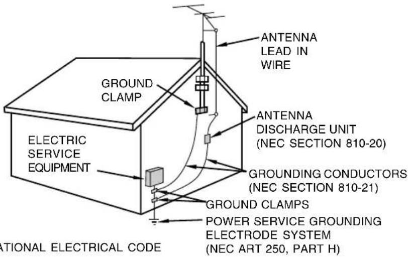
- For added protection for this equipment during a lightning storm, or when it is left unattended and unused for long periods of time, unplug it from the wall outlet and disconnect the antenna. This will prevent damage to the equipment due to lightning and power-line surges.
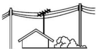
- An outside antenna system should not be located in the vicinity of overhead power lines or other electric light or power circuits, or where it can fall into such power lines or circuits. When installing an outside antenna system, extreme care should be taken to keep from touching such power lines or circuits as contact with them might be fatal.
natural_image
Simple line drawing of a utility pole with a house and power lines above (no text or symbols)- To prevent fire, never place any type of candle or flames on the top or near the TV set.
- To prevent fire or shock hazard, do not expose this product to dripping or splashing. No objects filled with liquids, such as vases, should be placed on the product.
- To prevent fire or shock hazard, do not place the AC power cord under the TV set or other heavy items.
Tips and safety instructions
- The TFT color LCD panel used in this TV is made with the application of high precision technology. However, there may be minute points on the screen where pixels never light or are permanently lit. Also, if the screen is viewed from an acute angle, there may be uneven colors or brightness. Please note that these are not malfunctions but common phenomena of LCDs and will not affect the performance of the TV.
- Do not display a still picture for a long period, as this could cause a residual image.
- If the brightness is adjusted to the minimum setting, it may be difficult to see the screen.
- The quality of the video signal may influence the quality of the display. We recommend using an equipment able to emit high quality video signals.
- Never rub or tap the TV with hard objects.
- Please understand that Sharp Corporation bears no responsibility for errors made during use by the customer or a third party, nor for any other malfunctions or damage to this product arising during use, except where indemnity liability is recognized under law.
- This TV and its accessories may be upgraded without advance notice.
Location
- Do not use the TV where ventilation is poor, where there is a lot of dust, where humidity is high, or where the TV may come into contact with oil or steam, as this could lead to fire.
- Ensure that the TV does not come into contact with water or other fluids. Ensure that no objects such as paper clips or pins enter the TV as this could lead to fire or electric shock.
- Do not place the TV on top of unstable objects or in unsafe places. Do not allow the TV to come into contact with strong shocks or vibrations. Causing the TV to fall or topple over may damage it.
- Do not use in places where the TV will be subject to direct sunlight, near heating equipment or anywhere else where there is likelihood of high temperature, as this may lead to generation of excessive heat and outbreak of fire.
Power cord
- Do not damage the power cord, place heavy objects on it, stretch it, or over bend it. Also, do not add extension cords. Damage to the cord may result in fire or electric shock.
- Use only the power cord supplied with the TV.
- Insert the power plug directly into the AC outlet. Adding an extension cord may lead to fire as a result of overheating.
- Do not remove or insert the power plug with wet hands. Doing so could result in electric shock.
Use of AC adapter
- Do not use the AC adapter for other than the specified equipment.
- Unplug the AC adapter if it is not used for a long time.
- Do not place any objects on the AC adapter.
- Do not use the AC adapter outdoors.
- Do not attempt to repair the AC adapter if it is broken or malfunctioning. Refer the servicing to the service representative.
- Do not try to open the AC adapter.
- Do not use water or wet cloth for cleaning the AC adapter.
Manual scope
- In this manual, Microsoft Windows XP will be referred to as "Windows XP", Microsoft Windows Millennium as "Windows Me", Microsoft Windows 2000 as "Windows 2000", Microsoft Windows 98 as "Windows 98", and Microsoft Windows 95 as "Windows 95". When there is no need to distinguish between programs, the term "Windows" will be used.
- Microsoft and Windows are registered trademarks of Microsoft Corporation.
- Macintosh is a registered trademark of Apple Computer, Inc.
- All other brand and product names are trademarks or registered trademarks of their respective holders.
- Actual screens and buttons may differ from those as shown in this manual.
Product and accessory checklist
Please check that the following items are included in the package.
- 23" LCD color TV (1)
- AC adapter (1) (model name: NL-A72J)
- Power cord (1)
- PC analog signal cable (1) (model name: 0LTLS20276002)
- PC audio cable (1) (model name: 0LTLS05247001)
- Antenna cable (1) (model name: 0LTLU00000004)
- Remote control (1)
- "AAA" size (UM/SUM-4) dry battery (2)
- Cable clamp (1)
- CD-ROM (Utility Disk for Windows/Macintosh) (1)
- Operation manual (1)
Notes:
- The digital signal cable (DVI-D - DVI-D) is to be purchased separately. (model name: NL-C04J)
- You are advised to retain the carton in case the TV needs to be transported.
- Sharp Corporation holds authorship rights to the Utility program. Do not reproduce it without permission.
- The shape of the supplied accessories may not be exactly the same as shown in this manual.
Main unit
Front view/right view
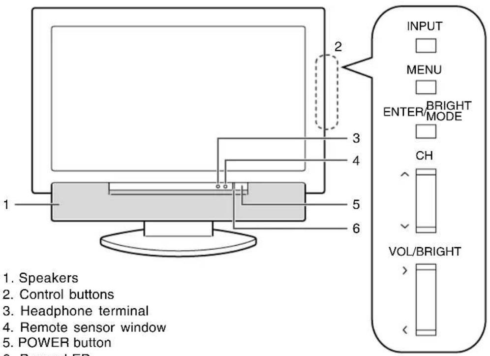
- Speakers
- Control buttons
- Headphone terminal
- Remote sensor window
- POWER button
- Power LED
Green: in use
Red: in standby mode
Orange: in power-saving mode
(only for PC mode)
Off: power off
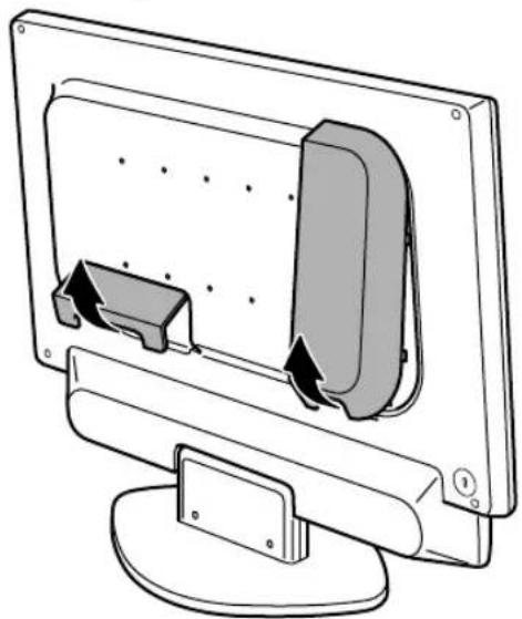
Removing/replacing the terminal cover
Removing the cover
natural_image
Diagram of a computer monitor with an open screen and a side panel, showing internal components (no text or symbols)Replacing the cover
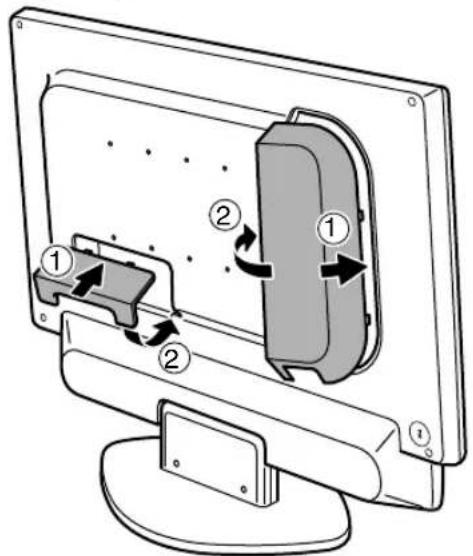
- Be careful not to pinch the cables.
Main unit
Rear view/left view
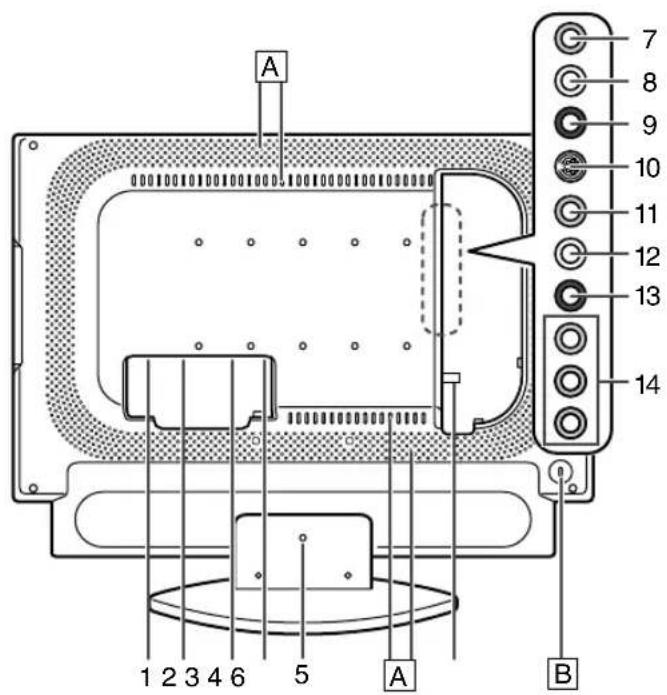
- Power input terminal
- PC digital RGB input terminal (DVI-D 24 pin)
- PC analog RGB input terminal (mini D-sub 15 pin)
- PC audio input terminal
- Lug-hole for cable clamp (See next page.)
- Antenna input terminal
- Video input terminal
- Audio input terminal - Left
- Audio input terminal - Right
- S-video input terminal
- Video input terminal
- Audio input terminal - Left
- Audio input terminal - Right
- Component input terminals
A Ventilation openings
Never block the ventilation openings as this may lead to overheating inside the TV and result in malfunction.
B Security lock anchor
By connecting a security lock (commercially available) to the security lock anchor, the TV is fixed so that it cannot be transported. The security slot works in conjunction with Kensington Micro Saver Security Systems.
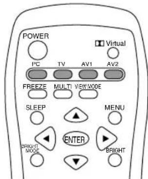
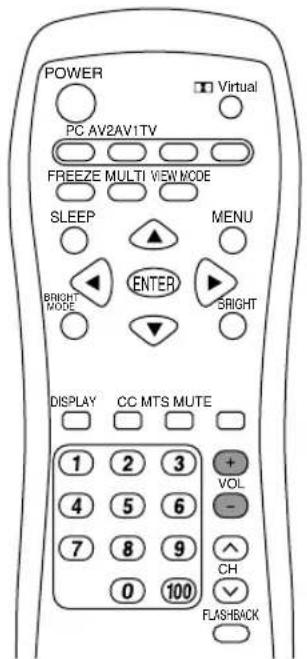
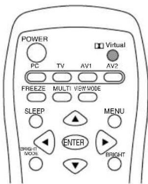
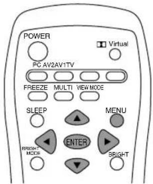
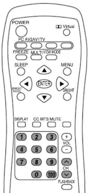
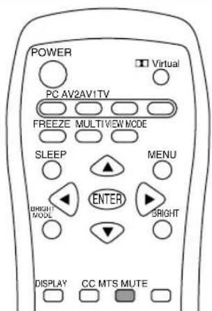
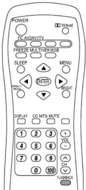
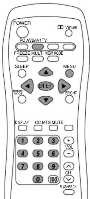
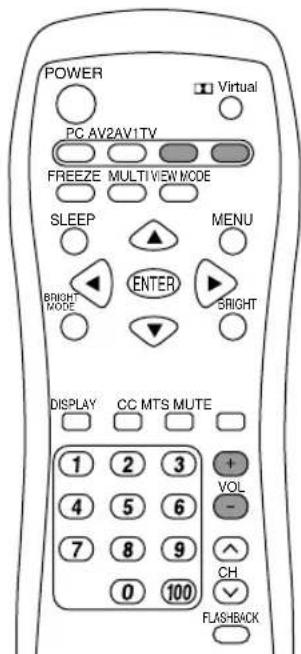
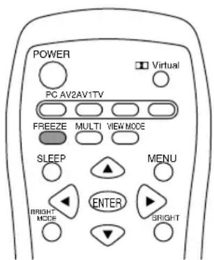
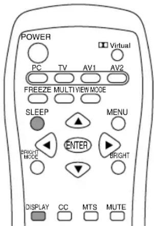
Remote control
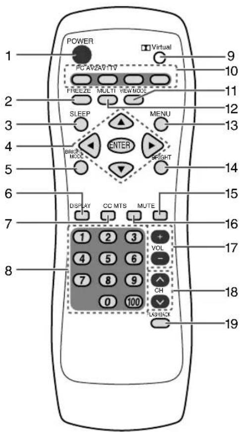
- POWER button
- FREEZE button
- SLEEP button
- ▲▼◀▶ buttons and ENTER button
- BRIGHT MODE button
- DISPLAY button
- CC (Closed Caption) button
- Channel buttons
- Dolby Virtual button
- Input buttons (PC, TV, AV1, and AV2)
- VIEW MODE button
- MULTI button
- MENU button
- BRIGHT button
- MUTE button
- MTS (Multi ch TV Sound) button
- VOL buttons
- CH (channel) buttons
- FLASHBACK button
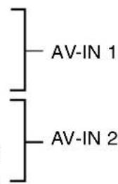
Cable clamp
Use the supplied cable clamp to secure the cables connected to the terminals.
CAUTION!
- When adjusting the viewing angle, cables may be pulled. Therefore, ensure that the cables have sufficient slack.
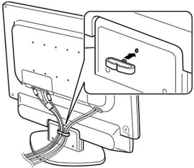
natural_image
Diagram of a computer monitor with cable routing and a close-up inset showing a device (no text or symbols present)Using headphones (commercially available)
You can connect headphones with a mini stereo jack ( 3.5 mm) to the TV.
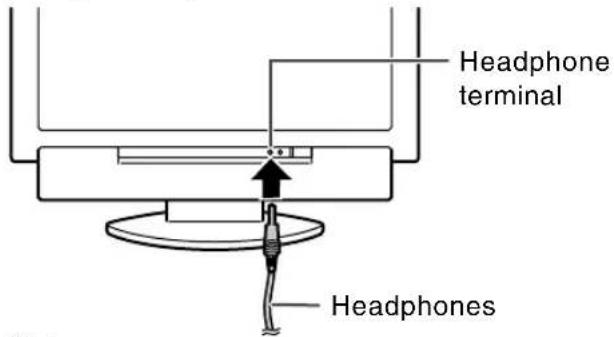
Notes:
- When headphones are connected, no sound can be heard from the TV speakers.
- When headphones are connected, the Virtual Dolby Surround function (see page E29) cannot be used.
- When headphones are connected, the AUDIO ADJUST menu (see pages E41 and E48) cannot be adjusted.
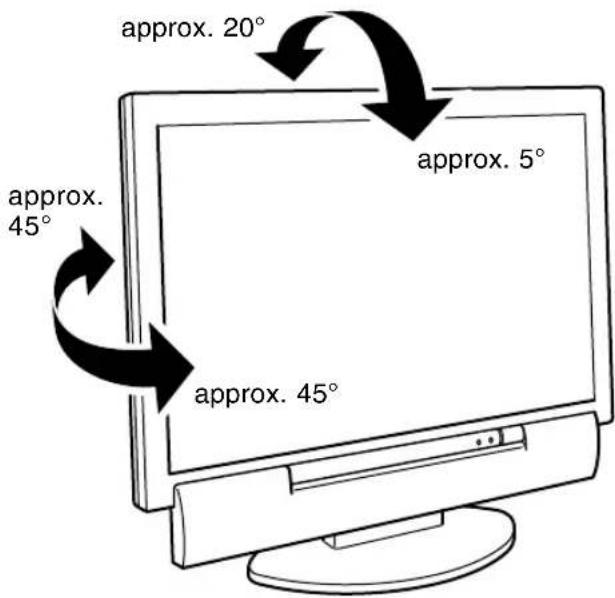
Angle adjustment
Adjust to an easy to view angle.
CAUTION!
- Be sure to hold both sides of the TV when adjusting the viewing angle. The LCD panel used in this TV is made of glass. Pressure from hands on the LCD panel could cause damage.
- Be careful not to allow your fingers to be pinched.
Remote control
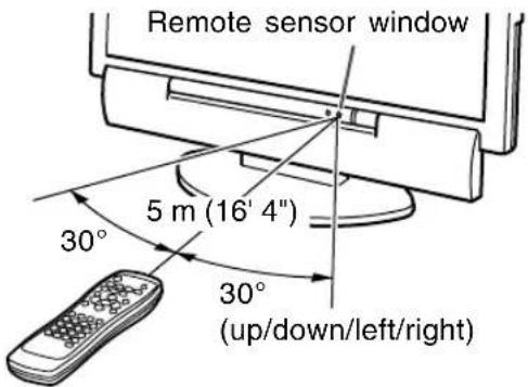
Using the remote control
Use the remote control by pointing it towards the remote sensor window on the TV. Objects between the remote control and sensor window may prevent proper operation.
Cautions regarding use of remote control
- Do not expose the remote control to shock. In addition, do not expose the remote control to liquid, and do not place in an area with high humidity.
- Do not install or place the remote control under direct sunlight. The heat may deform the unit.
- The remote control may not work properly if the remote sensor window of the TV is under direct sunlight or strong lighting, or a fluorescent light is near the TV. In such case, change the angle or place of the lighting or TV, or operate the remote control closer to the remote sensor window.
- Do not use the remote control simultaneously with remote controls of other equipment.
Batteries for the remote control
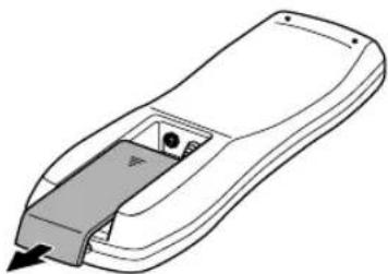
Before using the TV for the first time, install two ("AAA" size, UM/SUM-4) batteries (supplied). When the operable distance becomes shorter, replace the batteries immediately with new ("AAA" size, UM/SUM-4) batteries.
1.Open the battery cover. Slide the cover while pressing the (≠part.
natural_image
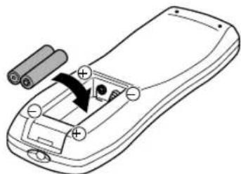
Line drawing of a remote control device with a handle and control knob (no text or symbols)- Insert two ("AAA" size, UM/SUM-4) batteries. Position the positive and negative ends of the batteries as indicated in the compartment.
natural_image
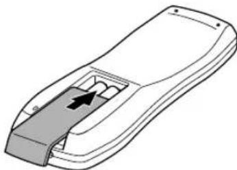
Diagram of a remote control casing with battery and indicator lights, showing internal components (no text or symbols)- Close the battery cover. Engage the claw on the cover into the battery housing and slide shut.
natural_image
Line drawing of a remote control device with a black arrow indicating a location on the side (no text or symbols)CAUTION!
Improper use of batteries can result in chemical leakage and/or explosion. Be sure to follow the instructions below.
- Place batteries with their terminals corresponding to the (+) and (−) indications.
- Different types of batteries have different characteristics. Do not mix batteries of different types.
- Do not mix old and new batteries. Mixing old and new batteries can shorten the life of new battery and/or cause the old battery to leak chemicals.
- Remove batteries when they become weak. Chemicals that leak from batteries can cause a rash. If chemical leakage is found, wipe with a cloth.
- The batteries supplied with the TV may have a shorter life expectancy due to storage conditions.
- If the remote control will not be used for an extended period of time, remove the batteries from the remote control.
TV preparation steps
Use the following steps to connect and set up your TV.

...Required when using the TV as a television

...Required when using the TV as an AV monitor

...Required when using the TV as a computer monitor

Connecting the TV to a home antenna terminal
(See pages E16 and E17.)

Connecting the TV to AV equipment (See pages E18 and E19.)
- Follow these steps to connect the TV to AV equipment and enjoy watching DVDs or playing games.

Connecting the TV to a computer (See pages E20 and E21.)
- If your computer has an analog RGB output terminal, see Analog connection on page E20.
- If your computer has a digital RGB output terminal, see Digital connection on page E21. (When using the TV with a digital connection, the separately-sold digital signal cable is required.)


Connecting the TV to a power source (See page E22.)

Setting TV channels (See pages E23 through E25.)

Adjusting the computer display automatically (See page E26.)
- Required when using the TV with an analog connection. (Not required when using the TV with a digital connection.)
Basic adjustment screen operation
The explanations in this manual use primarily the remote control.
(Operations requiring the use of control buttons on the TV are specifically identified using the words "on the TV".)
The following table shows the remote control buttons and their corresponding control buttons on the TV.
Refer to this table when using control buttons on the TV.
(For information on each control button's position on the TV, refer to page E10.)
| Remote control buttons | Function | Corresponding control buttons on the TV |
| MENU Displays the MENU | screen. MENU* | |
| Exits the MENU screen. INPUT | ||
| ▲▼ | Selects an item by moving MENU*the cursor up/down. | |
| ◀▶ | Adjusts the value. VOL/BRIGHT< > | |
| ENTER Confirms the currently ENTER/BRIGHT MODEselected item. | ||
* On the adjustment screen, moves down the cursor to select an item. If the cursor reaches the bottom item, it returns to the top item.
Connecting the TV to a home antenna terminal
CAUTION!
- When connecting, ensure that the TV is switched off.
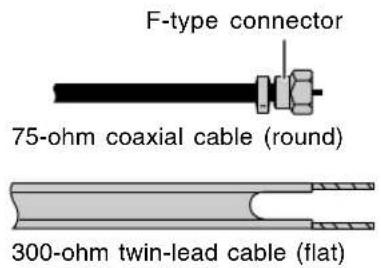
The antenna requirements for good color television reception are more important than those for black & white television reception. For this reason, a good quality outdoor antenna is strongly recommended. The following is a brief explanation of the type of connections that are provided with the various antenna systems. (See page E10 for information on removing/replacing the terminal cover.)
-
A 75-ohm system is generally a round cable with F-type connector that can easily be attached to a terminal without tools (commercially available).
-
A 300-ohm system is a flat "twin-lead" cable that can be attached to a 75-ohm terminal through a 300-75-ohm adapter (commercially available).
Notes:
- The 75-ohm coaxial cable is recommended.
- TV memory for channels is empty at shipment. To receive channels, use the CHANNEL SETTING menu. (See pages E23 through E25.)
Outdoor antenna connection
- Use one of the following two diagrams if you connect an outdoor antenna.
A: Using a VHF/UHF combination outdoor antenna.
B: Using separate VHF and/or UHF outdoor antennas.
- Connect the outdoor antenna cable lead-in to the antenna input terminal (ANT) on the left side of the TV.
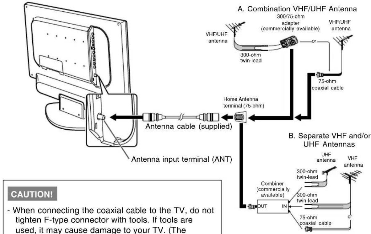
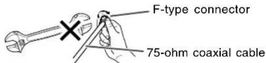
CAUTION!
- When connecting the coaxial cable to the TV, do not tighten F-type connector with tools. If tools are used, it may cause damage to your TV. (The breaking of internal circuit, etc.)
Connecting the TV to a home antenna terminal
Cable TV (CATV) connection
- A 75-ohm coaxial cable connector is built into the set for easy hookup. When connecting the 75-ohm coaxial cable to the set, screw the 75-ohm cable to the antenna input terminal (ANT).
- Some cable TV companies offer "premium pay channels". Since the signals of these premium pay channels are scrambled, a cable TV converter/descrambler is generally provided to the subscriber by the cable TV company. This converter/descrambler is necessary for normal viewing of the scrambled channels. (Set your TV to channel 3 or 4, typically one of these channels is used. If this is unknown, consult your cable TV company.) For more specific instructions on installing cable TV, consult your cable TV company. One possible method of utilizing the converter/descrambler provided by your cable TV company is explained below.
Please note: An RF switch provided with two inputs (A and B) is required (commercially available).
"A" position on the RF switch (commercially available): You can view all unscrambled channels by using the TV's channel buttons.
"B" position on the RF switch (commercially available): You can view the scrambled channels via the converter/descrambler by using the converter's channel keys.
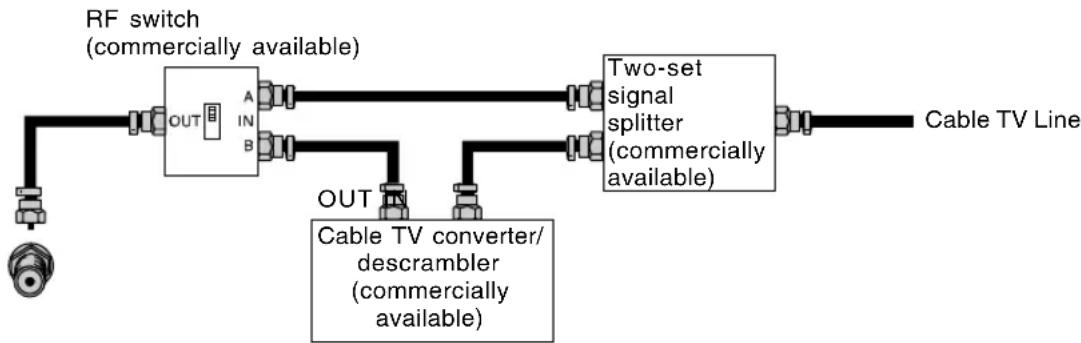
flowchart
graph LR
    A["RF switch (commercially available)"] --> B["OUT"]
    B --> C["A IN B"]
    C --> D["Two-set signal splitter (commercially available)"]
    D --> E["Cable TV Line"]
    F["Cable TV converter/descrambler (commercially available)"] --> G["OUT"]
    G --> H["OUT"]
Note:
- Consult your SHARP Dealer or Service Center for the type of splitter, RF switch, or combiner that might be required.
Connecting the TV to AV equipment
CAUTION!
- Ensure that the TV and all the equipment you are connecting to it are switched off before you begin.
See page E10 for information on removing/replacing the terminal cover.
Examples of equipment you can connect
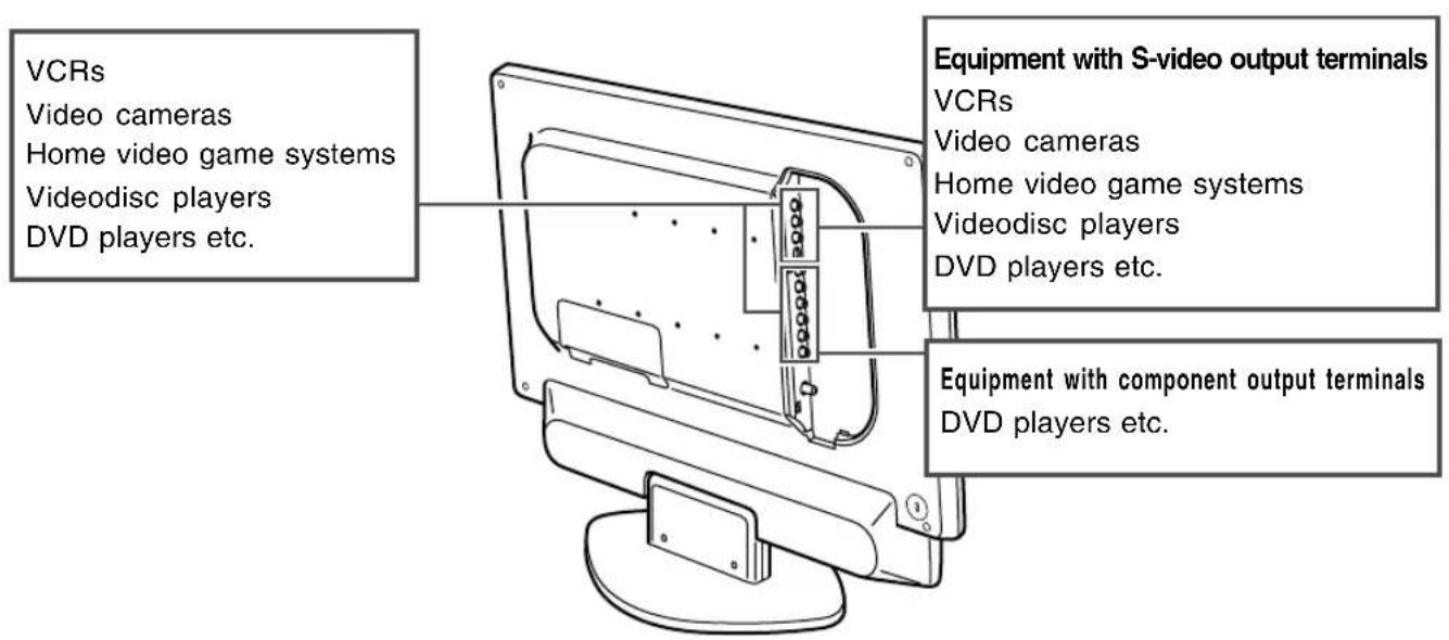
AV equipment with video output terminals
Left side of the TV
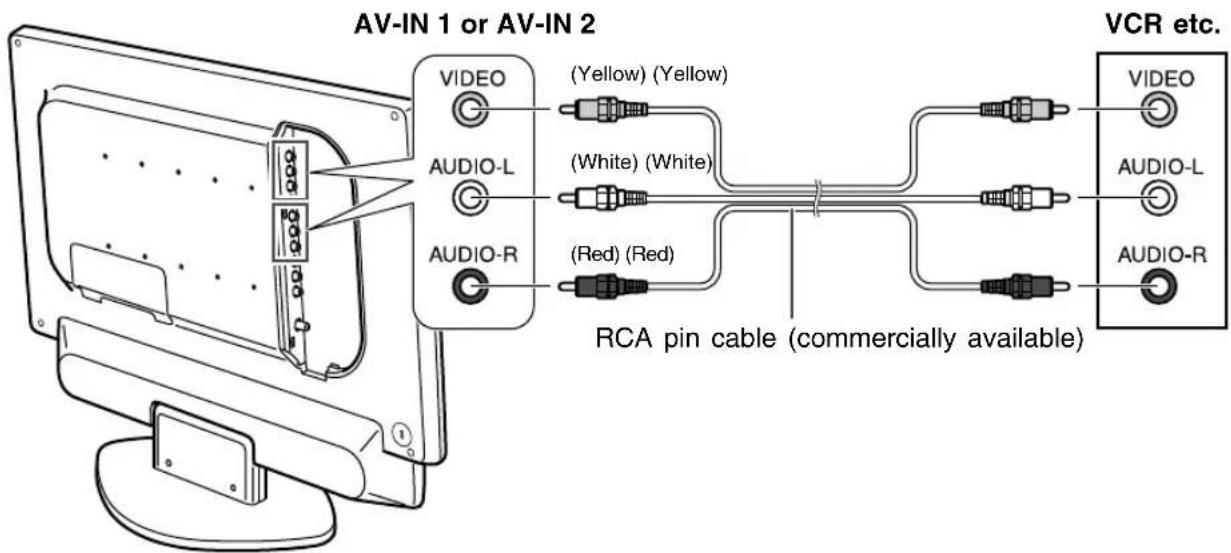
Note:
- When you are using the video input terminal, do not connect cables to the S-video input terminal and the component input terminals.
Connecting the TV to AV equipment
AV equipment with S-video output terminals
Left side of the TV
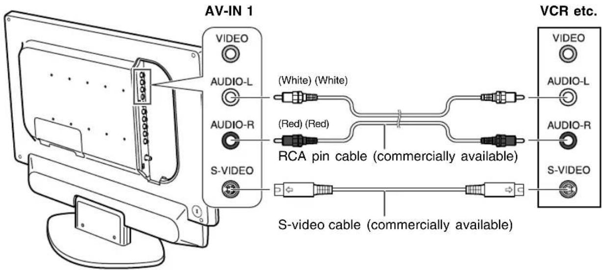
Note:
- When you are using the S-video input terminal, do not connect the cable to the video input terminal.
AV equipment with component output terminals
Left side of the TV
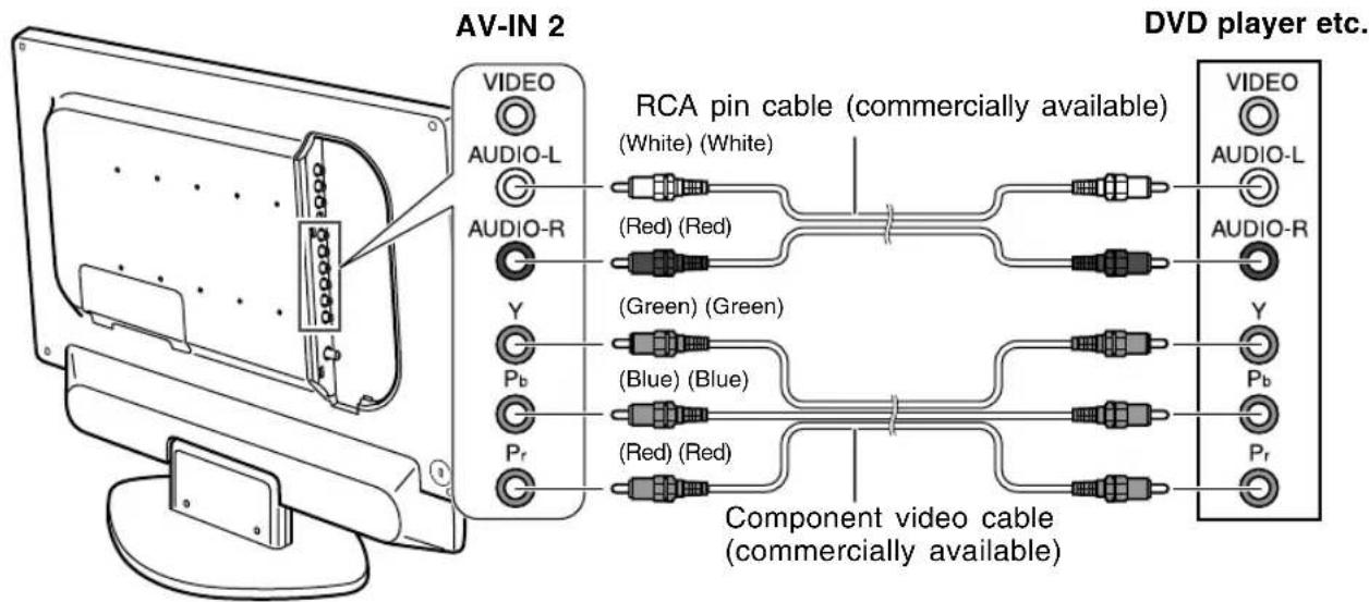
Note:
- When you are using the component input terminals, do not connect the cable to the video input terminal.
Connecting the TV to a computer
CAUTION!
- When connecting, ensure that the TV and all the equipment you are connecting to it are switched off.
- Be careful not to over bend the cable or add extension cords as this could lead to a malfunction.
Notes:
- When using the TV with an analog connection, perform an automatic screen adjustment (page E26) under the following conditions:
- Using the TV for the first time.
-
After having changed the system settings during use.
-
When using the TV with a digital connection, automatic screen adjustment is unnecessary.
- Depending on the computer or OS, you may have to install the set-up information for the TV. (See page E51.)
- When connecting to a notebook computer and the notebook computer's screen is set so that it is displaying at the same time, the MS-DOS screen may not be able to display properly. In this case, change the settings so that only the TV is displaying.
Analog connection
Connect the supplied PC analog signal cable to the analog RGB output terminal of the computer. See page E10 for information on removing/ replacing the terminal cover.
PC analog RGB input terminal (Mini D-sub 15 pin, 3 rows)
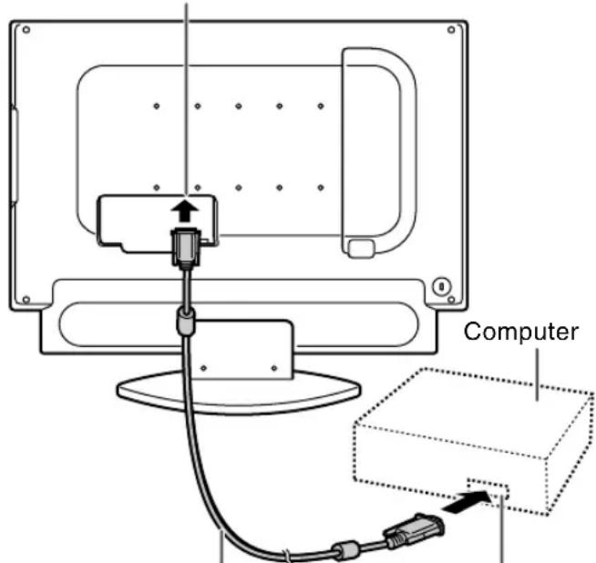
PC analog signal cable (supplied)
Analog RGB output terminal (Mini D-sub 15 pin, 3 rows)
- Paying attention to the connector direction, firmly insert the signal cable straight into the connector, and then tighten the screws at both ends.
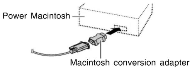
If connecting to a D-sub 15 pin 2 row Apple Power Macintosh, attach a Macintosh conversion adapter (commercially available) to the analog signal cable.
Connecting the TV to a computer
Digital connection
Connect the separately-sold digital signal cable (model name: NL-C04J) to the digital RGB output terminal of the computer.
See page E10 for information on removing/ replacing the terminal cover.
- The TV has an input terminal for connecting to a computer with a DVI-compatible output terminal (DVI-D 24 pin or DVI-I 29 pin). (Depending on the type of computer to be connected, the display may not work correctly.)
PC digital RGB input terminal (DVI-D 24 pin)
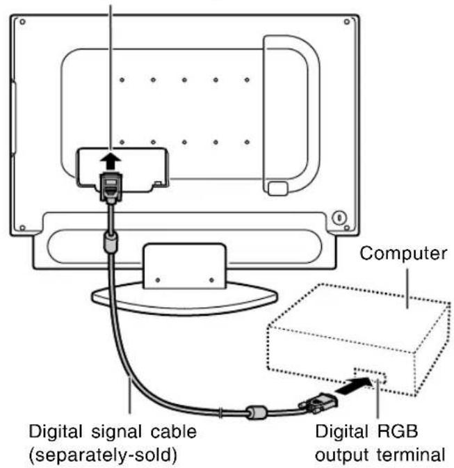
- Paying attention to the connector direction, firmly insert the signal cable straight into the connector, and then tighten the screws at both ends.
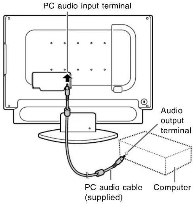
Connecting the audio cable
Connect the supplied PC audio cable to the audio output terminal of the computer.
See page E10 for information on removing/ replacing the terminal cover.
Connecting the TV to a power source
CAUTION!
- When connecting, ensure that the TV is switched off.
- Always use the AC adapter that came with the TV.
- Be careful not to over bend the cable or add extension cords as this could lead to a malfunction.
See page E10 for information on removing/replacing the terminal cover.
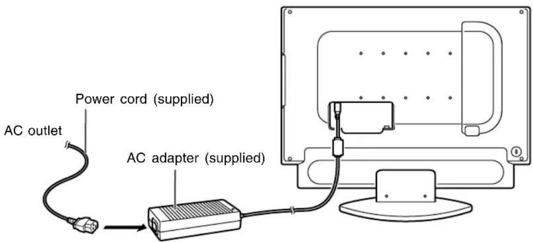
- Connect the AC adapter to the power input terminal.
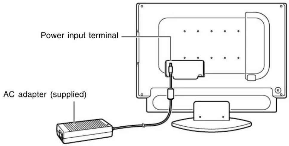
- Plug the power cord into the AC adapter and then place the power plug into an AC outlet.
Note:
- If the TV does not operate, disconnect the power cord from the AC outlet and reconnect it again. The setup must be completed in the proper order for the TV to function.
Setting TV channels
The following table shows the channels this TV can receive.
VHF Channels 2 through 13
UHF Channels 14 through 69
Cable
Channel 1 (HRC and IRC mode only)
Channels 2 through 125 (STD, HRC, and IRC)
(You must subscribe to a cable TV service to receive cable channels.)
TV memory for channels is empty at shipment. To receive channels, use the CHANNEL SETTING menu.
Note:
- Release the adjustment lock (see page E56) if it has been set. You cannot use the CHANNEL SETTING menu while the adjustment lock is set.
Channel setting methods
There are two ways to set channels.
Automatically setting channels you can receive (CHANNEL SEARCH)
The TV will automatically set the channels it can receive in your area.
Setting channels one at a time (CHANNEL MEMORY)
This method is for manually setting the channels you want one by one. Use this method if you want to add other channels after using "CHANNEL SEARCH".
Displaying the CHANNEL SETTING menu
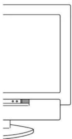
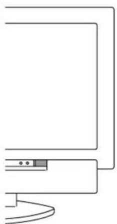
natural_image
Simple line drawing of a computer monitor with a curved base and two small buttons, no text or symbols present.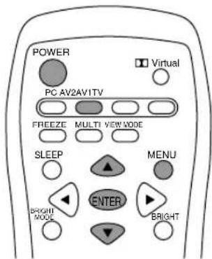
- Press the POWER button on the TV to turn on the TV.
When the power LED lights red, press the POWER button on the remote control.
- Press the TV button to select TV mode. A channel number will appear in the upper-right corner of the screen.
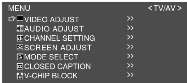
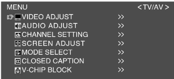
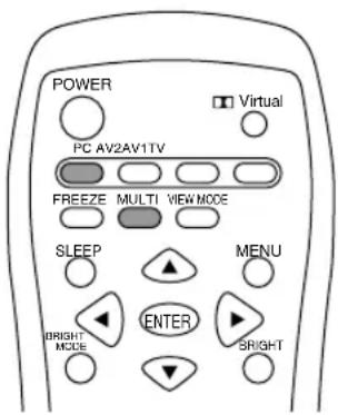
- Press the MENU button to display the MENU screen.
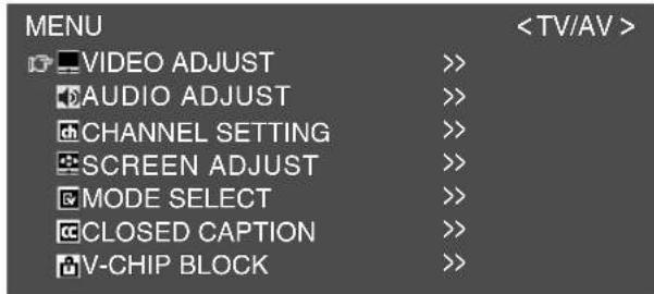
- Press the ▲▼ buttons to select "CHANNEL SETTING", and press the ENTER button.
The CHANNEL SETTING menu will be displayed.
![CHANNEL SETTING +RETURN AIR/CABLE [ AIR ] CABLE MODE [ STD ] CHANNEL SEARCH >> CHANNEL MEMORY >>](/content/2026/05/1070128/images/a0b04529e747664ada4fc6e8aa3cb5aebaecfaa335fc5e64f7306b99d1c0b452.jpg)
Selecting broadcast (AIR) or cable TV (CABLE) for channel setting
It is necessary to set the receiving mode to "AIR" or "CABLE" channels to receive locally broadcast TV programs.
- Display the CHANNEL SETTING menu. (See page E23.)
- Press the ▲▼ buttons to select "AIR/CABLE", and press the ENTER button.
- Press the ◀▶ buttons to select the desired mode ("AIR" or "CABLE"), and press the ENTER button.
If you select "CABLE":
(1) Press the ▲▼ buttons to select "CABLE MODE", and press the ENTER button.
(2) Press the ◀▶ buttons to select the desired mode ("STD", "HRC", or "IRC"). - Press the MENU button to exit the screen.
Saving broadcast TV channels in the memory (CHANNEL SEARCH)
"CHANNEL SEARCH" allows you to search through available channels ("AIR" or "CABLE") in your area.
The tuner saves them to TV memory automatically.
-
Display the CHANNEL SETTING menu. (See page E23.)
-
Press the ▲▼ buttons to select "CHANNEL SEARCH", and press the ENTER button.

- Press the ENTER button.
The tuner will search through all available channels in your area and save them to the TV memory.
Note:
- To interrupt Channel Search, press the MENU button. Channel Search will stop at the current channel and will not save any higher channels.
- When Channel Search completes, the CHANNEL SEARCH screen becomes off and TV screen becomes minimum channel of TV memory.
If TV memory is empty, TV channel will be CH 2 (AIR and CABLE: STD) or CH 1 (CABLE: HRC and IRC).
Notes:
- Searching channels are:
AIR channels:
VHF: 2 through 13
UHF: 14 through 69
CABLE channels:
1 (HRC and IRC mode only)
2 through 125 (STD, HRC, and IRC)
- During Channel Search, the TV will change channels automatically.
- When Channel Search completes, all channels, which were set previously, will be erased.
- If you search for channels but cannot receive any, TV memory becomes empty.
Adding weak or additional channels or erasing unwanted channels from TV memory (CHANNEL MEMORY)
Using "CHANNEL MEMORY", you can add channels that could not be saved by "CHANNEL SEARCH" because the signal was too weak.
- Display the CHANNEL SETTING menu. (See page E23.)
- Press the ▲▼ buttons to select "CHANNEL MEMORY", and press the ENTER button.
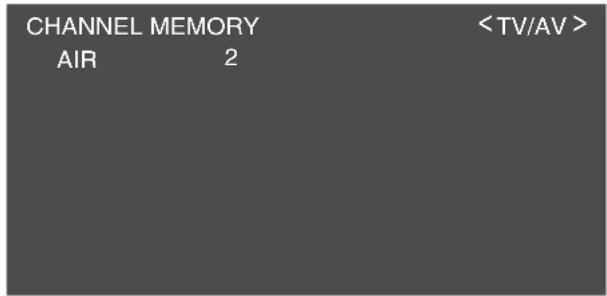
- Press the CH buttons or the ▲▼ buttons to select each desired channel to add or erase. You can also use the channel buttons.
- Press the ▶ button to add the channel to the TV memory. To erase the channel from the TV memory, press the ◀ button.
- Press the MENU button to exit the screen.
Adjusting the computer display automatically (for analog signals)
When using the TV as a computer display for the first time or after having changed the system settings during use, perform an automatic screen adjustment. "CLOCK", "PHASE", "H-POS", and "V-POS" will be set to their optimum states.
Note:
- When using the TV with a digital connection, automatic screen adjustment is unnecessary.

natural_image
Simple line drawing of a computer monitor with a cable and indicator lights (no text or symbols)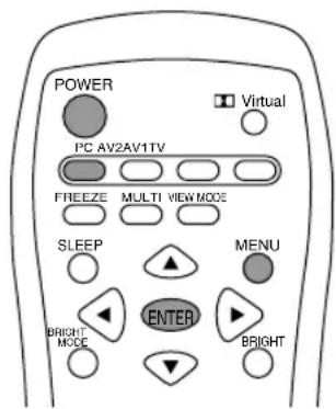
- Press the POWER button on the TV to turn on the TV.
When the power LED lights red, press the POWER button on the remote control.
- Press the PC button to select the PC (analog) mode.
"PC" and "ANALOG" will appear in the upper-right corner of the screen.
If "PC" and "DIGITAL" appear, press the PC button again.
- Turn on the computer, and then display an image that makes the entire screen display light colors (such as a light desktop background).
If you are using Windows, use the adjustment pattern on the supplied CD-ROM (see page E46).
- Press the MENU button to display the MENU screen.
The cursor is positioned at "ADJUSTMENT".
| MENU | <PC> | |
| ADJUSTMENT | >> | |
| GAIN CONTROL | >> | |
| AUDIO ADJUST | >> | |
| COLOR CONTROL | >> | |
| MODE SELECT | >> | |
| MULTI SCREEN | >> | |
- Press the ENTER button.
The ADJUSTMENT menu will be displayed.
![ADJUSTMENT < PC> RETURN AUTO CLOCK [ 127 ] >> PHASE [ 0 ] >> H-POS [ 200 ] >> V-POS [ 50 ] >> RESET](/content/2026/05/1070128/images/52001009571e14e8ba0e2791065738577c4d22b9349dbbbb353e76fc4815db64.jpg)
- Press the ENTER button to auto-adjust the settings.
The screen will go dark and "ADJUSTING" will be displayed. After a few seconds, the ADJUSTMENT menu will return.
- Press the MENU button to exit the screen.
Notes:
- If you want to select a screen resolution of 1360 x 768, 1280 x 768, or 1024 x 768 when using the TV with an analog connection, specify the horizontal resolution for a 768-line screen in the MODE SELECT menu (PC mode). (See page E49.)
- If you want to select a screen resolution of 640 x 480 or 848 x 480 when using the TV with an analog connection, specify the horizontal resolution for a 480-line screen in the MODE SELECT menu (PC mode). (See page E49.)
- It may not be possible to achieve correct adjustment with the first automatic adjustment. In such a case, try repeating the automatic adjustment 2 or 3 times.
- If necessary due to any of the following, manual adjustments can be performed after the automatic adjustment. (See page E45.)
- When further fine adjustment is needed.
- When the computer's video input signals are Composite Sync or Sync on Green. (Automatic adjustments may not be possible.)
- When "OUT OF ADJUST" is displayed. (When the screen displays an entirely dark image, the automatic screen adjustment may be disabled. When making an automatic adjustment, be sure to either use the adjustment pattern or try displaying an image that makes the entire screen very bright.)
- Automatic adjustment may not be achieved correctly depending on what is displayed on the screen - moving pictures or the MS-DOS prompt etc.
Turning power on/off
natural_image
Pure line drawing of a computer monitor with a curved base and two small buttons, no text or symbols present.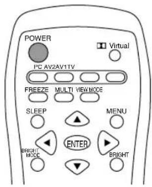
Turning power on
When the power LED is off:
- Press the POWER button on the TV.
- Turn on power for the connected equipment. After a while the power LED will light green, and then the display mode will be displayed for several seconds.
When the power LED is lit red (standby):
-
Press the POWER button on the remote control.
-
Turn on power for the connected equipment. The power LED will light green, and then the display mode will be displayed for several seconds.
Turning off power
- Turn off power for the connected equipment.
- Press the POWER button on the remote control. The power LED will light red (standby).
- Press the POWER button on the TV. The power LED will go out.
Notes:
- Always wait at least 5 seconds between switching power off/on. Rapid switching may damage the TV or cause it to malfunction.
- After switching power on, it may take a little while before the screen displays an image.
- Do not turn off the power immediately after changing various settings on the screen. The changed values may not have been saved in the memory yet.
Switching display modes (INPUT)
- Press the PC, TV, AV1, or AV2 button.
The TV will switch to the display mode for the button you pressed.
Each time you press the PC button, the input toggles between analog and digital.
10
STEREO
Display modes
| Number | TV mode Displays the TV's image. The number is the channel being received. |
| AV1 | AV1 mode Displays the image from the equipment connected to the AV1 input. |
| AV2 | AV2 mode Displays the image from the equipment connected to the AV2 input. |
| PC PC mode (analog/digital) image. | |
Notes:
- When you turn on the TV, the initial display mode will be the mode being used when the TV was last turned off. (The factory setting is TV.)
- The CH buttons or channel buttons (0-9 and 100) also automatically switch to TV mode, except for the following cases when in PC mode.
- When watching TV in the PIP/SPLIT window. (See page E43.)
- When listening to the TV. (See page E44.) In these cases, press the TV button to switch the display mode to TV.
- Pressing the INPUT button on the TV also changes the display mode. Each time you press the button, the input changes in the following order:
Number (TV) → AV1 → AV2 → PC (analog) → PC (digital) → Number (TV)...
- In PC mode, when there is no input signal, "NO SIGNAL" is displayed.
Adjusting the backlight
The brightness of the backlight can be set individually for PC mode and TV/AV mode. Start by switching to the display mode for which you want to adjust the backlight.
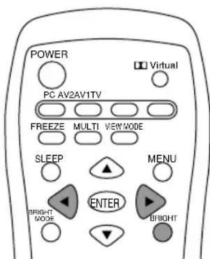
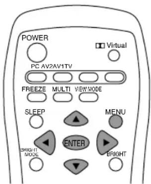
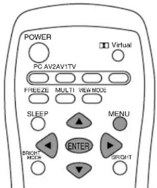
- Press the BRIGHT button.

- Press the ◀▶ buttons to adjust the brightness.
Increase ▶ button
Decrease button
The screen for adjusting the brightness will automatically disappear after several seconds.
Note:
- You can also adjust the brightness using the control buttons on the TV.
- Press the VOL/BRIGHT buttons.
- Press the MENU button to select "BRIGHT".
- Press the VOL/BRIGHT buttons to adjust the brightness.
Increase VOL/BRIGHT > button
Decrease VOL/BRIGHT < button
The screen for adjusting the brightness will automatically disappear after about 15 seconds.
Adjusting the volume
The volume can be set individually for PC mode and TV/AV mode. Start by switching to the display mode for which you want to set the volume.
- Press the VOL +/- buttons to adjust.

Increase VOL + button
Decrease VOL - button
The screen for adjusting the volume will automatically disappear after several seconds.
Notes:
- When headphones are connected, these buttons automatically become the headphone volume control. (♀ will appear on the screen.)
- You can also adjust the volume using the control buttons on the TV.
- Press the VOL/BRIGHT buttons.
- Press the MENU button to select "VOLUME".
- Press the VOL/BRIGHT buttons to adjust the volume.
Increase VOL/BRIGHT > button
Decrease VOL/BRIGHT < button
The screen for adjusting the volume will automatically disappear after about 15 seconds.
Enjoying surround sound (Virtual Dolby Surround)
The Virtual Dolby Surround function allows you to enjoy powerful, realistic sound, just like in a movie theater.

Manufactured under license from Dolby Laboratories.
"Dolby", "Pro Logic" and the double-D symbol are trademarks of Dolby Laboratories.
- Press the Dolby Virtual button. Each time you press the button, the function turns "ON" or "OFF".
Note:
- When headphones are connected, the Virtual Dolby Surround function cannot be used.
Selecting the language on the screen
You can select the language (English/Spanish/French) using the MODE SELECT menu while in any mode. (The selected language will be displayed in all modes.)
- Press the MENU button to display the MENU screen.
- Press the ▲▼ buttons to select "MODE SELECT", and press the ENTER button.
- Press the ▲▼ buttons to select "LANGUAGE", and press the ENTER button.
- Press the ◀▶ buttons to select the language you want to display.
- Press the MENU button to exit the screen.
Watching TV
TV memory for channels is empty at shipment. The first time you use the TV or when you move to a new area, set the channels using the CHANNEL SETTING menu. (See page E23.)
- Select a channel using the CH buttons or channel buttons.
Pressing one of these buttons automatically switches to TV mode if the TV is in PC or AV mode.
To select a 1- or 2-digit channel number (e.g., Channel 5):
Complete the following procedure within 4 seconds.
- Press the 0 button.
- Press the 5 button.
Note:
- When selecting a 1-digit channel number, do not fail to press the 0 button first.
To select a 3-digit channel number (e.g., Channel 115):
Complete the following procedure within 4 seconds.
- Press the 100 button.
- Press the 1 button.
-
Press the 5 button.
-
Adjust the volume.
See page E29 for more information.
Notes:
- To switch the display mode to TV in the following cases when in PC mode, press the TV button.
- When watching TV in the PIP/SPLIT window. (See page E43.)
- When listening to the TV. (See page E44.)
- The 3-digit channel number can be selected only when the receiving mode is set to "CABLE" in the CHANNEL SETTING menu. (See pages E23 and E24.)
- You can also change the channel up/down one at a time using the CH buttons on the remote control and the TV.
Selecting MTS (Multi ch TV Sound)
You can select MTS (Multi ch TV Sound) using the MTS button.
STEREO stereo audio
SAP second audio program
MONO monophonic audio
- Press the MTS button.
The audio changes in the following order depending on the broadcast you are receiving.
Receiving a stereo broadcast:
STEREO → STEREO → MONO → STEREO...
Receiving a monaural + SAP (Second Audio Program) broadcast:
MAIN → SAP → MONO → MAIN...
Receiving a stereo + SAP (Second Audio Program) broadcast:
ST (SAP) → SAP (ST) → MONO → ST (SAP)...
Note:
- Switch to "MONO" if there is too much noise during a stereo broadcast.
Returning to previous channel (FLASHBACK)
You can return to the previous channel you were watching.
- Press the FLASHBACK button.
The TV will return to the channel you were previously watching.
Setting the Closed Caption (CLOSED CAPTION)
This TV is equipped with an internal Closed Caption decoder. "Closed Caption" is a system which allows conversations, narration, and sound effects in TV programs and home videos to be viewed as captions on the TV screen.
- Not all programs and videos will offer Closed Captioning.
- The Closed Caption broadcasts can be viewed in 2 modes: Caption (CAPTION) and Text (TEXT).
For each mode, two channels are available: CH1 and CH2.
The CAPTION mode shows subscripts of dialogs and commentaries of TV dramas and news programs while allowing a clear view of the picture.
The TEXT mode displays various information over the picture (such as TV program schedules and weather forecasts, etc.) that is independent of the TV programs.
Perform this procedure using the CC button or the CLOSED CAPTION menu.
Here we will describe the procedure using the CC button.
(See page E42 for information on using the menus.)
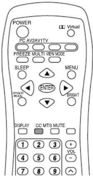
- Press the CC button to display the CC/TEXT screen.
CC/TEXT: OFF
- Press the CC button to change the setting.
The setting changes in the following order:
OFF → CC1 → CC2 → TEXT1 → TEXT2 → OFF...
| CC1 | Caption mode for CH1 data |
| CC2 | Caption mode for CH2 data |
| TEXT1 | Text mode for CH1 data |
| TEXT2 | Text mode for CH2 data |
Notes:
- If a broadcast has Closed Caption and the MUTE button is pressed, the TV enters the Caption mode automatically. Pressing the MUTE button again will return the TV to its previous condition.
- Closed Caption may malfunction (white blocks, strange characters, etc.) if signal conditions are poor or if there are problems at the broadcast source.
- If no text broadcast is being received while viewing in the Text mode, the screen may become dark and blank for some programs. Should this occur, switch the Closed Caption mode to "OFF".
Adjusting the V-chip settings (V-CHIP)
Important:
- Please refer to the end of this manual for "Clearing the secret number".
This function allows TV programs to be restricted and TV usage to be controlled based on FCC data. It prevents children from watching violent or sexual scenes that may be harmful.
- Restriction of TV programs includes two ratings that contain information about the program: the MPAA rating and the TV Parental Guidelines. The MPAA rating is restricted by age. TV Parental Guidelines are restricted by age and content.
- Since a TV program may use either the MPAA rating or the TV Guidelines, both should be adjusted for complete control.
Voluntary movie rating system (MPAA rating)
| Rating | ||
| Age base | G | GENERAL AUDIENCES. All ages admitted. |
| PG | PARENTAL GUIDANCE SUGGESTED. Some material may not be suitable for children. | |
| PG-13 | PARENTS STRONGLY CAUTIONED. Some material may be inappropriate for children under 13. | |
| R | RESTRICTED. Under 17 requires accompanying parent or adult guardian. | |
| NC-17 | NO ONE 17 AND UNDER ADMITTED. | |
| X | X is an older rating that is unified with NC-17 but may be encoded in the data of older movies. | |
For example:
PG-13 in the age-based rating is blocked, this will also automatically block the higher ratings (R, NC-17, and X).
- User setting
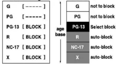
Note:
- The MPAA rating is only age-based.
Watching TV
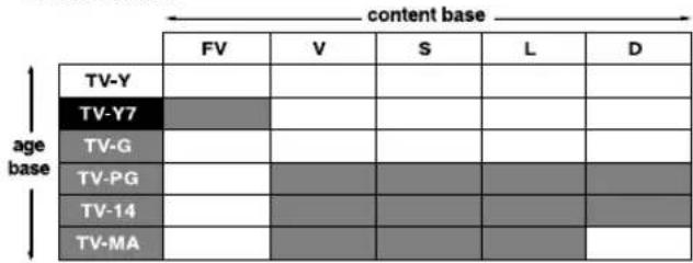
TV Parental Guidelines
| Rating | Content base | |||||
| FV(Fantasy violence) | V(Violence) | S(Sexual situation) | L(Adult language) | D(Sexually suggestive dialog) | ||
| Age base | TV-Y (All children) | |||||
| TV-Y7 (Direct to older children) | × | |||||
| TV-G (General audience) | ||||||
| TV-PG(Parental guidance suggested) | × | × | × | × | ||
| TV-14(Parents strongly cautioned) | × | × | × | × | ||
| TV-MA (Mature audience only) | × | × | × | |||
*The content rating can be set.
Example 1:
When TV-Y7 in the age-based rating is set to BLOCK, this will automatically block the higher ratings: TV-G, TV-PG, TV-14, and TV-MA. In addition, D, L, S, V, and FV in CONTENT are automatically blocked unless you manually set BLOCK CONTENT.
-
User setting
-
Block table

Select block

auto-block
Example 2:
When the content-based rating: "D for TV-PG" is blocked, this will automatically block the higher rating: "D for TV-14".
-
User setting

-
Block table

Select block

auto-block
Notes:
- Age-based ratings can be modified by the content-based ratings, but only in the combinations indicated by an "X" in the table above.
- Choosing a lower age-based rating blocks the higher age-based ratings regardless of content rating settings.
Setting V-chip for MPAA rating
- Press the TV button to select TV mode.
- Press the MENU button to display the MENU screen.
- Press the ▲▼ buttons to select "V-CHIP BLOCK", and press the ENTER button.
"INPUT SECRET NO." screen will be displayed.
- Input the 4-digit secret number using the channel buttons (0-9).
Note:
- When you input the secret number for the first time, press the ENTER button to register it. Otherwise, continue to the next step.
The V-CHIP BLOCK menu will be displayed.
![V-CHIP BLOCK + RETURN MPAA > TV GUIDELINES > STATUS [ OFF ] RESET](/content/2026/05/1070128/images/c7be035a530c4725de93a761b3f6ec018c4eec97516f204341d3ddb0dccc44da.jpg)
- Press the ▲▼ buttons to select "MPAA", and press the ENTER button.
- Press the ▲▼ buttons to select, for example, "PG", and press the ENTER button.
- Press the ◀▶ buttons to select "BLOCK". If you set "PG" to "BLOCK", then "PG-13", "R", "NC-17", and "X" are automatically blocked.
- Press the MENU button to exit the screen.
Notes:
- Set ratings are blocked only when you activate V-chip Block (see page E37).
- If you set "G" to "BLOCK", all ratings are automatically blocked.
- If you set "X" to "BLOCK", then "G", "PG", "PG-13", "R", and "NC-17" are not blocked.
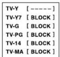
Setting V-chip for TV Parental Guidelines (TV GUIDELINES)
- Repeat steps 1 to 4 of "Setting V-chip for MPAA rating" on the left column.
(The V-CHIP BLOCK menu will be displayed.) - Press the ▲▼ buttons to select "TV GUIDELINES", and press the ENTER button.
- Press the ▲▼ buttons to select, for example, "TV-Y7", and press the ENTER button.
- Press the ◀▶ buttons to select "BLOCK".
![TV GUIDELINES RETURN TV-Y [ ---- ] TV-Y7 [ BLOCK ] TV-G [ BLOCK ] TV-PG [ BLOCK ] TV-14 [ BLOCK ] TV-MA [ BLOCK ] BLOCK CONTENT >>](/content/2026/05/1070128/images/a76d290d5708960a9375a2172b4d07b10948961e742b9f84fa51593ec9a9be31.jpg)
If you set "TV-Y7" to "BLOCK", then "TV-G", "TV-PG", "TV-14", and "TV-MA" are automatically blocked. In addition, "D", "L", "S", "V", and "FV" in CONTENT are automatically blocked.
- Press the MENU button to exit the screen.
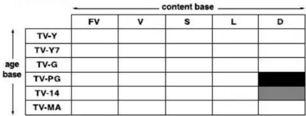
Setting V-chip for Block Content (BLOCK CONTENT)
- Repeat steps 1 to 4 of "Setting V-chip for MPAA rating" on page E36. (The V-CHIP BLOCK menu will be displayed.)
- Press the ▲▼ buttons to select "TV GUIDELINES", and press the ENTER button.
- Press the ▲▼ buttons to select "BLOCK CONTENT", and press the ENTER button.
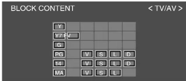
- Select the desired cell (with character) on the screen using the ▲▼◀▶ buttons.
- Press the ENTER button. Each time you press the button, the color of the selected cell switches between black (blocked) and gray (unblocked).
- Press the MENU button to exit the screen.
Note:
- If you set "TV-14" to "BLOCK", "TV-MA" is automatically blocked. Contents "D", "L", "S", and "V" are automatically blocked in the table on page E35.
Activating or deactivating V-chip Block (Setting STATUS)
You can activate V-chip Block after "Setting V-chip for MPAA rating" and/or "Setting V-chip for TV Parental Guidelines (TV GUIDELINES)".
- Repeat steps 1 to 4 of "Setting V-chip for MPAA rating" on page E36. (The V-CHIP BLOCK menu will be displayed.)
- Press the ▲▼ buttons to select "STATUS", and press the ENTER button.
- Press the ◀▶ buttons to set "STATUS" to "ON" (activated) or "OFF" (deactivated).
Note:
- If "STATUS" is set to "OFF", V-chip Block will not be activated.
- Press the MENU button to exit the screen.
Note:
- When "STATUS" in the V-CHIP BLOCK menu is "ON", TV/AV-IN SOUND is not available in PC mode (see page E44).
Canceling V-chip Block temporarily
1."V-CHIP HAS BEEN ACTIVATED" appears if you watch a program with the same Program Rating data you configured.
Note:
- "V-CHIP HAS BEEN ACTIVATED" will not be displayed if "STATUS" is not configured to "ON".
- Press the ENTER button to display "INPUT SECRET NO.".
- Input the 4-digit secret number using the channel buttons (0-9).
V-chip Block is temporarily canceled. If you input an incorrect secret number, "SECRET NO. IS INCORRECT" is displayed. In this case, input the correct secret number.
Notes:
- If you display the V-CHIP BLOCK menu again (see page E36), V-chip Block will be activated again.
- If you turn the power on from off, V-chip Block will be activated again.
Resetting the V-chip Block settings
The settings will be reset to the default status. However, the secret number will not be cleared.
- Repeat steps 1 to 4 of "Setting V-chip for MPAA rating" on page E36. (The V-CHIP BLOCK menu will be displayed.)
- Press the ▲▼ buttons to select "RESET", and press the ENTER button.
- Press the MENU button to exit the screen.
Enjoying DVDs, games, and other equipment
You can enjoy two additional pieces of AV equipment connected to your TV such as VCRs, DVD players, and game systems. (See page E18.)
Equipment connected to AV-IN 1 Display mode "AV1" Equipment connected to AV-IN 2 Display mode "AV2"
Note:
- Since the use of AV1 and AV2 is the same, this manual refers to AV1 mode and AV2 mode as "AV mode".
- Press the AV1 or AV2 button to select the AV1 or AV2 mode.
AV1
VIDEO
-
Turn on the connected AV equipment, and then play a tape, DVD, or game.
-
Adjust the volume.
See page E29 for more information.
Notes:
- Sometimes no image will be displayed during fast searching of video.
- The display may flicker during slow playback of video depending on the VCR or videotape you are using.
- You cannot play shooting games that use gun controllers with this TV.
Pausing the screen (FREEZE)
This feature pauses the image from the TV or other connected AV equipment. This is handy when you want to write down a recipe or the address for a prize contest.
- Press the FREEZE button. The images will pause.
Canceling pausing
- Press the FREEZE button again.
Notes:
- You cannot pause the image displayed in the PIP/SPLIT window.
- Changing channels or switching the display mode (input) automatically cancels pausing.
- The screen size cannot be changed using the VIEW MODE button while an image is paused. The SCREEN ADJUST menu also cannot be adjusted while an image is paused.
Switching power off after a specified length of time (SLEEP)
The TV can automatically switch off (standby) after a specified length of time. This is handy if you want to use the TV at bedtime.
- Press the SLEEP button.
- Specify in how many minutes you want the TV to switch off by pressing the SLEEP button.
The time changes in the following order each time you press the button:
$$ \begin{array}{l}3 0 \min \rightarrow 6 0 \min \rightarrow 9 0 \min \rightarrow 1 2 0 \min \rightarrow\1 5 0 \min \rightarrow - - \min \rightarrow 3 0 \min\end{array} $$
When the specified time elapses, the TV automatically switches off and clears the SLEEP timer.
Checking the time remaining on the SLEEP timer
- Press the DISPLAY button.
The time remaining on the SLEEP timer will be displayed for about 5 seconds. You can also check the time remaining by pressing the SLEEP button once.
Changing the specified time
- Press the SLEEP button.
The remaining time will be displayed. - Change the specified time by pressing the SLEEP button several times as needed.
Notes:
- When there are only 5 minutes remaining on the SLEEP timer, the remaining time will be displayed every minute.
- Pressing the POWER button while the SLEEP timer is operating will clear the timer.
- Switching to PC mode automatically clears the SLEEP timer.
- You can also set the SLEEP timer from the MODE SELECT menu. (See page E42.)
Using the menus in TV/AV mode
You can adjust TV and video images and perform various settings using the menus in TV/AV mode.
- All the menus except for the CHANNEL SETTING menu are common for TV and AV modes. All the values set in TV mode will be also applied in AV mode.
How to adjust using the menus
- Press the TV, AV1 or AV2 button to select TV or AV mode.
- Press the MENU button to display the MENU screen.
- Press the ▲▼ buttons to select the menu you want to set, and press the ENTER button. A list of items will be displayed in the menu.
- Press the ▲▼ buttons to select the item you want to set, and press the ENTER button.
- Press the ◀▶ buttons to change the numbers/values.
You can continue to set other items.
Do the following to return to the previous screen:
(1) Press the ▲▼ buttons to select "RETURN".
(2) Press the ENTER button.
- Press the MENU button to exit the screen.
Note:
- If you do not press any buttons for about 30 seconds while in an adjustment screen, the settings you made up to that point will be applied and the screen will automatically disappear.
Menu setting items
VIDEO ADJUST menu
CONTRAST Page E41
BLACK LEVEL Page E41
COLOR Page E41
TINT Page E41
SHARPNESS Page E41
FLESH TONE...... Page E41
VIDEO SELECT ...... Page E41
WHITE BALANCE ...... Page E41
AUDIO ADJUST menu
TREBLE Page E41
BASS Page E41
BALANCE Page E41
DOLBY VIRTUAL**...... Pages E29 and E41
CHANNEL SETTING menu
AIR/CABLE* ...... Pages E24 and E41
CABLE MODE*...... Pages E24 and E41
CHANNEL SEARCH* ...... Pages E24 and E41
CHANNEL MEMORY* ...... Pages E25 and E41
SCREEN ADJUST menu
VIEW MODE** ...... Pages E42 and E55
POSITION ...... Page E42
MODE SELECT menu
SLEEP TIMER** ...... Pages E39 and E42
LANGUAGE ...... Pages E30 and E42
CLOSED CAPTION menu
CC/TEXT** ...... Pages E33 and E42
V-CHIP BLOCK menu
MPAA ...... Pages E36 and E42
TV GUIDELINES ...... Pages E36 and E42
STATUS...... Pages E37 and E42
* TV mode only
**You can also set this item directly using the remote control, instead of the adjustment screen.
Using the menus in TV/AV mode
VIDEO ADJUST menu (See page E40 for information on using the menus.)
| Item | Description |
| CONTRAST | Adjusts contrast. |
| BLACK LEVEL | Adjusts the overall brightness of the screen. |
| COLOR | Adjusts the color depth. |
| TINT | Adjusts the color tone. |
| SHARPNESS | Adjusts the image quality. |
| FLESH TONE | Adjusts the flesh tone color. |
| VIDEO SELECT | Selects the type of image to display improving the quality of the images.This adjustment is invalid for images from the S-video and component input terminals. |
| WHITE BALANCE | Adjusts the color temperature.- STD ...... Standard setting for color tone.- WARM ...... Color tone redder than standard. |
| RESET | Resets adjustment values for this menu to their original factory settings. |
AUDIO ADJUST menu (See page E40 for information on using the menus.)
When headphones are connected, the AUDIO ADJUST menu cannot be adjusted.
| Item | Description |
| TREBLE | Adjusts high-pitch sounds. |
| BASS | Adjusts low-pitch sounds. |
| BALANCE | Adjusts the balance between the right and left speakers. |
| DOLBY VIRTUAL | Turns the Virtual Dolby Surround function "ON" or "OFF".You can also set this item directly using the remote control, instead of the adjustment screen. (See page E29.) |
| RESET | Resets adjustment values for this menu to their original factory settings. |
Note:
- "TREBLE", "BASS", and "BALANCE" can be adjusted only when "DOLBY VIRTUAL" is set to "OFF".
CHANNEL SETTING menu (TV mode only) (See page E40 for information on using the menus.)
| Item | Description |
| AIR/CABLE | Sets the receiving mode broadcast (AIR) or cable TV (CABLE). (See page E24.) |
| CABLE MODE | Set this item when "AIR/CABLE" is set to "CABLE". (See page E24.) |
| CHANNEL SEARCH | Sets available channels automatically. (See page E24.) |
| CHANNEL MEMORY | Sets channels manually. (See page E25.) |
Using the menus in TV/AV mode
SCREEN ADJUST menu (See page E40 for information on using the menus.)
The SCREEN ADJUST menu cannot be adjusted while an image is paused. (See page E39.)
The SCREEN ADJUST menu cannot be adjusted when video signals of 1080i or 720p are input externally.
| Item | Description |
| VIEW MODE | Selects the screen size.- NORMAL ...... Displays 4:3 aspect ratio TV images normally.- WIDE ...... Expands 4:3 images horizontally to fill the entire screen (16:9).- ZOOM1 ...... Expands the image to fill the screen (16:9) with wide black bands across the top and bottom such as letterbox format movies.- ZOOM2 ...... Can be used when "ZOOM1" cuts off captions or telops at the top or bottom of the screen.- FULL ...... Returns images horizontally reduced from 16:9 to 4:3 back to 16:9 so they fill the entire screen.You can also set this item directly using the remote control, instead of the adjustment screen. (See page E55.)- Depending on the type of data received or the video software used, screen edges may be slightly cut off or the image may have a black border. |
| POSITION | Adjusts the position of the image.- V-POSITION ... Adjusts the image's vertical position.- H-POSITION ... Adjusts the image's horizontal position.- RESET ...... Resets the image's position to the TV's original factory setting. |
| RESET | Resets adjustment values for this menu to their original factory settings. |
MODE SELECT menu (See page E40 for information on using the menus.)
| Item | Description |
| SLEEP TIMER | Specifies how many minutes until the TV switches off (standby).You can also set this item directly using the remote control, instead of the adjustment screen. (See page E39.) |
| LANGUAGE | Selects the language (English, Spanish, or French) on the screen.(See page E30.) |
| RESET | Resets adjustment values for this menu to their original factory settings. |
CLOSED CAPTION menu (See page E40 for information on using the menus.)
| Item | Description |
| CC/TEXT | Sets the CC/TEXT mode. (See page E33.) |
V-CHIP BLOCK menu (See page E40 for information on using the menus.)
| Item | Description |
| MPAA | Sets whether MPAA block or unblock (----). (See page E36.) |
| TV GUIDELINES | Sets whether TV GUIDELINES block or unblock (----).(See pages E36 and E37.) |
| STATUS | Sets whether the block setting status is ON or OFF. (See page E37.)When "STATUS" in the V-CHIP BLOCK menu is "ON", TV/AV-IN SOUND is not available in PC mode (see page E44). |
| RESET | Resets adjustment values for this menu (excluding the secret number) to their original factory settings. |
Watching TV or video on the computer screen
(MULTI SCREEN)
In PC mode you can simultaneously display TV or video images and your computer screen.
The MULTI SCREEN function has the following two types of windows.
PIP The TV or video image appears in a small window (PIP window) on the computer screen.
SPLIT The computer screen and the TV or video image appear side by side in two split windows.
- Press the PC button to select PC mode.
- Press the MULTI button.
The TV/AV screen (PIP/SPLIT window) will appear on the computer screen.
Each press of the MULTI button changes the screen display as follows:
Normal computer screen → PIP → SPLIT →
Normal computer screen...
The MULTI SCREEN function lets you do the following:
- Press each button as described below.
- Change the channel of the TV shown in the PIP/SPLIT window.
- Press the channel buttons (0-9 and 100) or the CH buttons.
- Adjust the volume. (See page E29.)
-
Move the PIP window.
-
When the adjustment screen is not displayed, press the ▲▼◀▶ buttons.
- Adjust the following items using the menus. (See pages E45 and E50.)
- Change the size of the PIP window.
- Designate the position of the computer screen.
- Select the video source. (See right column.)
- Select the audio source. (See right column.)
Selecting the video and audio sources
Select either TV, AV1, or AV2 as your PIP/SPLIT window's video source. You can also select the source of audio you want to hear while the PIP/SPLIT window is displayed.
- Press the MENU button in PC mode to display the MENU screen.
- Press the ▲▼ buttons to select "MULTI SCREEN", and press the ENTER button.
- Press the ▲▼ buttons to select "SUB SOURCE", and press the ENTER button.
- Press the ◀▶ buttons to select the image you want to view.
- Press the ▲▼ buttons to select "SOUND", and press the ENTER button.
- Press the ◀▶ buttons to select the audio you want to hear.
PC: Computer audio
SUB SOURCE: TV or video audio
- Press the MENU button to exit the screen.
Note:
- To switch the audio mode for TV audio, press the MTS button. (See page E32.)
Listening to the TV or another audio source while viewing the computer screen (SOUND)
You can listen to the TV or another audio source while the TV is displaying the computer screen.
- Press the MENU button in PC mode to display the MENU screen.
- Press the ▲▼ buttons to select "MODE SELECT", and press the ENTER button.
- Press the ▲▼ buttons to select "SOUND", and press the ENTER button.
- Press the ◀▶ buttons to select the audio you want to hear.
- Press the MENU button to exit the screen.
Notes:
- To switch the channel for TV audio, press the CH buttons or the channel buttons (0-9 and 100).
- To switch the audio mode for TV audio, press the MTS button. (See page E32.)
- This setting is disabled while the PIP/SPLIT window is displayed. The audio source (SOUND) set in the MULTI SCREEN menu takes precedence.
- When "STATUS" in the V-CHIP BLOCK menu is "ON" (see page E37), TV/AV-IN SOUND is not available in PC mode.
Using the menus in PC mode
You can adjust the color of the computer screen image and make MULTI SCREEN settings using the menus in PC mode.
How to adjust using the menus
-
Press the PC button to select PC mode.
-
When you adjust with the ADJUSTMENT menu or the GAIN CONTROL menu, display an image that makes the entire screen display light colors beforehand. If you are using Windows, use the adjustment pattern on the supplied CD-ROM. (See page E46.)
Otherwise, continue to the next step.
- Press the MENU button to display the MENU screen.
| MENU | < PC> | |
| ADJUSTMENT | >> | |
| GAIN CONTROL | >> | |
| AUDIO ADJUST | >> | |
| COLOR CONTROL | >> | |
| MODE SELECT | >> | |
| MULTI SCREEN | >> | |
- Press the ▲▼ buttons to select the menu you want to set, and press the ENTER button.
A list of items will be displayed in the menu.
-
Press the ▲▼ buttons to select the item you want to set, and press the ENTER button.
-
Press the ◀▶ buttons to change the numbers/values.
You can continue to set other items.
Do the following to return to the previous screen:
(1) Press the ▲▼ buttons to select "RETURN".
(2) Press the ENTER button.
- Press the MENU button to exit the screen.
Notes:
- If you do not press any buttons for about 30 seconds while in an adjustment screen, the settings you made up to that point will be applied and the screen will automatically disappear.
- This manual describes display adjustment based on the use of the adjustment pattern (for Windows).
Menu setting items
ADJUSTMENT menu
AUTO* ...... Pages E26 and E47
CLOCK* Page E47
PHASE* Page E47
H-POS* Page E47
V-POS* Page E47
GAIN CONTROL menu
AUTO* Page E48
BLACK LEVEL* Page E48
CONTRAST* Page E48
AUDIO ADJUST menu
TREBLE Page E48
BASS Page E48
BALANCE Page E48
DOLBY VIRTUAL**...... Pages E29 and E48
COLOR CONTROL menu
COLOR MODE ...... Page E49
WHITE BALANCE ...... Page E49
MODE SELECT menu
VIEW MODE** ...... Pages E49 and E55
480 LINES*...... Page E49
768 LINES*...... Page E49
SOUND Page E49
SCALING Page E49
LANGUAGE ...... Pages E30 and E49
MULTI SCREEN menu
MULTI SCREEN DISPLAY**
Pages E43 and E50
PIP SIZE Page E50
PIP POSITION** ...... Pages E43 and E50
PC POSITION Page E50
SUB SOURCE ...... Pages E43 and E50
SOUND ...... Pages E43 and E50
* When using the TV with a digital connection, this item adjustment is not necessary.
**You can also set this item directly using the remote control, instead of the adjustment screen.
Using the menus in PC mode
Adjustment pattern
If you are using Windows, use the adjustment pattern on the supplied CD-ROM.
- Load the supplied CD-ROM into the CD-ROM drive of the computer.
2.Open [My Computer] and select CD-ROM.
- Double click on [Adj_uty.exe] to run the adjustment program.
The adjustment pattern will appear.
Adjustment pattern
natural_image
Abstract geometric pattern with concentric circles and horizontal stripes on a grid background (no text or symbols)- After completing the adjustments, press the computer's [Esc] key to exit the adjustment program.
Note:
- If your computer's display mode is set to 65K colors, you may see the different color levels in each color pattern or the gray scale may look colored. (This is due to the specification of the input signal and is not a malfunction.)
Using the menus in PC mode
ADJUSTMENT menu (See page E45 for information on using the menus.)
When using the TV with a digital connection, this menu adjustment is not necessary.
| Item | Description |
| AUTO | Automatically adjusts "CLOCK", "PHASE", "H-POS", and "V-POS".(See page E26.) |
| CLOCK | Adjusts the clock so that no vertical flicker noise is emitted. |
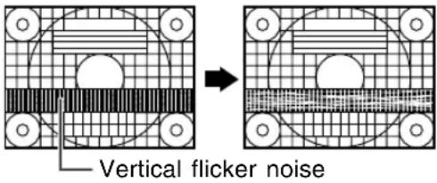 | |
| PHASE | Makes an adjustment after "CLOCK" is properly adjusted so that no horizontal flicker noise is emitted. |
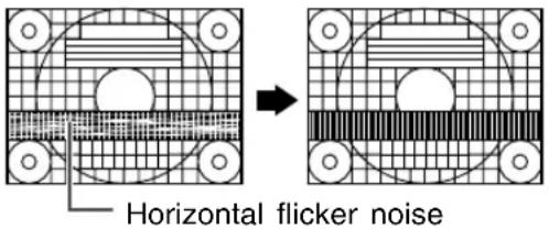 | |
| H-POS, V-POS | Adjusts the position of the adjustment pattern so that it appears centered on screen.Screen frame |
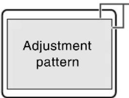 | |
| RESET | Resets adjustment values for this menu to their original factory settings. |
Note:
- To exit the adjustment program, press the computer's [Esc] key.
Using the menus in PC mode
GAIN CONTROL menu (See page E45 for information on using the menus.)
When using the TV with a digital connection, this menu adjustment is not necessary.
| Item | Description |
| AUTO | Automatically adjusts "BLACK LEVEL" and "CONTRAST" based on the brightest and darkest colors of the image displayed. |
| BLACK LEVEL | Adjust screen brightness watching the color pattern. ·Color pattern ·Color pattern |
| CONTRAST | Adjust contrast watching the color pattern so that all gradations appear. |
| RESET | Resets adjustment values for this menu to their original factory settings. |
Notes about auto adjustment:
- If you are not using the adjustment pattern, it is necessary to have black area and white area of at least 5 mm x 5 mm on the screen. Adjustment may not be possible without those areas.
- If the signal coming from the computer is Composite Sync or Sync on Green, automatic adjustment may not be possible. Please perform manual adjustment instead.
- If "OUT OF ADJUST" is displayed, perform manual adjustment. (To exit the adjustment program, press the computer's [Esc] key.)
AUDIO ADJUST menu (See page E45 for information on using the menus.)
When headphones are connected, the AUDIO ADJUST menu cannot be adjusted.
| Item | Description |
| TREBLE | Adjusts high-pitch sounds. |
| BASS | Adjusts low-pitch sounds. |
| BALANCE | Adjusts the balance between the right and left speakers. |
| DOLBY VIRTUAL | Turns the Virtual Dolby Surround function "ON" or "OFF".You can also set this item directly using the remote control, instead of the adjustment screen. (See page E29.) |
| RESET | Resets adjustment values for this menu to their original factory settings. |
Notes:
- "TREBLE", "BASS", and "BALANCE" can be adjusted only when "DOLBY VIRTUAL" is set to "OFF".
- Even in PC mode, the TV/AV mode's AUDIO ADJUST menu will appear when:
- Watching and listening to TV or video in the PIP/SPLIT window. (See pages E43 and E50.)
- Listening to the TV. (See pages E44 and E49.)
Using the menus in PC mode
COLOR CONTROL menu (See page E45 for information on using the menus.)
| Item | Description |
| COLOR MODE | Selects the color tone.- STD ...... Displays images using the original color tone of the LCD monitor.- sRGB ...... sRGB is an international standard for color representation defined by the IEC (International Electrotechnical Commission).Colors are converted by taking into account the liquid crystal's characteristics and thereby represent color tone close to the original image.- VIVID ...... Displays images in vivid primary colors. |
| WHITE BALANCE | Adjusts the color temperature.Set "WHITE BALANCE" to "STD" if you want to display all gradations.- COOL2 ...... Color tone bluer than standard.- COOL1 ...... Color tone slightly bluer than standard.- STD ...... Standard setting for color tone.- WARM1 ...... Color tone slightly redder than standard.- WARM2 ...... Color tone redder than standard.- USER ...... Allows you to individually adjust red, green, and blue contrast. |
| RESET | Resets adjustment values for this menu to their original factory settings. |
Note:
- "WHITE BALANCE" will be automatically set to "STD" when "COLOR MODE" is set to "sRGB" or "VIVID".
MODE SELECT menu (See page E45 for information on using the menus.)
| Item | Description |
| VIEW MODE | Selects the screen size.- NORMAL ...... Displays the image without changing its aspect ratio.When the image's resolution is lower than 1024 x 768, the image is expanded.- FULL...... Expands the image so that it fills the screen. (The aspect ratio may change.)You can also set this item directly using the remote control, instead of the adjustment screen. (See page E55) |
| 480 LINES | Specifies the horizontal resolution of a 480-line screen. (For analog signals)- 640 ...... 640 x 480 dot mode- 848 ...... 848 x 480 dot mode |
| 768 LINES | Specifies the horizontal resolution of a 768-line screen. (For analog signals)- 1024 ...... 1024 x 768 dot mode- 1280 ...... 1280 x 768 dot mode- 1360 ...... 1360 x 768 dot mode |
| SOUND | Selects the audio to listen to while displaying the computer screen.When the PIP/SPLIT window is displayed, the audio set by "SOUND" in the MULTI SCREEN menu takes precedence. (See page E50.)When "STATUS" in the V-CHIP BLOCK menu is "ON" (see page E37), TV/AV-IN SOUND is not available in PC mode. |
| SCALING | Adjusts the image to optimum sharpness when it is enlarged. |
| LANGUAGE | Selects the language (English, Spanish, or French) on the screen.(See page E30.) |
| RESET | Resets adjustment values for this menu to their original factory settings. |
Using the menus in PC mode
MULTI SCREEN menu (See page E45 for information on using the menus.)
| Item | Description |
| MULTI SCREEN DISPLAY | Designates whether the computer screen and TV or video images are displayed simultaneously.- OFF- PIP ...... The TV or video image appears in a small window (PIP window) on the computer screen.- SPLIT ...... The computer screen and the TV or video image appear side by side in two split windows.You can also set this item directly using the remote control, instead of the adjustment screen. (See page E43.) |
| PIP SIZE | Changes the size of the PIP window. |
| PIP POSITION | Adjusts the position of the PIP window.To move up and down, press the ▲▼ buttons.To move left and right, press the ◀▶ buttons.While displaying the PIP window, you can also set this item directly using the remote control, instead of the adjustment screen. (See page E43.) |
| PC POSITION | Designates the position of the computer screen when the PIP window is displayed.This item is enabled when the computer's "VIEW MODE" is set to "NORMAL". |
| SUB SOURCE | Selects the video source of the PIP/SPLIT window. |
| SOUND | Selects the audio you want to hear while displaying the PIP/SPLIT window.- PC ...... Computer audio- SUB SOURCE ... TV or video audio |
| RESET | Resets adjustment values for this menu to their original factory settings. |
Note:
- "PIP SIZE", "PIP POSITION", and "PC POSITION" can only be set when "MULTI SCREEN DISPLAY" is set to "PIP".
Installing set-up information and the ICC profile (For Windows)
Depending on the type of computer or OS, you may need to install the monitor set-up information on your system. If so, follow the steps below to install the monitor set-up information. (Depending on the type of computer or OS, command names and methods may differ. Please follow the computer's own operation manual while reading this.)
About the ICC profile
An ICC (International Color Consortium) profile is a file that describes the color reproduction characteristics of the LCD monitor. Using an application compatible with an ICC profile, highly accurate color reproduction can be realized.
- Windows 98/2000/Me/XP all use the ICC profile.
- When installing Windows 98/2000/Me/XP set-up information (described below), the ICC profile is also installed. If you would like to install the ICC profile only, please refer to Installing the ICC profile on page E53.
- When using the ICC profile, set "COLOR MODE" and "WHITE BALANCE" to "STD".
For Windows 95
Installing monitor set-up information into Windows 95.
This explanation assumes that the CD-ROM drive is "D" drive.
- Load the supplied CD-ROM into the CD-ROM drive of the computer.
- Click on the [Start] button. From [Settings], choose [Control Panel].
- Double click on [Display].
- Click on [Settings], [Advanced Properties], and [Monitor], then [Change].
- Click on [Have disk], confirm that [Copy manufacturer's files from:] is [D:] then click [OK].
- Confirm that the monitor details are selected, and click [OK].
- Check that the monitor details are displayed, then click [Apply].
- Click [OK], and close the window.
- Eject the CD-ROM from the CD-ROM drive.
For Windows 98
Installing monitor set-up information into Windows 98, and setting the monitor's ICC profile as a predetermined value.
This explanation assumes that the CD-ROM drive is "D" drive.
If the "Add New Hardware Wizard" has appeared:
-
Load the supplied CD-ROM into the CD-ROM drive of the computer.
-
Click [Next].
-
Check [Display a list of all the drivers in a specific location, so you can select the driver you want.], then click [Next].
-
When [Models] is displayed, click on [Have disk], confirm that [Copy manufacturer's files from:] is [D:], and click [OK].
-
Confirm that the monitor details are selected, then click [Next], [Next], and [Finish]. If the "Add New Hardware Wizard" appears, repeat the installation commands beginning from 2 above.
-
Eject the CD-ROM from the CD-ROM drive.
If the "Add New Hardware Wizard" has not appeared:
- Load the supplied CD-ROM into the CD-ROM drive of the computer.
- Click on the [Start] button. From [Settings], choose [Control Panel].
- Double click on [Display].
- Click on [Settings], [Advanced], and [Monitor].
- In [Options], check [Automatically detect Plug & Play monitors] and click on [Change].
- Click [Next].
- Click on [Display a list of all the drivers in a specific location, so you can select the driver you want.], then click [Next].
- When [Models] is displayed, click on [Have disk], confirm that [Copy manufacturer's files from:] is [D:], and click [OK].
- Confirm that the monitor details are selected, then click [Next], [Next], and [Finish].
- Check that the monitor details are displayed, then click [Apply].
- Click [OK], and close the window.
- Eject the CD-ROM from the CD-ROM drive.
Installing set-up information and the ICC profile (For Windows)
For Windows 2000
Installing monitor set-up information into
Windows 2000, and setting the monitor's ICC profile as a predetermined value.
This explanation assumes that the CD-ROM drive is "D" drive.
- Load the supplied CD-ROM into the CD-ROM drive of the computer.
- Click on the [Start] button. From [Settings], choose [Control Panel].
- Double click on [Display].
- Click on [Settings], [Advanced], and [Monitor].
- Click on [Properties], [Driver], and [Update Driver].
- When [Upgrade Device Driver Wizard] appears, click [Next].
- Check [Display a list of the known drivers for this device so that I can choose a specific driver] and click [Next].
- When [Models] is displayed, click on [Have disk], confirm that [Copy manufacturer's files from:] is [D:], and click [OK].
- Select the monitor from the list displayed and click [Next].
- Click [Next], confirm that the monitor's name appears on the screen, and click [Finish]. If [The Digital Signature Not Found] appears, click [Yes].
- Click on [Close].
- Click [OK], and close the window.
- Eject the CD-ROM from the CD-ROM drive.
For Windows Me
Installing monitor set-up information into Windows Me, and setting the monitor's ICC profile as a predetermined value.
This explanation assumes that the CD-ROM drive is "D" drive.
If the "Add New Hardware Wizard" has appeared:
- Load the supplied CD-ROM into the CD-ROM drive of the computer.
- Check [Specify the location of the driver [Advanced]] and click [Next].
- Check [Display a list of all the drivers in a specific location, so you can select the driver you want.], then click [Next].
- When [Models] is displayed, click on [Have disk], confirm that [Copy manufacturer's files from:] is [D:], and click [OK].
- Select the monitor details from the list, then click [Next], [Next], and [Finish]. If the "Add New Hardware Wizard" appears, repeat the installation commands beginning from 2 above.
- Eject the CD-ROM from the CD-ROM drive.
If the "Add New Hardware Wizard" has not appeared:
- Load the supplied CD-ROM into the CD-ROM drive of the computer.
- Click on the [Start] button. From [Settings], choose [Control Panel].
- Double click on [Display].
- Click on [Settings], [Advanced], and [Monitor].
- In [Options], check [Automatically detect Plug & Play monitors] and click on [Change].
- Check [Specify the location of the driver [Advanced]] and click [Next].
- Check [Display a list of all the drivers in a specific location, so you can select the driver you want.] and click [Next].
- When [Models] is displayed, click on [Have disk], confirm that [Copy manufacturer's files from:] is [D:], and click [OK].
- Select the monitor details, then click [Next], [Next], and [Finish].
- Check that the monitor details are displayed, then click [Apply].
11.Click [OK], and close the window. - Eject the CD-ROM from the CD-ROM drive.
Installing set-up information and the ICC profile (For Windows)
For Windows XP
Installing monitor set-up information into Windows XP, and setting the monitor's ICC profile as a predetermined value.
This explanation assumes that the CD-ROM drive is "D" drive.
- Load the supplied CD-ROM into the CD-ROM drive of the computer.
- Click on the [Start] button. Choose [Control Panel].
- Click on [Appearance and Themes] and [Display]. When using the Classic View, double click on [Display].
- Click on [Settings], [Advanced], and [Monitor].
- Click on [Properties], [Driver], and [Update Driver]. [Hardware Update Wizard] appears. When you are asked whether to search Windows Update for the device driver, check [No, not this time] and click [Next].
- Check [Install from a list or specific location [Advanced]] and click [Next].
- Check [Don't search. I will choose the driver to install.] and click [Next].
- Click on [Have Disk], confirm that [Copy manufacturer's files from:] is [D:], and click [OK].
- Select the monitor from the list displayed and click [Next]. If [has not passed Windows Logo testing...] appears, click [Continue Anyway].
- Confirm that the monitor's name appears on the screen.
- Click on [Finish].
- Click on [Close].
- Click [OK], and close the window.
- Eject the CD-ROM from the CD-ROM drive.
Installing the ICC profile
Installing the monitor's ICC profile. (If the set-up information has already been installed, so too has the profile, and there is no need to install it.)
- Load the supplied CD-ROM into the CD-ROM drive of the computer.
- Click on the [Start] button. From [Settings], choose [Control Panel].
- Double click on [Display]. When using the Category View on Windows XP, click on [Appearance and Themes] and [Display].
- Click on [Settings] and [Advanced].
- Click on [General] and from [Compatibility] select [Apply the new display setting without restarting], then click on [Color Management].
- Click [Add], and select CD-ROM as the file location.
- Choose the color profile that you would like to install, and click on [Add].
- Choose the profile and click on [Set As Default].
- Click [OK], and close the window.
- Eject the CD-ROM from the CD-ROM drive.
- When using the ICC profile, set "COLOR MODE" and "WHITE BALANCE" to "STD".
Information about the ColorSync profile (For MacOS)
About the ColorSync profile
ColorSync is Apple Computer's color management system and enables color reproduction characteristics to be realized when used with a compatible application. A ColorSync profile describes the color characteristics of the LCD monitor.
Notes:
- This monitor's ColorSync profile works with MacOS 8.5 or above.
- When using the ColorSync profile, set "COLOR MODE" and "WHITE BALANCE" to "STD".
Setting up the ColorSync profile
Notes:
- It is necessary to have PC Exchange or File Exchange installed in your system.
-
Depending on the type of computer or OS, command names and methods may differ. Please follow the computer's own operation manual while reading this.
-
Load the supplied CD-ROM into the CD-ROM drive of the computer.
- Copy the profile to be used from the CD-ROM to the ColorSync profile folder.
- Using the ColorSync on the control panel, choose the profile to be used.
Changing the screen size (VIEW MODE)
You can change the screen size to match the video on videotapes and DVDs.
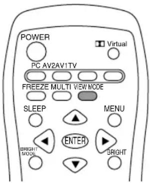
[TV/AV mode]
- Press the VIEW MODE button.
The mode switches in the following order each time you press the button:
$$ \begin{array}{l} \text {NORMAL} \to \text {WIDE} \to \text {ZOOM1} \to \text {ZOOM2} \to \ \text {FULL} \to \text {NORMAL...} \end{array} $$
NORMAL Displays 4:3 aspect ratio TV images normally.
WIDE Expands 4:3 images horizontally to fill the entire screen (16:9).
ZOOM1 Expands the image to fill the screen (16:9) with wide black bands across the top and bottom such as letterbox format movies.
ZOOM2 Can be used when "ZOOM1" cuts off captions or telops at the top or bottom of the screen.
FULL Returns images horizontally reduced from 16:9 to 4:3 back to 16:9 so they fill the entire screen.
[PC mode]
- Press the VIEW MODE button.
The mode switches in the following order each time you press the button: NORMAL → FULL → NORMAL...
NORMAL Displays the image without changing its aspect ratio. When the image's resolution is lower than 1024 x 768, the image is expanded.
FULL Expands the image so that it fills the screen. (The aspect ratio may change.)
Notes:
- Depending on the type of data received or the video software used, screen edges may be slightly cut off or the image may have a black border.
- You can also change the screen size using the menus. (See pages E42 and E49.)
- The screen size cannot be changed while an image is paused. (See page E39.)
- The screen size cannot be changed when video signals of 1080i or 720p are input externally. The images are displayed in the ratio of 16:9.
- Be aware that the use of screen resize functions to enlarge/reduce images for profit or for public display may infringe on copyright protection provided under Copyright Law.
Checking the current channel and audio mode on screen (DISPLAY)
You can check your TV's current display mode, type of PC input terminal, TV channel, MTS mode, time remaining on the SLEEP timer, and other items.
- Press the DISPLAY button.
Various information about the current state will be displayed.
10
STEREO
The information will disappear after several seconds.
Notes:
- The information displayed will vary depending on the current display mode and other settings.
- If the TV broadcast changes while the information is displaying, the broadcast and MTS mode may not match.
Other features
Muting the sound (MUTE)
This feature is handy when you want to mute the sound such as when the phone rings or someone comes to the door.
- Press the MUTE button.
The sound will be muted and "MUTE" will be displayed.
"MUTE" will disappear after several seconds.
Canceling muting
- Press the MUTE button again, or press the VOL buttons.
Changing BRIGHT MODE
You can lower energy consumption by decreasing screen brightness. If "OFF" is selected, images will disappear and only sound will be output.
- Press the BRIGHT MODE button.
The mode changes in the following order each time you press the button:
BRIGHT → DARK1 → DARK2 → OFF → BRIGHT...
Notes:
- You can set screen brightness individually for PC mode and TV/AV mode.
- You can set screen brightness using the ENTER/BRIGHT MODE button on the TV.
- While "BRIGHT MODE" is set to "OFF", you can operate MTS, MUTE, Dolby Virtual, and VOL buttons on the remote control. However, an adjustment screen will not be displayed. And when you operate the other buttons, the display will be turned on with the mode "BRIGHT".
Preventing changes to adjusted values (ADJUSTMENT LOCK)
Disabling the control buttons other than the following buttons (TV and remote control) prevents adjusted values from being changed.
The changing of adjusted values for both PC mode and TV/AV mode will be prevented.
[TV]
- POWER button
- VOL/BRIGHT buttons
- INPUT button
- CH buttons
[Remote control]
- POWER button
- VOL buttons
- MUTE button
- Input buttons (PC, TV, AV1, and AV2)
- CH buttons
- Channel buttons (0-9 and 100)
- FLASHBACK button
Perform this procedure on the TV.
- Turn off the TV power.
-
While pressing the MENU button, press the POWER button (i.e. turn the power on). Continue to press the buttons until "LOCK ADJUSTMENT?" appears on the screen.
-
Press the VOL/BRIGHT > button.
Releasing the adjustment lock
Perform this procedure on the TV.
- Turn off the TV power.
-
While pressing the MENU button, press the POWER button (i.e. turn the power on).
Continue to press the buttons until "UNLOCK ADJUSTMENT?" appears on the screen. -
Press the VOL/BRIGHT > button.
CAUTION!
- When the adjustment lock is set, all buttons on the TV and remote control other than the above buttons are disabled. To use buttons other than the above buttons, release the adjustment lock.
Resetting all adjustment values (ALL RESET)
All adjustment values will be reset for both PC mode and TV/AV mode (including channel settings and the secret number for V-chip Block).
Concerning the ALL RESET procedure, refer to the end of this manual.
Instructions for attaching a VESA-compliant mount
An arm or stand based on the VESA standard (commercially available) can be attached to the TV. Procurement of the arm or stand is at the customer's discretion.
Arms or stands able to be used
Attachments must satisfy the following.
- Compatible with the VESA standard.
- The six screw holes on the section to be attached have a gap of 100 mm between them.
- Not be likely to fall off or break off after being attached to the TV.
How to attach the arm or stand
- Be careful not to over bend the cable or add extension cords as this could lead to a malfunction.
- While following these instructions, please also refer to the installation instructions in the operation manual included with the arm or stand.
CAUTION!
- Be careful not to get your fingers pinched between the display and stand nor to let the stand drop. These could lead to injury.
-
Do not cover or block the vents and openings since insufficient ventilation can cause overheating.
-
Remove the cables.
- Spread out a soft cloth on a flat surface. Being careful not to damage the TV, gently lay the TV on it display-side down.
- Remove the two screws and then remove the rear cover of the stand.
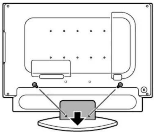
natural_image
Diagram of a computer monitor with an open screen and a button, showing no text or symbols- Remove the six screws and then remove the stand from the TV.
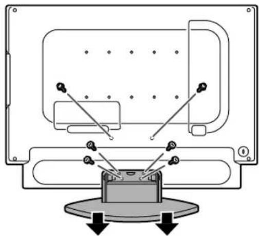
natural_image
Technical diagram of a mechanical assembly with labeled components and directional arrows (no text or symbols)Notes:
- The stand is specially made for use with this TV. Once having removed the stand, never attempt to attach it to another equipment.
-
Once having removed the screws, store them together with the stand. If the stand is ever reattached, be sure to use the original screws. Using different screws could lead to a malfunction.
-
Attach the arm to the TV with the six screws.
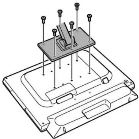
natural_image
Technical line drawing of a mechanical assembly with pins and components (no text or symbols)Note:
- The screws used to attach the arm should be M4 screws with a length of 6 mm - 8 mm protruding from the surface to be attached. Using different screws could cause the TV to fall off or to be internally damaged.
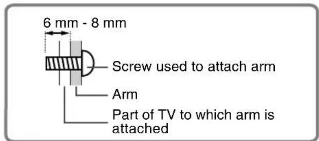
- Reconnect the cables.
Troubleshooting
If you think the TV may be faulty, please check the following points before taking it to be repaired. If afterwards it still does not work, please contact the shop where you purchased the TV or your nearest Sharp authorized Service Center.
The TV's fluorescent tubes have a limited life span.
- If the screen darkens, persistently flickers or does not light up, the fluorescent tube has reached the end of its operational life span. Please inquire at the shop where you purchased the TV or your nearest Sharp authorized Service Center.
- In the initial period of use, due to the characteristics of fluorescent tubes the screen may flicker. (This is not a malfunction.) Should this happen, check by first turning off the power, then turning it on again.
| Problem | What to Check |
| There is no picture.(Power LED does not light.) | - Are the AC adapter and power cord properly connected? Disconnect the power plug from the AC outlet and reconnect it again. (Page E22)- Is power turned on? (Page E27) |
| There is no picture.(Power LED is lit orange.) | - Is the TV properly connected to the computer? (Pages E20 and E21)- Is the computer turned on?- Is the PC signal input terminal (analog or digital) properly selected? (Page E27)- Does the computer's signal timing correspond to TV specifications? (Page E61)- Is the computer in power-saving mode?Try pressing a key on the keyboard or moving the mouse. |
| The image appears distorted. | - Does the computer's signal timing correspond to TV specifications? (Page E61)- If you are using the analog signal, perform automatic screen adjustment. (Page E26)- Change the Vsync frequency (refresh rate) on the computer you are using to a low value if possible. (Page E61) |
| The remote control does not work. | - Have the batteries of the remote control run out? (Page E13)- Are the batteries placed in the right direction in the remote control? (Page E13)- Is the adjustment lock set? (Page E56) |
| There is no TV picture. | - Is the TV connected to an antenna? Check the connection.(Pages E16 and E17)- Is the TV switched to TV mode? (Page E27)- Have you set TV channels properly? (Pages E23 to E25)- Did you set "BRIGHT MODE" to "OFF"? (Page E56) |
| A particular channel will not tune in. | - Have you set TV channels properly? (Pages E23 to E25) |
| There are stripes or dots on TV picture.The picture wavers. | - Is there interference from automobiles, trains, neon signs, computers, or other sources?- Place the antenna as far as possible away from potential sources of interference.- Place the antenna line as far as possible from the computer. |
| The TV picture is doubled. | - Is the antenna facing the right direction?There may be reflected electric waves from nearby mountains or buildings. Try changing the antenna's height and direction. |
| There are color bands. | - Is there interference from a nearby TV?Changing the antenna's height and direction may help. |
| The TV picture is distorted. | - Try switching power off, waiting several seconds, and then turning power back on. |
TV care
| Problem | What to Check |
| There is no video picture.There is no game picture. | - Are the cables properly connected? (Pages E18 and E19)- Have you switched to AV mode? (Page E27)- Did you set "BRIGHT MODE" to "OFF"? (Page E56)- Have you turned on the connected equipment? |
| The TV picture does not move.The video picture does not move. | - Is the screen pausing? Did you press the FREEZE button?(Page E39) |
| There is no sound. | - Are the audio cables properly connected? (Pages E18, E19 and E21)- Did you press the MUTE button? (Page E56)- No sound can be heard from the TV speakers while headphones are connected.- Adjust the volume. (Page E29)- No sound can be heard from the TV speakers while the TV is in power-saving mode.- When "STATUS" in the V-CHIP BLOCK menu is "ON", TV/AV-IN SOUND is not available in PC mode. (Pages E37 and E44) |
| Control buttons do not work.The adjustment screen does not appear. | - Is the adjustment lock set? (Page E56) |
| Control buttons do not work.The remote control does not work.There is no picture. | Some kind of load noises from outside might interfere with normal operation.- Turn off the power and turn it on after waiting at least 5 seconds, and then check the operation.- If the problem cannot be solved, disconnect and reconnect the power plug from/to the AC outlet and check the operation. |
TV care
Always remove the plug from the AC outlet when cleaning the TV.
Cabinet and control panel section
Use a soft dry cloth to lightly wipe away any grime from the cabinet and control panel.
If they are very dirty, apply neutral detergent to a dampened soft cloth, wring it out well and wipe away grime.
LCD panel section
Use a soft dry cloth to lightly wipe away dirt and dust from the surface of the LCD panel. (A soft cloth such as gauze or that used for lens cleaning is suitable.)
CAUTION!
- Never use thinner, benzine, alcohol, glass cleaner, etc., as this could lead to color change or change in shape.
- Never scratch the TV with anything hard or apply strong pressure as this could leave marks or result in malfunction.
Storage
If the TV will not be used for a long period of time, be sure to remove the power plug from the AC outlet.
CAUTION!
- Do not leave the TV in contact with rubber or plastic items for long periods of time as this could lead to color change or change in shape.
Specifications
Product specifications
Model name
LD-23SH1U
LCD display
23" TFT LCD module
Actual display size
23" (58.3 cm) measured diagonally
Resolution (max.)
1366 x 768
Displayable colors (max.)
Approx. 16.77 million colors (8 bit)
Dot pitch (H x V)
0.372 mm x 0.372 mm
Brightness (max.)
500 cd/m²
(The screen brightness deteriorates over time.
Constant brightness cannot be maintained.)
Contrast ratio
550:1
Angle of visibility
Left-right 176°; up-down 176°
(contrast ratio > 10)
Screen display size (H x V)
508.2 mm x 285.7 mm
Video signal
Analog: Analog RGB (0.7 Vp-p) [75Ω]
Digital: DVI standard based on 1.0
Sync signal
Separate Sync (TTL level: +/-), Sync on Green,
Composite Sync (TTL level: +/-)
Video signal format
NTSC
Expansion compensation
Digital scaling (Enlarges VGA/SVGA/XGA etc. to full screen size.)
[Enlarged display (full screen, fixed aspect ratio)]
- 1:1 display is not possible.
Plug & Play
VESA DDC2B compatible
Power management
VESA: based on DPMS
DVI: based on DMPM
Speaker output
5 W + 5 W
Input terminals
Video image: RCA pin x 2
Component image: x 1
S-video image: x 1
Audio: RCA pin (L/R x 2)
Antenna: F-type
Computer signal:
Digital: DVI-D 24 pin x 1
Receivable TV channels
VHF: 2 through 13; UHF: 14 through 69;
Cable: 1 through 125
Headphone terminal
Mini stereo jack (φ 3.5 mm)
Screen tilt
Upward approx. 0° - 20°; downward approx. 0° - 5°
Screen swivel
Approx. 90° from left through right
Power supply
100 VAC - 240 VAC, 50/60 Hz (Uses special AC adapter, type NL-A72J of Sharp Corporation)
Temperature of operating environment
5^ - 35^ (41^ - 95^)
Power consumption
95 W ^* ; 5.5 W in standby; 5.5 W in power-saving mode
*When "BRIGHT MODE" is set to "BRIGHT".
62 W in "DARK1" and 52 W in "DARK2".
(Uses special AC adapter)
Dimensions (W x D x H)
Approx. 589 mm x 223 mm x 479 mm
(Approx. 23^13 / 64'' × 8^25 / 32'' × 18^55 / 64'' )
Weight
Approx. 13 kg; 28.7 lb. (excluding signal cable
and AC adapter)
Approx. 10.2 kg; 22.5 lb. (excluding stand)
Dimensions (Units: mm (inch))
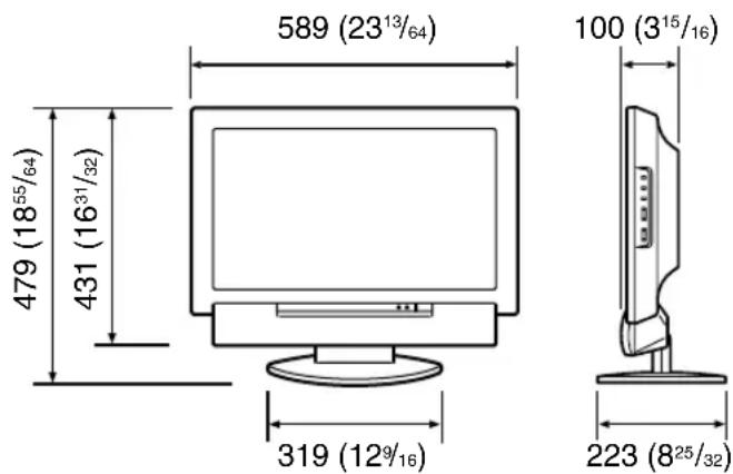
- PC analog signal cable: approx. 1.8 m (5' 10")
- PC audio cable: approx. 1.8 m (5' 10")
- Antenna cable: approx. 4 m (13' 1")
- Digital signal cable, NL-C04J (purchased separately): approx. 2.0 m (6' 6")
- Special AC adapter:
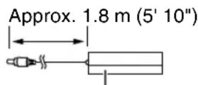
Dimensions (W x D x H)
Approx. 170 mm x 85 mm x 40 mm
(Approx. 6^45 / 64'' × 3^23 / 64'' × 1^37 / 64'' )
Specifications
Note:
- As a part of our policy of continuous improvement, SHARP reserves the right to make design and specification changes for product improvement without prior notice. The performance specification figures indicated are nominal values of production units. There may be some deviations from these values in individual units.
Relevant signal timings (PC mode)
| Screen resolution | Hsync Vsync | Dot frequency | Analog Digital | |||
| VESA | 640x480 | 31.5kHz | 60Hz | 25.175MHz | ○ | ○ |
| 37.9kHz | 72Hz | 31.5MHz | ○ | ○ | ||
| 37.5kHz | 75Hz | 31.5MHz | ○ | ○ | ||
| 800x600 | 35.1kHz | 56Hz | 36.0MHz | ○ | - | |
| 37.9kHz | 60Hz | 40.0MHz | ○ | ○ | ||
| 48.1kHz | 72Hz | 50.0MHz | ○ | ○ | ||
| 46.9kHz | 75Hz | 49.5MHz | ○ | ○ | ||
| 1024x768 | 48.4kHz | 60Hz | 65.0MHz | ○ | ○ | |
| 56.5kHz | 70Hz | 75.0MHz | ○ | ○ | ||
| 60.0kHz | 75Hz | 78.75MHz | ○ | ○ | ||
| Wide | 848x480 | 31.1kHz | 60Hz | 33.3MHz | ○ | - |
| 1280x720 | 44.7kHz | 60Hz | 74.4MHz | ○ | - | |
| 1280x768 | 47.986kHz | 60Hz | 81.0MHz | ○ | ○ | |
| 60.15kHz | 75Hz | 102.977MHz | ○ | - | ||
| 1360x768 | 47.7kHz | 60Hz | 84.7MHz | ○ | - | |
| US text | 720x400 | 31.5kHz | 70Hz | 28.3MHz | ○ | ○ |
| Power Macintosh series | 640x480 | 35.0kHz | 66.7Hz | 30.2MHz | ○ | - |
| 832x624 | 49.7kHz | 74.6Hz | 57.3MHz | ○ | - | |
| 1024x768 | 60.2kHz | 75Hz | 80.0MHz | ○ | - | |
- Recommended resolution is 1360 x 768, 1280 x 768, or 1024 x 768.
- All are compliant only with non-interlaced.
- Depending on the type of computer to be connected, the display may not work correctly even when the above relevant signals are input.
- Frequencies for Power Macintosh are reference values. To connect, another adapter (commercially available) may be required.
- For digital connection, the TV can be connected to a computer with a DVI-compatible output terminal (DVI-D 24 pin or DVI-I 29 pin). (Depending on the type of computer to be connected, the display may not work correctly.)
- If the TV is receiving timing signals that are not compatible, "OUT OF TIMING" will appear. Follow your computer's operation manual to set the timing so that it is compatible with the TV.
- If the TV is not receiving any signal (sync signal), "NO SIGNAL" will appear.
Specifications
The analog RGB input connector pin
(Mini D-sub connector with 15 pins)
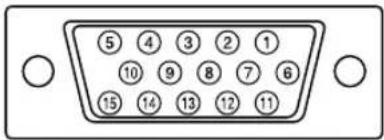
| No. | Function |
| 1 Red video signal input | |
| 2 Green video signal input | |
| 3 Blue video signal input | |
| 4 N.C. | |
| 5 GND | |
| 6 For red video signal GND | |
| 7 For green video signal GND | |
| 8 For blue video signal GND | |
| 9 | +5V |
| 10 | GND |
| 11 | N.C. |
| 12 | DDC data |
| 13 | For Hsync signal input |
| 14 | For Vsync signal input |
| 15 | DDC clock |
The DVI-D input connector pin
(DVI-D connector with 24 pins)
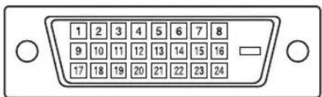
| No. | Function | No. | Function |
| 1 | TMDS data 2- | 13 | N.C. |
| 2 | TMDS data 2+ | 14 | +5V |
| 3 | TMDS data 2/4 shield | 15 | GND |
| 4 | N.C. | 16 | Hot plug detection |
| 5 | N.C. | 17 | TMDS data 0- |
| 6 | DDC clock | 18 | TMDS data 0+ |
| 7 | DDC data | 19 | TMDS data 0/5 shield |
| 8 | N.C. | 20 | N.C. |
| 9 | TMDS data 1- | 21 | N.C. |
| 10 | TMDS data 1+ | 22 | TMDS clock shield |
| 11 | TMDS data 1/3 shield | 23 | TMDS clock + |
| 12 | N.C. | 24 | TMDS clock - |
Power management
The monitor is based on the VESA DPMS and the DVI DMPM standards. To activate the power management function, the video card and the computer used with it must also conform to these standard.
DPMS: Display Power Management Signaling
| DPMS mode | Screen | Power consumption | H-sync | V-sync |
| ON Display on 95 W Yes | Yes | |||
| STANDBY No Yes | W Yes No | |||
| SUSPEND D | splay off 5.5 | |||
| OFF No | No | |||
DMPM: Digital Monitor Power Management
| DMPM mode | Screen | Power consumption |
| ON | Display on 95 W | |
| OFF | Display off | 5.5 W |
DDC (Plug & Play)
This monitor supports the VESA DDC (Display Data Channel) standard.
DDC is a signal standard for carrying out Plug & Play functions on the monitor or computer. It transfers information such as degree of resolution between the monitor and computer. You can use this function if your computer is DDC compliant and if it is set so that it can detect the Plug & Play monitor.
There are many varieties of DDC due to the differences between systems. This monitor works with DDC2B.