CL608NX - Label printer SATO - Free user manual and instructions
Find the device manual for free CL608NX SATO in PDF.

User questions about CL608NX SATO
0 question about this device. Answer the ones you know or ask your own.
Ask a new question about this device
Download the instructions for your Label printer in PDF format for free! Find your manual CL608NX - SATO and take your electronic device back in hand. On this page are published all the documents necessary for the use of your device. CL608NX by SATO.
USER MANUAL CL608NX SATO
natural_image
Line drawing of a rice cooker with control panel and door (no text or symbols)Copyrights
Any unauthorized reproduction of the contents of this document, in part or whole, is strictly prohibited.
Limitation of Liability
SATO Corporation and its subsidiaries in Japan, the U.S. and other countries make no representations or warranties of any kind regarding this material, including, but not limited to, implied warranties of merchantability and fitness for a particular purpose. SATO Corporation shall not be held responsible for errors contained herein or any omissions from this material or for any damages, whether direct, indirect, incidental or consequential, in connection with the furnishing, distribution, performance or use of this material.
Specifications and contents in this document are subject to change without notice.
Be sure to perform a virus check for the USB memory before connecting it to the printer. SATO Corporation shall not be held responsible for a malfunction of the printer caused by a virus infection through the USB memory.
Trademarks
SATO is a registered trademark of SATO Holdings Corporation and its subsidiaries in Japan, the U.S. and other countries.
QR Code is a registered trademark of DENSO WAVE INCORPORATED.
Wi-Fi ^® is a registered trademark of Wi-Fi Alliance.
Wi-Fi Direct™, Wi-Fi Protected Setup™, WPA™ and WPA2™ are trademarks of Wi-Fi Alliance.
Cisco, the Cisco logo, and Cisco Systems are trademarks or registered trademarks of Cisco Systems, Inc. and/or its affiliates in the United States and certain other countries.
Bluetooth is a trademark of Bluetooth SIG, Inc., U.S.A.
ENERGY STAR and ENERGY STAR mark are registered U.S. marks.
ICODE, I-CODE, and SLI are registered trademarks of NXP B.V.
MIFARE ^® is a registered trademark of NXP B.V.
Tag-it™ is a trademark of Texas Instruments.
my-d ^TM is a registered trademark of Infineon Technologies AG.
FeliCa is a registered trademark of Sony Corporation.
FeliCa is a contactless IC card technology developed by Sony Corporation.
All other trademarks are the property of their respective owners.
Table of Contents
Table of Contents 1
Before You Start.... 5
Features of the Product.... 5
Safety Precautions.... 6
Precautions for Installation and Handling 9
Regulatory Approval.... 10
1 Parts Identification.... 13
1.1 Parts Identification of the Printer 13
1.1.1 Front View 13
1.1.2 Rear View 14
1.1.3 Internal View.... 15
1.2 Parts on the Operator Panel.... 16
1.2.1 Operator Panel 16
1.2.2 LED Indicator 17
2 Installing the Printer 19
2.1 Installation Precautions.... 19
2.2 Installation Space.... 20
2.2.1 Front View (CL4NX) 20
2.2.2 Front View (CL6NX) 20
2.2.3 Side View (CL4NX/CL6NX) 21
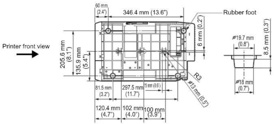
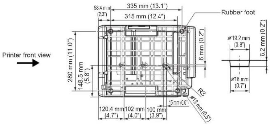
2.2.4 Bottom View (CL4NX) 22
2.2.5 Bottom View (CL6NX) 22
2.3 Checking the Bundled Accessories 23
2.4 Connecting the Interface Cable 24
2.4.1 Available Interfaces 24
2.4.2 Interface Settings.... 24
2.5 Connecting the Power Cord 25
2.6 Power On/Off the Printer 26
2.6.1 Power On the Printer 26
2.6.2 Power Off the Printer 27
2.7 Starting Up the Printer (Startup Guide).... 28
2.7.1 Startup Screen.... 28
2.7.2 Language Selection.... 28
2.7.3 Region Setting with Optional RTC 29
2.7.4 City Setting with Optional RTC 29
2.7.5 Date Setting with Optional RTC 29
2.7.6 Time Setting with Optional RTC 30
2.7.7 Print Method Setting 30
2.7.8 Ribbon Setting 31
2.7.9 Setting the Media Sensor Type 31
2.7.10 Media Setting.... 32
2.7.11 Confirmation Screen 33
2.7.12 Startup Guide Cancelation 33
3 Loading the Ribbon and Media.... 35
3.1 Checking the Ink Side of the Ribbon.... 35
3.2 Loading the Ribbon 36
3.3 Removing the Ribbon 39
3.4 Usable Media 40
3.4.1 Adjusting the Position of the Media Sensor.... 40
3.5 Loading Media 41
3.5.1 Loading Media Roll 41
3.5.2 Loading Fan-fold Media 43
3.5.3 Loading Media with the Optional Cutter 44
3.5.4 Loading Media with an Optional Dispenser and Liner Discharge Outlet 44
3.5.5 Loading Media with an Optional Dispenser and Liner Rewinder 45
3.5.6 Removing the Liner from the Rewinder 47
4 Operation and Configuration.... 49
4.1 Display and Operation 49
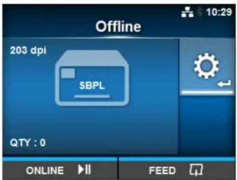
4.1.1 Online Mode/Offline Mode 49
4.1.2 Status Icon.... 50
4.1.3 Error Icon.... 53
4.1.4 Guidance Video 56
4.1.5 How to Adjust the Print Settings During Printing 59
4.1.6 How to Cancel the Print Job 60
4.2 Settings Mode.... 61
4.2.1 Changing to Settings Mode 61
4.2.2 Log In to/Log Out of the Settings Mode 62
4.2.3 Item Selection.... 63
4.2.4 Setting Value Input or Selection 64
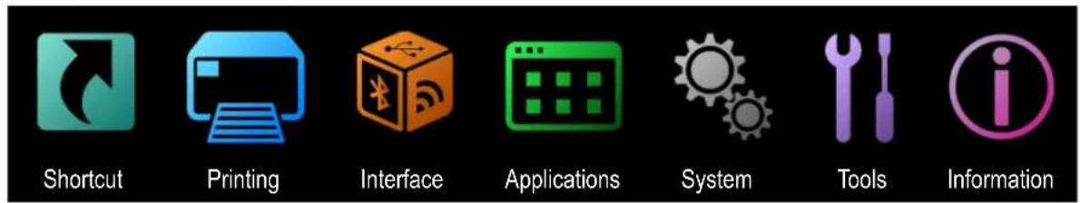
4.3 Settings Menu Tree Structure 67
4.4 Details of the Settings Menu Screen 81
4.4.1 Shortcut Menu 81
4.4.2 Printing Menu 82
4.4.3 Interface Menu.... 103
4.4.4 Applications Menu 170
4.4.5 System Menu.... 188
4.4.6 Tools Menu.... 199
4.4.7 Information Menu.... 220
4.5 Web Configuration 230
4.5.1 Dashboard 230
4.5.2 Settings.... 231
4.5.3 Tools 233
4.5.4 Certificates.... 235
5 Cleaning and Performing Printer Adjustments 237
5.1 Maintenance 237
5.2 Maintenance of the Print Head and Platen Roller 238
5.2.1 Maintenance using the Cleaning Kit 238
5.2.2 Additional Procedure for the Optional Linerless Kit (CL4NX only) 241
5.2.3 Maintenance using the Cleaning Sheet 242
5.3 Adjusting the Base Reference Point 244
5.3.1 About the Base Reference Point 244
5.3.2 Adjusting the Print Position.... 245
5.3.3 Adjusting the Media Stop Position.... 247
5.3.4 Notes on the Stop/Cut Position of Different Media 248
5.4 Adjusting the Print Quality.... 250
5.4.1 Adjustment of the Print Darkness 250
5.4.2 Adjusting the Print Speed 251
5.5 Adjusting the Buzzer Volume 253
5.6 Adjusting the Head Pressure Balance 254
5.6.1 Head Pressure Setting 254
5.6.2 Pressure Balance Setting 255
6 Troubleshooting.... 257
6.1 When an Error Message Occurs.... 257
6.1.1 More Information about Command Error.... 264
6.2 When the LED Lights Red/Blue 266
6.3 Troubleshooting Table 267
6.3.1 No Power/Nothing on the Screen 267
6.3.2 Cannot Feed the Media 267
6.3.3 Can Feed the Media but Cannot Print 268
6.3.4 Bad Print Quality 269
6.3.5 Incorrect Print Position 270
6.4 Interface Troubleshooting.... 271
6.4.1 USB Interface 271
6.4.2 LAN Ethernet Interface 271
6.4.3 Bluetooth Interface 271
6.4.4 RS-232C Interface 272
6.4.5 IEEE1284 Interface 272
6.4.6 External Signal Interface (EXT) 272
6.4.7 Wireless LAN Interface 273
7 Appendix 275
7.1 List of Initial Values ...... 275
7.1.1 Printing Menu 275
7.1.2 Interface Menu.... 278
7.1.3 Applications Menu 288
7.1.4 System Menu.... 290
7.1.5 Tools Menu 292
7.1.6 Information Menu.... 294
7.2 Media Sensor Positions and Media Stop Positions 295
7.3 Replacing the Print Head.... 297
7.4 Replacing the Platen Roller.... 299
7.4.1 Guideline to Replace the Linerless Platen Roller (CL4NX only).... 300
7.5 Optional RFID Configuration (CL4NX only) 301
7.5.1 Printing RFID Tag Errors 304
7.5.2 RFID Error and Reset Timing 307
7.5.3 External (EXT) Signal Interfaces when RFID Mode is Enabled 310
7.5.4 RFID Printing Tips 310
7.6 Printer Specifications 311
7.6.1 Hardware 311
7.6.2 Ribbon and Media 314
7.6.3 Interface.... 316
7.6.4 Built-in Functions 317
7.6.5 Printer Languages 317
7.6.6 Fonts/Symbols/Barcodes.... 318
7.6.7 Options 321
7.6.8 Accessories 321
7.6.9 Standards 322
7.7 Interface Specifications.... 323
7.7.1 USB Interface 324
7.7.2 LAN Ethernet Interface 325
7.7.3 Bluetooth Interface 326
7.7.4 RS-232C Interface 327
7.7.5 IEEE1284 Interface 329
7.7.6 External Signal Interface (EXT) 331
7.7.7 Wireless LAN Interface 340
Before You Start
Thank you for purchasing this SATO CL4NX/CL6NX printer (hereafter referred to as "the printer"). This manual supplies basic information on how to operate the printer. Read the manual carefully to understand each function before operation.
Features of the Product
This SATO CL4NX/CL6NX printer is a high-performance labeling system with a robust casing made of metal and equipped with versatile functions. The main features of the printer are as follows:
- Simple and stylish design
• High-quality printing - Designed for better usability
• Equipped with high legibility TFT color 3.5 inch LCD and LED - Onboard Guidance Videos
- Print head and platen roller can be replaced without using extra tools
• Supports a 600 m ribbon
• Supports thirty languages for display and forty-seven languages for printing scalable fonts
• Supports various communication interfaces
• Supports protocols such as IPv6, SNMP and NTP
• Certified by Wi-Fi alliance

- Compatible with Cisco CCX V4.0

SATO CL4NX/CL6NX printer has tested compatible with Cisco CCX, version 4.0. The Cisco Compatible logo signifies that SATO product has undergone interoperability testing by SATO together with Cisco and a third-party test house based on testing criteria set by Cisco.
SATO is solely responsible for the support and warranty of its product. Cisco makes no warranties, express or implied, with respect to SATO product or its inter operation with the listed Cisco product(s) and disclaims any implied warranties of merchantability, fitness for a particular use, or against infringement.
- Conforms to international ENERGY STAR program

The products described herein comply with the requirements of the ENERGY STAR. As an ENERGY STAR Partner, SATO Corporation has determined that this product meets the ENERGY STAR guidelines for energy efficiency.
Safety Precautions
This section describes how to safely operate the printer. Be sure to read and understand all instructions carefully before you install and use the printer.
Pictographic Symbols
This operator manual and printer labels use a variety of pictographic symbols. These symbols show the safe and correct operation of the printer and how to prevent injury to others and property damage. The symbol explanations are as follows.

Warning
The Warning symbol indicates that you can cause death or serious injury if you do not follow the instruction or procedure.

Caution
The Caution symbol indicates that you can cause injury or property damage if you do not follow the instruction or procedure.
Example Pictographs

The △pictograph means “Caution is required”. The pictograph includes a specified warning symbol (for example, the left symbol shows electric shock).

The pictograph means “Must not be done”. The pictograph includes a specified prohibited symbol (for example, the left symbol means “Disassembly prohibited”).

The ●pictograph means “Must be done”. The pictograph includes a specified mandate action symbol (for example, the left symbol means “Disconnect the power plug from the outlet”).

Warning
Place the printer on a stable area.

- Place the printer on a stable area. Do not place the printer on an unstable table, slanted surface or an area subject to strong vibration. If the printer falls off or topples, it could cause injury to someone.
Do not place containers filled with liquid on the printer.

- Do not place flower vases, cups, or other containers filled with liquids, on the printer. If any liquid spills into the printer, immediately power off the printer and disconnect the power plug from the outlet. Then contact your SATO reseller or technical support center. If you operate the printer in this condition, it could cause a fire or electric shock.
Do not place objects into the printer.

- Do not place metal or flammable objects inside the printer's opening. If a foreign object gets into the printer, immediately power off the printer and disconnect the power plug from the outlet. Then contact your SATO reseller or technical support center. If you operate the printer in this condition, it could cause a fire or electric shock.


Do not use other than the specified voltage.

- Do not use other than the specified voltage (AC 100 V - 240 V). Doing so could cause a fire or electric shock.


Warning
Always ground connections.


- Always connect the printer's ground wire to a ground. Not grounding the ground wire could cause an electric shock.
Handling the power cord


- Do not break or change the power cord. Do not place heavy objects on the power cord, heat it, or pull it. Doing so could cause damage to the power cord and cause a fire or electric shock.
- If the power cord becomes damaged (core is exposed, wires broken, etc.), contact your SATO reseller or technical support center. Using the power cord in this condition could cause a fire or electric shock.
- Do not change, overly bend, twist, or pull the power cord. Using the power cord in such a way could cause a fire or electric shock.
When the printer has been dropped or broken


- If the printer is dropped or broken, immediately power off the printer and disconnect the power plug from the outlet. Contact your SATO reseller or technical support center. Using the printer in this condition could cause a fire or electric shock.
Do not use the printer when something is unusual about it.


- Continuing to use the printer in the event something is unusual about it, such as smoke or unusual smells coming from it, could cause a fire or electric shock. Immediately power off the printer and disconnect the power plug from the outlet. Then contact your SATO reseller or technical support center for repairs. Under no circumstances should you attempt repairs on your own; it is too dangerous.
Do not disassemble the printer.


- Do not disassemble or modify the printer. Doing so could cause a fire or electric shock. Contact your SATO reseller or technical support center to perform internal inspections, adjustments, and repairs.
Regarding the cutter

- Do not touch the cutter with your hands, nor place objects into the cutter. Doing so could cause an injury.
Using the head cleaning fluid

- Use of flame or heat around the head cleaning fluid is prohibited. Do not heat it or subject it to flames.

- Keep the fluid out of reach of children. If a child accidentally drinks the fluid, immediately consult with a physician.
Print head

- The print head will become hot after printing. Be careful not to touch it when replacing media or cleaning immediately after printing, to avoid being burned.

- Touching the edge of the print head immediately after printing could cause an injury. Use caution when replacing the media or cleaning the print head.
- Never replace the print head if you have not received the correct training.
Do not use in hazardous locations.

- The printer is not explosion proof certified.
- Do not use in a potentially explosive environment or atmosphere.

Caution
Do not use in areas of high humidity.

- Do not use the printer in areas of high humidity or where condensation forms. If condensation forms, immediately power off the printer and do not use the printer until it dries. Using the printer while condensation is on it could cause an electric shock.
Carrying the printer

- When moving the printer, always disconnect the power cord from the outlet and check to make sure that all external wires are disconnected before moving it. Moving the printer with the wires still connected could cause damage to the cords or connecting wires, resulting in a fire or electric shock.
- Do not carry the printer while it contains media. The media could fall out and cause an injury.
- When setting the printer on the floor or a stand, be sure not to get your fingers or hands pinched under the printer feet.
Power supply

- If your hands are wet, do not operate the power button, connect the power cord or disconnect the power cord. Doing so could cause an electric shock.
Power cord

- Keep the power cord away from hot devices. Placing the power cord near hot devices could cause the cord's covering to melt and cause a fire or electric shock.
- When disconnecting the power cord from the outlet, be sure to hold the plug. Pulling the cord could expose or break the wires and cause a fire or electric shock.
- The power cord set that comes with the printer is designed especially for this printer. Do not use it with any other electrical devices.
Top cover

- Be careful not to get your fingers pinched when opening or closing the top cover. Also, be careful that the top cover does not slip off and drop.
Loading media

- When loading a media roll, be careful not to get your fingers pinched between the media roll and the supply unit.
When not using the printer for a long time

- When not using the printer for a long time, disconnect the power cord from the outlet to maintain safety.
During maintenance and cleaning

- When maintaining and cleaning the printer, disconnect the power cord from the outlet to maintain safety.
Precautions for Installation and Handling
Printer operation can be affected by the printer environment.
Refer to the following instructions for installation and handling of the CL4NX/CL6NX printer.
Select a Safe Location
Place the printer on a surface that is flat and level.
If the surface is not flat and level, this may cause bad print quality. This may also cause a malfunction and decrease the life span of the printer.
Do not place the printer on a location that produces vibration.
Giving serious vibration or shock to the printer may cause a malfunction and shorten the life span of the printer.
Keep the printer out of high temperature and humidity.
Avoid locations subject to extreme or fast changes in temperature or humidity.
Do not place the printer in a location subject to water or oil.
Do not place the printer in a location where it will be exposed to water or oil. Water or oil entering inside the printer may cause a fire, electric shock or malfunction.
Avoid dust.
Dust build up may result in bad print quality.
Keep out of direct sunlight.
This printer has a built-in optical sensor. Exposure to direct sunlight will make the sensor less responsive and may cause the media to be sensed incorrectly. Close the top cover when printing.
Power Supply
This printer requires an AC power supply.
Be sure to connect the printer to an AC power supply.
Connect the power cord to a grounded power outlet.
Make sure that the printer is connected to a grounded power outlet.
Supply a stable source of electricity to the printer.
When using the printer, do not share its power outlet with other electrical devices that could cause power fluctuations and performance issues with your printer.
Regulatory Approval
FCC Warning
You are cautioned that changes or modifications not expressly approved by the party responsible for compliance could void your authority to operate the equipment.
This device complies with Part 15 of the FCC Rules. Operation is subject to the following two conditions: (1) this device may not cause harmful interference, and (2) this device must accept any interference received, including interference that may cause undesired operation.
This equipment has been tested and found to comply with the limits for a Class B digital device, pursuant to Part 15 of the FCC Rules. These limits are designed to provide reasonable protection against harmful interference in a residential installation. This equipment generates, uses and can radiate radio frequency energy and, if not installed and used in accordance with the instructions, may cause harmful interference to radio communications.
However, there is no guarantee that interference will not occur in a particular installation.
If this equipment does cause harmful interference to radio or television reception, which can be determined by turning the equipment off and on, the user is encouraged to try to correct the interference by one or more of the following measures:
- Reorient or relocate the receiving antenna.
- Increase the separation between the equipment and the receiver.
- Connect the equipment into an outlet on a circuit different from that to which the receiver is connected.
- Consult the dealer or an experienced radio/TV technician for help.
Shielded cable must be used in order to comply with the emission limits.
FCC Statement for Optional Wireless LAN
This device complies with RF radiation exposure limits set forth for an uncontrolled environment.
The antenna used for this transmitter must be installed to provide a separation distance of at least 20 cm from all people and must not be collocated or operating in conjunction with any other antenna or transmitter.
Bluetooth/Wireless Communication
Compliance Statement
This product has been certified for compliance with the relevant radio interference regulations of your country or region. To make sure continued compliance, do not:
- Disassemble or modify this product.
- Remove the certificate label (serial number seal) affixed to this product.
Use of this product near microwave and/or other wireless LAN equipment, or where static electricity or radio interference is present, may shorten the communication distance, or even disable communication.
Industry Canada (IC) Statement for Bluetooth
This device complies with Industry Canada license-exempt RSS standard(s). Operation is subject to the following two conditions:
• This device may not cause interference.
- This device must accept any interference, including interference that may cause undesired operation of the device.
This equipment complies with IC radiation exposure limits set forth for an uncontrolled environment and meets RSS-102 of the IC radio frequency (RF) Exposure rules. This equipment should be installed and operated keeping the radiator at least 20 cm or more away from person's body (excluding extremities: hands, wrists, feet and ankles).
Disposal of Old Electrical & Electronic Equipment (Applicable in the European Union and other European countries with separate collection systems)
A product marked with this symbol on itself or on its packaging shall not be treated as household waste. Instead, it shall be handed over to an appropriate collection point for the recycling of electrical and electronic equipment in accordance with local regulations. Inappropriate waste handling of this product may cause detrimental consequences for the environment and damage to human health. The recycling of materials will help to conserve natural resources and contribute to your community. For more detailed information on recycling of this product, contact your local municipal organization, your household waste disposal service or the dealer where you purchased the product.
EN55022 Warning
This is a class A product.
In a domestic environment, this product may cause radio interference, in which case the user may be required to take adequate measures.
EN55022 Warnung
Parts Identification
1.1 Parts Identification of the Printer
1.1.1 Front View
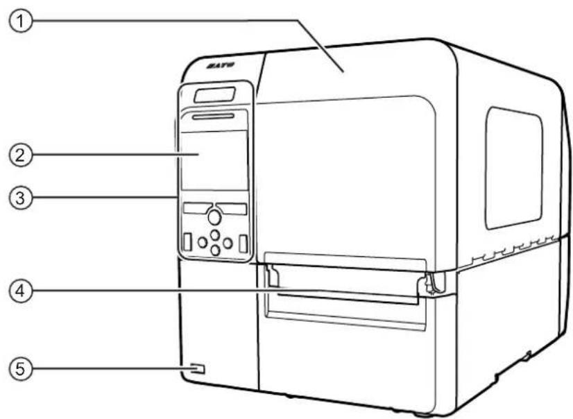
① Top cover
② Color LCD
③ Operator panel
④ Media discharge outlet
⑤ USB connector (Type A) Enable the storage of printer setting information with USB memory and for connecting other devices like a barcode verifier, barcode scanner or a keyboard.
CAUTION
Be sure to perform a virus check for the USB memory before connecting it to the printer. SATO Corporation shall not be held responsible for a malfunction of the printer caused by a virus infection through the USB memory.
Note
The pictures in this manual show the CL4NX unless otherwise stated.
1.1.2 Rear View
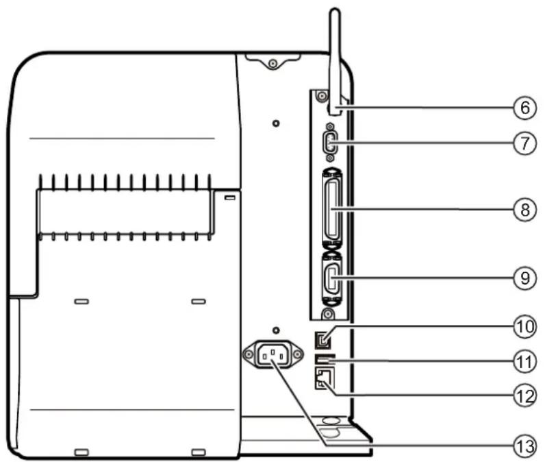
⑥ Wireless LAN antenna (optional)
Connector for installation of optional wireless LAN antenna.
⑦ RS-232C connector
To connect the printer to the computer using the RS-232C serial interface.
⑧ IEEE1284 connector
To connect the printer to the computer using the IEEE1284 interface.
⑨ EXT connector (External signal interface)
Interface connector for external signals. Connect an optional device to this terminal.
⑩ USB connector (Type B)
To connect the printer to the computer using the USB interface.
⑪ USB connector (Type A)
Enable the storage of printer setting information with USB memory and for connecting other devices like a barcode verifier, barcode scanner or a keyboard.
CAUTION
Be sure to perform a virus check for the USB memory before connecting it to the printer. SATO Corporation shall not be held responsible for a malfunction of the printer caused by a virus infection through the USB memory.
⑫ LAN connector
To connect printer to the network using the LAN interface.
⑬ AC input terminal
Supplies power to the printer through the inserted power cord.
Before connecting, make sure that the AC voltage of your region is in the range of AC 100 to 240 V, 50 to 60 Hz.
1.1.3 Internal View
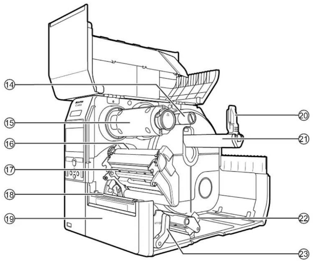
⑭ Ribbon supply spindle
⑮ Ribbon rewind spindle
⑯ Ribbon roller
⑰ Print head (Consumables)
Creates an image directly on the media or by using a ribbon. Highest print quality is achieved when regular maintenance is performed.
⑱ Platen roller (Consumables)
⑲ Front cover
⑳ Media holder guide
Used to hold the media roll.
②1 Media roll holder
Hang the media roll to the bar.
⑳ Media guide
②3 Head lock lever
Used to release the print head assembly.
1.2 Parts on the Operator Panel
1.2.1 Operator Panel
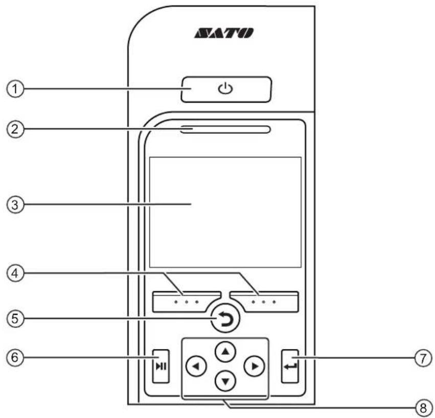
① ⏻ Power button
Press the power button for more than one second to power on the printer.
Press the power button for more than two seconds to power off the printer.
② LED indicator
③ Color LCD
④ Soft buttons
The functions change depending on the screen. The functions of the buttons are indicated on the bottom of the screen.
(For example, when in offline mode, left soft button: ONLINE; right soft button: FEED)
⑤ Back button
Returns to the previous screen.
⑥ ▶ Line button
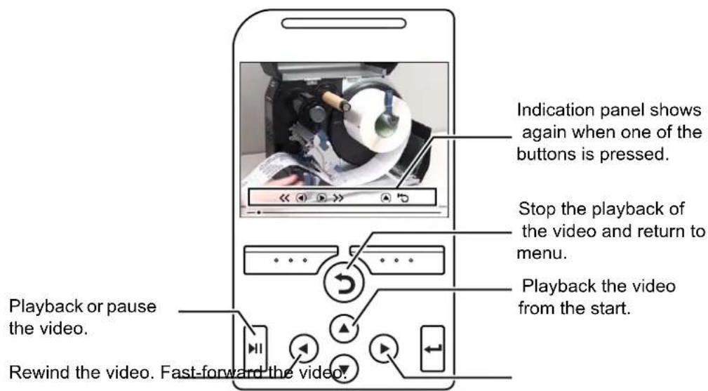
Toggle between online/offline mode or playback/pause the video.
⑦ ← Enter button
Confirm the selected item or setting value.
⑧ ◀/▶/ Arrow buttons
Navigate the selection in the screen menu.
1.2.2 LED Indicator
| LED Indicator Color | Description | |
 | Blue Online | mode |
 | (Light off) | Power off or offline mode |
 | Red Printer | error (For example, when the ribbon runs out) |
 Flashes at intervals of two seconds. Flashes at intervals of two seconds. | Blue Sleep | mode (energy saving mode) |
Note
If the printer enters sleep mode during a printer error status (LED lights red), the LED indicator will flash blue at intervals of two seconds.
This page is intentionally left blank.
2
Installing the Printer
2.1 Installation Precautions
Install this printer in a location as follows:
- A location that is horizontal and stable.
- A location that has sufficient space for operating the printer.
Do not install this printer in a location as follows. Doing so could cause the printer to malfunction.
- A location that is subject to vibration.
- A location with high temperature and humidity.
- A dusty location.
- A location exposed to direct sunlight.
- A location with a lot of electrical noise.
- A location with a large fluctuation in power.
- A location with an explosive atmosphere (flammable gas or vapor).
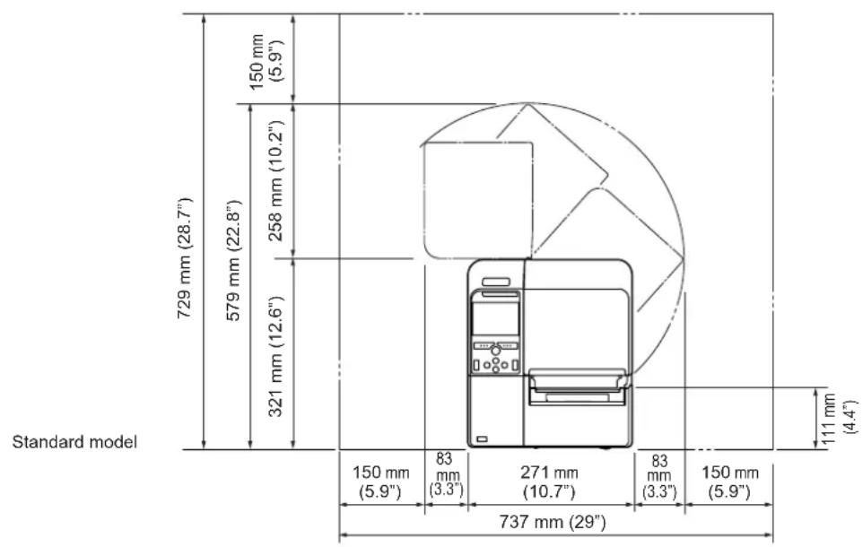
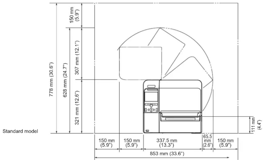
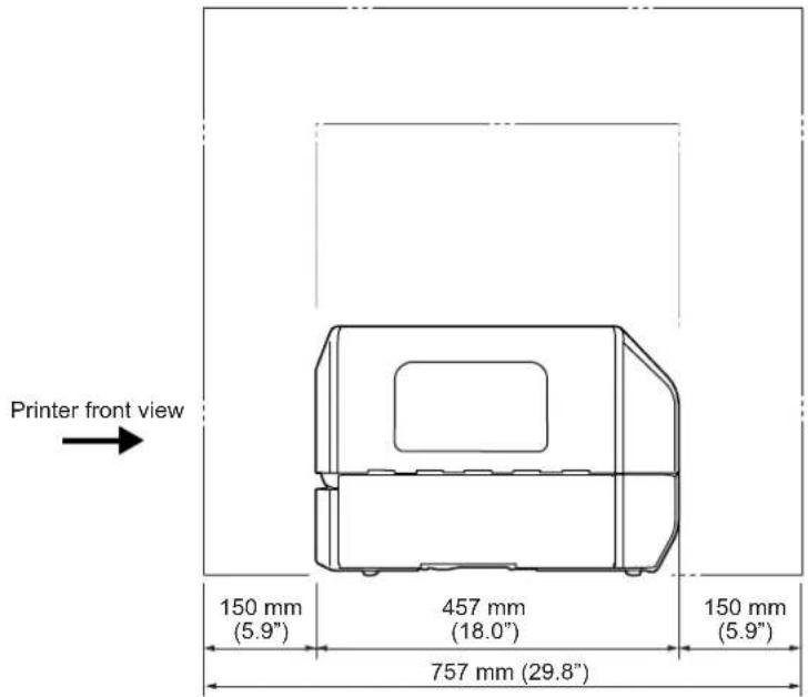
2.2 Installation Space
Make sure that there is sufficient space around the printer so that the top cover can be fully opened when operating or cleaning the printer, or replacing consumables.
2.2.1 Front View (CL4NX)
2.2.2 Front View (CL6NX)
2.2.3 Side View (CL4NX/CL6NX)
Make sure that there is sufficient space on the rear side of the printer so that no stress is applied to the power cord or cables connected to the printer.
2.2.4 Bottom View (CL4NX)
2.2.5 Bottom View (CL6NX)
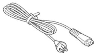
2.3 Checking the Bundled Accessories
After unpacking the printer, make sure that you have all the bundled accessories: if there are any missing items, contact the SATO reseller where you purchased the printer.
User documents
(Quick guide, Warranty, etc.)
AC power cord*
natural_image
Line drawing of a cable with two connectors and a power outlet (no text or symbols)* The shape of power plug varies depending on the region in which it was purchased.
Note
Keep the packaging box and cushioning material after installing the printer. You can pack the printer with this packaging box for shipment when requesting for repairs.
2.4 Connecting the Interface Cable
The connection of the interface cable is explained as follows:
2.4.1 Available Interfaces
This printer supports the following interfaces.
A printer connected with multiple interface cables can continue to operate when receiving data.
However, you cannot receive data from more than one interface at a time. Normally, do not use multiple interfaces at a time.
The printer prints the received data in the reception order. The next received data is stored in the receive buffer while the first data is printed.
• U S B
• LAN
- Bluetooth
• RS-232C
- IEEE1284
- External signal (EXT)
- Wireless LAN
natural_image
Technical line drawing of a device rear panel with connectors and ports (no text or symbols)Note
The wireless LAN interface is optional.

CAUTION
Do not connect or disconnect the interface cables (or use a switch box) with power supplied to either the printer or computer. This may cause damage to the interface circuitry in the printer or computer and is not covered by warranty.
2.4.2 Interface Settings
You can set the various interface settings of the printer through Interface in the Settings menu. For details, refer to Interface in chapter 4 Operation and Configuration.
2.5 Connecting the Power Cord

WARNING
- Do not touch the power button, connect or disconnect the power cord while your hands are wet. Doing so could cause an electric shock.
• Always connect the ground wire to a ground terminal. Electric shock could occur if you do not.

CAUTION
- The attached power cord is designed exclusively for this printer.
- Do not use the attached power cord with other devices.
1
Connect the power cord to the AC input terminal ① at the rear of the printer.
Take note of the orientation of the connector. Secure the printer with one hand, and insert the connector tightly.
2
Insert the power plug into an AC outlet.
Make sure that the AC voltage of your region is in the range of AC 100 - 240 V, 50 - 60 Hz. If your local voltage is not in the stated range, contact your SATO reseller or technical support center.
*The shape of the power plug varies depending on the region in which it was purchased.
natural_image
Diagram showing a plug inserted into an electrical outlet with an arrow indicating the insertion point (no text or symbols present)Note
This product is also designed for IT power distribution system with phase-to-phase voltage 230 V.
2.6 Power On/Off the Printer

WARNING
Do not touch the power button, connect or disconnect the power cord while your hands are wet. Doing so could cause an electric shock.

CAUTION
An incorrect power on/off operation may damage the printer settings. In such a case, the printer settings are reset to their default values.
Note
You can power on/off the printer from the main power source by enabling Start on AC under the System menu.
2.6.1 Power On the Printer
1 Press the ⏻ power button on the operator panel for more than one second to power on the printer.
2 Online shows on the screen and the LED lights blue.
2.6.2 Power Off the Printer

CAUTION
- Do not power off the printer during operation, such as when printing or updating. Doing so could cause a malfunction of the printer.
- Do not disconnect the power cord until the powering off process is completed on the printer.
1
Make sure that the printer is in offline mode before you power off.
If Online shows on the screen, press the ▶ button to change to offline mode.
1
Press the ⏻ power button for more than two seconds to power off the printer.

2.7 Starting Up the Printer (Startup Guide)
When you power on the printer for the first time after purchase, the display shows the startup guide. The startup guide is a function to help you through the initial printer configuration, such as setting date and time, and loading the ribbon and media.
You can cancel the startup guide and perform the configuration later from the menu.
*If you have installed the optional RTC (Real Time Clock) kit, the time zone, date and time setting screens show.
2.7.1 Startup Screen
The startup screen shows when you first power on the printer.

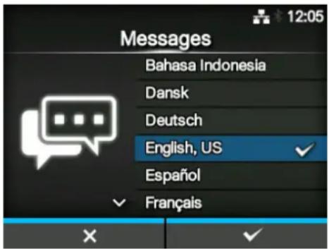
2.7.2 Language Selection
Select the display language.
Select the language name using the ▲▼ buttons, then press the right soft button or ← button to confirm.
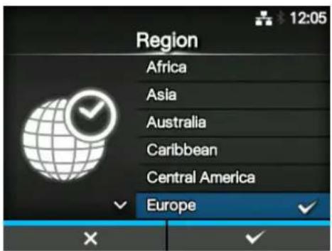
2.7.3 Region Setting with Optional RTC
Set the region (time zone).
Select the region using the ▲buttons, then press the right soft button or ◀button to confirm.
2.7.4 City Setting with Optional RTC
Set the city (time zone).
Select the city using the ▲buttons, then press the right soft button or ◀button to confirm.
2.7.5 Date Setting with Optional RTC
Set the date.
Select the current value using the ▲ buttons, and move the cursor using the ▼ buttons. When you have completed the date setting, press the right soft button or ◀ button to confirm.
2.7.6 Time Setting with Optional RTC
Set the time.
Select the current value using the ▲ buttons, and move the cursor using the ▲ buttons.
When you have completed the time setting, press the right soft button or <button to confirm.
Note
The time is set in 24-hour format.
2.7.7 Print Method Setting
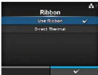
Set whether to use the ribbon or direct thermal media to print.
The options are as follows:
- Use Ribbon: Print with a ribbon.
- Direct Thermal: Print using direct thermal media.
Select the print method using the ▲ buttons, then press the right soft button or ◀ button to confirm.
2.7.8 Ribbon Setting
Load the ribbon.
*Shows if you have selected Use Ribbon in the print method setting.
You can check the setting method of the ribbon through the video. Press the ◀ button to watch the video.
Press the Button to stop the video and return to the previous screen.
After you complete the ribbon setting, press the right soft button to go to the next screen.
natural_image
Close-up of a hand pressing down on a black cylindrical mechanical component (no visible text or symbols)2.7.9 Setting the Media Sensor Type
Set the type of sensor for sensing the media. The available options will vary depending on the default print mode of your printer.
The options are as follows:
- None: Disable the media sensor.
- Gap: Use the transmissive type sensor.
• I-Mark: Use the reflective type sensor.
Select the media sensor type using the ▲▼ buttons, then press the right soft button or ← button to confirm.
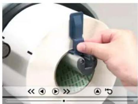
2.7.10 Media Setting
Load the media.
You can check the setting method of the media through the video.
Press the ◀ button to select video mode.
Note (for CL4NX only)
When you are using the linerless model, the video is shown immediately after the ◀ button is pressed.
The selection screen of the video for playback shows. (Not available for linerless model of CL4NX.)
Select the video to playback using the ▲▼ buttons, then press the right soft button or ← button to playback the video.
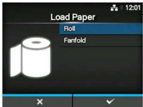
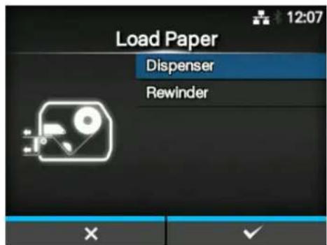
The options are as follows:
The options vary depending on the printer model.
Standard Model and Cutter Model
- Roll: Shows the video on how to load the media roll.
- Fanfold: Shows the video on how to load the fan-fold media.
Dispenser Model
- Dispenser: Shows the video on how to eject the liner out of the printer.
- Rewinder: Shows the video on how to rewind the liner in the printer.
Press the Button to stop the video and return to the previous screen.
After you complete the media setting, press the right soft button to go to the next screen.
natural_image
Close-up of a hand adjusting a white electronic device with a blue clip, showing green internal structure (no text or symbols visible)2.7.11 Confirmation Screen
This screen shows when the startup guide completes.
If you want the startup guide to show the next time you start up, press the left soft button. If not, press the right soft button.
When you press one of the soft buttons, the printer automatically feeds the media (to the print head position) and enters online mode.
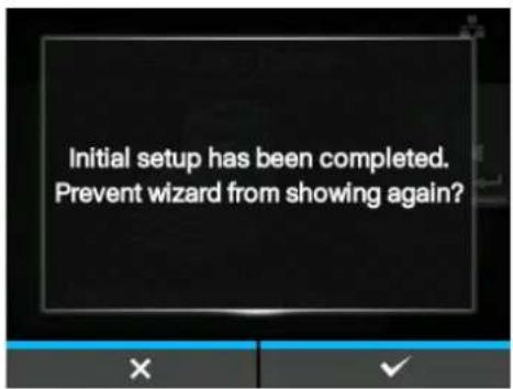
Note
You can enable or disable the startup guide in Startup Guide under the Tools menu.
2.7.12 Startup Guide Cancelation
You can cancel the startup guide at any time. When you press the left soft button on the setting screen, the screen to the right shows.
Select whether or not to show the startup guide during the next startup using the ▲ buttons, and press the right soft button to confirm.
To cancel and return to the startup guide setting, press the left soft button.
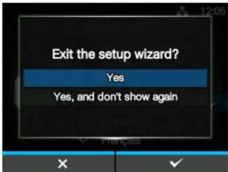
Note
- You can enable or disable the startup guide in Startup Guide under the Tools menu.
• Even if you cancel the startup guide during play, the printer will save the settings you have changed.
This page is intentionally left blank.
3
Loading the Ribbon and Media
This printer supports two types of print methods, thermal transfer and direct thermal. Thermal transfer printing transfers the ink of the ribbon to the media. Direct thermal printing creates the image on direct thermal media. Ribbon is not necessary if you are using direct thermal media.
3.1 Checking the Ink Side of the Ribbon
There are two wind directions for the ribbon. Face-out means the ink is on the outer side and Face-in means the ink is on the inner side. This printer supports both wind directions. You can examine the ink side of the ribbon using the following procedure:
1 Place the outer side of the ribbon onto the media (touching).
2 Scratch the inner side of the ribbon with your fingernail or a pointed object.
3 If there is a mark on the media, the ink is coated on the outer side of the ribbon.
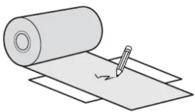
natural_image
Illustration of a rolled paper sheet with a pencil and eraser, no text or symbols present
The ink is coated on the inner side. (Face-in ribbon)
The ink is coated on the outer side. (Face-out ribbon)
3.2 Loading the Ribbon
Use genuine SATO media and ribbons for the printer, for optimum print quality.

CAUTION
• The print head and its surroundings are hot after printing. Be careful not to touch it, to avoid being burned.
- Touching the edge of the print head with your bare hand could cause injury.
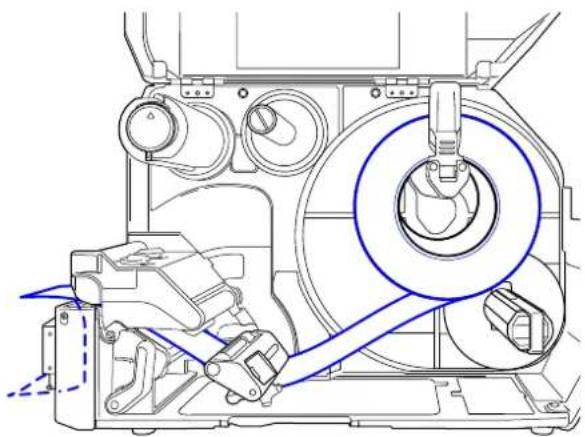
The routing path of the ribbon is shown in the right picture.

Face-in ribbon
Face-out ribbon
natural_image
Technical line drawing of a mechanical assembly with no visible text or symbolsNote
You can also refer to the sticker located on the inner side of the top cover.
1
Open the top cover ①.

CAUTION
Open the top cover fully to prevent accidental drop of the cover.
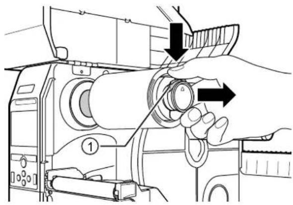
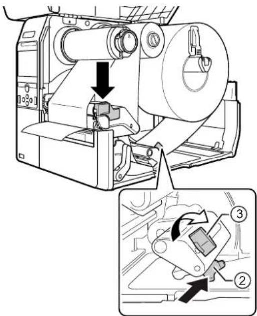
2 Push the ribbon rewind spindle ② all the way in.
If there is any ribbon on the ribbon rewind spindle, remove it.
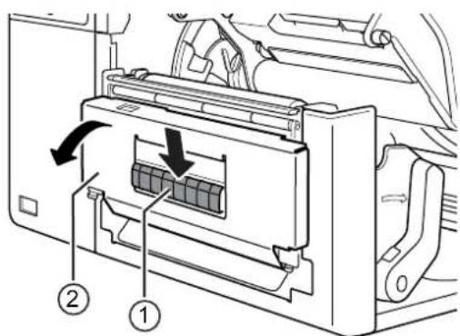
3 Push the head lock lever ③ towards the rear.
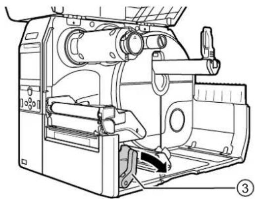
natural_image
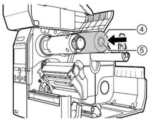
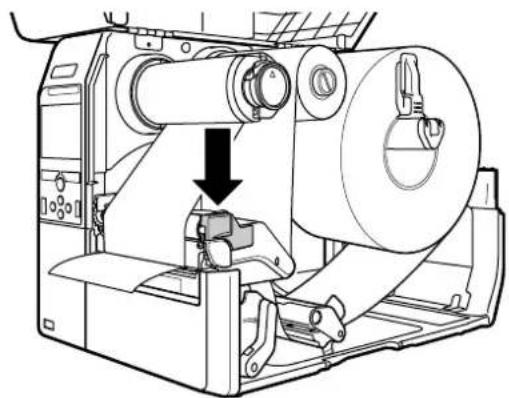
Technical line drawing of a mechanical device with internal components and mounting base (no text or symbols)4 Load the ribbon ④ onto the ribbon supply spindle ⑤.
While taking note of the wind direction, insert the ribbon all the way in.
5 From the ribbon supply spindle ⑤, pass the ribbon below the print head ⑥.
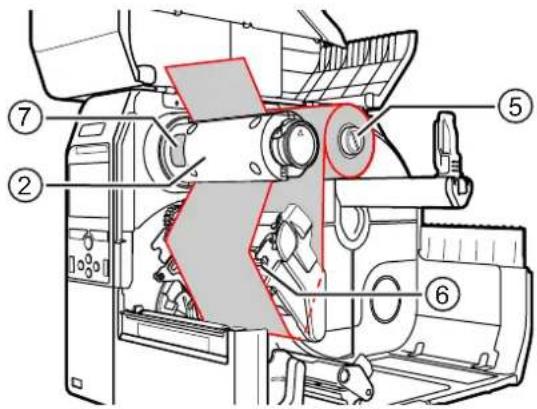
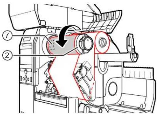
6 Wind the ribbon counterclockwise to the ribbon rewind spindle ② and grip sheet ⑦.
Turn the ribbon rewind spindle counterclockwise for several rounds, to wind the ribbon.
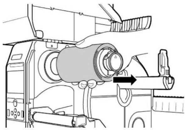
7 If the media is already loaded, press the print head down until the head lock lever is locked.
If the media is not loaded, continue with Section 3.5 Loading Media.
natural_image
Technical line drawing of a mechanical device with a cylindrical component and a downward arrow indicating motion (no text or symbols)8 Close the top cover.
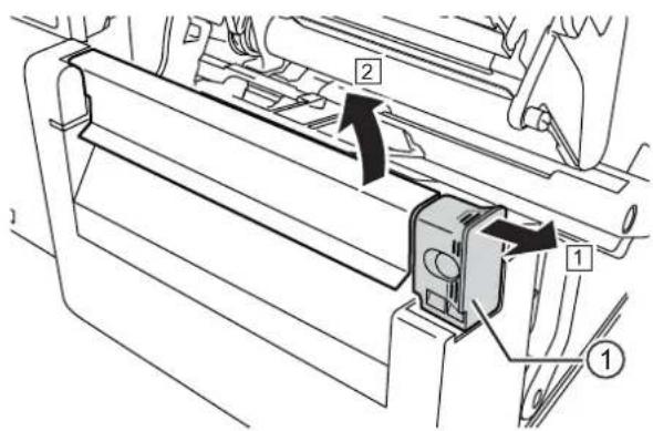
3.3 Removing the Ribbon
1 Press the tab ① on the tip of the ribbon rewind spindle to pull it out.
natural_image
Line drawing of a sewing machine with hands adjusting the button (no text or symbols)2 Pull to remove the used ribbon from the ribbon rewind spindle.
3 Push the ribbon rewind spindle all the way in.
natural_image
Technical line drawing of a sewing machine with a hand operating the component (no text or symbols present)3.4 Usable Media
This printer can print on two types of media; media roll and fan-fold media. The printer uses media sensors to detect I-marks or Gaps on the media in order to precisely print the content.
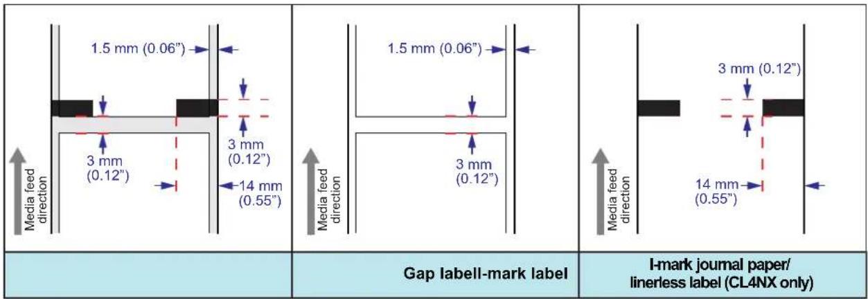
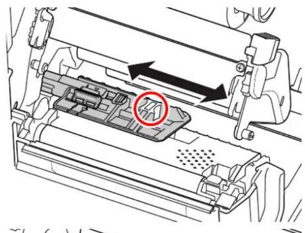
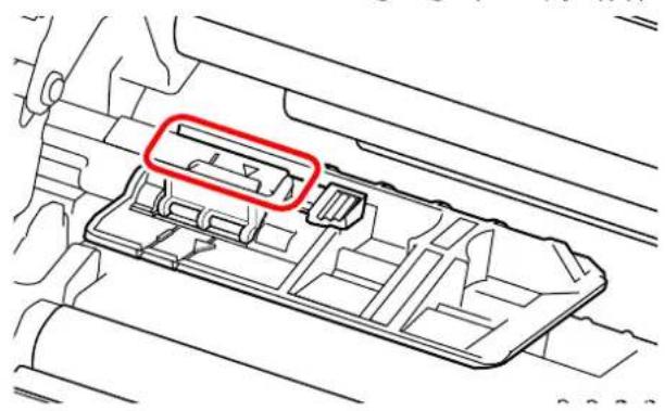
3.4.1 Adjusting the Position of the Media Sensor
When you use nonstandard media (for example, media with printing on the underside, or media with a special shape), the media sensor cannot sense the I-mark or Gap of the media correctly. In such a case, adjust the position of the media sensor to sense the I-mark or Gap correctly.
Adjust the media sensor guide to the position where it can sense the I-mark or Gap of the media.
natural_image
Mechanical assembly diagram showing internal components with arrows indicating movement (no text or symbols)The I-mark sensor is below the mark, and the Gap sensor is below the mark.
natural_image
Technical line drawing of a mechanical component with a red annotation highlighting a specific area (no text or symbols present)3.5 Loading Media
Use genuine media and ribbons for the printer, for optimum print quality.

CAUTION
• The print head and its surroundings are hot after printing. Be careful not to touch it, to avoid being burned.
- Touching the edge of the print head with your bare hand could cause injury.
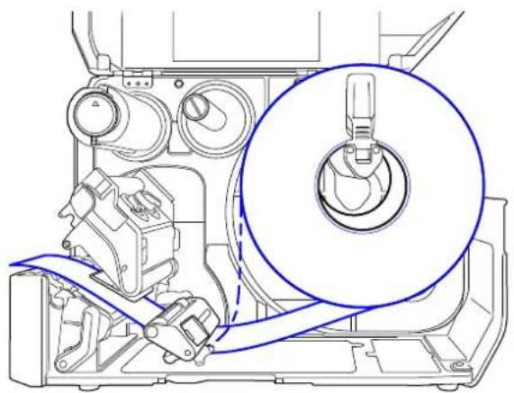
3.5.1 Loading Media Roll
The routing path of the media is shown in the right picture.
When loading the media, make sure that the print side is facing up.

natural_image
Technical line drawing of a mechanical assembly with a magnified circular detail (no text or symbols)1 Open the top cover.

CAUTION
Open the top cover fully to prevent accidental drop of the cover.
2 Push the head lock lever towards the rear to unlock the print head.
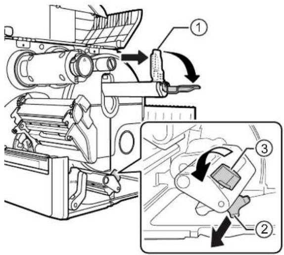
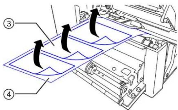
3 Pull the media holder guide ① and media guide ② away from the printer.
Turn the knob ③ counterclockwise to release the media guide.
4 Load the media in the media holder ④. Make sure that the media roll is all the way in to inside of the printer.
5 Push the media holder guide ① lightly against the media roll.
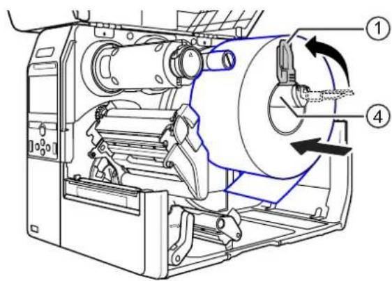
6 Pass the media below the media damper ⑤ and media sensor guide ⑥ while pushing the media to inside of the printer.
Make sure that the end of the media extends out the front of the printer.
7 Press the print head down until the head lock lever is locked.
8 Press the media guide ② lightly against the end of the media, then turn the knob ③ to lock the media guide.
9 Close the top cover.
10 After loading the media and ribbon, perform a test print to make sure that the media is loaded correctly.
Refer to the Test Print menu in Section 4.4.5 Tools Menu for details on how to perform a test print.

CAUTION
When closing the top cover, be careful not to pinch your fingers.
3.5.2 Loading Fan-fold Media
Place the fan-fold media on a flat location, then load the media from the rear of the printer or from the media slot on the bottom of the printer.
The routing path of the media is shown in the right picture.
When loading the media, make sure that the print side faces up.
After passing the media through the slot, refer to steps 5 through 10 of Section
3.5.1 Loading Media Roll to load the media.

Load the media from the rear of the printer.

Load the media from the bottom of the printer.
natural_image
Technical line drawing of a mechanical assembly with internal components and a 3D block base (no text or symbols)Note
If a media jam frequently occurs with the media being loaded from the bottom of the printer, change the load location to the rear of the printer.
3.5.3 Loading Media with the Optional Cutter
Refer to the procedure in Section 3.5.1 Loading Media Roll or Section 3.5.2 Loading Fan-fold Media to load the media.
For models with a cutter installed, pull the tab ① of the cutter unit in the direction shown, then open up the cutter-open lever before passing the media through it.
After loading media, close the cutter-open lever and then push the tab ① in the reverse direction to lock it.

CAUTION
Be careful not to touch the cutter blade.
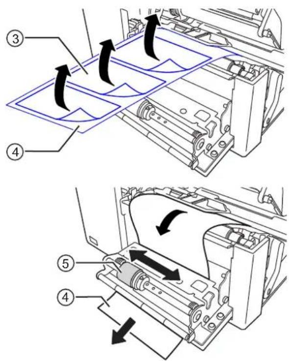
3.5.4 Loading Media with an Optional Dispenser and Liner Discharge Outlet
This section describes the procedure to dispense the label and eject the liner out of the printer.
1 Refer to steps 1 through 6 of Section 3.5.1 Loading Media Roll to load the media.
natural_image
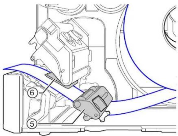
Technical line drawing of a mechanical assembly with no visible text or symbols2 Press the tab ① at the front of the printer to open the dispenser unit ②.

3 Remove about 30 cm (11.8") of labels ③ from the liner ④, then pass the liner ④ through the gap of the dispenser unit to the outside of the printer.
4 Adjust the dispenser roller ⑤ to the center of the label.
5 Close the dispenser unit.
6 Close the print head and top cover.
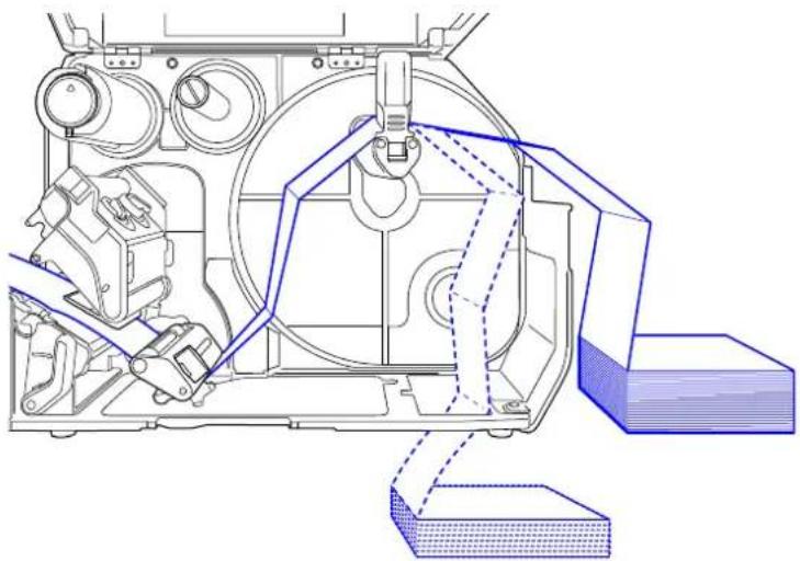
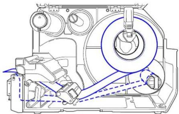
3.5.5 Loading Media with an Optional Dispenser and Liner Rewinder
This section describes the procedure to dispense the label and rewind the liner in the printer.
Note
The maximum diameter of the liner that can be rewound in the printer is 120 mm (4.72").
The routing path of the media is shown in the right picture.

natural_image
Technical line drawing of a mechanical assembly with no visible text or symbols1 Refer to steps 1 through 7 of Section 3.5.1 Loading Media Roll to load the media.
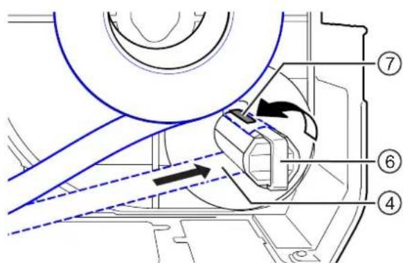
2 Press the tab ① at the front of the printer to open the dispenser unit ②.
3 Remove about 80 cm (31.5") of labels ③ from the liner ④, then pass the liner ④ through the gap of the dispenser unit to the inside of the printer.
4 Adjust the dispenser roller ⑤ to the center of the label.
5 Pass the liner ④ below the liner rewinder ⑥, then attach it with the clip ⑦.
6 Rotate the liner rewinder ⑥ counterclockwise by hand, to wind the liner.
7 Close the dispenser unit.
8 Close the print head and top cover.

3.5.6 Removing the Liner from the Rewinder
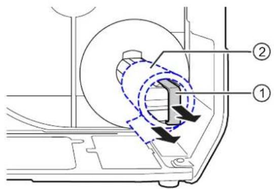
1 Pull the clip ① away from the printer then pull to remove the liner ②.
2 Place the clip back to its original position.
This page is intentionally left blank.

Operation and Configuration
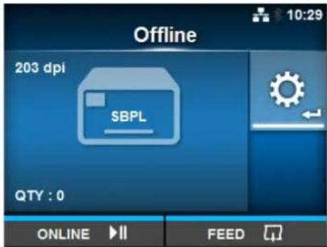
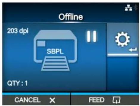
The display of the printer varies depending on the following modes:
• Online mode: refer to Section 4.1.1 Online Mode/Offline Mode.
- Offline mode: refer to Section 4.1.1 Online Mode/Offline Mode.
- Error display: refer to Section 4.1.3 Error Icon.
- Settings mode: refer to Section 4.2 Settings Mode.
4.1 Display and Operation
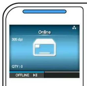
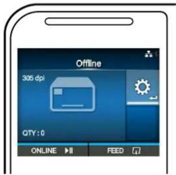
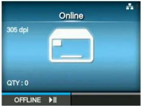
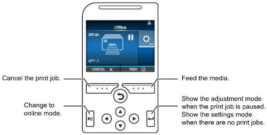
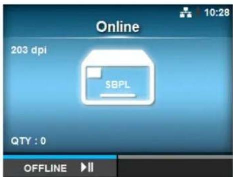
4.1.1 Online Mode/Offline Mode
In online mode, you can execute the print job.
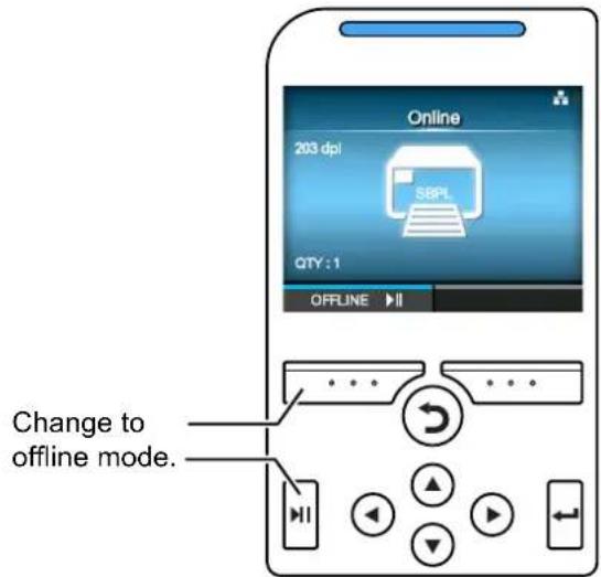
In offline mode, the print job will stop.
You can adjust the print settings, cancel the print job or feed the media.
After you complete or cancel the print job, you can show the settings mode.
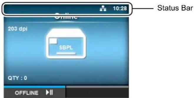
4.1.2 Status Icon
The icons on the status bar of the display show the printer status.
- Communication Interface Status
| Icon Description | |
 | Bluetooth is enabled but not connected. |
 | Bluetooth is enabled and connected. |
 | Network link is enabled but not connected. |
 | Network link is enabled and connected. |
 | Not connected to the NTP time server. |
 | Wi-Fi is not connected. |
 | Wi-Fi is connected.Signal Level: 1 |
 | Wi-Fi is connected.Signal Level: 2 |
 | Wi-Fi is connected.Signal Level: 3 |
 | Wi-Fi is connected.Signal Level: 4 |
 | Wi-Fi Direct is not connected. |
 | Wi-Fi Direct is connected.Signal Level: 1 |
 | Wi-Fi Direct is connected.Signal Level: 2 |
 | Wi-Fi Direct is connected.Signal Level: 3 |
 | Wi-Fi Direct is connected or the printer is set to act as an access point.Signal Level: 4 |
 | Printer is connected to USB host. |
 | Waiting for external input/output signal. |
 | RFID mode is enabled (CL4NX only). |
 | Standard code is disabled (Non-standard code). |
- USB Memory Status
| Icon Description | |
 | USB memory is connected. |
- Barcode Verifier Status
| Icon Description | |
 | Barcode verifier is connected. |
- Print Job Status
| Icon Description | |
 | Waiting for media removal. Remove the media. |
 | Ribbon is near the end. Prepare a new ribbon. |
 | Command error detected. Check the print data. |
 | Receive buffer is nearly full. Wait until the printer starts printing the previously sent data, and then send the next data. |
 | Defective print head is detected. Replace the print head. |
 | Incompatible print head is detected. Replace the print head. |
- Maintenance Status
| Icon Description | |
 | Clean the print head or platen roller. |
 | Replace the print head. |
 | Replace the platen roller. |
 | Replace the cutter unit. |
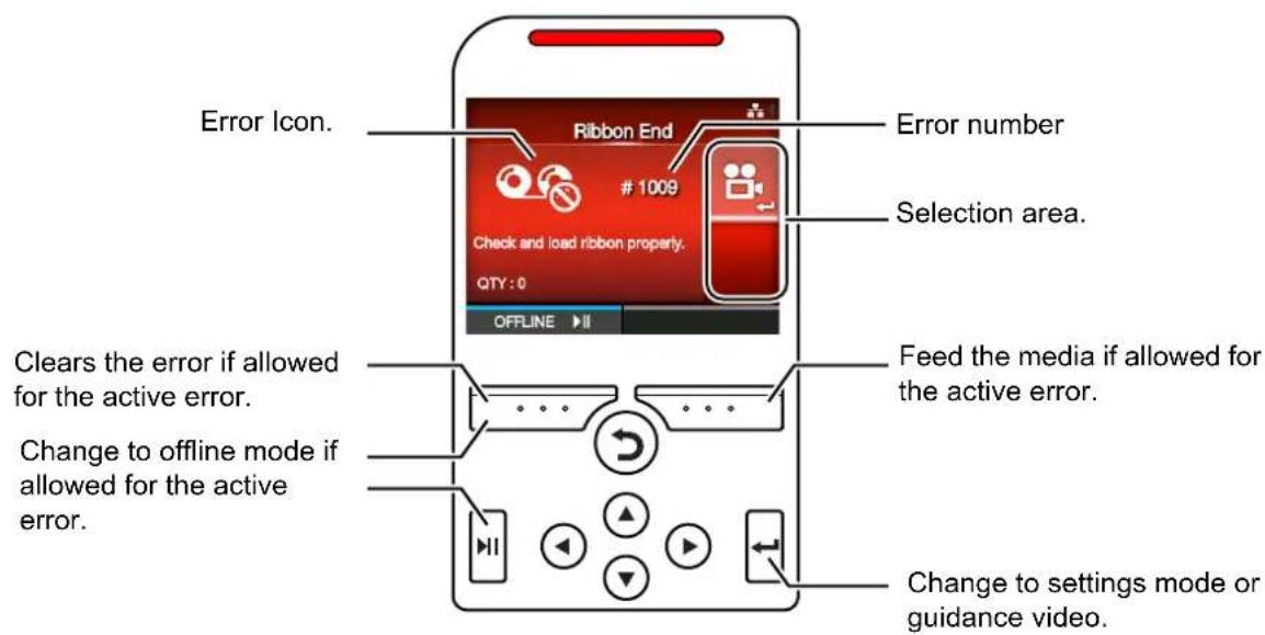
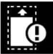
4.1.3 Error Icon
When a printer error occurs, the error status shows on the screen with an icon.
When an error occurs, you can perform the following operations:
- Change to offline mode.
- Cancel the error.
- Feed the media.
- Change to settings mode.
- Change to guidance video.
Note
The available operations vary, depending on the situation.
- Error Icon
| Icon Description | |
 | Paper end is detected. |
 | Ribbon end is detected. |
 | Print data is larger than the media size. |
 | Sensor error is detected. |
 | Print head is unlocked. |
 | Print head error is detected. |
 | • Communication error is detected. • BCC error is detected. • CRC error is detected. |
 | Receive buffer overflow. |
 | Cutter error is detected. |
 | • USB memory is not accessible. • There is no free space in the USB memory. |
 | Calendar error is detected. |
 | • Writing/reading information to/from the RFID tag failed (CL4NX only). • With Non-RFID warning enabled and RFID tag loaded, the items received do not contain an RFID issue command (CL4NX only). |
 | • Wireless LAN setting error is detected. • Authentication with the server failed. • Authentication with the server timed out. |
 | Printer error is detected. |
 | The temperature of the print head has exceeded the tolerance range. |
 | RFID module is defective (CL4NX only). |
 | Bluetooth module is defective. |
 | Paper jam is detected. (CL4NX only) |
 | The barcode verifier is not detected at printer startup when the barcode check mode is enabled. |
 | The barcode could not be read.The read result of the barcode does not match the command data. |
4.1.4 Guidance Video
The printer contains the following guidance videos for visual reference of printer operations.
| No. | Guidance Video | Show video from | ||
| Error screen | Startup Guide | Information menu | ||
| 1 Media roll loading (Standard) - Possible Possible | ||||
| 2 Media roll loading (Cutter) - Possible Possible | ||||
| 3 Media roll loading (Linerless) (CL4NX only) - Possible Possible | ||||
| 4 Media roll loading (Dispenser) - Possible Possible | ||||
| 5 Media roll loading (Dispenser with rewinder) - Possible Possible | ||||
| 6 Fan-fold media loading (Standard) - Possible Possible | ||||
| 7 Fan-fold media loading (Cutter) | - Possible Possible | |||
| 8 Ribbon loading | - Possible Possible | |||
| 9 Media roll replacement (Standard) | Possible - Possible | |||
| 10 Media roll replacement (Cutter) | Possible - Possible | |||
| 11 | Media roll replacement (Linerless) (CL4NX only) | Possible | - | Possible |
| 12 Media roll replacement (Dispenser) | Possible - Possible | |||
| 13 | Media roll replacement (Dispenser with rewinder) | Possible | - | Possible |
| 14 | Fan-fold media replacement (Standard) | Possible - Possible | ||
| 15 | Fan-fold media replacement (Cutter) | Possible - Possible | ||
| 16 Ribbon replacement | Possible - Possible | |||
| 17 Print head replacement | - | - Possible | ||
| 18 Platen roller replacement | - | - Possible | ||
| 19 | Cleaning | - | - Possible | |
You can play the guidance video using the following procedures:
• To play the guidance video from the error screen
1 On the error screen, press the button to play the guidance video.
If there are more videos to choose from, press the arrow buttons to select the guidance video, then press ← button.
The guidance video will playback.
2 Follow the procedures to resolve the error according to the guidance video.
• To get access to the guidance video in online mode
1 Press the ▶ button in online mode.
The printer enters offline mode.
2 Press the button. The printer enters settings mode.
3 Select Information using the ◀/▶ buttons.
4 Press the ▶ button.
The item list shows.
5 Select Help using the ▲/▼ buttons.
6 Press the ◀ button.
The list of guidance videos shows.
7 Select the video for playback using the
▲ /▼ buttons, then press the button.
The guidance video will playback.
The guidance video operating procedures are described below:
4.1.5 How to Adjust the Print Settings During Printing
Follow the procedure below to adjust the print position, print darkness and print speed during printing.
1 Press the ▶ button to pause print job and change the printer to offline mode.
2 Press the button. The Adjustments menu shows.
3 Select an item and adjust the setting. For details on how to adjust settings, refer to Section 4.2 Settings Mode.
4 Press the button to return to offline mode.
5 Press the ▶ button to change to online mode. The print job resumes with the adjusted settings.
Note
When Prioritize in the Printing > Advanced menu has been set to Commands and the print settings have been specified by command, the changes made in the Adjustments menu will be applied only to the data already analyzed at that time. The settings specified by command will be applied to the rest of the data.
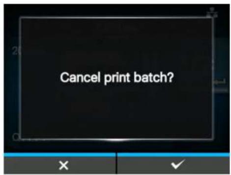
4.1.6 How to Cancel the Print Job
Cancel the print job according to the following procedure. When the print job is canceled, the data stored in the receive buffer of the printer is also deleted.
1 Press the button to change the printer to offline mode.
2 Press the left soft button.
A message shows, confirming that you want to cancel the print job.

3 Press the right soft button. The print job will be canceled.
4.2 Settings Mode
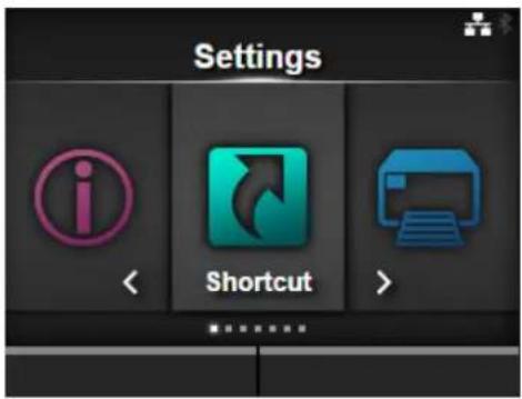
In settings mode, the following menus show:
| Menu Description | |
| Shortcut Directly access | frequently used settings. |
| Printing Access the settings related to printing. | |
| Interface Access the settings related to the interfaces. | |
| Applications Access the settings related to the printer's command language. | |
| System Access the settings related to the display language, buzzer volume etc. | |
| Tools Access the test print, initialization and other settings. | |
| Information Access the printer information and help videos. | |
4.2.1 Changing to Settings Mode
The settings mode can be shown when no print jobs remain in the printer. Change the printer to settings mode according to the following procedure:
1 Press the ▶ button in online mode. The printer enters offline mode.
2 Press the button.
The printer enters settings mode.
To exit the settings mode, press the ▶|| button.
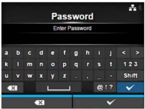
4.2.2 Log In to/Log Out of the Settings Mode
After entering the settings mode, you will be prompted with password if password is enabled (Refer to Password Enable in System > Password).
When you exit from the settings mode after a successful login, LOG OUT shows on the bottom left of the screen.
Press the left soft button if you want to log out immediately.
Password is required to enter the settings mode again.
Note
With password enabled, if no button is pressed for about ten minutes after login, the login session will end automatically. Password is required to enter the settings mode again.
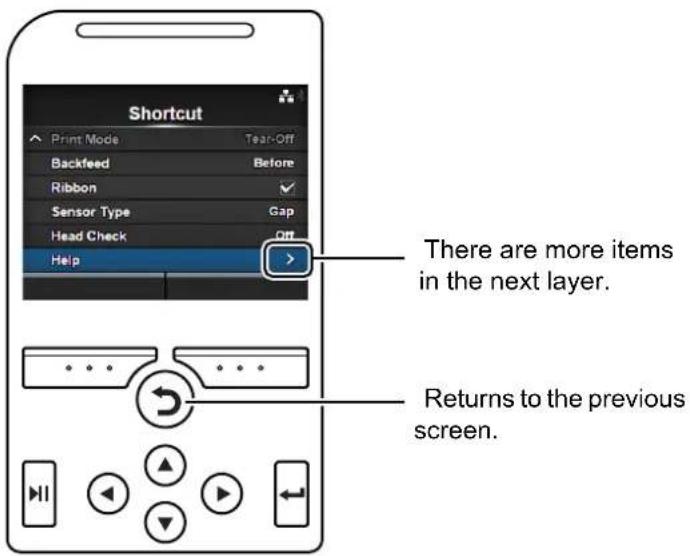
4.2.3 Item Selection
Select an item in settings mode according to the following procedure:
1 Select menu using the 🔊 buttons.
2 Press the button.
The item list shows.

3 Select an item using the ▲buttons.
4 Press the button.
If the selected item is a setting item, the setting screen shows.
If the selected item is a command, the command will be executed.
Items with a “>” indicated on the right side have more items in the next layer of the submenu.
Press the ▶ or button to show the next layer.
Similarly, select an item using the ▲/▼ and buttons.
Press the Button to return to the previous screen.
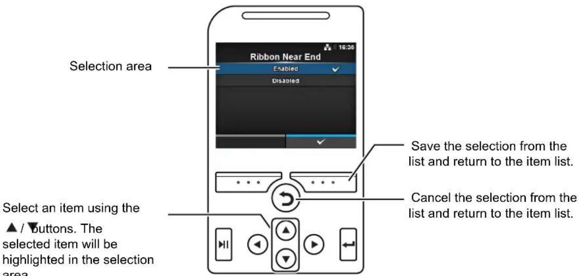
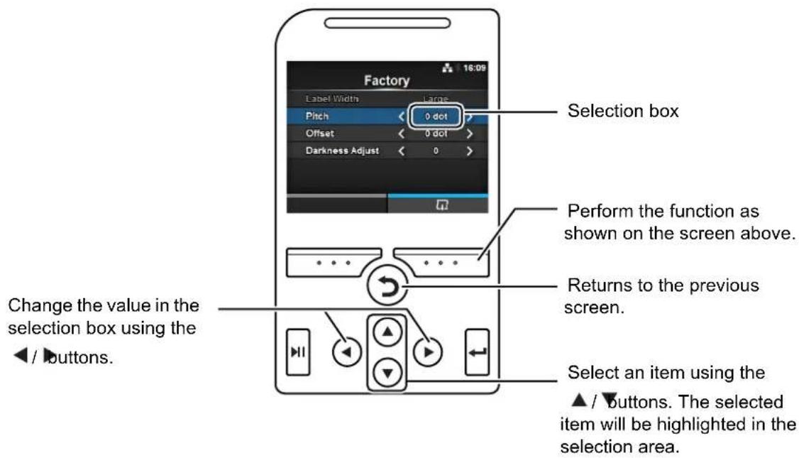
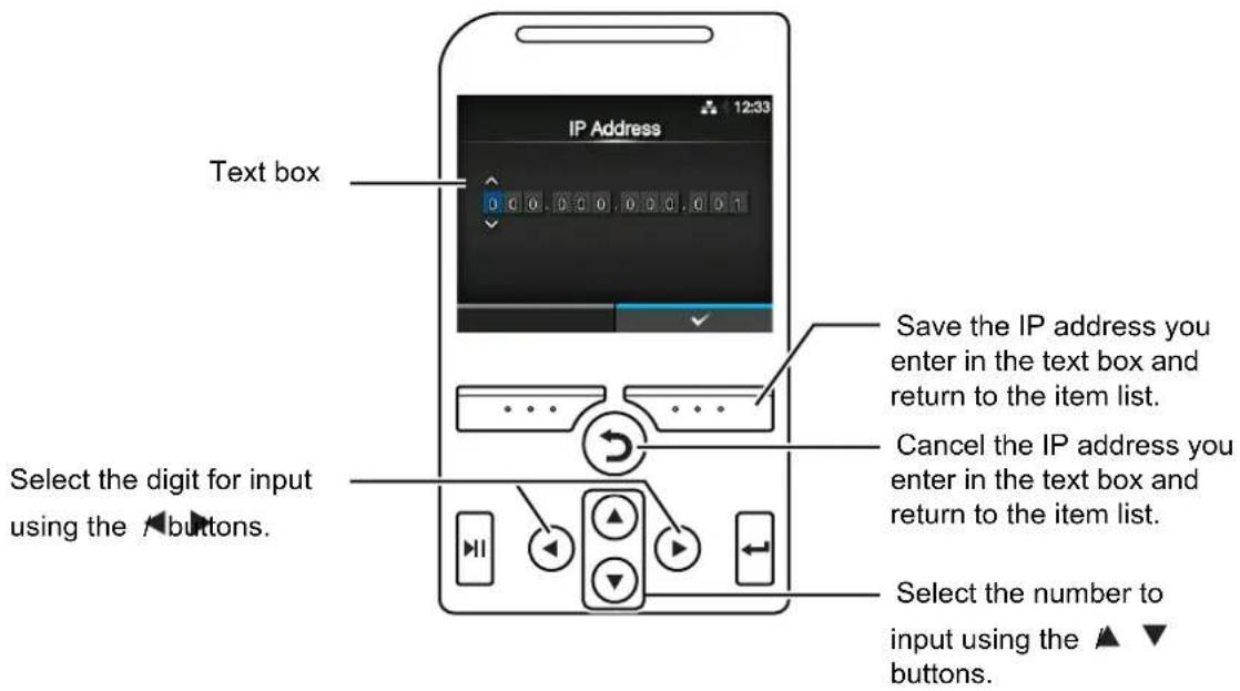
4.2.4 Setting Value Input or Selection
This section describes the alphanumeric input on the setting screen and how to select an item from the list.
Note
You can also input alphanumeric characters from a USB keyboard by connecting it to the printer.
- Character Input
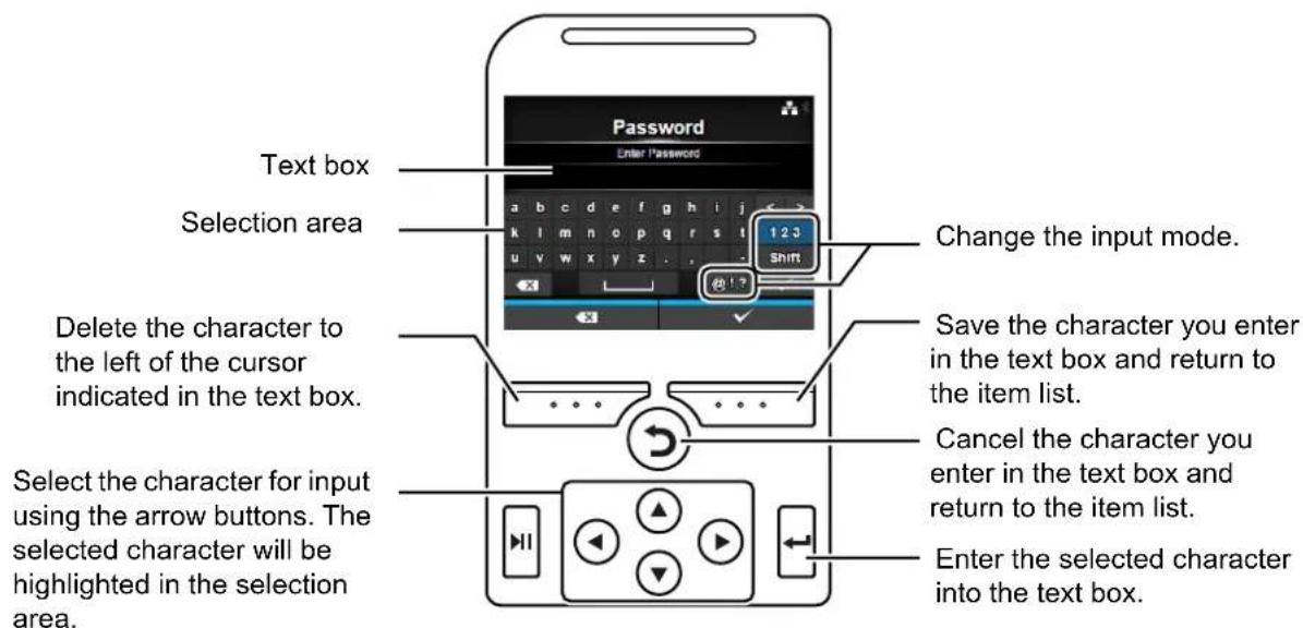
- Numeric Input
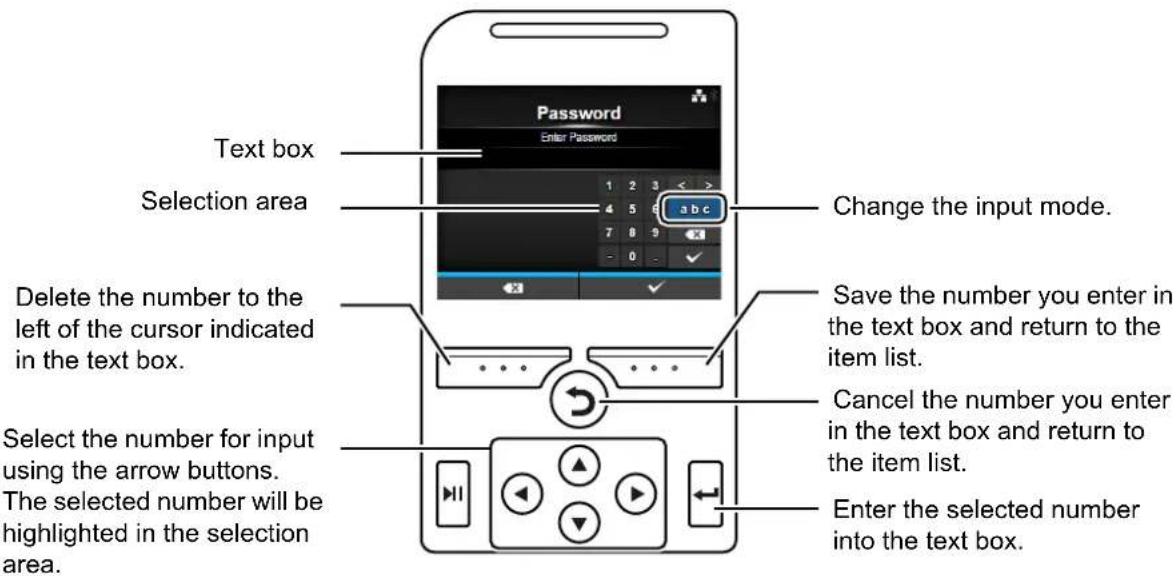
- Selection from the list
- Selection from the box
- Entering an IP address
4.3 Settings Menu Tree Structure
There are six main menus in Settings mode and each menu contains many layers of submenus. Frequently used settings are also listed in the Shortcut menu so that you can directly access them. The tables below outline the Settings menus tree structure. Refer to the tree structure to understand where information is located in the setting menus. Click on the items in blue to link directly to the details of the selected items.
 | Shortcut | Shortcuts to frequently used settings | |
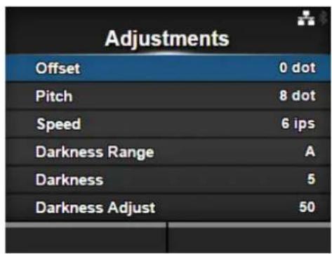
| Adjustments | |||
| Speed | |||
| Darkness Range | |||
| Darkness | |||
| Auto-mode | |||
| Print Mode | |||
| Backfeed | |||
| Ribbon | |||
| Sensor Type | |||
| Head Check | |||
| Help | |||

Printing Submenus
| Label Length | ||
| Label Width | ||
| Auto Measure | ||
| Ribbon | ||
| Ribbon Near End | ||
| Speed | ||
| Sensor Type | ||
| Auto-mode | ||
| Print Mode | ||
| Backfeed | ||
| Eject Cut | ||
| Darkness Range | ||
| Darkness | ||
| Imaging Vertical | ||
| Horizontal | ||
| Advanced Calibrate | Auto-calibration | |
| GAP Levels | ||
| GAP Slice Level | ||
| I-Mark Levels | ||
| I-Mark Slice Level | ||
| Head Check | ||
| Head Check Mode | ||
| Every Page | ||
| Check Media Size | ||
| Adjustments Offset | ||
| Pitch | ||
| Darkness Adjust | ||
| Start Online | ||
| Feed After Error | ||
| Feed At Power On | ||
| Finisher Feed | ||
| Paper End | ||
| Head Base Position | ||
| Prioritize | ||
| Reprint | ||
| Print End Position | ||
| Label Near End | ||

Interface Submenus
| Network Settings LAN IPv4 Mode | |||||
| DHCP/Renew Lease | |||||
| IP Address | |||||
| Netmask | |||||
| Gateway | |||||
| DNS | |||||
| IPv6 Mode | |||||
| DHCP/Renew Lease | |||||
| IP Address | |||||
| Prefix Length | |||||
| Gateway | |||||
| DNS | |||||
| Proxy Enabled | |||||
| Server | |||||
| Exclude | |||||
| Wi-Fi IPv4 Mode | |||||
| DHCP/Renew Lease | |||||
| IP Address | |||||
| Netmask | |||||
| Gateway | |||||
| DNS | |||||
| IPv6 Mode | |||||
| DHCP/Renew Lease | |||||
| IP Address | |||||
| Prefix Length | |||||
| Gateway | |||||
| DNS | |||||
| Proxy Enabled | |||||
| Server | |||||
| Exclude | |||||
| Wi-Fi Protected Setup | Button (PBC) | ||||
| PIN | |||||
| Wi-Fi Direct Device Name | |||||
| SSID | |||||
 | Submenus | ||||
| Network Settings | Wi-Fi | Hidden | SSID | ||
| Mode | |||||
| Channel | |||||
| Security | |||||
| WEP Conf. Authentication | |||||
| Key Index | |||||
| Key #1 - Key #4 | |||||
| WPA Conf. WPA Authentication | |||||
| PSK | |||||
| EAP Conf. | |||||
| EAP Conf. EAP Mode | |||||
| Inner Method | |||||
| Username | |||||
| Password | |||||
| Anon. Outer ID | |||||
| Verify Server Cert. | |||||
| Private Key P/W | |||||
| PAC Auto Provisioning | |||||
| PAC P/W | |||||
| Interface | |||||
| Services Ports Port1 | |||||
| Port2 | |||||
| Port3 | |||||
| Flow Control | |||||
| BCC | |||||
| NTP Enable | |||||
| Error | |||||
| Time Server IP | |||||
| LPD | |||||
| FTP Enable | |||||
| FTP Timeout | |||||
 | Interface Submenus | ||||
| Network Services | SNMP sysContact | ||||
| sysName | |||||
| sysLocation | |||||
| Agent Enable | |||||
| Read-Only SNMP Version | |||||
| Read-Write SNMP Version | |||||
| Traps Enable | |||||
| SNMP Version | |||||
| IP Version | |||||
| Destinations | |||||
| Destination 1 | |||||
| Destination 2 | |||||
| Destination 3 | |||||
| Community | |||||
| User | |||||
| Engine ID | |||||
| Security | |||||
| Authentication Protocol | |||||
| Authentication Passphrase | |||||
| Privacy Protocol | |||||
| Privacy Passphrase | |||||
| Advanced ARPAnnounce-ment | Additional | ||||
| Periodic | |||||
 | Interface Submenus | ||
| IEEE1284 Flow | Control | ||
| BCC | |||
| RS-232C Baudate | Parameters | ||
| Flow Control | |||
| BCC | |||
| USB Flow Control | BCC | ||
| Bluetooth Enable | Name | ||
| Pin Code | |||
| BD Address | |||
| Firm Version | |||
| Host BD Addr | |||
| Authentication | |||
| ISI | |||
| ISW | |||
| PSI | |||
| PSW | |||
| CRC Mode | |||
| Flow Control | |||
| Ignore CR/LF | |||
| Ignore CAN/DLE | |||
| External I/O Enable | |||
| EXT I/O Re-print | |||
 | Submenus | ||
| RFID (CL4NX only) | Antenna Pitch | ||
| Write Power | |||
| Read Power | |||
| Tag Offset | |||
| Reader Model | |||
| Reader Version | |||
| View Memory Bank | |||
| Retry Mode | |||
| Retries | |||
| Mark bad tags | |||
| MCS MCS | |||
| Non-RFID Warning | |||
| Log RFID Data | |||
| Data To Record | |||
| Output Error Mode | |||
| Pulse Length | |||
| Counters Lifetime Count Success | |||
| User Count Success | |||
 Applications Submenus Applications Submenus | |||
| Protocol | |||
| SBPL Show Error | |||
| Standard Code | |||
| Orientation | |||
| Font Settings Zero Slash | |||
| Compatible CODE128(C) Zero Fill | |||
| SZPL Label Shift | |||
| SIPL Font Settings Code Page | |||
| c20 Proportional Pitch | |||
| 0 Slash | |||
| Format Save | |||
| STCL Command Head Control Code | |||
| 1st Byte Code | |||
| 2nd Byte Code | |||
| 3rd Byte Code | |||
| Font Settings Zero Slash | |||
| € | |||
| Code Page | |||
 Applications Submenus Applications Submenus | |||
| SDPL Control Code | Code Type | ||
| Label Rotation | |||
| Format Attribute | |||
| Pause Mode | |||
| SOP Emulation | |||
| 1 Byte Codepage | |||
| SDPL Measure Unit | |||
| Compatible Mode TTF | |||
| AEP Enable | |||
| Start Application | |||
 | System Submenus | ||
| Regional Messages | |||
| USB Keyboard | |||
| Locale | |||
| Unit | |||
| Time | |||
| Date | |||
| Time Zone Region City | |||
| Notifications Clean Printhead Clean Printhead | |||
| Tools Submenus | |||
| Test Print Factory Label Width | |||
| Pitch | |||
| Offset | |||
| Darkness Adjust | |||
| Configure List Label Width | |||
| Label Length | |||
| Pitch | |||
| Offset | |||
| Darkness Adjust | |||
| Configure QR Label Width | |||
| Paper Sensor Label Width | |||
| HEX-Dump Hex Dump Mode | |||
| Buffer Dump | |||
| Log Files Copy | |||
| Remove | |||
| Reset | Select Data | ||
| Data & Settings | |||
| Settings | |||
| Profiles Delete | |||
| Load | |||
| Save | |||
| Start with | |||
| Service | |||
| Factory | |||
| Certificates HTTPS | |||
| Wi-Fi Root CA | |||
| Wi-Fi Client | |||
| Wi-Fi Private Key | |||
| EAP-FAST PAC File | |||
 Tools Submenus Tools Submenus | ||||
| Barcode Reader Reading | Reader Select | |||
| Reader Test | ||||
| Checking Mode | ||||
| Start Position | ||||
| VOID Print | ||||
| Retry Count | ||||
| Host Notification | ||||
| Logs Copy | ||||
| Remove | ||||
| Clone | ||||
| Startup Guide | ||||

Information Submenus
| Help Install Paper Roll Standard | ||||
| Cutter | ||||
| Linerless (CL4NX only) | ||||
| Dispenser | ||||
| Dispenser with Rewinder | ||||
| Fanfold Standard | ||||
| Cutter | ||||
| Install Ribbon | ||||
| Replace Paper Roll Standard | ||||
| Cutter | ||||
| Linerless (CL4NX only) | ||||
| Dispenser | ||||
| Dispenser with Rewinder | ||||
| Fanfold Standard | ||||
| Cutter | ||||
| Replace Ribbon | ||||
| Replace Head | ||||
| Replace Platen | ||||
| Cleaning | ||||
| Build Version Name | ||||
| Date | ||||
| Checksum | ||||
| Kernel Version | ||||
| Boot Version Disks | ||||
| Warp!!-mode | ||||
| Date | ||||
| Applications | ||||
| Installation Log RPM | Log | |||
| System Restore | ||||
| Print Module Boot Name | ||||
| Main Name | ||||
| Release Date | ||||
| Checksum | ||||
| Counters Head Life | ||||
| Head 1 | ||||
| Head 2 | ||||
| Head 3 | ||||
| Cutter | ||||
| IPv4 Address | ||||
| IPv6 Address | ||||
 | Information Submenus | |||
| LAN MAC | ||||
| Wi-Fi MAC | ||||
| Wi-Fi Region | ||||
| Wi-Fi Status | ||||
| Wi-Fi Direct SSID | ||||
| Role | ||||
| Device Address | ||||
| IP Address | ||||
| Passphrase | ||||
| Wi-Fi Versions | ||||
4.4 Details of the Settings Menu Screen
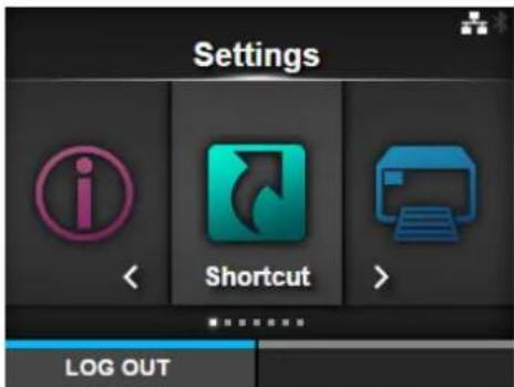
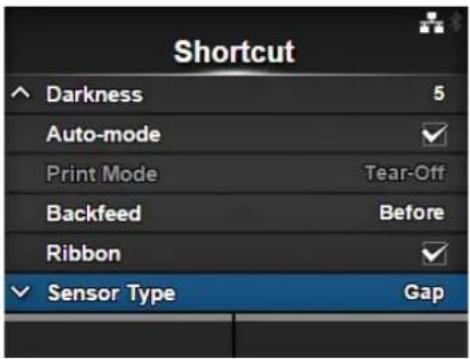
4.4.1 Shortcut Menu
Frequently used settings are listed in the Shortcut menu.
| Shortcut | |||
| 1 Adjustments Correct the offset, print position and print darkness. | 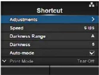 | ||
| 2 Speed Set the print speed. | |||
| 3 Darkness Range Set the range of the print darkness. | |||
| 4 Darkness Set the print darkness. | |||
| 5 Auto-mode Automatically set the print mode. | |||
| 6 Print Mode Manually set the print mode. | |||
| 7 Backfeed Set the backfeed operation. | |||
| 8 Ribbon Set whether to print using a ribbon or direct thermal media. | |||
| 9 Sensor Type Set the media sensor type. | |||
| 10 Head Check Check if there is a broken element of the print head. | |||
| 11 Help Shows the guidance video. | |||
4.4.2 Printing Menu
The following settings are available in the Printing menu:
| Printing | |||
| 1 Label Length Set the length of the media. | 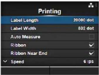 | ||
| 2 Label Width Set the width of the media. | |||
| 3 Auto Measure Automatically measure the length of the media. | |||
| 4 Ribbon Set whether to print using a ribbon or direct thermal media. | |||
| 5 Ribbon Near End Enable or disable the warning when the ribbon is about to run out.*Shows only if you have selected Use Ribbon in the Ribbon menu. | |||
| 6 Speed Set the print speed. | |||
| 7 Sensor Type Set the media sensor type. | |||
| 8 Auto-mode Automatically set the print mode. | |||
| 9 Print Mode Manually set the print mode. | |||
| 10 Backfeed Set the back feed operation. | |||
| 11 Eject Cut Set the time from the print completion until the print cut.*Shows only if you have selected Cut & Print in the Print Mode menu. | |||
| 12 Darkness Range | Set the range of the print darkness. | ||
| 13 Darkness Set the print darkness. | |||
| 14 Imaging Set the print reference position in the vertical and horizontal directions. | |||
| 15 Advanced Set the sensor operation and print motion. | |||
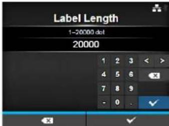
Label Length
Printing > Label Length
Set the length of the media.
The setting range varies depending on the print resolution of the printer.
The setting range of the label length is as follows:
• 203 dpi: 1 to 20000 dots
• 305 dpi: 1 to 18000 dots
• 609 dpi: 1 to 9600 dots
• 203 dpi: 1 to 20000 dots
• 305 dpi: 1 to 18000 dots
Note
Set the label size to a value that includes the liner.
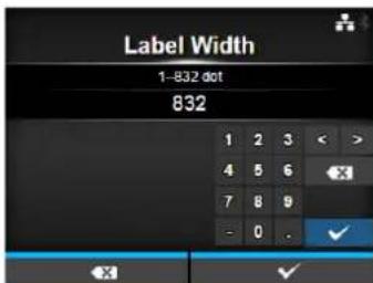
Label Width
Printing > Label Width
Set the width of the media.
The setting range varies depending on the print resolution of the printer.
The setting range of the label width is as follows:
• 203 dpi: 1 to 832 dots
• 305 dpi: 1 to 1248 dots
• 609 dpi: 1 to 2496 dots
if Head Base Position is Standard
• 203 dpi: 1 to 1216 dots
• 305 dpi: 1 to 1984 dots
if Head Base Position is Left-justify
• 203 dpi: 1 to 1340 dots
• 305 dpi: 1 to 2010 dots
Note
Set the label size to a value that includes the liner.
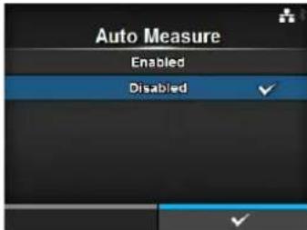
Auto Measure
Printing > Auto Measure
The printer automatically measures the length of the media.
The measured length of the media will be automatically saved in Label Length.
Available when you have selected Gap or I-Mark in the Sensor Type menu.
The setting procedure of the label length using the Auto Measure function is as follows:
- Load the media.
- Set Auto Measure to Enabled.
- Press the button or button to show the online or offline screen.
- Open the print head. (Head Open error occurs)
- Close the print head. (Returns to offline screen)
- When you press the button, the printer feeds two pieces of label and measures the label length.
- The measured label length will be saved in Label Length.
Note
When you have set Auto Measure to Enabled, this function executes when the printer powers on.
Ribbon
Printing > Ribbon
Set whether to print using a ribbon or direct thermal media.
The options are as follows:
- Use Ribbon: Print with a ribbon.
- Direct Thermal: Print using direct thermal media.
Ribbon Near End
Printing > Ribbon Near End
Show or do not show the warning icon when the ribbon is about to run out.
Shows only if you have selected Use Ribbon in the Ribbon menu.
The options are as follows:
- Enabled: Show the warning icon.
- Disabled: Do not show the warning icon.
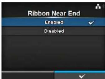
Note
The warning icon shows in the status bar on the upper part of the screen.
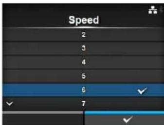
Speed
Printing > Speed
The setting range varies depending on the print resolution of the printer. The setting range of the print speed is as follows:
• 203 dpi: 2 to 10 ips (inches/sec)
• 305 dpi: 2 to 8 ips (inches/sec)
• 609 dpi: 2 to 6 ips (inches/sec)
If the optional linerless kit is installed, the setting range will be from 2 to 6 ips (inches/sec) regardless of the print resolution of the printer. If Speed is set to 7 ips and above, it will change to 4 ips after the optional linerless kit is installed.
- 203 dpi: 2 to 10 ips (inches/sec)
• 305 dpi: 2 to 8 ips (inches/sec)
Note
Setting the print speed to a level that is too fast may affect the print quality.
Sensor Type
Printing > Sensor Type
Set the type of sensor for sensing the media. The options are as follows:
- None: Disable the media sensor.
- Gap: Use the transmissive type sensor.
- I-Mark: Use the reflective type sensor.
If you have selected Tear-Off, Dispenser or Cut & Print in Print Mode, only Gap and I-Mark will be available in the Sensor Type menu. If you have selected Linerless in Print Mode (CL4NX only), only None and I-Mark will be available in the Sensor Type menu.
Auto-mode
Printing > Auto-mode
When using Auto-mode, the print mode changes automatically according to the status of the installed option unit.
The options are as follows:
- Enabled: The print mode changes automatically.
- Disabled: The print mode changes according to the setting of the Print Mode.
Operate in cutter mode if you have installed the optional cutter unit. Operate in dispenser mode if you have installed the optional dispenser unit.
Operate in linerless mode if you have installed the optional linerless kit (CL4NX only).
Print Mode
Printing > Print Mode
Set the print mode.
The options are as follows:
- Continuous: Print the specified number of media. The media remains in position for printing at all times.
- Tear-Off: After printing the specified number of media, the printer feeds the last printed media so that it is fully extended out of the printer's front for removal. After printing, tear off the media manually.
- Cutter: Cut each media while printing the specified number of media. You can specify this option only if you have installed the cutter unit.
- Cut & Print: Cut the last printed media while printing media with next data. If next data is not received within the period specified in Eject Cut, the printer will feed the media to the cut position and cut the last printed media. You can specify this option only if you have installed the cutter unit.
- Dispenser: Peel the liner from the printed label as it is advanced to the printer's front. Once the printed label has been removed from the printer for application, the next label will retract and position itself for printing. You can specify this option only if you have installed the dispenser unit.
- Linerless (CL4NX only): Cut each label while printing the specified number of labels. You can specify this option only if you have installed the linerless kit.
If no option is installed, Continuous and Tear-Off are available in the Print Mode menu.
If the optional cutter unit is installed, Continuous, Tear-Off, Cutter and Cut & Print are available in the Print Mode menu.
If the optional dispenser unit is installed, Continuous, Tear-Off and Dispenser are available in the Print Mode menu.
If the optional linerless kit is installed, only Linerless is available in the Print Mode menu.
If no option is installed, Continuous and Tear-Off are available in the Print Mode menu.
If the optional cutter unit is installed, Continuous, Tear-Off, Cutter and Cut & Print are available in the Print Mode menu.
If the optional dispenser unit is installed, Continuous, Tear-Off and Dispenser are available in the Print Mode menu.
Note
You cannot set the Print Mode if Auto-mode is Enabled.
Backfeed
Printing > Backfeed
Backfeed is applicable only when the print mode is set to tear-off mode, cutter mode, dispenser mode or linerless mode (CL4NX only).
The options are as follows:
• None: Do not backfeed.
- After: After cut, backfeed the front part of the next media to the print head position. For dispenser mode, backfeed the front part of the next label after dispensing the label.
- Before: Before printing, backfeed the front part of the media to the print head position.
If you have selected Tear-Off or Linerless (CL4NX only) in Print Mode, only Before is available in the Backfeed menu.
Eject Cut
Printing > Eject Cut
Set the Eject cut motion for the last printed media. Cut the last media after the specified timing.
Shows only when you have selected Cut & Print in the Print Mode menu. The setting range is from 0 to 5 (sec).
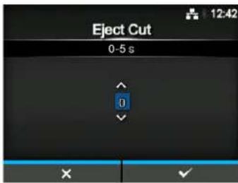
Darkness Range
Printing > Darkness Range
Set the range of the print darkness.
The darkness range affects the print darkness.
The options are as follows:
A, B, C, D, E, F
*The normal setting is A. You can also select B to F but the print darkness does not change.
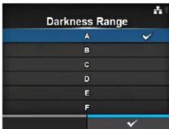
Darkness
Printing > Darkness
Specify the print darkness from ten steps.
The setting range is from 1 to 10. 1 is the lightest and 10 is the darkest.
To further fine tune the print darkness, set the items in Printing > Advanced > Adjustments > Darkness Adjust.
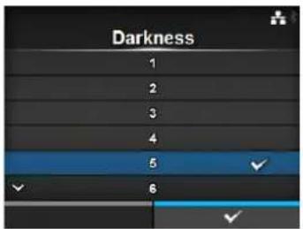
Imaging
Printing > Imaging
Set the print reference position in the vertical and horizontal directions. The setting items are as follows:
| 1 Vertical Offset the print position in the vertical (feed) direction. | |
| 2 Horizontal Offset the print position in the horizontal direction. |
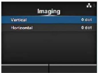
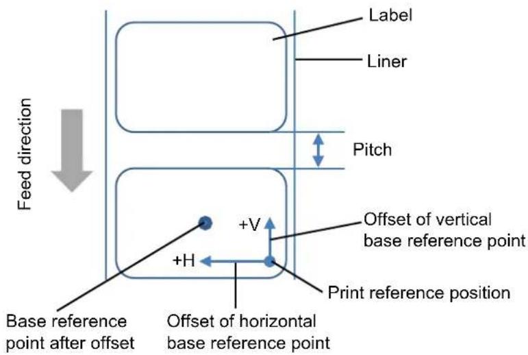
Vertical
Printing > Imaging > Vertical
Set the print position in the vertical direction.
Set the offset value '+' from the print reference position to move the print position opposite the feed direction and value '-' to move the print position in the feed direction.
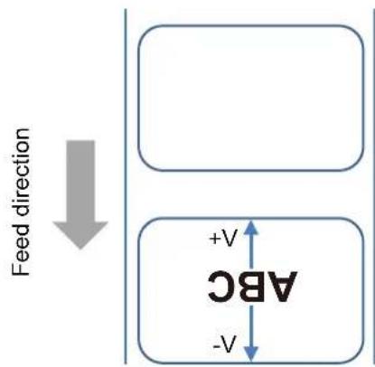
The setting range is from -792 to +792 dots.
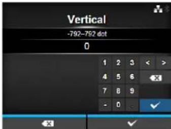
Horizontal
Printing > Imaging > Horizontal
Set the print position in the horizontal direction.
Set the offset value '+' from the print reference position to move to the left side and value '-' to move to the right side of the printer (when facing the front of the printer).
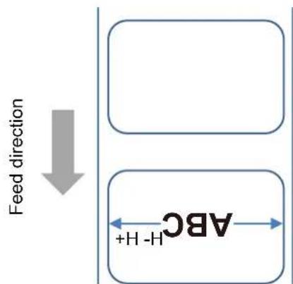
The setting range is from -792 to +792 dots.
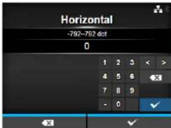
| Advanced | |||
| Printing > AdvancedSet detailed sensor operation and print motion.The setting items are as follows: | 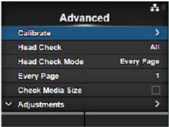 | ||
| 1 | Calibrate | Adjust the media sensor. | |
| 2 | Head Check | Check if there is a broken element of the print head. | |
| 3 | Head Check Mode | Set the mode for head check.*Shows only if you have selected All or Barcode in the Head Check menu. | |
| 4 | Every Page | Set the interval for head check.*Shows only if you have selected Every Page in the Head Check Mode menu. | |
| 5 | Check Media Size Enable or disable media size check.*Shows only if you have selected Gap or I-Mark in the Sensor Type menu. | ||
| 6 | Adjustments Correct the offset, print position and print darkness. | ||
| 7 | Start Online | Start in online mode at power on. | |
| 8 | Feed After Error | Feeds the media when an error occurs. | |
| 9 | Feed At Power On | Automatically feeds the media at power on. | |
| 10 | Finisher Feed | Set the length to feed after printing. | |
| 11 | Paper End | Select the sensor for sensing the paper end. | |
| 12 | Head Base Position | Set the edge position for printing. | |
| 13 | Prioritize | Select the prioritized setting. | |
| 14 | Reprint | Enable or disable the reprint function. | |
| 15 | Print End Position | Set the print end position of the media. | |
| 16 | Label Near End | Enable or disable the warning when the media is about to run out.*This printer does not support the Label Near End function. Keep the setting disabled. | |
| Calibrate | |||
| Printing > Advanced > CalibrateAdjust the media sensor level.In instances of media detection malfunction, adjust the media sensor level (Gap and I-mark sensor).The setting items are as follows: | 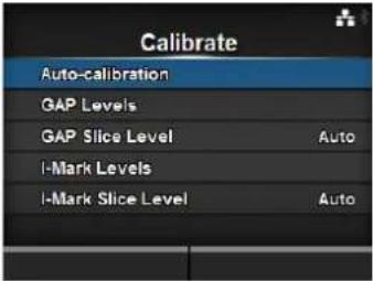 | ||
| 1 Auto-calibration Automatically adjust the sensor level.*Does not show if you have installed the optional linerless kit (CL4NX only). | |||
| 2 GAP Levels Manually set the Gap sensor level. | |||
| 3 GAP Slice Level Manually set the Gap sensor slice level. | |||
| 4 I-Mark Levels Manually set the I-mark sensor level. | |||
| 5 I-Mark Slice Level Manually set the I-mark sensor slice level. | |||
Auto-calibration
Printing > Advanced > Calibrate > Auto-calibration
Perform the auto-calibration for the selected media sensor.
Auto-calibration is not available if you have installed the optional linerless kit (CL4NX only).
- Gap + I-Mark: Perform the adjustment for both the Gap sensor and I-mark sensor.
- Gap: Perform the adjustment for the Gap sensor.
- I-Mark: Perform the adjustment for the I-mark sensor.
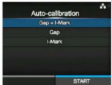
Procedure:
- Push the head lock lever towards the rear to unlock the print head.
- Pass the media below the media sensor guide. If you are using labels, remove the label from the liner. Align it so that the media sensor does not sense the I-mark (black mark).
- Press the print head down until the head lock lever is locked. To get the correct adjustment result, adjust after you have locked the print head.
- Press the ▲/▼ buttons to select the type of sensor to be adjusted.
- Press the right soft button or ← button to start the sensor adjustment.
- The sensor adjustment result shows. To exit the adjustment, press the right soft button.
- Set to offline mode. Press the right soft button to confirm that the media feeds correctly.
Note
If the media does not feed correctly after Auto-calibration, contact your SATO reseller or technical support center.
GAP Levels
Printing > Advanced > Calibrate > GAP Levels
Manually set the Gap sensor level.
The setting procedure is as follows:
First, adjust the "Low" level (voltage) of the Gap sensor.
- Remove the label from the liner.
- Pass the liner through the media sensor. Align it so that the media sensor does not sense the I-mark (black mark).
-
Close the print head. To get the correct adjustment result, adjust after you have closed the print head.
-
Select the GAP Levels in the Calibrate menu and press the ← button.
-
Press the ▲/▼ buttons to change the Emit value until the Sensor value is below 0.5 (V). Set the Emit value as low as possible.
-
If the Sensor value does not decrease below 0.5 after you changed the Emit value, press the ◀/▶ buttons to change the Receive value.
-
Take a note of the Sensor value from the above procedure. This is the "Low" level value for the Gap sensor.
Next, check the "High" level (voltage) of the Gap sensor as follows:
- Pass the media (attached with liner) between the media sensors. Align it so that the media sensor does not sense the l-mark (black mark).
- Close the print head.
- Check the Sensor value.
If the value is 1.0 (V) higher than the “Low” level value you have recorded, then this is the “High” level value for the Gap sensor. If the difference between the “High” and the “Low” levels is less than 1.0, adjust the Emit and Receive values so that the difference is more than 1.0, or perform the adjustments again from step 1. The standard values for the “High” and “Low” levels for the Gap sensor are as follows:
-
Low (with only liner) ≤ 0.5 (V)
• High (media attached with liner) - Low ≥ 1.0 (V) -
If both "High" and "Low" levels comply with the standard value, press the right soft button to confirm the value.
![GAP Levels Sensor: 0.1 ▲▼ Emit: 3 [0, 7] ◀▶ Receive: 57 [0, 127]](/content/2026/05/1069167/images/8f37dc13e51212ea0343193310a0c33de018d29bc2baa852c068d3261f62b279.jpg)
GAP Slice Level
Printing > Advanced > Calibrate > GAP Slice Level
Set the Gap sensor slice level.
The setting procedure is as follows:
- Use the following formula to calculate the slice level. [(High level - Low level) x 0.3 + Low level = slice level]
-
Select the GAP Slice Level in the Calibrate menu and press the ← button.
-
Press the ▲/▼ buttons to change the Slice level value. Set the Slice level to the level calculated in step 1.
-
Press the right soft button to confirm the value.
Note
If you set the Slice Level to 0.0 (V), the printer sets the slice level automatically.
![GAP Slice Level Sensor: 0.1 ▲▼ Slice level 0.0 V [0.0, 3.3]](/content/2026/05/1069167/images/a17fbf268c55db7f832e65727609d0de2a2d145758335f875757b394136cd8c6.jpg)
I-Mark Levels
Printing > Advanced > Calibrate > I-Mark Levels
Manually set the I-mark sensor level.
The setting procedure is as follows:
First, adjust the "Low" level (voltage) of the I-mark sensor.
- Pass the media (attached with liner) between the media sensors. Align it so that the media sensor does not sense the l-mark (black mark).
- Close the print head. To get the correct adjustment result, adjust after you have closed the print head.
- Select the I-Mark Levels in the Calibrate menu and press the button.
- Press the ▲/▼ buttons to change the Emit value until the Sensor value is below 0.5 (V). Set the Emit value as low as possible.
- If the Sensor value does not decrease below 0.5 after you changed the Emit value, press the ◀/▶ buttons to change the Receive value.
- Take a note of the Sensor value from the above procedure. This is the "Low" level value for the l-mark sensor.
Next, check the "High" level (voltage) of the I-mark sensor as follows: - Pass the media between the media sensors so that the media sensor can sense the I-mark (black mark).
- Close the print head.
- Check the Sensor value.
If the value is 1.0 (V) higher than the “Low” level value you have recorded, then this is the “High” level value for the I-mark sensor. If the difference between the “High” and the “Low” levels is less than 1.0, adjust the Emit and Receive values so that the difference is more than 1.0, or perform the adjustments again from step 1. The standard values for the “High” and “Low” levels for the I-mark sensor are as follows:
-
Low (without I-mark) ≤ 0.5 (V)
• High (with I-mark) - Low ≥ 1.0 (V) -
If both "High" and "Low" levels comply with the standard value, press the right soft button to confirm the value.
![I-Mark Levels Sensor: 3.1 ▲▼ Emit: 2 [0, 7] ◀▶ Receive: 43 [0, 127]](/content/2026/05/1069167/images/0ffb1849dd5c0dbd1b9e33268558c5e3e21a0540d502868627927b05b920b114.jpg)
I-Mark Slice Level
Printing > Advanced > Calibrate > I-Mark Slice Level
Set the I-mark sensor slice level.
The setting procedure is as follows:
- Use the following formula to calculate the slice level. [(High level - Low level) x 0.7 + Low level = slice level]
- Select the I-Mark Slice Level in the Calibrate menu and press the

-
Press the ▲/▼ buttons to change the Slice level value. Set the Slice level to the slice level calculated in step 1.
-
Press the right soft button to confirm the value.
Note
If you set the Slice Level to 0.0 (V), the printer sets the level automatically.
![I-Mark Slice Level Sensor: 3.1 ▲ ▼ Slice level: 0.0 V [0.0, 3.3]](/content/2026/05/1069167/images/0088de39499bddbdab92a6d60cede1b23326467d145dc4eabca31400eaef34f1.jpg)
Head Check
Printing > Advanced > Head Check
Automatically check if there is a broken element of the print head.
The options are as follows:
- Off: Head Check disabled.
- All: Check the entire print area.
- Barcode: Check only the area for printing a barcode. Head check is not applicable for barcodes printed as graphic data.
CAUTION
Head check is a reference for checking for a broken element of the print head. This function does not guarantee barcode readability.
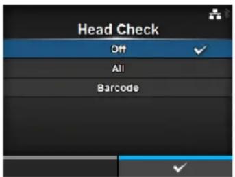
Head Check Mode
Printing > Advanced > Head Check Mode
Set the method for head check.
Shows only if you have selected All or Barcode in the Head Check menu.
The options are as follows:
- Always: Perform the head check for every item.
- After Batch: The head check occurs before starting to print and when printing is stopped. If backfeed is applicable, the head check occurs before starting to print, when stopping to print and during the backfeed.
- Every Page: Perform the head check for each specified number of media.

Every Page
Printing > Advanced > Every Page
Specify the number of media between each head check.
Shows only if you have selected Every Page in the Head Check Mode menu.
The setting range is from 1 to 999999.
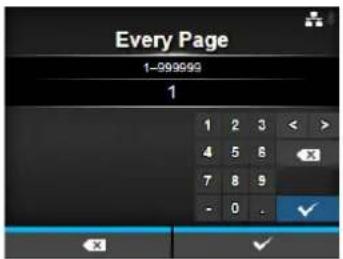
Check Media Size
Printing > Advanced > Check Media Size
Enable or disable media size check.
Media size check is a function to detect a Media error when you load a media with a length longer than the media size specified by command, or if you have specified print data larger than the loaded media length.
Shows only if you have selected Gap or I-Mark in the Sensor Type menu.
The options are as follows:
- Enabled: Enable media size check.
- Disabled: Disable media size check.
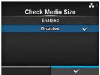
Adjustments
Printing > Advanced > Adjustments
Correct the offset position, print position and print darkness.
The setting items are as follows:
1 Offset Correct the offset position.
2 Pitch Offset the print position in the vertical direction.
3 Darkness Adjust Fine tune the print darkness.
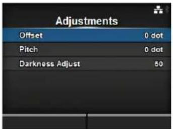
Offset
Printing > Advanced > Adjustments > Offset
Correct the offset position.
Offset position refers to the tear-off position, cut position and dispense stop position.
Set the offset value '+' to move the stop position opposite the feed direction and value '-' to move the stop position in the feed direction.
The setting range varies depending on the print resolution of the printer.
The setting range is as follows:
• 203 dpi: -30 to 0 to 30 dots
• 305 dpi: -45 to 0 to 45 dots
• 609 dpi: -90 to 0 to 90 dots
- 203 dpi: -30 to 0 to 30 dots
• 305 dpi: -45 to 0 to 45 dots
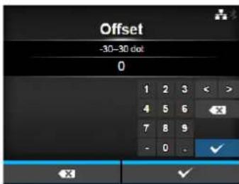
Pitch
Printing > Advanced > Adjustments > Pitch
Offset the print position in the vertical direction.
Set the offset value '+' to move the print position opposite the feed direction and value '-' to move the print position in the feed direction.
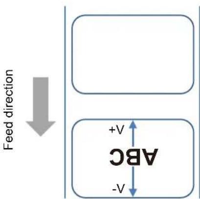
The setting range varies depending on the print resolution of the printer.
The setting range is as follows:
• 203 dpi: -30 to 0 to 30 dots
• 305 dpi: -45 to 0 to 45 dots
• 609 dpi: -90 to 0 to 90 dots
• 203 dpi: -30 to 0 to 30 dots
• 305 dpi: -45 to 0 to 45 dots
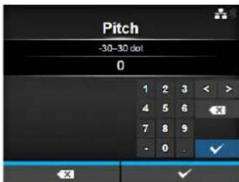
Darkness Adjust
Printing > Advanced > Adjustments > Darkness Adjust
Fine tune the print darkness.
The setting range is from 0 to 99.
0 is the lightest and 99 is the darkest.
Refer to Darkness in Printing > Darkness.
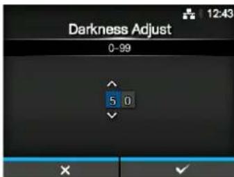
Start Online
Printing > Advanced > Start Online
Select default mode at power on.
The options are as follows:
- Enabled: The printer powers on in online mode.
- Disabled: The printer powers on in offline mode.
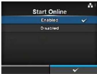
Feed After Error
Printing > Advanced > Feed After Error
Automatically feeds the media when recovering from an error and changing to online mode.
The options are as follows:
- Enabled: Feed the media when changing to online mode after recovering from an error.
- Disabled: Do not feed the media when changing to online mode after recovering from an error.
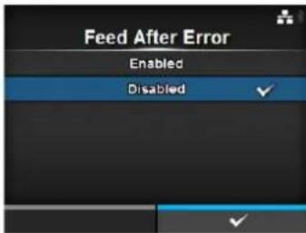
Feed At Power On
Printing > Advanced > Feed At Power On
Automatically feeds the media at power on.
The options are as follows:
- Enabled: Feed the media when the printer is powered on.
- Disabled: Do not feed the media when the printer is powered on.
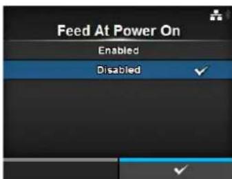
Finisher Feed
Printing > Advanced > Finisher Feed
Set the media feed amount for Tear-off, cut and dispense stop. Set the media feed amount based on the print head position of 0. The actual media feed amount is the value of Offset + Finisher Feed. The setting range varies depending on the print resolution of the printer. The setting range is as follows:
• 203 dpi: 0 to 2040 dots
• 305 dpi: 0 to 3060 dots
• 609 dpi: 0 to 6120 dots
• 203 dpi: 0 to 2040 dots
• 305 dpi: 0 to 3060 dots
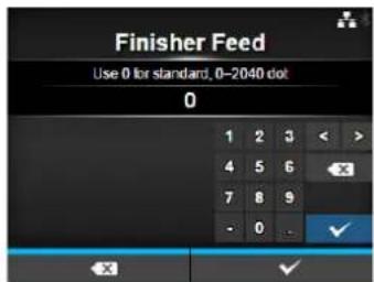
Paper End
Printing > Advanced > Paper End
Select the sensor for sensing the paper end. The options are as follows:
- Using I-mark: Use the I-mark sensor (reflective type) to sense the paper end.
- Using Gap: Use the Gap sensor (transmissive type) to sense the paper end.
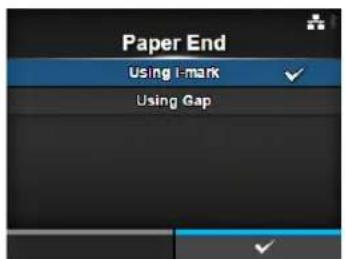
Head Base Position
Printing > Advanced > Head Base Position
Set the position used for the base reference point for printing. The options are as follows:
- Standard: Print with a standard base reference point.
- Left-justify: Move the base reference point 2 mm (0.08") to the left (when you face the printer).
- Standard: Print with a standard base reference point.
- Left-justify: Move the base reference point 2 mm (0.08") to the left (when you face the printer). Expand the width of the printable area. Refer to Printable Area in Section 7.6.1 Hardware for details.
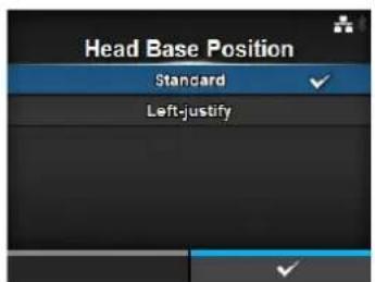
Note
The message prompting to restart the printer will appear on the online/offline screen if you have made any changes. In such a case, reboot the printer to make the setting effective.
Prioritize
Printing > Advanced > Prioritize
For printer configuration, set whether to prioritize the setting through the printer or prioritize the setting through the command.
The options are as follows:
- Commands: Prioritize the setting through the command.
- Settings: Prioritize the setting through the printer.
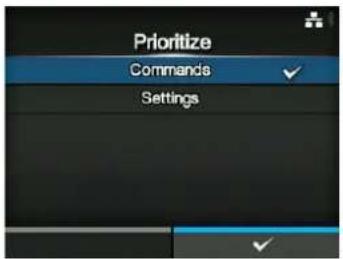
Reprint
Printing > Advanced > Reprint
Enable or disable the reprint function.
The options are as follows:
- Enabled: Enable the reprint function.
- Disabled: Disable the reprint function.
If you have selected Enabled in Reprint, you can press the right soft button (Reprint) on the online screen to print the previous data again.
Note
The previous data will be lost if you power off the printer.
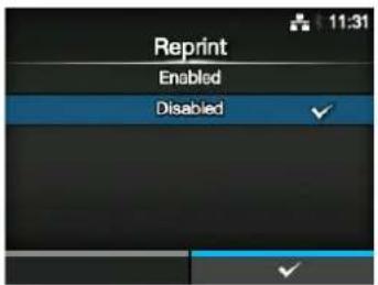
Print End Position
Printing > Advanced > Print End Position
Adjust the media stop position or cut position when the sensor type is set to None. This adjustment also sets the blank amount from the media stop position.
The setting range varies depending on the print resolution of the printer.
The setting range is as follows:
• 203 dpi: 0 to 20000 dots
• 305 dpi: 0 to 18000 dots
• 609 dpi: 0 to 9600 dots
• 203 dpi: 0 to 20000 dots
• 305 dpi: 0 to 18000 dots
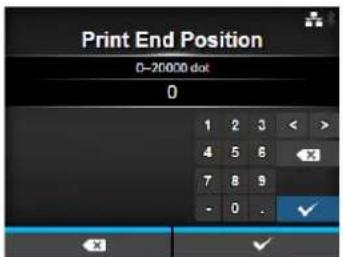
Label Near End
Printing > Advanced > Label Near End
Show or do not show the warning icon when the media is about to run out.
The options are as follows:
- Enabled: Show the warning icon.
- Disabled: Do not show the warning icon.
Note
This printer does not support the Label Near End function. Keep the setting disabled.
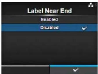
4.4.3 Interface Menu
In the Interface menu, the setting items are as follows:
| Interface | |||
| 1 Network Set the LAN connection and wireless LAN connection. | 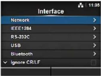 | ||
| 2 IEEE1284 Set the IEEE 1284 connection.*Shows only if the combo interface board is installed. | |||
| 3 RS-232C Set the RS-232C connection.*Shows only if the combo interface board is installed. | |||
| 4 USB Set the USB connection. | |||
| 5 Bluetooth Set the Bluetooth connection. | |||
| 6 Ignore CR/LF Set to ignore CR/LF codes. | |||
| 7 Ignore CAN/DLE Set to ignore CAN/DLE codes. | |||
| 8 External I/O Set the external signal (EXT).*Shows only if the combo interface board is installed. | |||
| 9 R F I D (CL4NX only) | Set the RFID.*Shows only for RFID models. | ||
| Network | |||
| Interface > NetworkTo use LAN and wireless LAN for the interface between the host and the printer.The setting items are as follows: | 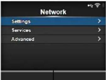 | ||
| 1 Settings Set the LAN, wireless LAN or select the interface. | |||
| 2 Services Set the TCP/IP port number, NTP, LPD, FTP or SNMP. | |||
| 3 Advanced Set the advanced function for the interface. | |||
| Settings | |||
| Interface > Network > SettingsSet the LAN, wireless LAN or select the interface.The setting items are as follows: | 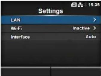 | ||
| 1 LAN Set the LAN. | |||
| 2 Wi-Fi Set the wireless LAN. | *Shows only if you have installed the optional wireless LAN. | ||
| 3 Interface Select the network interface.*This item is to select the network interface from LAN or wireless LAN when you have installed the optional wireless LAN. | |||
| CAUTIONYou cannot use LAN and wireless LAN at the same time. The wireless LAN function is available only if you have installed the wireless LAN. | |||
| LAN | |||
| Interface > Network > Settings> LANSet the IPv4, IPv6 or proxy for the LAN.The setting items are as follows: | 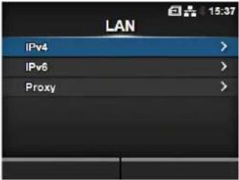 | ||
| 1 IPv4 Set the IPv4 for the LAN. | |||
| 2 IPv6 Set the IPv6 for the LAN. | |||
| 3 Proxy Set the proxy for the LAN. | |||
| IPv4 | |||
| Interface > Network > Settings> LAN > IPv4Set IPv4 for the LAN. The setting items are as follows: | 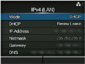 | ||
| 1 Mode Select the IP address assignment method. | |||
| 2 DHCP / Renew Lease | Update the lease time and get the IP address from the DHCP server again.*Shows only if you have selected DHCP in the Mode menu and LAN is the active interface.*Does not show if WLAN is the active interface. | ||
| 3 IP Address Set and check the IP address.If you have selected DHCP in the Mode menu, the screen shows the IP address you received from the DHCP server.If you have selected Static in the Mode menu, select to set the IP address. | |||
| 4 Netmask Set and check the subnet mask address.If you have selected DHCP in the Mode menu, the screen shows the subnet mask address you received from the DHCP server.If you have selected Static in the Mode menu, select to set the subnet mask address. | |||
| 5 Gateway Set and check the default gateway address.If you have selected DHCP in the Mode menu, the screen shows the gateway address you received from the DHCP server.If you have selected Static in the Mode menu, select to set the default gateway address. | |||
| 6 DNS Set and check DNS server addresses.If you have selected Static in the Mode menu, select to set and check DNS server addresses. | |||
| CAUTIONAfter setting, press the right soft button to enable the new setting. Press the left soft button to cancel the new setting and return to the previous setting.NoteYou cannot change IP Address, Netmask, Gateway and DNS if Mode is DHCP. | |||
Mode
Interface > Network > Settings > LAN > IPv4 > Mode
Select the IP address assignment method.
The options are as follows:
- DHCP: Automatically retrieve the IP address, gateway and subnet mask from the DHCP server.
- Static: Manually set the IP address, gateway and subnet mask.
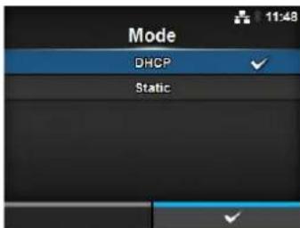
IP Address
Interface > Network > Settings > LAN > IPv4 > IP Address
If you have selected Static in the Mode menu, set the IP address.
The setting range is as follows:
000.000.000.000 to 255.255.255.255
Netmask
Interface > Network > Settings > LAN > IPv4 > Netmask
If you have selected Static in the Mode menu, set the subnet mask address.
Each group of the address can be set cyclically among 0, 128, 192, 224, 240, 248, 252, 254 and 255.
The setting range is as follows:
128.000.000.000 to 255.255.255.254

Gateway
Interface > Network > Settings > LAN > IPv4 > Gateway
If you have selected Static in the Mode menu, set the default gateway address.
The setting range is as follows:
000.000.000.000 to 255.255.255.255
DNS
Interface > Network > Settings > LAN > IPv4 > DNS
If you have selected Static in the Mode menu, set and check DNS server addresses.
The setting range is as follows: 000.000.000.000 to 255.255.255.255
Note
You can register up to three IP addresses for the DNS server. Use a comma to delimit different IP addresses.
| IPv6 | |||
| Interface > Network > Settings > LAN > IPv6Set IPv6 for the LAN. The setting items are as follows: |  | ||
| 1 Mode Select the IP address assignment method. | |||
| 2 DHCP / Renew Lease | Update the lease time and get the IP address from the DHCP server again.*Shows only if you have selected DHCP in the Mode menu.*Does not show if WLAN is the active interface. | ||
| 3 IP Address Set and check the IP address.If you have selected DHCP in the Mode menu, the screen shows the IP address you received from the DHCP server.If you have selected Static in the Mode menu, select to set the IP address. | |||
| 4 Prefix Length Set and check the prefix. | |||
| 5 Gateway Set and check the default gateway address.If you have selected DHCP in the Mode menu, the screen shows the gateway address you received from the DHCP server.If you have selected Static in the Mode menu, select to set the default gateway address. | |||
| 6 DNS Set and check the address of the primary DNS server.If you have selected Static in the Mode menu, select to set the primary address of the DNS server. | |||
| CAUTIONAfter setting, press the right soft button to enable the new setting. Press the left soft button to cancel the new setting and return to the previous setting. | |||
| NoteYou cannot change IP Address, Prefix Length, Gateway and DNS if Mode is DHCP or Auto. | |||
Mode
Interface > Network > Settings > LAN > IPv6 > Mode
Select the IP address assignment method.
The options are as follows:
- Auto: Automatically generate the IP address and gateway (stateless mode).
- DHCP: Automatically retrieve the IP address and gateway from the DHCP server automatically (stateful mode).
- Static: Manually set the IP address, gateway and subnet mask.
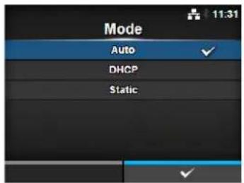
IP Address
Interface > Network > Settings > LAN > IPv6 > IP Address
If you have selected Static in the Mode menu, set the IP address.
The setting range is as follows:
0:0:0:0:0:0:0:1 to ffff:ffff:ffff:ffff:ffff:ffff:ffff
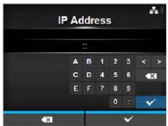
Prefix Length
Interface > Network > Settings > LAN > IPv6 > Prefix Length
If you have selected Static in the Mode menu, set the prefix.
The setting range is from 1 to 128.
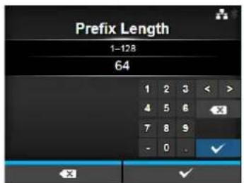
Gateway
Interface > Network > Settings > LAN > IPv6 > Gateway
If you have selected Static in the Mode menu, set the default gateway address.
The setting range is as follows:
0:0:0:0:0:0:0:0 to ffff:ffff:ffff:ffff:ffff:ffff:ffff
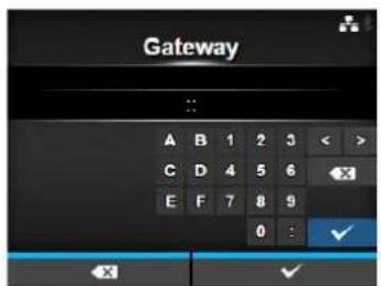
DNS
Interface > Network > Settings > LAN > IPv6 > DNS
If you have selected Static in the Mode menu, set the primary address of the DNS server.
The setting range is as follows: 0:0:0:0:0:0:0:0 to ffff:ffff:ffff:ffff:ffff:ffff:ffff
Note
You can register only one IP address for the DNS server for IPv6.
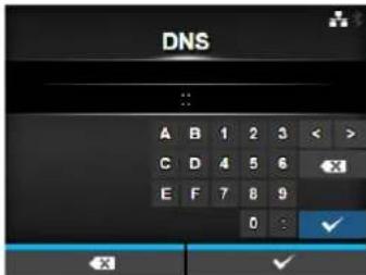
Proxy
Interface > Network > Settings > LAN > Proxy
Set the proxy for the LAN. The setting items are as follows:
1 Enabled Enable or disable use of proxy.
2 Server Set the proxy server address.
3 Exclude Exclude the proxy from usage.
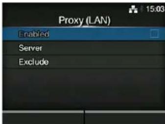
Enabled
Interface > Network > Settings > LAN > Proxy > Enabled
Enable or disable use of proxy.
The options are as follows:
- Enabled: Enable proxy server usage.
- Disabled: Disable proxy server usage.
Note
To enable the proxy, Server should be set and Exclude must contain at least 127.0.0.1 and localhost.

Server
Interface > Network > Settings > LAN > Proxy > Server
Set the name or IP address of the proxy server.
Note
Server should be set with a valid name or IP address and port number.
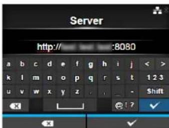
Exclude
Interface > Network > Settings > LAN > Proxy > Exclude
Set names, IP addresses or domains for the proxy to exclude.
Note
Exclude must contain at least 127.0.0.1 and localhost.
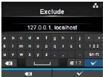
Wi-Fi
Interface > Network > Settings > Wi-Fi
Set the wireless LAN.
Shows only if you have installed the optional wireless LAN.
The setting items are as follows:
1 IPv4 Configure IPv4 for Wi-Fi.
2 IPv6 Configure IPv6 for Wi-Fi.
3 Proxy Configure the proxy for Wi-Fi.
4 Wi-Fi Protected Setup Set the wireless LAN connection with the WPS function.
5 Wi-Fi Direct Set the Wi-Fi Direct function.
*Enabled only if you have selected Infrastructure in the Mode menu.
6 SSID Set the SSID.
7 Hidden SSID Set the Hidden SSID.
8 Mode Set the communication mode.
9 Channel Set the communication channel.
10 Security Set the security (encryption method).
11 WEP Conf. Set the WEP key.
*Shows only if you have selected WEP in the Security menu.
12 WPA Conf.
Set the WPA authentication.
*Shows only if you have selected WPA+WPA2 or WPA2 in the Security menu.
13 EAP Conf. Set the EAP authentication.
*Shows only if you have selected Dynamic WEP in the Security menu.
Note
When Wi-Fi Direct is active, only IPv6 is not shown on the screen.
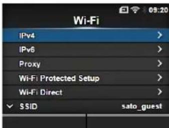
| IPv4 | |||
| Interface > Network > Settings> Wi-Fi > IPv4Configure IPv4 for Wi-Fi. The setting items are as follows: | 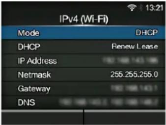 | ||
| 1 Mode Select the IP address assignment method. | |||
| 2 DHCP / Renew Lease | Update the lease time and get the IP address from the DHCP server again.*Shows only if you have selected DHCP in the Mode menu.*Does not show if LAN is the active interface. | ||
| 3 IP Address Set and check the IP address.If you have selected DHCP in the Mode menu, the screen shows the IP address you received from the DHCP server.If you have selected Static in the Mode menu, select to set the IP address. | |||
| 4 Netmask Set and check the subnet mask address.If you have selected DHCP in the Mode menu, the screen shows the subnet mask address you received from the DHCP server.If you have selected Static in the Mode menu, select to set the subnet mask address. | |||
| 5 Gateway Set and check the default gateway address.If you have selected DHCP in the Mode menu, the screen shows the gateway address you received from the DHCP server.If you have selected Static in the Mode menu, select to set the default gateway address. | |||
| 6 DNS Set and check DNS server addresses.If you have selected Static in the Mode menu, select to set and check DNS server addresses. | |||
| CAUTIONAfter setting, press the right soft button to enable the new setting. Press the left soft button to cancel the new setting and return to the previous setting.NoteWhen Wi-Fi Direct is active, Mode, DHCP and DNS are not shown. In addition, you cannot change IP Address, Netmask and Gateway if Mode is DHCP or Wi-Fi Direct is active. DNS cannot be changed if Mode is DHCP. | |||
Mode
Interface > Network > Settings > Wi-Fi > IPv4 > Mode
Select the IP address assignment method.
The options are as follows:
- DHCP: Automatically retrieve the IP address, gateway and subnet mask from the DHCP server.
- Static: Manually set the IP address, gateway and subnet mask.
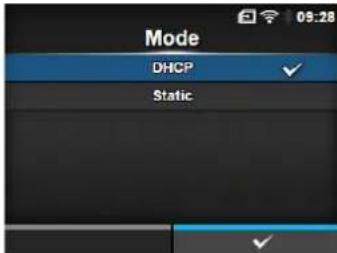
IP Address
Interface > Network > Settings > Wi-Fi > IPv4 > IP Address
If you have selected Static in the Mode menu, set the IP address.
The setting range is as follows:
000.000.000.000 to 255.255.255.255
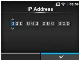
Netmask
Interface > Network > Settings > Wi-Fi > IPv4 > Netmask
If you have selected Static in the Mode menu, set the subnet mask address.
Each group of the address can be set cyclically among 0, 128, 192, 224, 240, 248, 252, 254 and 255.
The setting range is as follows:
128.000.000.000 to 255.255.255.254
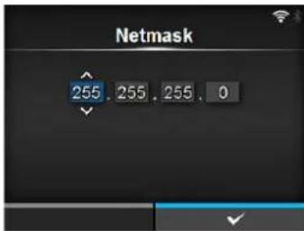
Gateway
Interface > Network > Settings > Wi-Fi > IPv4 > Gateway
If you have selected Static in the Mode menu, set the default gateway address.
The setting range is as follows:
000.000.000.000 to 255.255.255.255
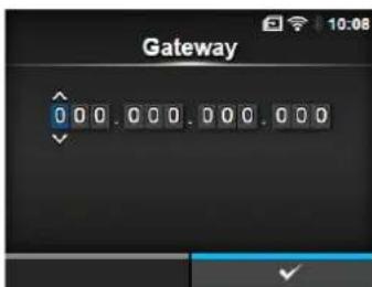
DNS
Interface > Network > Settings > Wi-Fi > IPv4 > DNS
If you have selected Static in the Mode menu, set and check DNS server addresses.
The setting range is as follows: 000.000.000.000 to 255.255.255.255
Note
You can register up to three IP addresses for the DNS server. Use a comma to delimit different IP addresses.
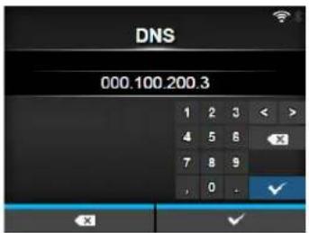
| IPv6 | |||
| Interface > Network > Settings > Wi-Fi > IPv6Configure IPv6 for Wi-Fi. The setting items are as follows: | 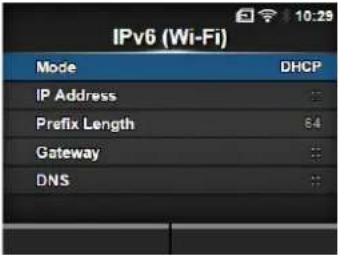 | ||
| 1 Mode Select the IP address assignment method. | |||
| 2 DHCP / Renew Lease | Update the lease time and get the IP address from the DHCP server again.*Shows only if you have selected DHCP in the Mode menu.*Does not show if LAN is the active interface. | ||
| 3 IP | Address Set and check the IP address.If you have selected DHCP in the Mode menu, the screen shows the IP address you received from the DHCP server.If you have selected Static in the Mode menu, select to set the IP address. | ||
| 4 Prefix Length Set and check the prefix. | |||
| 5 Gateway Set and check | the default gateway address.If you have selected DHCP in the Mode menu, the screen shows the gateway address you received from the DHCP server.If you have selected Static in the Mode menu, select to set the default gateway address. | ||
| 6 DNS Set and check the | address of the primary DNS server.If you have selected Static in the Mode menu, select to set the primary address of the DNS server. | ||
| CAUTIONAfter setting, press the right soft button to enable the new setting. Press the left soft button to cancel the new setting and return to the previous setting. | |||
| NoteWhen Wi-Fi Direct is active, this IPv6 screen is not shown. In addition, you cannot change IP Address, Prefix Length, Gateway and DNS if Mode is DHCP or Auto. | |||
Mode
Interface > Network > Settings > Wi-Fi > IPv6 > Mode
Select the IP address assignment method.
The options are as follows:
- Auto: Automatically generate the IP address and gateway (stateless mode).
- DHCP: Automatically retrieve the IP address and gateway from the DHCP server automatically (stateful mode).
- Static: Manually set the IP address, gateway and subnet mask.
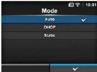
IP Address
Interface > Network > Settings > Wi-Fi > IPv6 > IP Address
If you have selected Static in the Mode menu, set the IP address.
The setting range is as follows:
0:0:0:0:0:0:0:1 to ffff:ffff:ffff:ffff:ffff:ffff:ffff
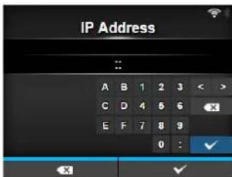
Prefix Length
Interface > Network > Settings > Wi-Fi > IPv6 > Prefix Length
If you have selected Static in the Mode menu, set the prefix.
The setting range is from 1 to 128.
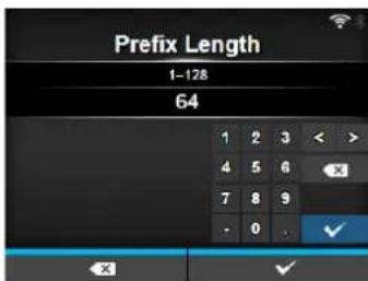
Gateway
Interface > Network > Settings > Wi-Fi > IPv6 > Gateway
If you have selected Static in the Mode menu, set the default gateway address.
The setting range is as follows:
0:0:0:0:0:0:0:0 to ffff:ffff:ffff:ffff:ffff:ffff:ffff
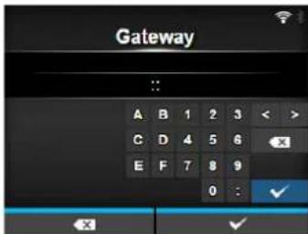
DNS
Interface > Network > Settings > Wi-Fi > IPv6 > DNS
If you have selected Static in the Mode menu, set the primary address of the DNS server.
The setting range is as follows: 0:0:0:0:0:0:0:0 to ffff:ffff:ffff:ffff:ffff:ffff:ffff
Note
You can register only one IP address for the DNS server for IPv6.
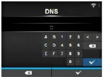
Proxy
Interface > Network > Settings > Wi-Fi > Proxy
Configure the proxy for Wi-Fi. The setting items are as follows:
1 Enabled Enable or disable use of proxy.
2 Server Set the proxy server address.
3 Exclude Exclude the proxy server usage.
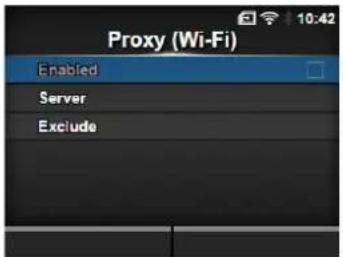
Enabled
Interface > Network > Settings > Wi-Fi > Proxy > Enabled
Enable or disable use of proxy.
The options are as follows:
- Enabled: Enable proxy server usage.
- Disabled: Disable proxy server usage.
Note
To enable the proxy, Server should be set and Exclude must contain at least 127.0.0.1 and localhost.
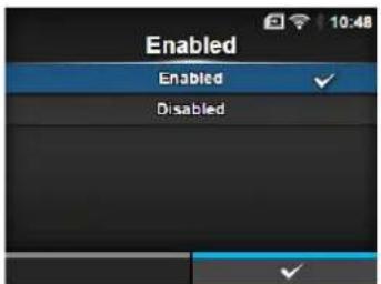
Server
Interface > Network > Settings > Wi-Fi > Proxy > Server
Set the name or IP address of the proxy server.
Note
Server should be set with a valid name or IP address and port number.
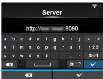
Exclude
Interface > Network > Settings > Wi-Fi > Proxy > Exclude
Set names, IP addresses or domains for the proxy to exclude.
Note
Exclude must contain at least 127.0.0.1 and localhost.
Wi-Fi Protected Setup
Interface > Network > Settings > Wi-Fi > Wi-Fi Protected Setup
Set the wireless LAN connection using the push button or PIN code method.
The setting items are as follows:
1 Button (PBC) Set the wireless LAN connection using the push button method.
2 PIN Set the wireless LAN connection using the PIN code method.
Note
- Refer to the manual of the access point device for its operation.
- This screen does not show if LAN or Wi-Fi Direct is active.
Button (PBC)
Interface > Network > Settings > Wi-Fi > Wi-Fi Protected Setup> Button (PBC)
Set the wireless LAN connection using the push button method.
-
Select Button (PBC) in the Wi-Fi Protected Setup menu and press the ← button.
-
When Scanning... shows on the screen, press the WPS button on the access point of the wireless LAN device.
-
When the connection to the access point is established, Successfully configured. shows on the screen.
PIN
Interface > Network > Settings > Wi-Fi > Wi-Fi Protected Setup > PIN
Set the wireless LAN connection using the PIN code method.
- Select PIN in the Wi-Fi Protected Setup menu and press the ← button.
- When Scanning... shows on the screen, set the PIN code shown on the screen to the access point of the wireless LAN or computer.
- When the connection to the access point is established, Successfully configured. shows on the screen.
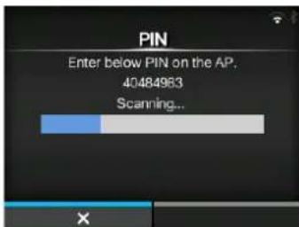
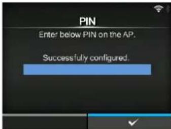
Wi-Fi Direct
Interface > Network > Settings > Wi-Fi > Wi-Fi Direct
Set the Wi-Fi Direct function.
*The Wi-Fi Direct function is enabled only if you have selected Infrastructure in the Mode menu.
The setting procedure is as follows:
- Set the device name for the printer using Device Name. You can enter 1 to 32 characters including alphabets (capital and small letters), numbers and symbols. Press the ➕ button to return to Wi-Fi menu and press the right soft button to enable changes.
- Select Connect to search and show the connectable device names or to accept connection requests when printer is GO (Group Owner).
Select the device name you want to connect using the ▲/▼ buttons, then press the right soft button.
- Select Start Group if you want to start a new persistent group or select a group from the list.
- Select Remove Group to remove the persistent group in step 3.
- Complete the connection according to the display on the printer or device you want to connect.
- Select Disconnect if you want to stop the connection.
Note
You can connect a maximum of ten devices.
When Wi-Fi Direct is active, Device Name cannot be changed.
Start Group and Remove Group show only if Wi-Fi is active and the printer is not connected to a Wi-Fi Direct network.
Disconnect shows if Wi-Fi is active and the printer is connected.
After setting up a start group, the printer will be set to GO (Group Owner) and will wait for a connection request from another device.
If the printer is powered off during a persistent group connection, the group will be started automatically after the printer is powered on.
Connect without group
Connect with group
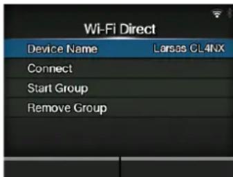
SSID
Interface > Network > Settings > Wi-Fi > SSID
Set the SSID.
The screen shows the Wi-Fi network detected by the printer.
Select the name of the Wi-Fi network you want to connect using the

buttons and press the right soft button to confirm.
To register a Wi-Fi network manually, press the left soft button and enter the name of the network.
You can enter a maximum of thirty-two characters including alphabet (upper case and lower case), numbers and symbols.
Note
SSID is editable if LAN or Wi-Fi Direct is active.
Hidden SSID
Interface > Network > Settings > Wi-Fi > Hidden SSID
Set the Hidden SSID (stealth function).
Shows if you have selected Infrastructure in the Mode menu.
The options are as follows:
- Enabled
- Disabled
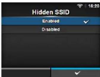
Mode
Interface > Network > Settings > Wi-Fi > Mode
Set the communication method of the wireless LAN.
The options are as follows:
- Infrastructure
- Ad-hoc
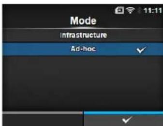
Channel
Interface > Network > Settings > Wi-Fi > Channel
Set the communication channel.
Channel can be set only if you have selected Ad-hoc in the Mode menu. The number of channels you can set varies depending on the region of the printer.
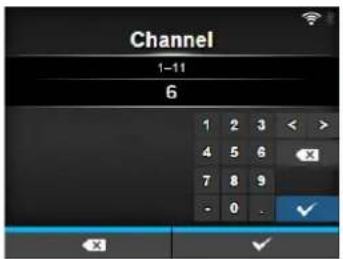
Security
Interface > Network > Settings > Wi-Fi > Security
Set the security method of the network. Set the security methods so that the printer, host and network devices match.
The options are as follows:
- None
• WEP
• WPA+WPA2
• W P A 2
• Dynamic WEP
If you have selected Ad-hoc in the Mode menu, only None and WEP will be available in the Security menu.
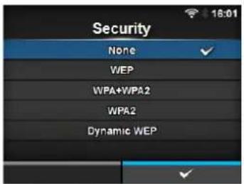
WEP Conf.
Interface > Network > Settings > Wi-Fi > WEP Conf.
Set the WEP key.
Shows only if you have selected WEP in the Security menu.
The setting items are as follows:
1 Authentication Set the WEP authentication method.
2 Key Index Set the key index.
3 Key #1 - Key #4 Set the WEP key1 - key4.
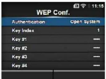
Authentication
Interface > Network > Settings > Wi-Fi > WEP Conf. > Authentication
Set the WEP authentication method.
The options are as follows:
- Open System
- Shared Key
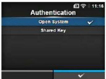
Key Index
Interface > Network > Settings > Wi-Fi > WEP Conf. > Key Index
Set the key index.
Set the key index (WEP key) according to the access point of the wireless LAN you connect.
The setting range is from 1 to 4.
CAUTION
Depending on the product, the range of the key index may be 0 to 3. In such a case, if you have set the printer to 1, then set the product to 0.
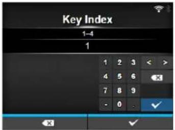
Key #1 - Key #4
Interface > Network > Settings > Wi-Fi > WEP Conf. > Key #1 - Key #4
Set the WEP key #1 - key #4.
You can enter alphabet (upper case and lower case) and numbers.
Depending on the length of the WEP key, the number of characters you can set is as follows:
- When the key length is 64 bit
ASCII: Five characters
Hexadecimal: Ten characters - When the key length is 128 bit
ASCII: Thirteen characters
Hexadecimal: Twenty-six characters
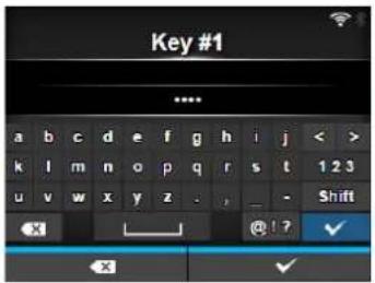
WPA Conf.
Interface > Network > Settings > Wi-Fi > WPA Conf.
Set the WPA authentication.
Shows only if you have selected WPA+WPA2 or WPA2 in the Security menu.
The setting items are as follows:
| 1 | W P A Authentication | Set the WPA authentication method. |
| 2 PSK Set the PSK shared key. |
*Shows only if you have selected Personal (PSK) in the WPA Authentication menu.
| 3 EAP Conf. Set the functions for EAP. |
*Shows only if you have selected items other than Personal (PSK) in the WPA Authentication menu.
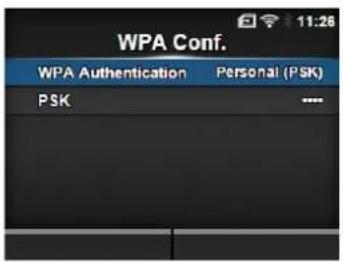
WPA Authentication
Interface > Network > Settings > Wi-Fi > WPA Conf. > WPA Authentication
Set the WPA authentication method.
The options are as follows:
- Personal (PSK)
- Enterprise (802.1x)
• CCKM
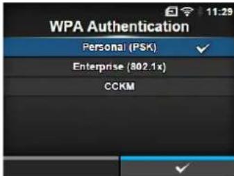
PSK
Interface > Network > Settings > Wi-Fi > WPA Conf. > PSK
Set the PSK shared key.
Shows only if you have selected Personal (PSK) in the WPA
Authentication menu.
You can enter alphabetic, numeric and symbolic characters in the range of 8-63 ASCII or 64 hexadecimal digits.
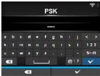
| EAP Conf. | ||
| Interface > Network > Settings > Wi-Fi > EAP Conf. | ||
| Interface > Network > Settings > Wi-Fi > WPA Conf. > EAP Conf. | ||
| Set the functions for EAP. Shows only if you have selected an item other than Personal (PSK) in the WPA Authentication menu or if you have selected Dynamic WEP in the Security menu. The setting items are as follows: | ||
| 1 EAP Mode Set the EAP | Mode (authentication mode). | |
| 2 Inner Method Set the inner method. | ||
| 3 Username Set the user name. | ||
| 4 Password Set the password. | ||
| 5 Anon. Outer ID Set the external ID. *Shows only if you have selected FAST, PEAP or TTLS in the EAP Mode menu. | ||
| 6Verify Server Cert. Enable or disable server authentication. *Shows only if you have selected anything other than LEAP in the EAP Mode menu. | ||
| 7 Private Key P/W Set the Private Key password. *Shows only if you have selected TLS in either the EAP Mode menu or Inner Method menu. | ||
| 8 PAC Auto Provisioning | Enable or disable PAC Auto Provisioning. *Shows only if you have selected FAST in the EAP Mode menu. | |
| 9 PAC P/W Set the PAC password. *Shows only if you have selected FAST in the EAP Mode menu and if you have selected Disabled in PAC Auto Provisioning. | ||
EAP Mode
Interface > Network > Settings > Wi-Fi > EAP Conf. > EAP Mode
Interface > Network > Settings > Wi-Fi > WPA Conf. > EAP Conf. > EAP Mode
Set the EAP Mode (authentication mode).
The options are as follows:
• F AST
- LEAP
- PEAP
• TLS
• TTLS
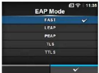
Inner Method
Interface > Network > Settings > Wi-Fi > EAP Conf. > Inner Method
Interface > Network > Settings > Wi-Fi > WPA Conf. > EAP Conf. > Inner Method
Set the inner method.
Shows only if you have selected FAST, PEAP or TTLS in the EAP Mode menu.
- If you have selected FAST in the EAP Mode menu, the options are MSCHAPv2, GTC and TLS.
- If you have selected PEAP in the EAP Mode menu, the options are MSCHAPv2, GTC, MD5, OTP and TLS.
- If you have selected TTLS in the EAP Mode menu, the options are MSCHAPv2, MSCHAP, CHAP, PAP, EAP-GTC, EAP-MD5, EAP-MSCHAPv2, EAP-OTP and EAP-TLS.
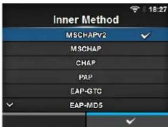
Username
Interface > Network > Settings > Wi-Fi > EAP Conf. > Username
Interface > Network > Settings > Wi-Fi > WPA Conf. > EAP Conf. > Username
Set the user name.
You can enter alphabetic, numeric and symbolic characters in the range of 0 to 63 characters.
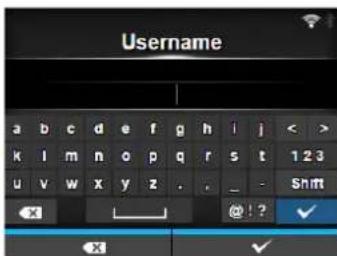
Password
Interface > Network > Settings > Wi-Fi > EAP Conf. > Password
Interface > Network > Settings > Wi-Fi > WPA Conf. > EAP Conf. > Password
Set the password.
You can enter alphabetic, numeric and symbolic characters in the range of 0 to 32 characters.
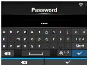
Anon. Outer ID
Interface > Network > Settings > Wi-Fi > EAP Conf. > Anon. Outer ID
Interface > Network > Settings > Wi-Fi > WPA Conf. > EAP Conf. > Anon. Outer ID
Set the external ID.
Shows only if you have selected FAST, PEAP or TTLS in the EAP Mode menu.
You can enter alphabetic, numeric and symbolic characters in the range of 0 to 63 characters.
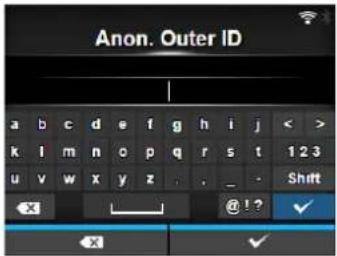
Verify Server Cert.
Interface > Network > Settings > Wi-Fi > EAP Conf. > Verify Server Cert.
Interface > Network > Settings > Wi-Fi > WPA Conf. > EAP Conf. > Verify Server Cert.
Enable or disable server certificate validation.
Shows only if you have selected anything other than LEAP in the EAP Mode menu.
The options are as follows:
- Enabled: Enable server certificate validation.
- Disabled: Disable server certificate validation.
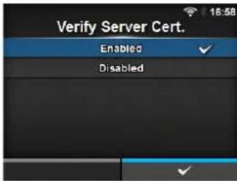
Private Key P/W
Interface > Network > Settings > Wi-Fi > EAP Conf. > Private Key P/W
Interface > Network > Settings > Wi-Fi > WPA Conf. > EAP Conf. > Private Key P/W
Set the Private Key password.
Shows only if you have selected TLS in either the EAP Mode menu or Inner Method menu.
You can enter alphabetic, numeric and symbolic characters in the range of 0 to 64 characters.
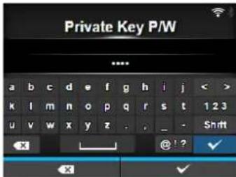
PAC Auto Provisioning
Interface > Network > Settings > Wi-Fi > EAP Conf. > PAC Auto Provisioning
Interface > Network > Settings > Wi-Fi > WPA Conf. > EAP Conf. > PAC Auto Provisioning
Enable or disable PAC Auto Provisioning.
Shows only if you have selected FAST in the EAP Mode menu.
The options are as follows:
- Enabled: Enable PAC Auto Provisioning.
- Disabled: Disable PAC Auto Provisioning.
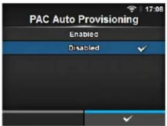
PAC P/W
Interface > Network > Settings > Wi-Fi > EAP Conf. > PAC P/W
Interface > Network > Settings > Wi-Fi > WPA Conf. > EAP Conf. > PAC P/W
Set the PAC password.
Shows only if you have selected FAST in the EAP Mode menu and if you have selected Disabled in the PAC Auto Provisioning.
You can enter alphabetic, numeric and symbolic characters in the range of 0 to 64 characters.
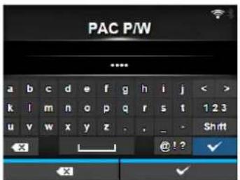
Interface
Interface > Network > Settings > Interface
Select the network interface.
This item is to select the network interface from LAN or wireless LAN when you have installed the optional wireless LAN.
The options are as follows:
- Auto: Automatically select between LAN and wireless LAN interface at printer startup. LAN is selected if LAN cable is connected to a link established hub (Link LED is flashing) at printer startup. Wireless LAN is selected if LAN is not detected at printer startup.
• LAN: Use LAN interface (or Force LAN interface). - Wi-Fi: Use wireless LAN interface (or Force wireless LAN interface).
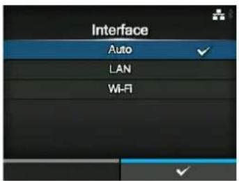
Note
The message prompting to restart the printer will appear on the online/offline screen if you have made any changes. In such a case, reboot the printer to make the setting effective.
| Services | |||
| Interface > Network > ServicesSet the TCP/IP port number, NTP, LPD, FTP or SNMP.The setting items are as follows: | 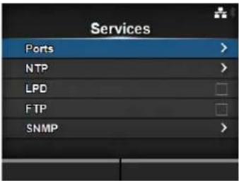 | ||
| 1 Ports Set the port number. | |||
| 2 NTP Set the functions for NTP. | |||
| 3 LPD Set the functions for LPD. | |||
| 4 FTP Set the functions for FTP. | |||
| 5 SNMP Set the functions for SNMP. | |||
| Ports | |||
| Interface > Network > Services > PortsThe setting items are as follows: | 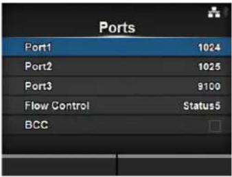 | ||
| 1 Port1 Set the port number. | |||
| 2 Port2 Set the port number. | |||
| 3 Port3 Set the port number. | |||
| 4 Flow Control Set the communication protocol. | |||
| 5 BCC Set the BCC check function.*Shows only if you have selected Status5 in the Flow Control menu. | |||
| Port1 | |
| Interface > Network > Services > Ports > Port1Set the port number.The setting range is from 1 to 65535.Each port (1, 2 and 3) must be set to different values. | 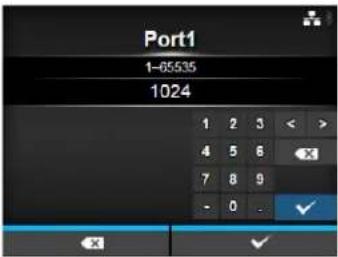 |
Port2
Interface > Network > Services > Ports > Port2
Set the port number.
The setting range is from 1 to 65535.
Each port (1, 2 and 3) must be set to different values.
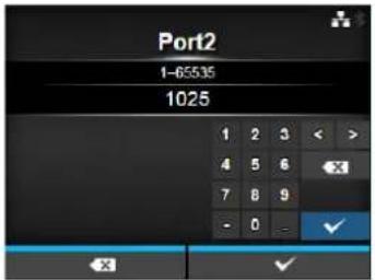
Port3
Interface > Network > Services > Ports > Port3
Set the port number.
The setting range is from 1 to 65535.
Each port (1, 2 and 3) must be set to different values.
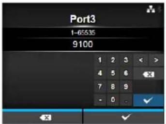
Flow Control
Interface > Network > Services > Ports > Flow Control
Set the communication protocol.
The options are as follows:
- Status 4
• Status 4 ENQ
- Status 3
- Status 5
- None
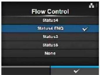
BCC
Interface > Network > Services > Ports > BCC
Enable or disable the BCC check function.
Shows only if you have selected Status5 in the Flow Control menu.
The options are as follows:
- Enabled: Enable the BCC check function.
- Disabled: Disable the BCC check function.

NTP
Interface > Network > Services > NTP
Set the functions for NTP.
The NTP function gets the time information from the NTP server through the network and sets the time of the printer.
The setting items are as follows:
1 Enable Enable or disable the functions for NTP.
2 Error Set to show the NTP error message if detected.
3 Time Server IP Set the IP address of the NTP server.
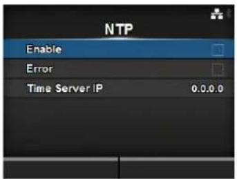
Enable
Interface > Network > Services > NTP > Enable
Enable or disable the functions for NTP.
The options are as follows:
- Enabled: Enable the NTP function.
- Disabled: Disable the NTP function.
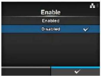
Error
Interface > Network > Services > NTP > Error
Set to show the NTP error message if detected.
The options are as follows:
- Enabled: Shows the error message.
- Disabled: Do not show the error message.
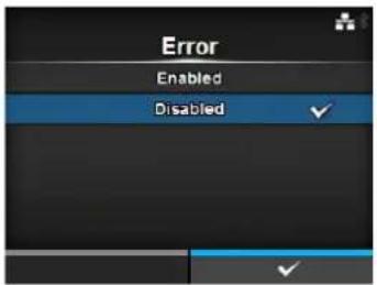
Time Server IP
Interface > Network > Services > NTP > Time Server IP
Set the IP address of the NTP server.
The setting range is from 0.0.0.0 to 255.255.255.255.
The IP address should normally be set to 0.0.0.0 (the default) which means that global NTP servers will be assigned automatically. Set to a valid IP if the time synchronization is requested for a specific server.
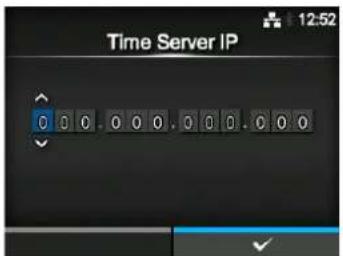
LPD
Interface > Network > Services > LPD
Enable or disable the functions for LPD.
The options are as follows:
- Enabled: Enable the LPD function.
• Disabled: Disable the LPD function.
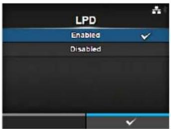
FTP
Interface > Network > Services > FTP
Set the functions for FTP.
The setting items are as follows:
1 Enable Enable or disable the functions for FTP.
2 FTP Timeout Set the connection timeout period between the
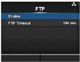
Enable
Interface > Network > Services > FTP > Enable
Enable or disable the functions for FTP.
The options are as follows:
- Enabled: Enable the FTP function.
- Disabled: Disable the FTP function.
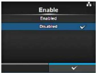
FTP Timeout
Interface > Network > Services > FTP > FTP Timeout
Set the connection timeout period between the printer's FTP server and clients.
Specify the maximum number of seconds that the printer's FTP server will allow clients to stay connected without receiving any data on either the control or data connection.
The setting range is from 10 to 3600 seconds.
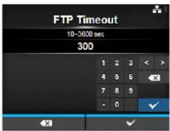
SNMP
Interface > Network > Services > SNMP
Set the functions for SNMP.
The SNMP function enables you to monitor and manage a UDP/IP based network.
The setting items are as follows:
1 sysContact Set the contact information.
2 sysName Set the name information.
3 sysLocation Set the location information.
4 Agent Set the Agent function.
5 Traps Set the Traps function.
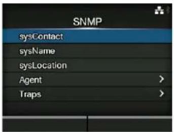
sysContact
Interface > Network > Services > SNMP > sysContact
Set the contact information.
You can enter alphabetic, numeric and symbolic characters in the range of 0 to 255 characters.
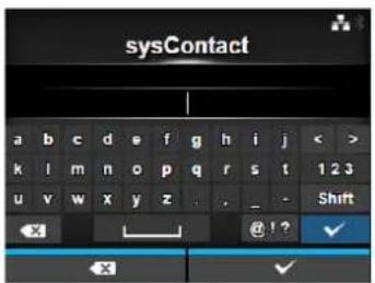
sysName
Interface > Network > Services > SNMP > sysName
Set the name information.
You can enter alphabetic, numeric and symbolic characters in the range of 0 to 255 characters.
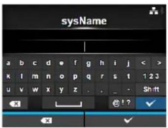
sysLocation
Interface > Network > Services > SNMP > sysLocation
Set the location information.
You can enter alphabetic, numeric and symbolic characters in the range of 0 to 255 characters.
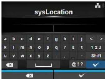
Agent
Interface > Network > Services > SNMP > Agent
Set the Agent function.
The setting items are as follows:
1 Enable Use the Agent function.
2 Read-Only Set the Read-Only function.
3 Read-Write Set the Read-Write function.
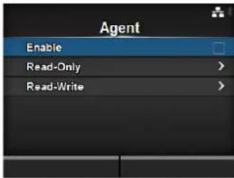
Enable
Interface > Network > Services > SNMP > Agent > Enable
Enable or disable the functions for Agent.
The options are as follows:
- Enabled: Enable the functions for Agent.
- Disabled: Disable the functions for Agent.
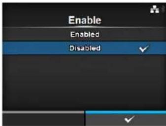
| Read-Only | |||
| Interface > Network > Services > SNMP > Agent > Read-OnlySet the Read-Only function.The setting items are as follows: | |||
| 1 SNMP Version Set the SNMP version. | |||
| 2 Community Set the Read-Only community name.*Shows only if you have selected 1|2c|3 or 1|2cin the SNMP Version menu. | |||
| 3 User Set the Read-Only user name.*Shows only if you have selected 1|2c|3 or 3 inthe SNMP Version menu. | |||
| 4 User Security Set the Read-Only security level.*Shows only if you have selected 1|2c|3 or 3 inthe SNMP Version menu. | |||
| 5 AuthenticationProtocol | Set the authentication protocol.*Shows only if you have selectedAuthentication or Privacy in the UserSecurity menu. | ||
| 6 AuthenticationPassphrase | Set the authentication passphrase.*Shows only if you have selectedAuthentication or Privacy in the UserSecurity menu. | ||
| 7 Privacy Protocol Set the privacy protocol.*Shows only if you have selected Privacy inthe User Security menu. | |||
| 8 PrivacyPassphrase | Set the privacy passphrase.*Shows only if you have selected Privacy inthe User Security menu. | ||
| SNMP Version | |
| Interface > Network > Services > SNMP > Agent > Read-Only > SNMP VersionSet the SNMP version.The options are as follows:1|2c|31|2c3Disabled | 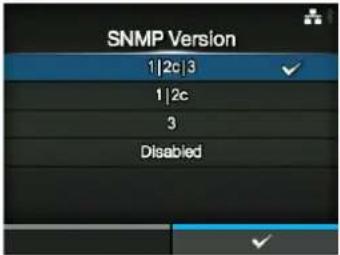 |
Community
Interface > Network > Services > SNMP > Agent > Read-Only > Community
Set the Read-Only community name.
Shows only if you have selected 1|2c|3 or 1|2c in the SNMP Version menu.
You can enter alphabetic, numeric and symbolic characters in the range of 1 to 32 characters.
Initial setting: public
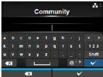
User
Interface > Network > Services > SNMP > Agent > Read-Only > User
Set the Read-Only user name.
Shows only if you have selected 1|2c|3 or 3 in the SNMP Version menu.
You can enter alphabetic, numeric and symbolic characters in the range of 1 to 32 characters.
Initial setting: rouser
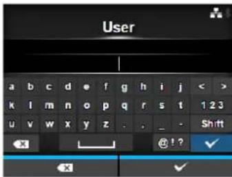
User Security
Interface > Network > Services > SNMP > Agent > Read-Only > User Security
Set the Read-Only security level.
Shows only if you have selected 1|2c|3 or 3 in the SNMP Version menu.
The options are as follows:
- None
- Authentication
- Privacy
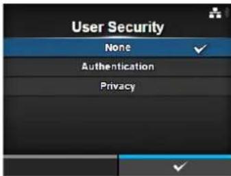
Authentication Protocol
Interface > Network > Services > SNMP > Agent > Read-Only > Authentication Protocol
Set the authentication protocol.
Shows only if you have selected Authentication or Privacy in the User Security menu.
The options are as follows:
- MD5
• SHA
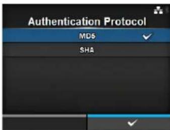
Authentication Passphrase
Interface > Network > Services > SNMP > Agent > Read-Only > Authentication Passphrase
Set the authentication passphrase.
Shows only if you have selected Authentication or Privacy in the User Security menu.
You can enter alphabetic, numeric and symbolic characters in the range of 8 to 32 characters.
Initial setting: mypassword
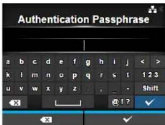
Privacy Protocol
Interface > Network > Services > SNMP > Agent > Read-Only > Privacy Protocol
Set the privacy protocol.
Shows only if you have selected Privacy in the User Security menu.
The options are as follows:
• DES
• AES
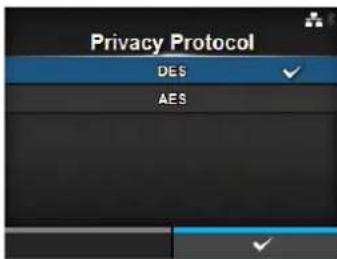
Privacy Passphrase
Interface > Network > Services > SNMP > Agent > Read-Only > Privacy Passphrase
Set the privacy passphrase.
Shows only if you have selected Privacy in the User Security menu.
You can enter alphabetic, numeric and symbolic characters in the range of 8 to 32 characters.
Initial setting: mypassword
| Read-Write | |||
| Interface > Network > Services > SNMP > Agent > Read-WriteSet the Read-Write function.The setting items are as follows: | |||
| 1 SNMP Version Set the SNMP version. | |||
| 2 Community Set the Read-write community name.*Shows only if you have selected 1|2c|3 or 1|2cin the SNMP Version menu. | |||
| 3 User Set the Read-Write user name.*Shows only if you have selected 1|2c|3 or 3 inthe SNMP Version menu. | |||
| 4 User Security Set the Read-write security level.*Shows only if you have selected 1|2c|3 or 3 inthe SNMP Version menu. | |||
| 5 AuthenticationProtocol | Set the authentication protocol.*Shows only if you have selectedAuthentication or Privacy in the UserSecurity menu. | ||
| 6 AuthenticationPassphrase | Set the authentication passphrase.*Shows only if you have selectedAuthentication or Privacy in the UserSecurity menu. | ||
| 7 Privacy Protocol Set the privacy protocol.*Shows only if you have selected Privacy inthe User Security menu. | |||
| 8 PrivacyPassphrase | Set the privacy passphrase.*Shows only if you have selected Privacy inthe User Security menu. | ||
| SNMP Version | |
| Interface > Network > Services > SNMP > Agent > Read-Write > SNMP VersionSet the SNMP version.The options are as follows:1|2c|31|2c3Disabled |  |
Community
Interface > Network > Services > SNMP > Agent > Read-Write > Community
Set the Read-Write community name.
Shows only if you have selected 1|2c|3 or 1|2c in the SNMP Version menu.
You can enter alphabetic, numeric and symbolic characters in the range of 0 to 32 characters.
Initial setting: private
User
Interface > Network > Services > SNMP > Agent > Read-Write > User
Set the Read-Write user name.
Shows only if you have selected 1|2c|3 or 3 in the SNMP Version menu.
You can enter alphabetic, numeric and symbolic characters in the range of 0 to 32 characters.
Initial setting: rwuser
User Security
Interface > Network > Services > SNMP > Agent > Read-Write > User Security
Set the Read-Write security level.
Shows only if you have selected 1|2c|3 or 3 in the SNMP Version menu.
The options are as follows:
- None
- Authentication
- Privacy
Authentication Protocol
Interface > Network > Services > SNMP > Agent > Read-Write > Authentication Protocol
Set the authentication protocol.
Shows only if you have selected Authentication or Privacy in the User Security menu.
The options are as follows:
• MD5
• SHA
Authentication Passphrase
Interface > Network > Services > SNMP > Agent > Read-Write > Authentication Passphrase
Set the authentication passphrase.
Shows only if you have selected Authentication or Privacy in the User Security menu.
You can enter alphabetic, numeric and symbolic characters in the range of 0 to 32 characters.
Initial setting: mypassword
Privacy Protocol
Interface > Network > Services > SNMP > Agent > Read-Write > Privacy Protocol
Set the privacy protocol.
Shows only if you have selected Privacy in the User Security menu.
The options are as follows:
• DES
• AES
Privacy Passphrase
Interface > Network > Services > SNMP > Agent > Read-Write > Privacy Passphrase
Set the privacy passphrase.
Shows only if you have selected Privacy in the User Security menu.
You can enter alphabetic, numeric and symbolic characters in the range of 8 to 32 characters.
Initial setting: mypassword
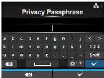
| Traps | |||
| Interface > Network > Services > SNMP > TrapsSet the Traps function.The setting items are as follows: | 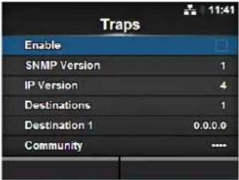 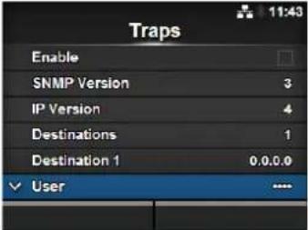 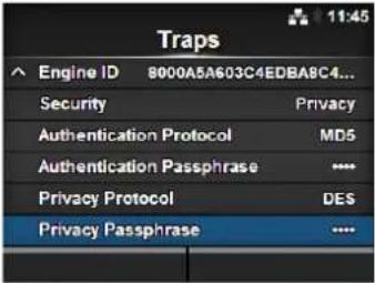 | ||
| 1 Enable Use the Traps function. | |||
| 2 SNMP Version Set the SNMP version. | |||
| 3 IP Version Set the IP version. | |||
| 4 Destinations Set the number of trap destinations. | |||
| 5 Destination 1 Set address 1 for the trap destination. | |||
| 6 Destination 2 Set address 2 for the trap destination.*Shows only if you have selected 2 or 3 in the Destination menu. | |||
| 7 Destination 3 Set address 3 for the trap destination.*Shows only if you have selected 3 in the Destination menu. | |||
| 8 Community Set the Traps community name.*Shows only if you have selected 1 or 2c in the SNMP Version menu. | |||
| 9 User Set the Traps user name.*Shows only if you have selected 3 in the SNMP Version menu. | |||
| 10 Engine ID Set the engine ID.*Shows only if you have selected 3 in the SNMP Version menu. | |||
| 11 Security Set the security level.*Shows only if you have selected 3 in the SNMP Version menu. | |||
| 12 Authentication Protocol | Set the authentication protocol.*Shows only if you have selected Authentication or Privacy in the Security menu. | ||
| 13 Authentication Passphrase | Set the authentication passphrase.*Shows only if you have selected Authentication or Privacy in the Security menu. | ||
| 14 Privacy Protocol | Set the privacy protocol.*Shows only if you have selected Privacy in the Security menu. | ||
| 15 Privacy Passphrase | Set the privacy passphrase.*Shows only if you have selected Privacy in the Security menu. | ||
Enable
Interface > Network > Services > SNMP > Traps > Enable
Enable or disable the functions for Traps.
The options are as follows:
- Enabled: Enable the Traps function.
- Disabled: Disable the Traps function.

SNMP Version
Interface > Network > Services > SNMP > Traps > SNMP Version
Set the SNMP version.
The options are as follows:
• 1
· 2c
· 3
IP Version
Interface > Network > Services > SNMP > Traps > IP Version
Set the IP version to use for trap destinations.
The options are as follows:
• 4 : Set the IP version to IPv4.
- 6 : Set the IP version to IPv6.
Destinations
Interface > Network > Services > SNMP > Traps > Destinations
Set the number of trap destinations.
The setting range is from 1 to 3.
Destination 1
Interface > Network > Services > SNMP > Traps > Destination 1
Set address 1 for trap destination.
The displayed IP version differs depending on the IP Version setting.
Destination 2
Interface > Network > Services > SNMP > Traps > Destination 2
Set address 2 for trap destination.
The displayed IP version differs depending on the IP Version setting.
Shows only if you have selected 2 or 3 in the Destination menu.
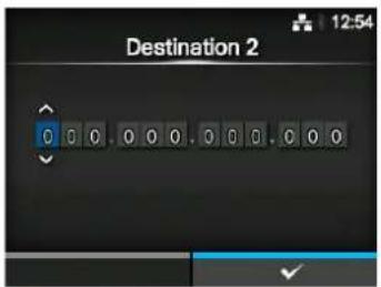
Destination 3
Interface > Network > Services > SNMP > Traps > Destination 3
Set address 3 for trap destination.
The displayed IP version differs depending on the IP Version setting.
Shows only if you have selected 3 in the Destination menu.
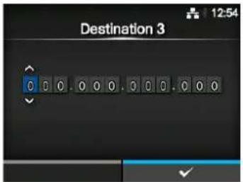
Community
Interface > Network > Services > SNMP > Traps > Community
Set the Traps community name.
Shows only if you have selected 1 or 2c in the SNMP Version menu.
You can enter alphabetic, numeric and symbolic characters in the range of 1 to 32 characters.
Initial setting: trapcom
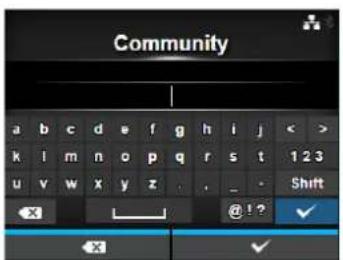
User
Interface > Network > Services > SNMP > Traps > User
Set the Traps user name.
Shows only if you have selected 3 in the SNMP Version menu.
You can enter alphabetic, numeric and symbolic characters in the range of 1 to 32 characters.
Initial setting: trapuser
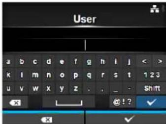
Engine ID
Interface > Network > Services > SNMP > Traps > Engine ID
Set the engine ID.
Shows only if you have selected 3 in the SNMP Version menu.
Initial setting: Created from the MAC address.
Hexadecimal characters are allowed and the range is from 10 to 64 characters (only an even number of characters are allowed).
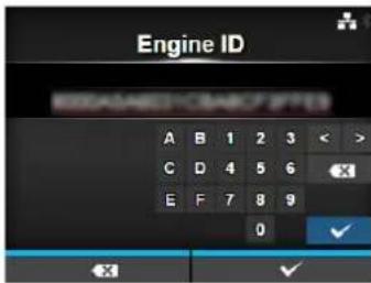
Security
Interface > Network > Services > SNMP > Traps > Security
Set the security level.
Shows only if you have selected 3 in the SNMP Version menu.
The options are as follows:
- None
- Authentication
- Privacy
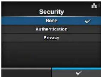
Authentication Protocol
Interface > Network > Services > SNMP > Traps > Authentication Protocol
Set the authentication protocol.
Shows only if you have selected Authentication or Privacy in the
Security menu.
The options are as follows:
• MD5
• SHA
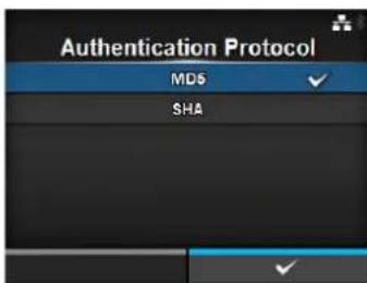
Authentication Passphrase
Interface > Network > Services > SNMP > Traps >
Authentication Passphrase
Set the authentication passphrase.
Shows only if you have selected Authentication or Privacy in the Security menu.
You can enter alphabetic, numeric and symbolic characters in the range of 0 to 32 characters.
Initial setting: mypassword
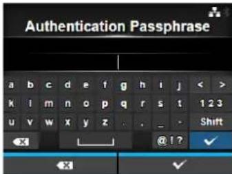
Privacy Protocol
Interface > Network > Services > SNMP > Traps > Privacy Protocol
Set the privacy protocol.
Shows only if you have selected Privacy in the Security menu.
The options are as follows:
• DES
• AES
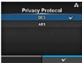
Privacy Passphrase
Interface > Network > Services > SNMP > Traps > Privacy Passphrase
Set the privacy passphrase.
Shows only if you have selected Privacy in the Security menu.
You can enter alphabetic, numeric and symbolic characters in the range of 8 to 32 characters.
Initial setting: mypassword
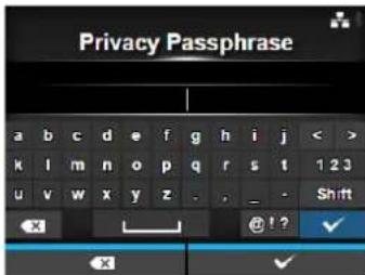
| Advanced | |||
| Interface > Network > AdvancedSet the advanced function for the interface.The setting item is as follows: | 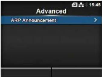 | ||
| 1 | A R PAnnouncement | Set the ARP announcement. | |
| ARP Announcement | |||
| Interface > Network > Advanced > ARP AnnouncementSet the functions for ARP announcement.The ARP announcement is useful for updating other hosts mapping of a hardware address when the IP address or MAC address of the sender has changed.The setting items are as follows: | 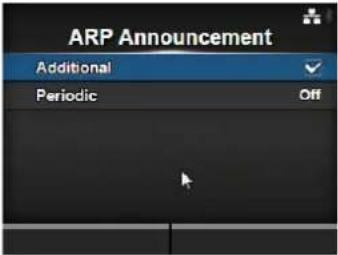 | ||
| 1 Additional Enable or dis | able the additional ARP announcement. | ||
| 2 Periodic Set the periodic timing for ARP announcement. | |||
| Additional | |
| Interface > Network > Advanced > ARP Announcement > AdditionalSet the additional ARP announcement.The options are as follows:Enabled: Enable the additional ARP announcement. The ARP is sent at 1, 2, 4, 8 and 16 seconds after the link up/DHCP assignment.Disabled: Disable the additional ARP announcement. The ARP is only sent at 1 second after the link up/DHCP assignment. | 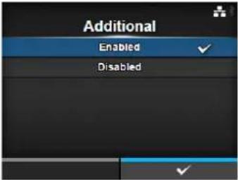 |
| Periodic | |
| Interface > Network > Advanced > ARP Announcement > PeriodicSet the interval of the ARP announcement in the range of 0 to 600 seconds.Initial setting: 0 | 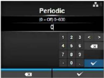 |
| IEEE1284 | |||
| Interface > IEEE1284Set the IEEE1284 connection.Shows only if the combo interface board is installed.The setting items are as follows: | 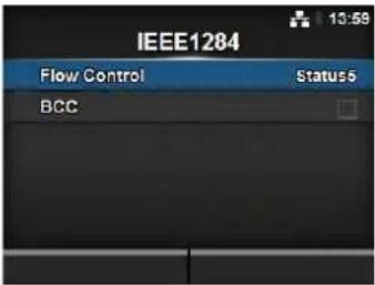 | ||
| 1 Flow Control Set the communication protocol. | |||
| 2 BCC Set the BCC check function.*Shows only if you have selected Status5 in the Flow Control menu. | |||
| Flow Control | |
| Interface > IEEE1284 > Flow ControlSet the communication protocol.The options are as follows:Status4 MultiStatus 5None | 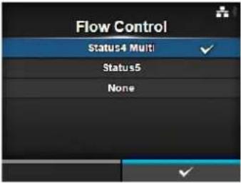 |
| BCC | |
| Interface > IEEE1284 > BCCEnable or disable the BCC check function.Shows only if you have selected Status5 in the Flow Control menu.The options are as follows:Enabled: Enable the BCC check function.Disabled: Disable the BCC check function. | 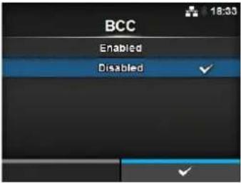 |
| RS-232C | |||
| Interface > RS-232CSet the RS-232C connection.Shows only if the combo interface board is installed.The setting items are as follows: | 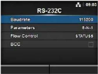 | ||
| 1 Ba | udrate Set the comm | unication speed. | |
| 2 Parameters Set the data parameters. | |||
| 3 Flow Control Set the com | mmunication protocol. | ||
| 4 BCC Set the BCC check function.*Shows only if you have selected STATUS5 in the Flow Control menu. | |||
| Baudrate | |
| Interface > RS-232C > BaudrateSet the baud rate (bps).The options are as follows:• 2 4 0 0• 4 8 0 0• 9 6 0 0• 19200• 38400• 57600• 115200 | 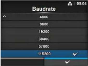 |
Parameters
Interface > RS-232C > Parameters
Set the data parameter.
The options are as follows:
Refer to the table below for the parameter configurations.
· 8 - N - 1
• 8-0-1
· 8 - E - 1
• 8 - N - 2
• 8-0-2
• 8 - E - 2
• 7 - N - 1
• 7-0-1
• 7 - E - 1
• 7 - N - 2
• 7-0-2
• 7 - E - 2
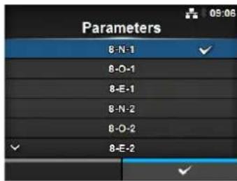
Parameter Configurations List
| Parameter Data length (bit) Parity Stop bit (bit) | |||
| 8-N-1 8 | N | O | N |
| 8-O-1 8 | O | D | D |
| 8-E-1 8 EVEN 1 | |||
| 8-N-2 8 | N | O | N |
| 8-O-2 8 | O | D | D |
| 8-E-2 8 EVEN 2 | |||
| 7-N-1 7 | N | O | N |
| 7-O-1 7 | O | D | D |
| 7-E-1 7 EVEN 1 | |||
| 7-N-2 7 | N | O | N |
| 7-O-2 7 | O | D | D |
| 7-E-2 7 EVEN 2 | |||
Flow Control
Interface > RS-232C > Flow Control
Set the communication protocol.
The options are as follows:
- READY/BUSY Multi
• XON/XOFF Multi - STATUS 3
- STATUS 4
- STATUS 5
- None
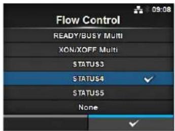
BCC
Interface > RS-232C > BCC
Enable or disable the BCC check function.
Shows only if you have selected STATUS5 in the Flow Control menu.
The options are as follows:
- Enabled: Enable the BCC check function.
- Disabled: Disable the BCC check function.
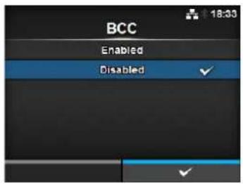
USB
Interface > USB
Set the USB connection.
The setting items are as follows:
1 Flow Control Set the communication protocol.
2 BCC Set the BCC check function.
*Shows only if you have selected Status5 in the Flow Control menu.
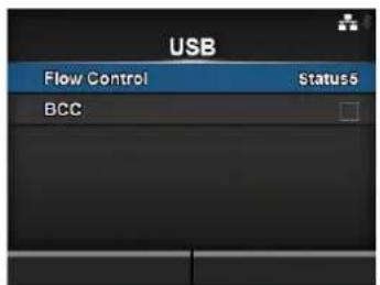
Flow Control
Interface > USB > Flow Control
Set the communication protocol.
The options are as follows:
- Status 4
- Status 5
- None
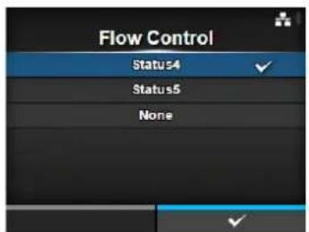
BCC
Interface > USB > BCC
Enable or disable the BCC check function.
Shows only if you have selected Status5 in the Flow Control menu.
The options are as follows:
- Enabled: Enable the BCC check function.
- Disabled: Disable the BCC check function.
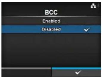
Bluetooth
Interface > Bluetooth
Set the Bluetooth connection.
The setting items are as follows:
1 Enable Enable or disable the functions for Bluetooth.
2 Name Set the device name for the printer.
3 Pin Code Set the PIN code.
4 BD Address Shows the BD address of this printer.
(You cannot change this address.)
5 Firm Version Shows the firmware version of the Bluetooth.
(You cannot change this value.)
6 Host BD Addr Check the Host BD address.
7 Authentication Set the authentication level.
8 ISI Set the ISI communication parameter.
9 ISW Set the ISW communication parameter.
10 PSI Set the PSI communication parameter.
11 | PSW | Set the PSW communication parameter.
12 CRC Mode Set the CRC check function.
13 Flow Control Set the communication protocol.
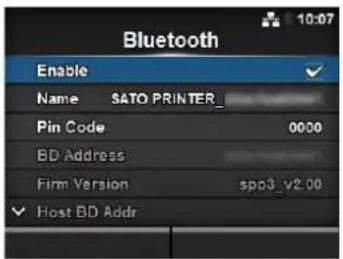
Enable
Interface > Bluetooth > Enable
Enable or disable the functions for Bluetooth.
The options are as follows:
- Enabled: Enable the Bluetooth function.
- Disabled: Disable the Bluetooth function.
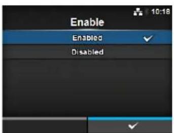
Name
Interface > Bluetooth > Name
Set the device name for the printer.
You can enter one to fifty-three characters including alphabet (upper case and lower case), numbers and symbols.
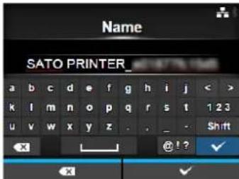
Pin Code
Interface > Bluetooth > Pin Code
Set the PIN code.
You can enter four to sixteen characters including alphabet (upper case and lower case), numbers and symbols.
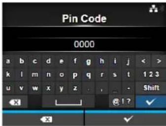
Authentication
Interface > Bluetooth > Authentication
Set the authentication level.
The options are as follows:
• None: No authentication
- Level 2-1: PIN code authentication, service level, no encryption
- Level 2-2: PIN code authentication, service level, encryption
- Level 3: PIN code authentication, link level, no encryption
- Level 4: Secure Simple Pairing compatible, service level, encryption (Can be communicated with devices that are not compatible with Secure Simple Pairing)
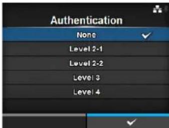
ISI
Interface > Bluetooth > ISI
Set the ISI communication parameter.
The setting range is 0, or from 18 to 4096.
Set to a value that is higher than the ISW communication parameter setting value.
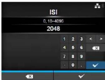
ISW
Interface > Bluetooth > ISW
Set the ISW communication parameter.
The setting range is 0, or from 17 to 4096.
The setting range varies depending on the ISI communication parameter setting value.
Set to a value that is lower than the ISI communication parameter setting value.
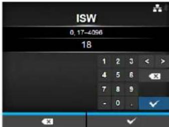
PSI
Interface > Bluetooth > PSI
Set the PSI communication parameter.
The setting range is from 18 to 4096.
Set to a value that is higher than the PSW communication parameter setting value.
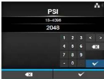
PSW
Interface > Bluetooth > PSW
Set the PSW communication parameter.
The setting range is from 17 to 4096.
The setting range varies depending on the PSI communication parameter setting value.
Set to a value that is lower than the PSI communication parameter setting value.
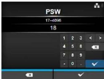
CRC Mode
Interface > Bluetooth > CRC Mode
Enable or disable the CRC check function.
The options are as follows:
- Enabled: Enable the CRC check function.
- Disabled: Disable the CRC check function.

Flow Control
Interface > Bluetooth > Flow Control
Set the communication protocol.
The options are as follows:
- Status 3
- Status4 Multi
- None
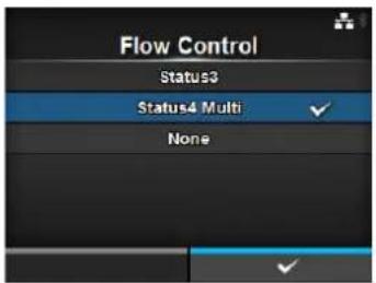
Ignore CR/LF
Interface > Ignore CR/LF
Ignore or acknowledge the CR/LF code of the received data.
The options are as follows:
- Enabled: Ignore the CR/LF code.
- Disabled: Do not ignore the CR/LF code.
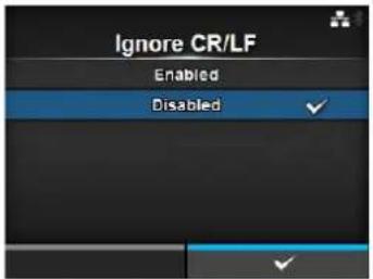
Ignore CAN/DLE
Interface > Ignore CAN/DLE
Ignore or acknowledge the CAN/DLE code of the received data.
The options are as follows:
- Enabled: Ignore the CAN/DLE code.
- Disabled: Do not ignore the CAN/DLE code.
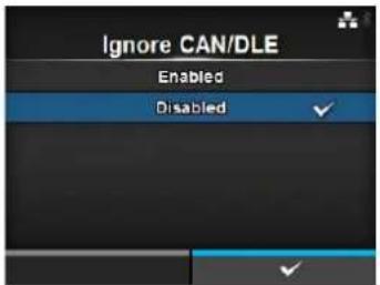
| External I/O | |||
| Interface > External I/OUse the external (EXT) terminal as an interface between the external device and the printer.Shows only if the combo interface board is installed.The setting items are as follows: | 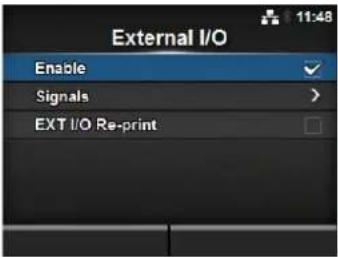 | ||
| 1 Enable Enable or disable the external signal interface. | |||
| 2 Signals Set the externa | signal.*Shows only if you have selected Enabled in the Enable menu. | ||
| 3 EXT I/O Re-print Set the | reprint function that uses the external terminal. | ||
| Enable | |
| Interface > External I/O > EnableEnable or disable the external signal interface.The options are as follows:Enabled: Enable the external signal interface.Disabled: Disable the external signal interface. | 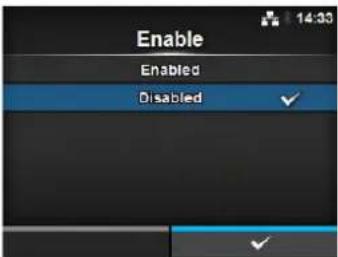 |
| Signals | |||
| Interface > External I/O > SignalsSet the external signal.Shows only if you have selectedEnabledin theEnablemenu.The setting items are as follows: | 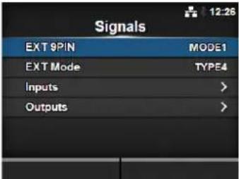 | ||
| 1 EXT 9PIN Set the function of the EXT 9PIN output. | |||
| 2 EXT Mode Set the mode of the Print End Signal. | |||
| 3 Inputs Set the input pin No. of the Signal Print Start/Signal Reprint. | |||
| 4 Outputs Set the output pin No. of the signals. | |||
EXT 9PIN
Interface > External I/O > Signals > EXT 9PIN
Set the function of the EXT 9PIN output.
The options are as follows:
- MODE1: The output signal becomes "Active" when there is remaining print data without error in online mode.
- MODE2: The output signal becomes "Active" when the printer is ONLINE.
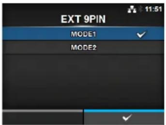
EXT Mode
Interface > External I/O > Signals > EXT Mode
Set the mode of the Print End Signal.
The options are as follows:
| Type Operation Details | |
| TYPE1 The | print end signal (PREND) is High before label printing, and it becomes Low after print completion. The signal level becomes High after 20 ms. |
| TYPE2 The | print end signal (PREND) is Low before label printing, and it becomes High after print completion. The signal level becomes Low after 20 ms. |
| TYPE3 The | print end signal (PREND) is High before label printing, becomes Low from the start to the end of print, and becomes High again after print completion. |
| TYPE4 The | print end signal (PREND) is Low before label printing, becomes High from the start to the end of print, and becomes Low again after print completion. |
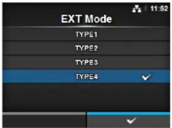
*Refer to Section 7.7.6 External Signal Interface (EXT) for the Timing Chart of the EXT Output Signal.
| Inputs | |||
| Interface > External I/O > Signals > InputsSet the input pin No. of the Signal Print Start/Signal Reprint.Press the ▲/▼ buttons to highlight the item that you want to change, then press the ◀/► buttons to change the pin No.Press the ← button to save the settings and return to theSignals menu.The setting items are as follows: | 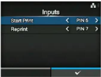 | ||
| 1 Start Print Set the input | pin No. of the Signal Print Start.The options are as follows:PIN5: Set the Signal Print Start to 5PIN.PIN7: Set the Signal Print Start to 7PIN. | ||
| 2 Reprint Set the input pin | No. of the Signal Reprint.The options are as follows:PIN5: Set the Signal Reprint to 5PIN.PIN7: Set the Signal Reprint to 7PIN. | ||
| NoteYou cannot set any inputs using the same pin number. If you attempt to set the same number, the settings will show in red and you cannot save the settings. | |||
| Outputs | |||
| Interface > External I/O > Signals > OutputsSet the output pin No. of the signals.Press the ▲/▼ buttons to highlight the item that you want to change, then press the ◀/► buttons to change the pin No.Press the ← button to save the settings and return to theSignals menu.The setting items are as follows: | 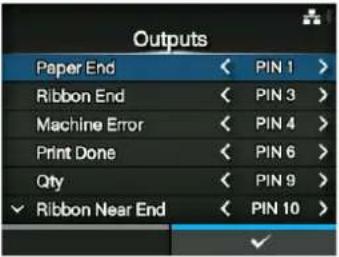 (If RFID Mode is enabled)(CL4NX only) (If RFID Mode is enabled)(CL4NX only) | ||
| 1 | Paper End/Paper/Ribbon End (If RFID Mode is enabled) (CL4NX only) | Set the output pin No. of the Signal Paper End.Set the output pin No. of the Signal Paper/Ribbon End if you have installed the RFID. | |
| 2 | Ribbon End/RFID Tag Error (If RFID Mode is enabled) (CL4NX only) | Set the output pin No. of the Signal Ribbon End.Set the output pin No. of the Signal RFID Tag Error if you have installed the RFID. | |
| 3 | Machine Error/Machine/RFID Error (If RFID Mode is enabled) (CL4NX only) | Set the output pin No. of the Signal Machine Error.Set the output pin No. of the Signal Machine/RFID Error if you have installed the RFID. | |
| 4 | Print Done | Set the output pin No. of the Signal Print End. | |
| 5 | Qty/Offline • MODE1: The | output signal becomes“Active” when there is remaining print data without error in online mode.MODE2: The output signal becomes “Active” when the printer is Online. | |
| 6 | Ribbon Near End | Set the output pin No. of the Signal Ribbon Near End. | |
| 7 | Dispenser Set the output | pin No. of the Signal Dispenser.*To use this signal, connect the dispenser unit or linerless kit (CL4NX only). | |
| 8 | Label Near End | Set the output pin No. of the Signal Label Near End.*This printer does not support the Label Near End function. Keep the setting off. | |
| The options for each signal outputs are as follows:• PIN1: Set the selected signal to 1PIN.• PIN3: Set the selected signal to 3PIN.• PIN4: Set the selected signal to 4PIN.• PIN6: Set the selected signal to 6PIN.• PIN9: Set the selected signal to 9PIN.• PIN10: Set the selected signal to 10PIN.• OFF: Set the selected signal to off mode. | |||
| NoteYou cannot set any outputs using the same pin number. If you attempt to set the same number, the settings will show in red and you cannot save the settings. | |||
EXT I/O Re-print
Interface > External I/O > EXT I/O Re-print
Set the reprint function for use with the external terminal.
The options are as follows:
- Enabled: Enable the reprint function.
- Disabled: Disable the reprint function.
| RFID (CL4NX only) | |||
| Interface > RFIDPerform the RFID settings.*Shows only for the RFID model.The setting items are as follows: |  | ||
| 1 Antenna Pitch Set the antenna pitch. | |||
| 2 Write Power Set radio power level used to write information to RFID tag. | |||
| 3 Read Power Set radio power level used to read information from RFID tag. | |||
| 4 Tag Offset Set distance to print on label BEFORE pausing to encode RFID. | |||
| 5 Reader Model Shows the RFID module model. | |||
| 6 Reader Version Shows the RFID module firmware version. | |||
| 7 View Shows the RFID tag data. | |||
| 8 Retry Mode Set whether to retry encoding of failed data after error recovery. | |||
| 9 Retries Set the number of failed encoding attempts before error warning/print pause. | |||
| 10 Mark bad tags Set the error print for the RFID tag error. | |||
| 11 MCS Set the Multi vendor or Chip-based Serialization. | |||
| 12 Non-RFID Warning | Set the non-RFID warning message. | ||
| 13 Log RFID Data Set the log function to record the encoded tag information. | |||
| 14 Data To Record Set the data to be recorded. | |||
| 15 Output Error Mode | Set the signal type for RFID errors. | ||
| 16 Pulse Length Set the length of an RFID error pulse. | |||
| 17 Counters Shows the RFID counter. | |||
Antenna Pitch

Interface > RFID > Antenna Pitch
Set the antenna pitch according to the Inlay Configuration Guide.
For details, access the following URL:
http://www.satoworldwide.com/rfid/
The options are as follows:
- Standard
- Short
*Shows only if the module is UHF.
Write Power

Interface > RFID > Write Power
Set radio power level used to write information to RFID tag according to the Inlay Configuration Guide. For details, access the following URL:
http://www.satoworldwide.com/rfid/
The setting range is from 0 to 24 dBm.
*Shows only if the module is UHF.
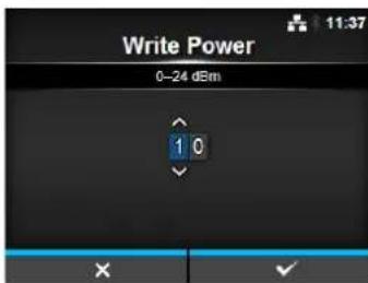
Read Power

Interface > RFID > Read Power
Set radio power level used to read information from RFID tag according to the Inlay Configuration Guide. For details, access the following URL:
http://www.satoworldwide.com/rfid/
The setting range is from 0 to 24 dBm.
*Shows only if the module is UHF.
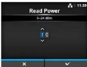
Tag Offset

Interface > RFID > Tag Offset
Set distance to print on label BEFORE pausing to encode RFID according to the Inlay Configuration Guide. This setting will be used when labels are not compatible with the CL4NX's antenna positions. For details, access the following URL:
http://www.satoworldwide.com/rfid/
The setting range is from 0 to 240 mm.
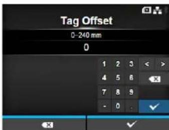
| View | |
| Interface > RFID > ViewShows the data of the RFID tag.Press the ← button to change to the Memory Bank screen.Press the right soft button (READ) to change to the Data Reading screen, to read and show the data.On the Data Reading screen, you can press the right soft button to feed the media and attempt to read the tag currently set in the printer. | 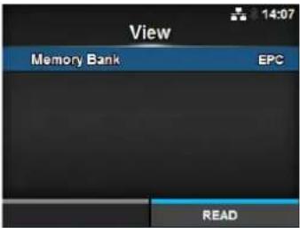 |
| Memory Bank | |
| Interface > RFID > View > Memory BankSet the memory area of the RFID tag to read.The readable memory areas are as follows:If the installed module is UHF• EPC: EPC area• T I D : TID area• USER: USER area• P C : PC/AFI areaIf the installed module is HF• USER: USER area• U I D : UID area | 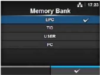 |
| Retry Mode | |
| Interface > RFID > Retry ModeSet whether to retry encoding of failed data after error recovery.The options are as follows:Retry:The printer will continue to attempt encoding the same data.However, if you have set the Retries to 0, the RFID error screen shows and printing continues.Release: Deletes the current print job, allowing the printer to move on to the next print job. If the RFID error occurs continuously and reaches the maximum number of Retries, printing stops. | 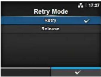 |
| Retries | |
| Interface > RFID > RetriesSet the number of failed encoding attempts before error warning/print pause.The setting range is from 0 to 9.If you set to 0, the RFID error screen shows and printing continues. | 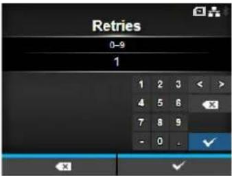 |
| Mark bad tags | UHF HF | |
| Interface > RFID > Mark bad tagsSet the error print for the RFID tag error.Enabled: Enable the RFID error print function.Disabled: Disable the RFID error print function.For details on the RFID error print, refer to Section 7.5.1 Printing RFID Tag Errors. | 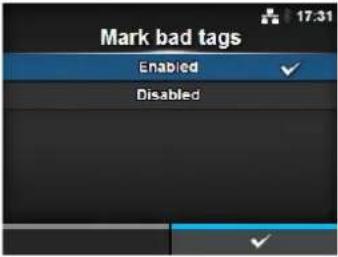 | |
| MCS | |||
| Interface > RFID > MCSSet the Multi vendor Chip-based Serialization. Shows only if the module is UHF. The setting items are as follows: | |||
| 1 MCS Enable or disable | the Multi vendor Chip-based Serialization. | ||
| 2 C h i pManufacturer | Manually set MCS manufacturer prefix.*Shows only if you have selectedEnabledin the MCS menu. | ||
| 3 Pre-Encoded Tag Enable | or disable for tags with pre-encoded EPC serial numbers.*Shows only if you have selectedEnabledin the MCS menu. | ||
| 4 Assign Prefix Set how to | assign the three digit prefix data.*Shows only if you have selectedEnabledin the MCS menu. | ||
| 5 MCS Prefix Digit Set the | length of manually assigned MCS manufacturer prefix.*Shows only if you have selectedManualin the Assign Prefix menu. | ||
| 6 Input Prefix Set the contents of MCS prefix.*Shows only if you have selectedManualin the Assign Prefix menu. | |||
| MCS | UHF | |
| Interface > RFID > MCS > MCSEnable or disable the Multi vendor Chip-based Serialization.Enabled: Enable the Multi vendor Chip-based Serialization.Disabled: Disable the Multi vendor Chip-based Serialization. |  | |
| NoteMulti vendor Chip-based Serialization: use TID as base for SGTIN serial number. | ||
| Chip Manufacturer | UHF | |
| Interface > RFID > MCS > Chip ManufacturerManually set MCS manufacturer prefix.Shows only if you have selectedEnabledin the MCSmenu.The options are as follows:· I M P I N J· A L I E N· NXP |  | |
| Pre-Encoded Tag | UHF | |
| Interface > RFID > MCS > Pre-Encoded TagEnable or disable for tags with pre-encoded EPC serial numbers. EPC GTIN data is still required.Shows only if you have selectedEnabledin the MCSmenu.The options are as follows:Enabled: Enable the pre-encoded tag Cooperative: Disable the pre-encoded tag. |  | |
| Assign Prefix | |
| Interface > RFID > MCS > Assign PrefixSet how to assign the three digit prefix data.Shows only if you have selectedEnabledin the MCSmenu.The options are as follows:Auto: Set to the manufacturer prefix selected in Chip Manufacturer.Manual: Set to the prefix determined by the MCS Prefix Digit and Input Prefix. |  |
| NoteDoes not show if Chip Manufacturer is NXP and Pre-Encoded Tag is enabled. | |
MCS Prefix Digit

Interface > RFID > MCS > MCS Prefix Digit
Set the length of manually assigned MCS manufacturer prefix.
This screen shows only if you have selected Manual in the Assign Prefix menu.
The options are as follows:
- None: Set the number of digits of the prefix data to 0.
Fill in 0 for all three 3 digits of the prefix data. - 1 bit : Set the number of digits of the prefix data to 1 digit. Fill in 0 for the lower 2 bits of the prefix data.
- 2 bits: Set the number of digits of the prefix data to 2 digits. Fill in 0 for the lower 1 bit of the prefix data.
• 3 bits: Set the number of digits of the prefix data to 3 digits.
Note
Does not show if Chip Manufacturer is NXP and Pre-Encoded Tag is enabled.
Input Prefix

Interface > RFID > MCS > Input Prefix
Set the contents of MCS prefix.
This screen shows only if you have selected Manual in the Assign Prefix menu.
The setting range is from 0 to 7.
Note
- Does not show if Chip Manufacturer is NXP and Pre-Encoded Tag is enabled.
- The setting range varies depending on the setting value in MCS Prefix Digit.
| Non-RFID Warning | |
| Interface > RFID > Non-RFID Warning Set the warning for non-RFID error. The options are as follows: • Enabled: Show the non-RFID warning upon error. • Disabled: Ignore the non-RFID error. | 16:28 Enabled Disabled ✓ |
| With Non-RFID warning enabled and RFID tag loaded, if the items received do not contain an RFID issue command, a warning error shows before printing so that the RFID tag will not be wasted. Press the CANCEL button to clear the warning message. | 14:00
Non-RFID Warning
1073RFID command does not exist. Disable warning or check command or label. QTY : 5 CANCEL ✗ |
| Log RFID Data | |
| Interface > RFID > Log RFID Data Set the log function to record the encoded tag information. The log data can record up to 100 tags of information. The options are as follows: • Enabled: Enable the log function to record the RFID data. • Disabled: Disable the log function to record the RFID data. | |
| Note UID data is recorded if the module is HF. |
| Data To Record | |
| Interface > RFID > Data To Record Set the data to record the log when Log RFID Data is enabled. The options are as follows: • EPC and TID: Store the EPC and TID data. • EPC: Store the EPC data. • T I D : Store the TID data. * Shows only if the module is UHF. | 19:04 Data To Record EPC and TID EPC TID |
| ✓ | |
| Output Error Mode | |
| Interface > RFID > Output Error ModeSet the signal type for RFID errors.The options are as follows:• Pulse: Outputs a pulse as the output signal when an RFID error occurs.• Level: Outputs a level as the output signal when an RFID error occurs. | [UHF HF] |
| Pulse Length | UHF HF |
| Interface > RFID > Pulse LengthSet the length of an RFID error pulse.Shows only if you have selected Pulse in the Output Error Mode menu.The options are as follows:1 0 0 m s2 0 0 m s3 0 0 m s4 0 0 m s5 0 0 m s |  |
| Counters | UHF HF | ||
| Interface > RFID> CountersShows the RFID counter.The display items are as follows: |  | ||
| 1 Lifetime Shows the number | ber of encoding successes, failures, and total attempts. | ||
| 2 User Shows the number | of encoding successes, failures, and total attempts after the RFID counter is cleared. | ||
| Lifetime | UHF HF | ||
| Interface > RFID> Counters > LifetimeShows the number of encoding successes, failures, and total attempts.The display items are as follows: | 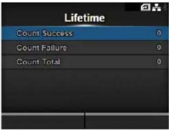 | ||
| 1 Count Success Shows the total number of successful times you have written to an RFID tag. | |||
| 2 Count Failure Shows the total number of RFID write errors. | |||
| 3 Count Total Shows the total number of times you have written to an RFID tag.This is the total number including Count Success and Count Failure. | |||
| User | UHF HF | ||
| Interface > RFID> Counters > UserShows the number of encoding successes, failures, and total attempts after the RFID counter is cleared.The display items are as follows: | 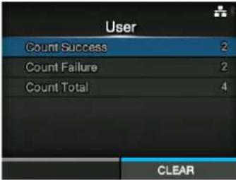 | ||
| 1 Count | Count Success Shows the total number of successful times you have written to an RFID tag after the RFID counter is cleared. | ||
| 2 Count | Failure Shows the total number of RFID write errors after the RFID counter is cleared. | ||
| 3 Count | Total Shows the total number of times you have written to an RFID tag after the RFID counter is cleared.This is the total number including Count Success and Count Failure. | ||
| NoteYou can reset the counter using the right soft button (CLEAR) when the counter is 1 or higher. | |||
4.4.4 Applications Menu
In the Applications menu, there are setting items as follows:
Applications
| 1 Protocol Set the printer language. | ||
| 2 | SBPL | Set the SBPL printer command. |
| 3 | SZPL | Set the SZPL printer command. |
| 4 | SIPL | Set the SIPL printer command. |
| 5 | STCL | Set the STCL printer command. |
| 6 | SDPL | Set the SDPL printer command. |
| 7 | AEP | Set the functions for AEP (Application Enabled Printing). |
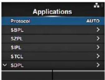
Protocol
Applications > Protocol
Set the printer language.
The options are as follows:
- AUTO: Automatically analyze the received print data and set the printer language. In Auto mode, the printer can change the language after startup by receiving another language.
- SBPL: Set when you use the SBPL printer language or XML.
- SZPL: Set when you use the SZPL printer language.
• SIPL: Set when you use the SIPL printer language. - SDPL: Set when you use the SDPL printer language.
• STCL: Set when you use the STCL printer language.
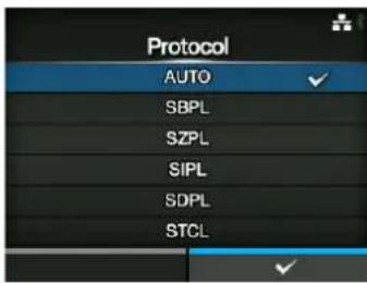
Note (When AUTO is selected in the Protocol menu)
- When AUTO is selected, the message prompting to restart the printer will appear on the online/offline screen. In such a case, reboot the printer to make the setting effective.
- Once the printer language is fixed, the name of the printer language will appear on the online/offline screen. The area to show the name of the printer language will remain blank until the printer language is finalized.
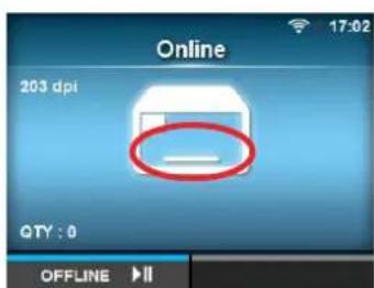
The area remains blank until the printer language is finalized.
For example, send print data in SBPL.
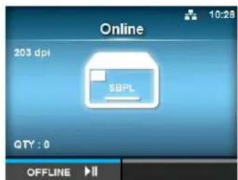
- Printer language is finalized with the received print data.
- Non-Standard Code is not supported. When Standard Code under SBPL in the Applications menu is disabled, the Protocol setting will be changed to SBPL.
SBPL
Applications > SBPL
SBPL (Sato Barcode Printer Language) is the common command that controls SATO barcode label printers.
To use SBPL as the printer command, set the following items:
| 1 Show Error Enable or disable the command error indication. | |
| 2 Standard Code Set the protocol code. | |
| 3 Orientation Set the layout for printing. | |
| 4 Font Settings Set the font. | |
| 5 Compatible Set the compatible code. |
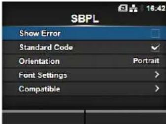
Show Error
Applications > SBPL > Show Error
Enable or disable the command error indication when incorrect command or parameter is detected in the print data.
The options are as follows:
- Enabled: Enable the command error indication. The command error is shown and the print operation is paused when incorrect command or parameter is detected in the print data.
- Disabled: Disable the command error indication.
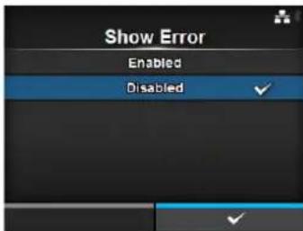
Standard Code
Applications > SBPL > Standard Code
Set the protocol code.
The options are as follows:
- Enabled: Use a standard code.
• Disabled: Use a non-standard code.
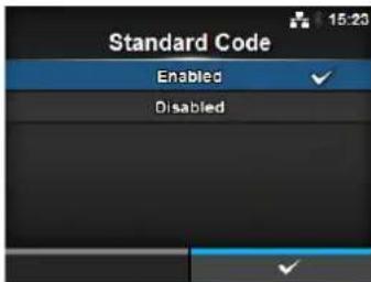
Note
- The message prompting to restart the printer will appear on the online/offline screen if you have made any changes. In such a case, reboot the printer to make the setting effective.
- When AUTO is selected in the Protocol menu while Disabled is selected, the setting will be changed to Enabled.
Orientation
Applications > SBPL > Orientation
Select the layout for printing the label.
- Portrait: Use a portrait layout. (No rotation)
- Landscape: Use a landscape layout. (90-degree rotation)
- Inv. Portrait: Use an inverse portrait layout. (180-degree rotation)
- Inv. Landscape: Use an inverse landscape layout. (270-degree rotation)

Font Settings
Applications > SBPL > Font Settings
Set the font.
The setting items are as follows:
1 Zero Slash Set the type for printing zero.
2 Kanji Set the kanji code to be used.
3 Proportional Set the character pitch for printing.
4 Code Page Set the code page to be used.
5 € Set the European currency symbol to a hex code.
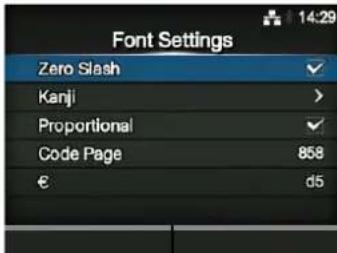
Zero Slash
Applications > SBPL > Font Settings > Zero Slash
Set whether to print the number zero (0) with or without a slash (/).
This setting is applied to the following bitmap fonts:
U, S, M, WB, WL, XU, XS, XM, XL, X20, X21, X22, X23, X24
The options are as follows:
- Enabled: Print zero with a slash.
- Disabled: Print zero without a slash.
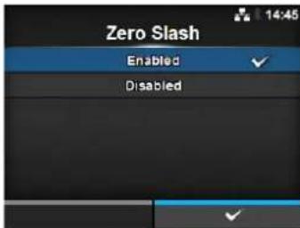
Kanji
| Applications > SBPL > Font Settings > KanjiSet the kanji code to be used.The setting items are as follows: | 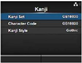 | ||
| 1 Kanji Set Set the kanji code to be used. | |||
| 2 Character Code Set the character code to be used. | |||
| 3 Kanji Style Set the font to be used. | |||
Kanji Set
| Applications > SBPL > Font Settings > Kanji > Kanji SetSet the kanji code to be used.The options are as follows:JP - COMPATIBLEJP-JISX0208JP-JISX0213GB18030BIG 5KCS5601 | 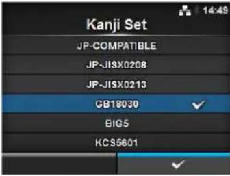 |
Character Code
| Applications > SBPL > Font Settings > Kanji > Character CodeSet the character code to be used.The options vary depending on the kanji code set in the Kanji Set:When set to JP-COMPATIBLE or JP-JISX0208JISSJ ISUTF-16When set to JP-JISX0213SJ ISUTF-16When set to GB18030GB18030When set to BIG5BIG 5When set to KCS5601KCS5601 | 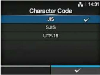 |
Kanji Style
Applications > SBPL > Font Settings > Kanji > Kanji Style
Set the font to be used.
The options are as follows:
• Mincho
• Gothic

Proportional
Applications > SBPL > Font Settings > Proportional
Set whether to print each character using a proportional pitch or fixed pitch.
The options are as follows:
- Enabled: Print each character with a proportional pitch.
- Disabled: Print all characters with a fixed pitch.
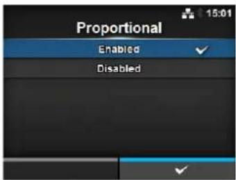
Code Page
Applications > SBPL > Font Settings > Code Page
Select the code page to be used from the list.
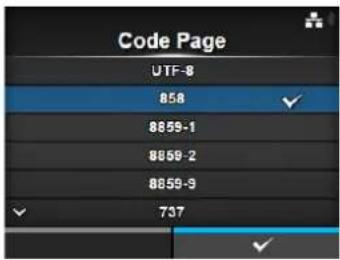
€
Applications > SBPL > Font Settings > €
Set the European currency symbol to a hex code.
The setting range is from 00 to ff (hexadecimal).
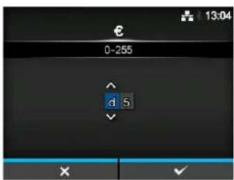
| Compatible | |||
| Applications > SBPL > CompatibleSet the compatible code for SBPL.The setting items are as follows: | 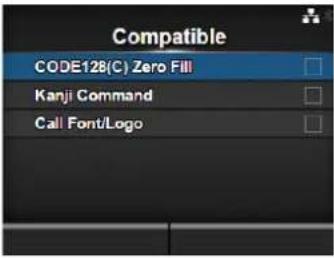 | ||
| 1 CODE128(C)Zero Fill | Set whether to allow odd digits and print the barcode with zero-filling when start code C is used in CODE128. | ||
| 2 Kanji Command Set the | printer behavior when the received data includes the Kanji command ESC+K5, ESC+K6 or ESC+K7. | ||
| 3 Call Font/Logo Set how | to process the character code specified in Recall font & logo command (ESC+RF). | ||
| CODE128(C) Zero Fill | |
| Applications > SBPL > Compatible > CODE128(C) Zero FillSet whether to allow odd digits and print the barcode with zero-filling in case start code C is used in CODE128.The options are as follows:Enabled: Allow odd digits and print the barcode with zero-filling.Disabled: Do not allow odd digits. A command error occurs and the barcode will not be printed. | 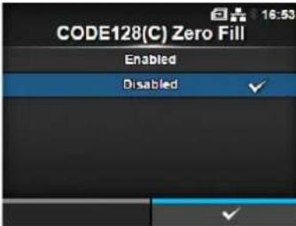 |
| Kanji Command | |
| Applications > SBPL > Compatible > Kanji CommandSet the printer behavior when the received data includes the Kanji command ESC+K5, ESC+K6 or ESC+K7.The options are as follows:Enabled: Change the Kanji commands ESC+K5, ESC+K6 and ESC+K7 in the received data to the proper commands and print. ESC+K5: 16x16 dots Kanji in horizontal line with 1-byte character ESC+K6: 24x24 dots Kanji in horizontal line with 1-byte character ESC+K7: 22x22 dots Kanji in horizontal lineDisabled: Do not change the Kanji commands ESC+K5, ESC+K6 and ESC+K7 in the received data. The printer behavior when it receives these commands is as follows:ESC+K5: Print with 40x40 dots Kanji in horizontal line.ESC+K6: A command error occurs and the data will not be printed.ESC+K7: A command error occurs and the data will not be printed. | 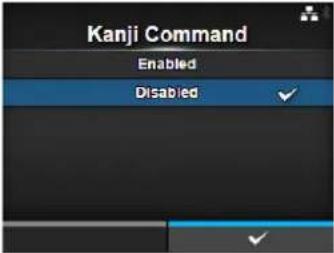 |
Call Font/Logo
Applications > SBPL > Compatible > Call Font/Logo
Set how to process the character code specified in Recall font & logo command (ESC+RF).
The options are as follows:
- Enabled: Character codes are processed in little-endian format.
- Disabled: Character codes are processed in big-endian format.
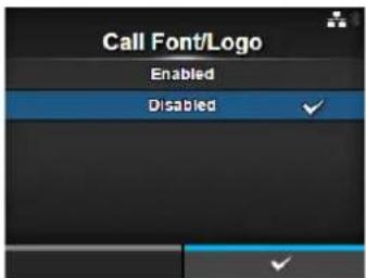
SZPL
Applications > SZPL
To use SZPL as the printer command, set the following items:
1 Label Set the print position.
2 Caret Set the caret (^) code.
3 Delimiter Set the delimiter (,) code.
4 Tilde Set the tilde (\~) code.
5 Clock Format Set the date format.
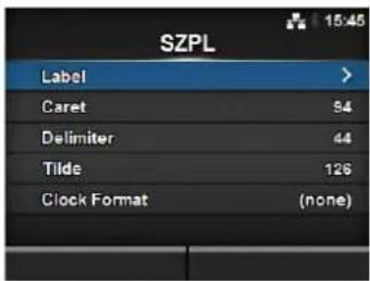
Label
Applications > SZPL > Label
Set the print position.
The setting items are as follows:
1 Shift Set the shift offset position of the label.
2 Top Set the top offset position of the label.
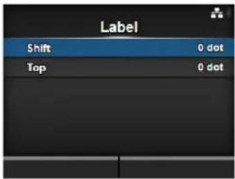
Shift
Applications > SZPL > Label > Shift
Set the shift offset position of the label.
The setting range varies depending on the print resolution of the printer.
The setting range is as follows:
• 203 dpi: -832 to 0 to 832 dots
• 305 dpi: -1248 to 0 to 1248 dots
• 609 dpi: -2496 to 0 to 2496 dots
• 203 dpi: -832 to 0 to 832 dots
• 305 dpi: -1248 to 0 to 1248 dots
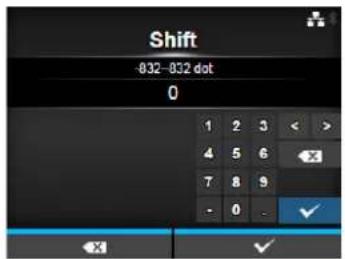
Top
Applications > SZPL > Label > Top
Set the top offset position of the label. The setting range is from -120 to 0 to 120.
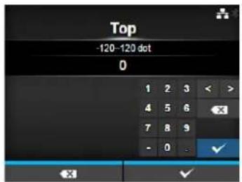
Caret
Applications > SZPL > Caret Set the caret (^) code. The setting range is from 0 to 255.
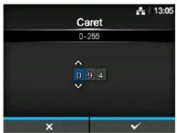
Delimiter
Applications > SZPL > Delimiter
Set the delimiter (,) code.
The setting range is from 0 to 255.
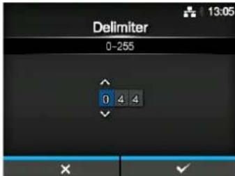
Tilde
Applications > SZPL > Tilde
Set the tilde (\~) code.
The setting range is from 0 to 255.
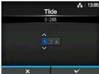
Clock Format
Applications > SZPL > Clock Format
Set the date format.
The options are as follows:
- (none)
• MM/DD/YY (24-hour clock)
• MM/DD/YY (12-hour clock)
• DD/MM/YY (24-hour clock)
• DD/MM/YY (12-hour clock)
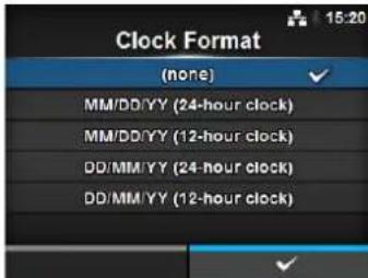
SIPL
Applications > SIPL
To use SIPL as the printer command, set the following items:
1 Font Settings Set the font.
2 Format Save Set whether to save the user format data registered at printing in the printer.
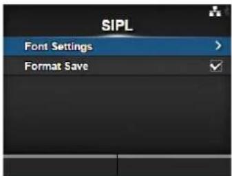
Font Settings
| Applications > SIPL > Font SettingsSet the font.The setting items are as follows: | ||
| 1 Code Page Set the code page to be used. | ||
| 2 c20 Proportional Pitch | Set the character pitch for printing. | |
| 3 0 $lash Set the type for | printing zero. | |

Code Page
| Applications > SIPL > Font Settings > Code Page |
| Select the code page to be used from the list. |
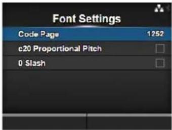
c20 Proportional Pitch
| Applications > SIPL > Font Settings > c20 Proportional Pitch |
| Set whether to print each character using a proportional pitch or fixed pitch. |
| The options are as follows: |
| • Enabled: Print each character with a proportional pitch. |
| • Disabled: Print all characters with a fixed pitch. |
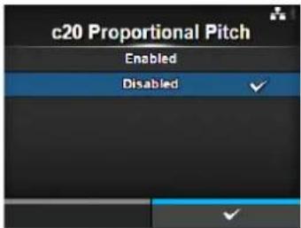
0 Slash
| Applications > SIPL > Font Settings > 0 Slash |
| Set whether to print the number zero (0) with or without a slash (/).The options are as follows:Enabled: Print zero with a slash disabled: Print zero without a slash. |
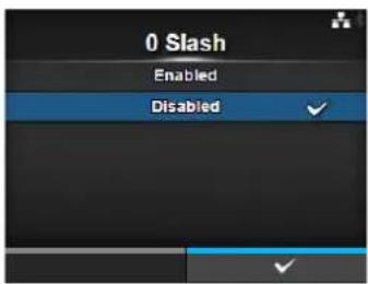
Format Save
Applications > SIPL > Format Save
Set whether to save the user format data registered at printing in the printer.
The options are as follows:
- Enabled: Save the user format data registered at printing in the printer.
- Disabled: Do not save the user format data registered at printing in the printer. The user format data remains in the printer memory until the printer is powered off. You need to register a user format again after reboot.
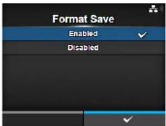
STCL
Applications > STCL
To use STCL as the printer command, set the following items:
1 Command Head Set the command head.
2 Font Settings Set the font.
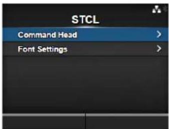
Command Head
Applications > STCL > Command Head
Set the command head.
The setting items are as follows:
1 Control Code Set the control code.
2 1st Byte Code Set the first byte code.
3 2nd Byte Code Set the second byte code.
4 3rd Byte Code Set the third byte code.
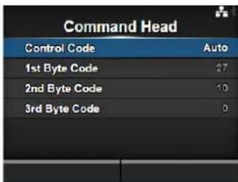
Control Code
Applications > STCL > Command Head > Control Code
Set the control code.
The options are as follows:
• Auto: Perform the protocol detection automatically.
- ESC|LF|NUL
• 7 B | 7 C | 7 D
- Custom: Change the first to third byte codes.
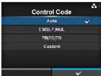
1st Byte Code
Applications > STCL > Command Head > 1st Byte Code
Set the first byte code.
You can change the code only if you have selected Custom in the Control Code menu.
The setting range is from 0 to 255.
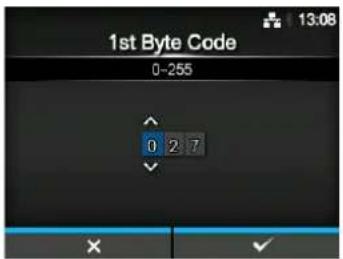
2nd Byte Code
Applications > STCL > Command Head > 2nd Byte Code
Set the second byte code.
You can change the code only if you have selected Custom in the Control Code menu.
The setting range is from 0 to 255.
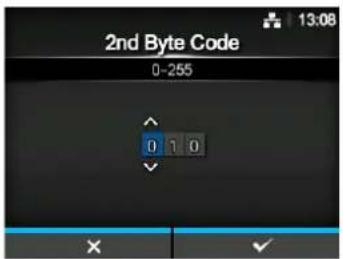
3rd Byte Code
Applications > STCL > Command Head > 3rd Byte Code
Set the third byte code.
You can change the code only if you have selected Custom in the Control Code menu.
The setting range is from 0 to 255.
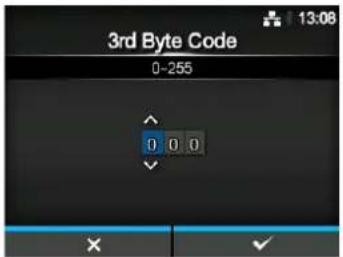
Font Settings
Applications > STCL > Font Settings
Set the font.
The setting items are as follows:
1 Zero Slash Set the type for printing zero.
2 € Set the European currency symbol to a hex code.
3 Code Page Set the code page to be used.
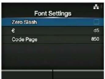
Zero Slash
Applications > STCL > Font Settings > Zero Slash
Set whether to print the number zero (0) with or without a slash (/). The options are as follows:
- Enabled: Print zero with a slash.
- Disabled: Print zero without a slash.
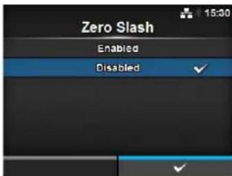
€
Applications > STCL > Font Settings > €
Set the European currency symbol to a hex code. The setting range is from 00 to ff (hexadecimal).
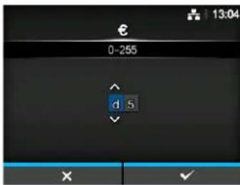
Code Page
Applications > STCL > Font Settings > Code Page
Select the code page to be used from the list.
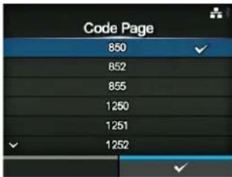
SDPL
Applications > SDPL
To use SDPL as the printer command, set the following items:
1 Control Code Set the control code.
2 Label Rotation Set the page orientation of label printing.
3 Format Attribute Set the format attribute.
4 Pause Mode Enable or disable the pause mode.
5 SOP Emulation Set the SOP emulation.
6 1 Byte Codepage Select the code page to be used for 1 byte characters.
7 SDPL Measure Unit Set the measurement unit.
8 Compatible Mode Set the compatible mode for SDPL.
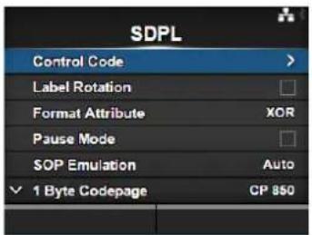
Control Code
Applications > SDPL > Control Code
Set the control code.
The setting items are as follows:
1 Code Type Set the type of the control code.
2 SOH Set the SOH code.
3 STX Set the STX code.
4 CR Set the CR code.
5 CNTBY Set the CNTBY code.
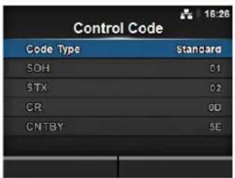
Code Type
Applications > SDPL > Control Code > Code Type
Set the control code type.
The options are as follows:
- Standard
- Alternate 1
- Alternate 2
- Custom
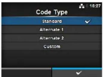
SOH
Applications > SDPL > Control Code > SOH
Set the SOH code.
You can change the code only if you have selected Custom in the Code
Type menu.
The setting range is from 00 to ff (hexadecimal).
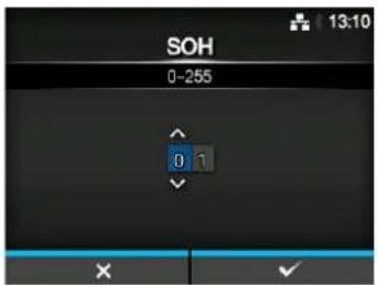
STX
Applications > SDPL > Control Code > STX
Set the STX code.
You can change the code only if you have selected Custom in the Code Type menu.
The setting range is from 00 to ff (hexadecimal).
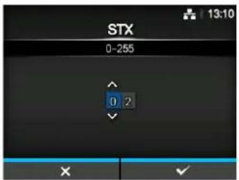
CR
Applications > SDPL > Control Code > CR
Set the CR code.
You can change the code only if you have selected Custom in the Code Type menu.
The setting range is from 00 to ff (hexadecimal).
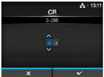
CNTBY
Applications > SDPL > Control Code > CNTBY
Set the CNTBY code.
You can change the code only if you have selected Custom in the Code Type menu.
The setting range is from 00 to ff (hexadecimal).
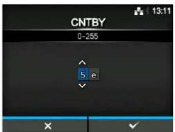
Label Rotation
Applications > SDPL > Label Rotation
Set the page orientation of label printing.
The options are as follows:
- Enabled: Labels are printed in inverse-portrait orientation.
- Disabled: Labels are printed in normal portrait orientation.
Format Attribute
Applications > SDPL > Format Attribute
Set the format attribute.
The options are as follows:
• XOR
- Transparent
- Opaque
- Inverse
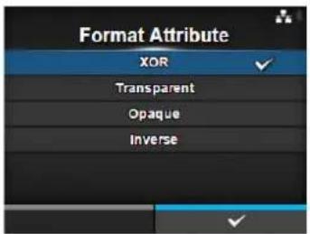
Pause Mode
Applications > SDPL > Pause Mode
Enable or disable the pause mode.
The options are as follows:
- Enabled: Enable the pause mode.
- Disabled: Disable the pause mode.
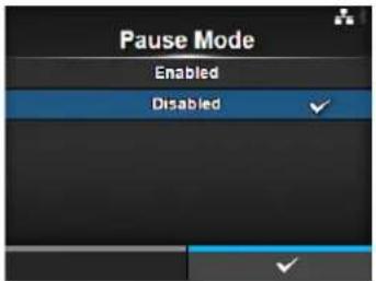
SOP Emulation
Applications > SDPL > SOP Emulation
Set the SOP emulation.
The options are as follows:
- Disabled
• Prodigy Plus - 110
• Allegro - 220
• Prodigy - 250
• Auto
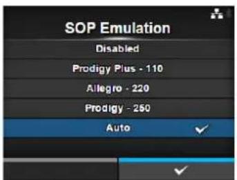
1 Byte Codepage
Applications > SDPL > 1 Byte Codepage
Select the code page to be used for 1 byte characters from the list.
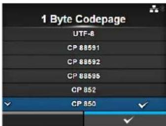
SDPL Measure Unit
Applications > SDPL > SDPL Measure Unit
Set the measurement unit.
The options are as follows:
- Inch
- Millimeter
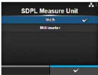
Compatible Mode
Applications > SDPL > Compatible Mode
Set the compatible mode for SDPL.
The setting item is as follows:
1 TTF Set whether to allow the use of TrueType fonts.
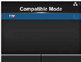
TTF
Applications > SDPL > Compatible Mode > TTF
Set whether to allow the use of TrueType fonts.
The options are as follows:
- Enabled: Allow the use of TrueType fonts.
- Disabled: Do not allow the use of TrueType fonts.
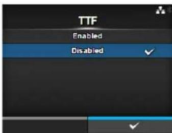
AEP
Applications > AEP
Set the functions for AEP (Application Enabled Printing).
AEP mode allows you to use the printer as a stand-alone printer by running applications within the printer.
Use the standard application, or install custom applications to the printer from a USB memory, All-In-One Tool, WebConfig page, etc.
In AEP mode, you can use USB keyboards and barcode scanners to input data.
The setting items are as follows:
| 1 Enable Enable or disable AEP mode. | |
| 2 Start Application Select | the application to start at printer startup in AEP mode. |
Note
Contact your SATO sales representative for more information about the use of AEP mode.
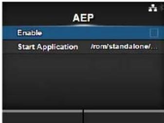
Enable
Applications > AEP > Enable
Enable or disable AEP mode.
The options are as follows:
- Enabled: Enable AEP mode.
- Disabled: Disable AEP mode.
Note
The message prompting to restart the printer will appear on the online/offline screen if you have made any changes. In such a case, reboot the printer to make the setting effective.
Start Application
Applications > AEP > Start Application
Select the application to start at printer startup in AEP mode.
Select the application using the ▲/▼ buttons and press the right soft button to confirm.
4.4.5 System Menu
In the System menu, there are setting items as follows:
| System | |||
| 1 Regional Set the display language, time zone, calendar and unit. |  | ||
| 2 | Notifications | Set the function to notify when to perform cleaning and parts replacement. | |
| 3 | Sound | Set the buzzer sound. | |
| 4 | Energy Saving | Set the period before the printer enters sleep mode. | |
| 5 | LCD Brightness | Set the brightness of the screen. | |
| 6 | Show Total Count | Enable or disable the indication of the total print count. | |
| 7 | Password | Set the password. | |
| 8 | Start on AC | Set whether to power on/off the printer by powering on/off the main power source. | |
| Regional | |||
| System > RegionalSet the display language, time zone, calendar and unit.The setting items are as follows: |  | ||
| 1 Messages Set the display language of the LCD. | |||
| 2 USB Keyboard Set the input language when you connect a USB keyboard to the printer. | |||
| 3 Locale Set the locale to be used in AEP mode. | |||
| 4 Unit Set the unit of length for indication. | |||
| 5 Time Set the time. | *You can set the time only if you have installed the optional RTC kit. | ||
| 6 Date Set the date. | *You can set the date only if you have installed the optional RTC kit. | ||
| 7 Time Zone Set the time zone. | |||
Messages
System > Regional > Messages
Set the display language of the LCD.
Select the display language from the list.
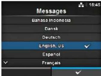
USB Keyboard
System > Regional > USB Keyboard
Set the input language when you connect a USB keyboard to the printer. Select the input language from the list.
Note
Only Western and East European languages are supported for data input from USB keyboards.
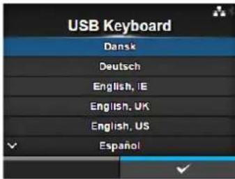
Locale
System > Regional > Locale
Set the locale to be used in AEP mode.
This setting determines the format of time, dates, numbers, prices, names of weekdays, months, etc. in AEP applications.
Select the locale from the list.
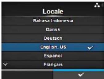
Unit
System > Regional > Unit
Set the unit of length for indication.
The options are as follows:
- dot
- " (inch)
• mm
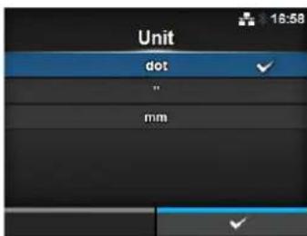
Time
System > Regional > Time
Set the time.
You can set the time only if you have installed the optional RTC kit.
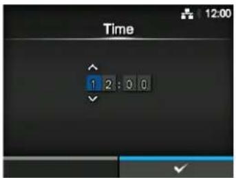
Date
System > Regional > Date
Set the date.
You can set the date only if you have installed the optional RTC kit. The setting range is from 2000-01-01 to 2035-12-31.
*The date format is Year - Month - Date.
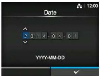
Time Zone
System > Regional > Time Zone > Region > City
Set the time zone.
First select the region from the Region list. Then select the city from the City list.
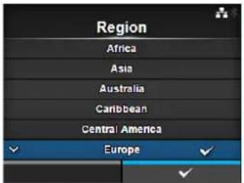
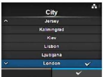
| Notifications | |||
| System > NotificationsSet the function to notify the timing of cleaning and parts replacement.The setting items are as follows: | 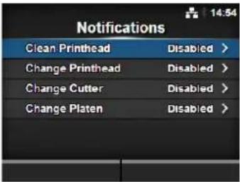 | ||
| 1 Clean Printhead Notify when the print head needs to be cleaned. | |||
| 2 Change Printhead Notify when the print head needs to be replaced. | |||
| 3 Change Cutter Notify when the cutter unit needs to be replaced. | |||
| 4 Change Platen Notify when the platen roller needs to be replaced. | |||
| Clean Printhead | |||
| System > Notifications > Clean PrintheadNotify when the print head needs to be cleaned.The setting items are as follows: | 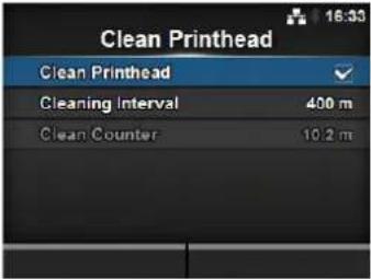 | ||
| 1 Clean Printhead Enable | or disable the notification function aboutwhen the print head needs to be cleaned. | ||
| 2 Cleaning Interval Set the | notification interval about when the printhead needs to be cleaned. | ||
| 3 Clean Counter Shows the current print distance. | |||
| Clean Printhead | |
| System > Notifications > Clean Printhead > Clean PrintheadEnable or disable the notification function about when the print head needs to be cleaned.The options are as follows:Enabled: Enable the notification function.Disabled: Disable the notification function. | 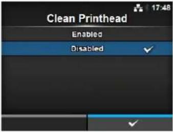 |
Cleaning Interval
System > Notifications > Clean Printhead > Cleaning Interval
Set the notification interval about when the print head needs to be cleaned. Available to change only if you have selected Enabled in the Clean Printhead menu.
The printer shows the print distance as a setting value. The setting range is from 10 to 1000 m.
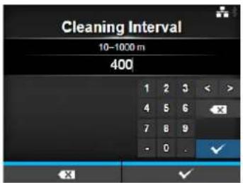
Change Printhead
System > Notifications > Change Printhead
Notify when the print head needs to be replaced. The setting items are as follows:
| 1 Change Printhead Enable or disable the notification function about when the print head needs to be replaced. | |
| 2 Printhead Interval Set the notification interval about when the print head needs to be replaced. | |
| 3 Printhead Count Shows the current print distance. |
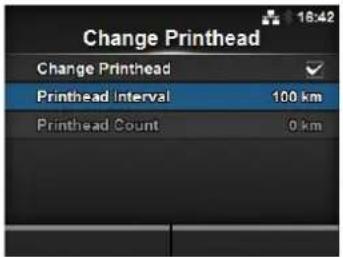
Change Printhead
System > Notifications > Change Printhead > Change Printhead
Enable or disable the notification function about when the print head needs to be replaced.
The options are as follows:
- Enabled: Enable the notification function.
- Disabled: Disable the notification function.
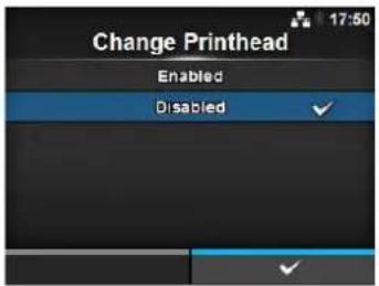
Printhead Interval
System > Notifications > Change Printhead > Printhead Interval
Set the notification interval about when the print head needs to be replaced.
Available to change only if you have selected Enabled in the Change Printhead menu.
The printer shows the print distance as the setting value.
The setting range is from 10 to 100 km.
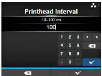
| Change Cutter | |||
| System > Notifications > Change CutterNotify when the cutter unit needs to be replaced.The setting items are as follows: | 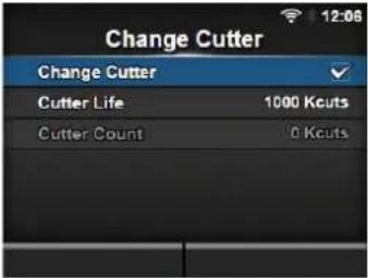 | ||
| 1 Change Cutter Enable or disable the notification function aboutwhen the cutter unit needs to be replaced. | |||
| 2 Cutter Life Set the notification interval about when thecutter unit needs to be replaced. | |||
| 3 Cutter Count Shows the current number of cuts by the cutter. | |||
| Change Cutter | |
| System > Notifications > Change Cutter > Change CutterEnable or disable the notification function about when the cutter unit needs to be replaced.The options are as follows:Enabled: Enable the notification function.Disabled: Disable the notification function. | 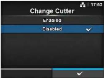 |
| Cutter Life | |
| System > Notifications > Change Cutter > Cutter LifeSet the notification interval about when the cutter unit needs to be replaced.Available to change only if you have selected Enabled in the Change Cutter menu.The printer shows the cutter count as the setting value.The setting range is from 10 to 1000 Kcuts. | 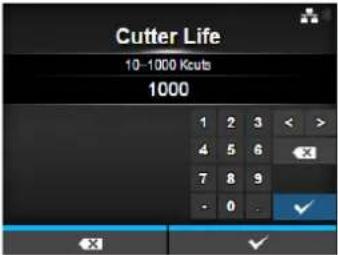 |
| Change Platen | |||
| System > Notifications > Change PlatenNotify when the platen roller needs to be replaced.The setting items are as follows: | 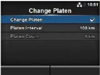 | ||
| 1 Change Platen Enable or disable the notification function aboutwhen the platen roller needs to be replaced. | |||
| 2 Platen Interval Set the notification interval about when theplaten roller needs to be replaced. | |||
| 3 Platen Count Shows the current distance the platen roller hasfed. | |||
Change Platen
System > Notifications > Change Platen > Change Platen
Enable or disable the notification function about when the platen roller needs to be replaced.
The options are as follows:
- Enabled: Enable the notification function.
- Disabled: Disable the notification function.
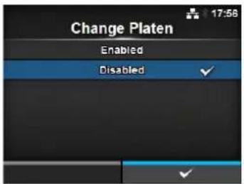
Platen Interval
System > Notifications > Change Platen > Platen Interval
Set the notification interval about when the platen roller needs to be replaced.
Available to change only if you have selected Enabled in the Change Platen menu.
The printer shows the fed distance as the setting value.
The setting range is from 10 to 100 km.
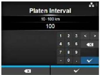
Sound
System > Sound
Set the buzzer sound.
The setting item is as follows:
1 Error Sound Set the buzzer volume for the error sound.
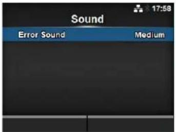
Error Sound
System > Sound > Error Sound
Set the buzzer volume for the error sound.
The options are as follows:
- Off: Mute the sound.
- Low: Low volume.
• Medium: Medium volume.
• High: High volume.
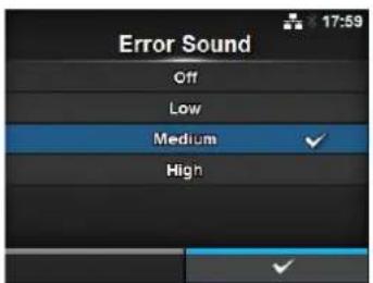
| Energy Saving | |||
| System > Energy SavingThe setting items are as follows: |  | ||
| 1 Sleep Timeout Set the period before the printer enters sleep mode. | |||
| Sleep Timeout | |
| System > Energy Saving > Sleep TimeoutSet the period before the printer enters sleep mode.The setting range is from 0 to 60 minutes. | 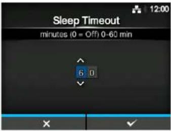 |
| NoteThe sleep function is disabled if you set to 0.This setting is disabled ifExternal I/O on page 155is set to Enable. | |
| LCD Brightness | |
| System > LCD BrightnessSet the brightness of the screen.The setting range is from 0 to 9.0 is the darkest and 9 is the brightest.Press the right soft button to complete the setting. | 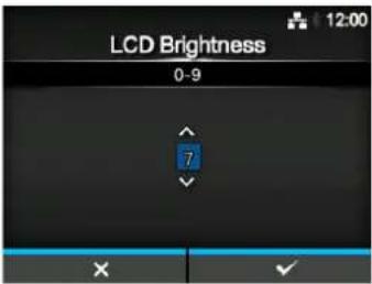 |
| NoteThe printer has a built-in energy saving function, which will decrease the brightness of the screen when you have not operated the printer for a period. | |
Show Total Count
System > Show Total Count
Enable or disable the indication of the total print count.
If set to Enabled, the total print count shows on both the Online and Offline screens.
The number in the brackets to the right of "QTY" on the Online and Offline screens is the total print count.
The options are as follows:
- Enabled: Enable the indication of the total print count.
- Disabled: Disable the indication of the total print count.
Note
Shows the total print count from the time the printer is on until it is off. When you power off the printer, the count resets to 0.
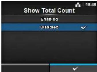
Password
System > Password
The setting items are as follows:
1 Password Enable Enable or disable the password setting.
2 Install Security Enable or disable the password input for the package file download.
3 Change Password Change the password.
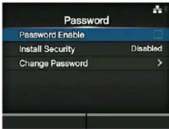
Password Enable
System > Password > Password Enable
Enable or disable the password setting.
If you have set the password to Enabled, the printer requires you to enter the password set in the Password screen before you enter the Settings menu.
The options are as follows:
- Enabled: Enable the password setting.
- Disabled: Disable the password setting.
Note
The default password is 0310. You can change the password in Password > Change Password > level1.
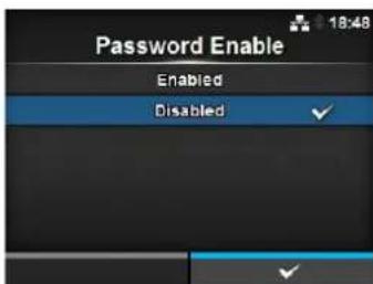
Install Security
System > Password > Install Security
Enable or disable the password input for installing the pkg file to the printer.
If you have set the password to Enabled, the printer requires you to enter the password set in the Password screen before you can download the package file.
The options are as follows:
- Disabled: No password is required to install a pkg file.
- USB: Password is required to install a pkg file from the USB memory.
- Always: Password is required to install a pkg file from the USB memory or downloaded from computer.
Note
The password used for installing a pkg file can be any passwords set in the System > Password.
Contact a SATO reseller or technical service center for more information of the pkg file.
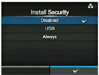
Change Password
System > Password > Change Password
Change the password.
You can enter 4 to 32 characters including alphabet (capital and small letters), numbers and symbols.
The setting items are as follows:
- admin: This is the setting item for factory.
Strictly for SATO authorized personnel use. - manager: The password for accessing the Service menu.
Strictly for SATO authorized personnel use.
• level1: The password for accessing the Setting menu. - rfid: This is the setting item for factory.
Strictly for SATO authorized personnel use.
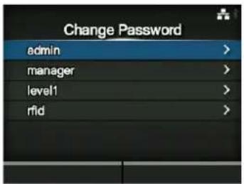
Note
The admin, manager and rfid passwords are for factory and maintenance personnel. You cannot change these passwords.
Change Password
Reset Passwords
If you have forgotten the customized password, you can reset it back to the default password.
-
Power off the printer.
-
Press and release the ⏻ power button while pressing and holding the ➕ back button, ◀ and ▶ buttons simultaneously until the online/offline screen shows. All the passwords are reset to default passwords.
Note
This key sequence allows users to access the settings menu with the default passwords as a temporary solution.
After accessing the settings menu with the default password, you must customize the password again.
Start on AC
System > Start on AC
Set whether to power on/off the printer by powering on/off the main power source.
The options are as follows:
- Enabled: Power on/off the printer by powering on/off the main power source.
- Disabled: Power on/off the printer by pressing the ⏻ power button of the printer.
CAUTION
- Do not repeatedly power on and off the printer.
- If you power the main power source off and then on again quickly, the printer may not be powered on because it is still in the powering off process. In such a case, press the power button to power on the printer.
- Do not power off the printer during operation, such as when printing or updating. Doing so could cause a malfunction of the printer.
- Do not disconnect the power cord until the powering off process is completed on the printer.
- An incorrect power on/off operation may damage the printer settings. In such a case, the printer settings are reset to their default values.
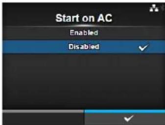
4.4.6 Tools Menu
In the Tools menu, there are setting items as follows:
| Tools | |||
| 1 Test Print Perform a test print. | 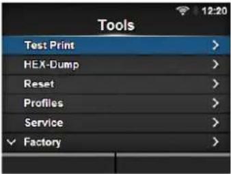 | ||
| 2 | HEX-Dump | Save the hex dump print data or dump data from the receive buffer to the USB memory. | |
| 3 | Reset | Initialize the configuration or counter of the printer. | |
| 4 | Profiles | Utilize the printer configurations as profiles. | |
| 5 | Service | These are the setting items for service. Strictly for SATO authorized service personnel use. | |
| 6 | Factory | These are the setting items for factory. Strictly for SATO factory personnel use. | |
| 7 | Certificates | Set the wireless LAN authentication.* Available only if you have installed the USB memory. | |
| 8 | Barcode Reader | Set the barcode check function using a barcode verifier. | |
| 9 | Clone | Copy the current printer settings and data to the USB memory.* Available only if you have installed the USB memory. | |
| 10 | Startup Guide | Enable or disable the startup guide. | |
| Test Print | |||
| Tools > Test PrintPerform a test print.The setting items are as follows: | 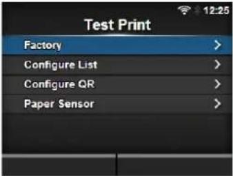 | ||
| 1 Factory Perform the factory test print. | |||
| 2 Configure List Print the configuration information of the printer. | |||
| 3 Configure QR Print the configuration information with a QR code. | |||
| 4 Paper Sensor Print the detection result of the media sensor level. | |||
| Factory | |||
| Tools > Test Print > FactoryPerform the factory test print.1. Check and set the items as listed on the Factory menu.2. Press the right soft button to start the test print. Press the right soft button again to pause the print.To stop the test print, first pause the print and then press the ➕ button.The setting items are as follows. | 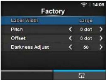 | ||
| 1 Label Width Shows the | necessary media width of the test print.The necessary media width is 101.6 mm (4") for Large. | ||
| 2 Pitch Set the print position in the vertical direction.The setting range varies depending on the print resolution of the printer.The setting range is as follows:203 dpi: -30 to 0 to 30 dots305 dpi: -45 to 0 to 45 dots609 dpi: -90 to 0 to 90 dots203 dpi: -30 to 0 to 30 dots305 dpi: -45 to 0 to 45 dotsWhen you decrease the setting value, the print position moves in the feed direction (toward the front part of the media).When you increase the setting value, the print position moves opposite the feed direction (toward the end part of the media). | NoteThe value of Pitch, Offset and Darkness Adjust set in the Factory menu will reflect to the same item settings in the Configure List menu, Configure QR menu and Paper Sensor menu. | ||
| 3 Offset Set the stop position of the media.The setting range varies depending on the print resolution of the printer.The setting range is as follows:203 dpi: -30 to 0 to 30 dots305 dpi: -45 to 0 to 45 dots609 dpi: -90 to 0 to 90 dots203 dpi: -30 to 0 to 30 dots305 dpi: -45 to 0 to 45 dots when you decrease the setting value, the stop position moves in the feed direction (toward the front part of the media).When you increase the setting value, the stop position moves opposite the feed direction (toward the end part of the media). | |||
| 4 Darkness Adjust Fine tune the print darkness of the test print.0 is the lightest and 99 is the darkest. | |||
| Configure List | |||
| Tools > Test Print > Configure ListPrint the configuration information of the printer.1. Check and set the items as listed on the Configure List menu.2. Press the right soft button to start the test print. Press the right soft button again to pause the print.To stop the test print, first pause the print and then press the ∨ button.The setting items are as follows. | 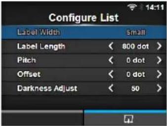 | ||
| 1 Label Width Shows the necessary media width of the test print.The necessary media width is 50.8 mm (2") for Small. | |||
| 2 Label Length Set the length of one piece of the media used for the test print.The setting range varies depending on the print resolution of the printer.The setting range is as follows:203 dpi: 400 to 1600 dots305 dpi: 600 to 2400 dots609 dpi: 1200 to 4800 dots203 dpi: 400 to 1600 dots305 dpi: 600 to 2400 dots | NoteThe value of Label Length, Pitch, Offset and Darkness Adjust set in the Configure List menu will reflect to the same item settings in the Factory menu, Configure QR menu and Paper Sensor menu. | ||
| 3 Pitch Set the print position in the vertical direction.The setting range varies depending on the print resolution of the printer.The setting range is as follows:203 dpi: -30 to 0 to 30 dots305 dpi: -45 to 0 to 45 dots609 dpi: -90 to 0 to 90 dots203 dpi: -30 to 0 to 30 dots305 dpi: -45 to 0 to 45 dotsWhen you decrease the setting value, the print position moves in the feed direction (toward the front part of the media).When you increase the setting value, the print position moves opposite the feed direction (toward the end part of the media). | |||
| 4 Offset Set the stop position of the media.The setting range varies depending on the print resolution of the printer.The setting range is as follows:203 dpi: -30 to 0 to 30 dots305 dpi: -45 to 0 to 45 dots609 dpi: -90 to 0 to 90 dots203 dpi: -30 to 0 to 30 dots305 dpi: -45 to 0 to 45 dotsWhen you decrease the setting value, the stop position moves in the feed direction (toward the front part of the media).When you increase the setting value, the stop position moves opposite the feed direction (toward the end part of the media). | |||
| 5 Darkness Adjust Fine tune the print darkness of the test print.0 is the lightest and 99 is the darkest. | |||
| Configure QR | |||
| Tools > Test Print > Configure QRPrint the configuration information with a QR code.1. Check and set the items as listed on the Configure QR menu.2. Press the right soft button to start the test print. Press the right soft button again to pause the print.To stop the test print, first pause the print and then press the ➕ button.The setting items are as follows. | 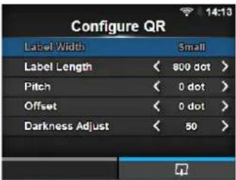 | ||
| 1 Label Width Shows the | necessary media width of the test print.The necessary media width is 50.8 mm (2") for Small. | ||
| 2 Label Length Set the length of one piece of the media used for the test print.The setting range varies depending on the print resolution of the printer.The setting range is as follows:203 dpi: 400 to 1600 dots305 dpi: 600 to 2400 dots609 dpi: 1200 to 4800 dots203 dpi: 400 to 1600 dots305 dpi: 600 to 2400 dots | NoteThe value of Label Length, Pitch, Offset and Darkness Adjust set in the Configure QR menu will reflect to the same item settings in the Factory menu, Configure List menu and Paper Sensor menu. | ||
| 3 Pitch Set the print position in the vertical direction.The setting range varies depending on the print resolution of the printer.The setting range is as follows:203 dpi: -30 to 0 to 30 dots305 dpi: -45 to 0 to 45 dots609 dpi: -90 to 0 to 90 dots203 dpi: -30 to 0 to 30 dots305 dpi: -45 to 0 to 45 dotsWhen you decrease the setting value, the print position moves in the feed direction (toward the front part of the media).When you increase the setting value, the print position moves opposite the feed direction (toward the end part of the media). | |||
| 4 Offset Set the stop position of the media.The setting range varies depending on the print resolution of the printer.The setting range is as follows:203 dpi: -30 to 0 to 30 dots305 dpi: -45 to 0 to 45 dots609 dpi: -90 to 0 to 90 dots203 dpi: -30 to 0 to 30 dots305 dpi: -45 to 0 to 45 dots when you decrease the setting value, the stop position moves in the feed direction (toward the front part of the media).When you increase the setting value, the stop position moves opposite the feed direction (toward the end part of the media). | |||
| 5 Darkness Adjust Fine tune the print darkness of the test print.0 is the lightest and 99 is the darkest. | |||
| Paper Sensor | |||
| Tools > Test Print > Paper SensorPrint the detection result of the media sensor level.1. Check and set the items as listed on the Paper Sensor menu.2. Press the right soft button to start the test print. Press the right soft button again to pause the print.To stop the test print, first pause the print and then press the ➔ button.The setting items are as follows. | 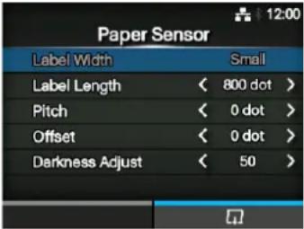 | ||
| 1 Label Width Shows the | necessary media width of the test print.The necessary media width is 101.6 mm (4") for Large and 50.8 mm (2") for Small. | ||
| 2 Label Length Set the length of one piece of the media used for the test print.The setting range varies depending on the print resolution of the printer.The setting range is as follows:203 dpi: 400 to 1600 dots305 dpi: 600 to 2400 dots609 dpi: 1200 to 4800 dots203 dpi: 400 to 1600 dots305 dpi: 600 to 2400 dots | NoteThe value of Label Length, Pitch, Offset and Darkness Adjust set in the Paper Sensor menu will reflect to the same item settings in the Factory menu, Configure List menu and Configure QR menu. | ||
| 3 Pitch Set the print position in the vertical direction.The setting range varies depending on the print resolution of the printer.The setting range is as follows:203 dpi: -30 to 0 to 30 dots305 dpi: -45 to 0 to 45 dots609 dpi: -90 to 0 to 90 dots203 dpi: -30 to 0 to 30 dots305 dpi: -45 to 0 to 45 dotsWhen you decrease the setting value, the print position moves in the feed direction (toward the front part of the media).When you increase the setting value, the print position moves opposite the feed direction (toward the end part of the media). | |||
| 4 Offset Set the stop position of the media.The setting range varies depending on the print resolution of the printer.The setting range is as follows:203 dpi: -30 to 0 to 30 dots305 dpi: -45 to 0 to 45 dots609 dpi: -90 to 0 to 90 dots203 dpi: -30 to 0 to 30 dots305 dpi: -45 to 0 to 45 dotsWhen you decrease the setting value, the stop position moves in the feed direction (toward the front part of the media).When you increase the setting value, the stop position moves opposite the feed direction (toward the end part of the media). | |||
| 5 Darkness Adjust Fine tune the print darkness of the test print.0 is the lightest and 99 is the darkest. | |||
| HEX-Dump | |||
| Tools > HEX-DumpSave the hex dump print data or dump data from the receive buffer to the USB memory.The setting items are as follows: | 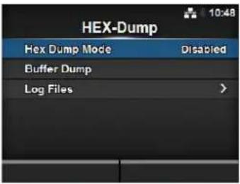 | ||
| 1 Hex Dump Mode Enable or disable the Hex Dump mode. | |||
| 2 Buffer Dump Save the receive buffer data to the printer. | |||
| 3 Log Files Manage the log files of the printer. | |||
Hex Dump Mode
Tools > HEX-Dump > Hex Dump Mode
Enable or disable the Hex Dump mode.
If you set the Hex Dump mode to Enabled, the printer prints the received data and at the same time creates a file of the received data inside "hexdump/".
When you return the setting to Disabled, you can check the file on the screen.
Note
- If you set the Hex Dump mode to Enabled, the design of the online/offline screen changes.
- You can save a maximum of ten received data files for each type of interface. Depending on the file size, the number of files you can save will be less than ten.
- The details of the files created inside "hexdump/" are as follows:
• BT00xx.bin: Received data through Bluetooth.
• LAN00xx.bin: Received data through LAN.
• LPT00xx.bin: Received data through IEEE1284.
• SCI00xx.bin: Received data through RS-232C. - USB00xx.bin: Received data through USB.
- WIFI00xx.bin: Received data through Wi-Fi.
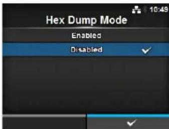
Buffer Dump
Tools > HEX-Dump > Buffer Dump
Save the receive buffer data to the printer.
Available only if you have set to Disabled in the Hex Dump Mode menu. Press the START (right soft) button on the startup screen to save the data to the printer.
Save the receive buffer data to "buff/".
Note
- The data files of the receive buffer are created for each type of interface.
- The details of the file created inside "buff/" are as follows:
• BT0001.bin: The contents of the receive buffer for Bluetooth.
• LAN0001.bin: The contents of the receive buffer for LAN.
• LPT0001.bin: The contents of the receive buffer for IEEE1284.
• SCI0001.bin: The contents of the receive buffer for RS-232C. - USB0001.bin: The contents of the receive buffer for USB.
- WIFI0001.bin: The contents of the received buffer for Wi-Fi.
- If you perform the Buffer Dump again, the existing file will be overwritten.
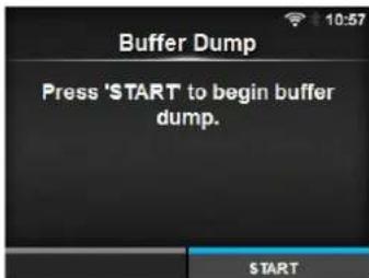
| Log Files | |||
| Tools >HEX-Dump >Log FilesThe setting items are as follows: | 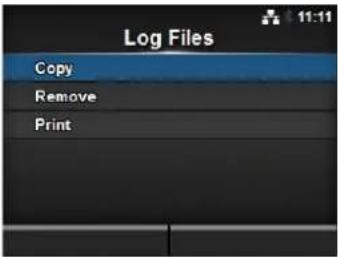 | ||
| 1 Copy Copy the log files | of the printer to the USB memory.* Available only if you have installed the USB memory. | ||
| 2 Remove Delete the log | files of the printer. | ||
| 3 Print Print a hex dump | of the log files of the printer. | ||
Copy
Tools > HEX-Dump > Log Files > Copy
Copy the log files of the printer to the USB memory.
Available only if you have installed the USB memory.
The procedure to copy the log files is as follows:
- Select the file type to copy and press the
button. - buff/: The buffer data saved after you perform the Buffer Dump.
- hexdump/: The received data created through Hex Dump Mode.

- Select the file to copy and press the on the right side of the file name.

button. A checkmark shows
- After you select the file, press the right soft button to copy the selected file to the USB memory.
CAUTION
Be sure to perform a virus check for the USB memory before connecting it to the printer. SATO Corporation shall not be held responsible for a malfunction of the printer caused by a virus infection through the USB memory.
Note
When Hex Dump Mode is set to Enabled, it may take some time before the files are shown.
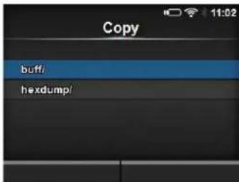
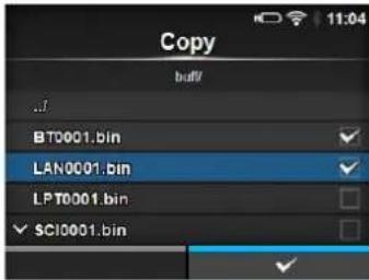
4 Operation and Configuration
Remove
Tools > HEX-Dump > Log Files > Remove
Delete the log files of the printer.
The procedure to delete the log files is as follows:
- Select the file type to delete and press the button.
- buff/: The buffer data saved after you perform the Buffer Dump.
- hexdump/: The received data created through Hex Dump Mode.
- Select the file to delete and press the button. A checkmark shows on the right side of the file name.
- After you select the file, press the right soft button to delete the selected file.
Note
When Hex Dump Mode is set to Enabled, it may take some time before the files are shown.
Tools > HEX-Dump > Log Files > Print
Print a hex dump of the log files of the printer.
The procedure to print the log files is as follows:
- Select the file type to print.
- buff/: The buffer data saved after you perform the Buffer Dump.
-
hexdump/: The received data created through Hex Dump Mode.
-
Select the file to print and press the button or right soft button to perform the dump print.
CAUTION
Printing the contents of the file may use a lot of media.
Note
When Hex Dump Mode is set to Enabled, it may take some time before the files are shown.
Reset
Tools > Reset
Enter the screen for selecting the items to be initialized.
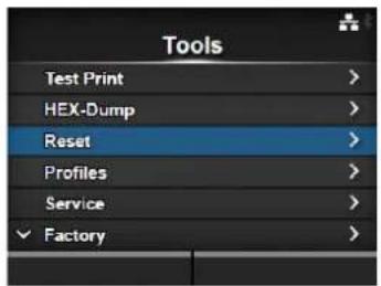
Select
Tools > Reset > Select
Select the items to be initialized.
The items are as follows:
1 Data Initialize the data saved in the printer.
2 Data & Settings Initialize the data and setting values of the printer.
3 Settings Initialize the setting values of the printer.
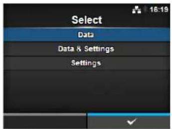
Data
Tools > Reset > Select > Data
Initialize the data saved in the printer.
The data to be initialized are the fonts and graphics registered in the printer.
When you select Data, the confirmation screen shows.
Press the left soft button to cancel or right soft button to perform the initialization.
The printer will reboot after reset.
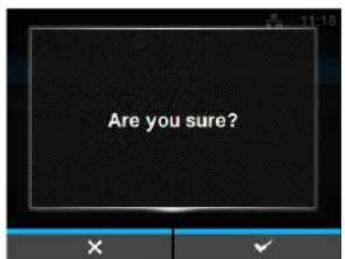
CAUTION
It is generally not necessary to perform the initialization. Doing so could change the print conditions.
Data & Settings
Tools > Reset > Select > Data & Settings
Initialize the data and setting values of the printer.
Select the setting items to be initialized.
The options are as follows:
- User Reset: Initialize the data and setting values.
- User Reset (-Interface): Initialize the data and setting values that are not included in the Interface menu.
- Factory Reset: Initialize to the status after factory shipment.
- Factory Reset (-Interface): Initialize the items that are not included in the Interface menu to the status after factory shipment.
- Interface: Initialize the data and setting values in the Interface menu.
- Printing: Initialize the data and setting values in the Printing menu.
Select the item to be initialized using the ▲buttons, then press the right soft button to perform the initialization.
The confirmation screen shows.
Press the left soft button to cancel or right soft button to perform the initialization.
The printer will reboot after reset.
Refer to Section 7.1 List of Initial Values for the initial value of each setting items.
Note
The data to be initialized are the fonts and graphics registered in the printer.
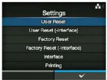
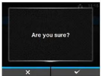
Settings
Tools > Reset > Select > Settings
Select the setting items to be initialized.
The options are as follows:
- User Reset: Initialize the setting values.
- User Reset (-Interface): Initialize the setting values that are not included in the Interface menu.
- Factory Reset: Initialize to the status after factory shipment.
- Factory Reset (-Interface): Initialize the items that are not included in the Interface menu to the status after factory shipment.
- Interface: Initialize the setting values in the Interface menu.
- Printing: Initialize the setting values in the Printing menu.
Select the item to be initialized using the ▲buttons, then press the right soft button to perform the initialization.
The confirmation screen shows.
Press the left soft button to cancel or right soft button to perform the initialization.
Refer to Section 7.1 List of Initial Values for the initial value of each setting item.

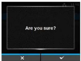
Profiles
Tools > Profiles
Maintain the customized profile of the printer configurations.
The name of the last loaded profile is shown in the parenthesis.
The setting items are as follows:
| 1 Delete Delete the profile of the printer. | |
| *Not available if no profile is saved. | |
| 2 Load Load the profile of the printer. | |
| *Not available if no profile is saved. | |
| 3 Save Save the current printer configurations as a new profile. | |
| 4 Start with Select the profile to load at printer startup. | |
| *Not available if no profile is saved. | |
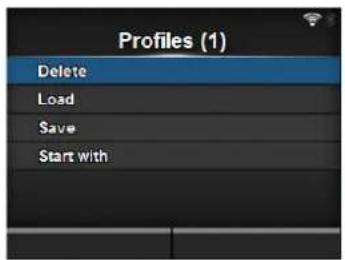
Delete
Tools > Profiles > Delete
Delete the profile of the printer.
The procedure to delete the profile is as follows:
- Select the profile to be deleted using the
buttons. - Press the ← button or press the right soft button to confirm. The profile name is deleted from the list.

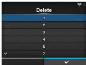
Load
Tools > Profiles > Load
Load the profile of the printer.
The procedure to load the profile is as follows:
- Select the profile to be loaded using the
buttons. - Press the ← button or press the right soft button to confirm. A checkmark shows on the right side of the loaded profile name. And the name of the loaded profile is shown on the Profiles menu in parenthesis.

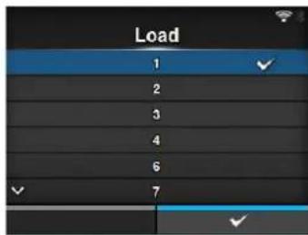
Save
Tools > Profiles > Save
Save the current printer configurations as a new profile.
The screen shows a list of the profiles saved in the printer. If no profile is saved, the screen shows an empty list.
To save existing printer configurations as a new profile, press the left soft button and enter the name of the profile.
You can enter a maximum of thirty-two characters including alphabet (upper case and lower case), numbers and symbols.
Press the right soft button to confirm.
The new profile name is shown on the list and is loaded.
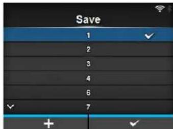
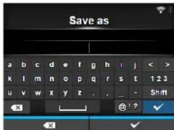
Start with
Tools > Profiles > Start with
Select the profile to be loaded at printer startup.
The procedure to load the profile at printer startup is as follows:
- Select the profile to be loaded at printer startup using the buttons.
- Press the
button or press the right soft button to confirm.


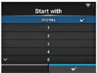
Certificates
Tools > Certificates
Install certificates used for Wi-Fi authentication and for HTTPS. Available only if you have installed the USB memory. The setting items are as follows:
| 1 HTTPS Installs the HTTPS certificates from the USB memory. | ||
| 2 Wi | -Fi Root CA Installs the Wi-Fi Root CA certificates from the USB memory. | |
| 3 | Wi-Fi Client | Installs the Wi-Fi client certificates from the USB memory. |
| 4 Wi | -Fi Private Key Installs the Wi-Fi private key from the USB memory. | |
| 5 EAP-FAST PAC File | Installs the EAP-FAST PAC file from the USB memory. | |
The procedure to install the certificates and PAC files is as follows:
-
Save the certificate files to the USB thumb drive memory's root folder. Acceptable file extensions are:
.pem, .crt, .cer, .der for Root CA and client certificate in PEM or DER format.
.pfx and .p12 for client certificates in PKCS #12 format.
.prv and .key for private keys in PEM/PKCS#8 format.
.pac for PAC files. -
Insert the USB thumb drive memory into the USB connector (Type A).
-
Go to the Settings > Tools > Certificates menu.
-
Select the certificate you want to install. Refer to the table above.
-
Select the certificate file from the list.
CAUTION
Be sure to perform a virus check for the USB memory before connecting it to the printer. SATO Corporation shall not be held responsible for a malfunction of the printer caused by a virus infection through the USB memory.
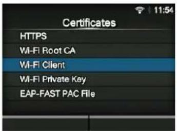
| Barcode Reader | |||
| Tools > Barcode ReaderSet the barcode check function.By connecting a barcode verifier to the USB connector (Type A) of the printer, you can verify the barcodes after printing.The setting items are as follows: |  | ||
| 1 Reading Set up the barcode verifier.*Available only if you have connected the barcode verifier. | |||
| 2 Checking Set the barcode de check function. | |||
| NoteIt is recommended to use the print mode other than tear-off mode with this function.A bracket should be used to ensure proper alignment and highest readability.The barcode check function supports the following code formats. Check the specification of the barcode verifier to ensure compatibility with the available code types. | |||
| Code type Available code format | |||
| 1D Barcodes CODABAR(NW-7)CODE39, CODE93, CODE128JAN/EAN-13/8UPC-A/UPC-EITFIndustrial 2 of 5Matrix 2 of 5MSIGS1-128POSTNETIMB (USPS)GS1 DataBar TruncatedGS1 DataBar StackedGS1 DataBar ExpandedGS1 DataBar Expanded StackedGS1 DataBar Limited | |||
| 2D Codes PDF417Micro PDF417Maxi CodeQR CodeMicro QR CodeData MatrixAztec Code | |||
| Reading | |||
| Tools > Barcode Reader > ReadingSet up the barcode verifier.Available only if you have connected the barcode verifier.The setting items are as follows: |  | ||
| 1 Reader Select Shows the barcode verifier connected to the printer. | |||
| 2 Reader Test Perform a test read with the connected barcode verifier. | |||
| Reader Test | |
| Tools > Barcode Reader > Reading > Reader TestPerform a test read with the connected barcode verifier.Available only if you have connected the barcode verifier.Press the right soft button to start a test read, and check the test result displayed on the screen. |  |
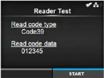 | |
| Checking | |||
| Tools > Barcode Reader > CheckingSet the barcode check function.The setting items are as follows: | 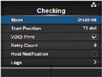 | ||
| 1 Mode Select the check | mode or disable the barcode check function. | ||
| 2 Start Position Adjust the | reading start position. | ||
| 3 VOID Print Enable the | printer to print error marks on the media when a barcode error is detected. | ||
| 4 Retry Count Set how m | any times the printer will try to print the same barcode after a barcode error is detected.*Shows only if you have selected Enabled in the VOID Print menu. | ||
| 5 Host Notification Set wh | ether to return the barcode check results to the host. | ||
| 6 Logs Manage the barcode | check log file saved in the printer. | ||
| Mode | |
| Tools > Barcode Reader > Checking > ModeSelect the check mode or disable the barcode check function.The options are as follows:Disabled: Disable the barcode check function.Readable: Check if the printed barcodes are readable.Comparison: Check if the read results of the printed barcodes match the command data sent from the host. | 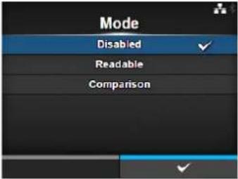 |
Start Position
Tools > Barcode Reader > Checking > Start Position
Adjust the reading start position.
The barcode verifier starts reading each media after the specified length passes from the printing start position.
This setting can be used to exclude first barcode(s) from the check target when multiple barcodes are printed on each media.
The setting range varies depending on the print resolution of the printer. The setting range is as follows:
• 203 dpi: 10 to 20000 dots
• 305 dpi: 15 to 18000 dots
• 609 dpi: 30 to 9600 dots
• 203 dpi: 10 to 20000 dots
• 305 dpi: 15 to 18000 dots
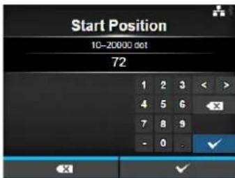
VOID Print
Tools > Barcode Reader > Checking > VOID Print
Enable the printer to print error marks on the media when a barcode error is detected.
This function is to prevent the distribution of defective media with a barcode error.
The options are as follows:
- Enabled: Error marks are printed on the media when a barcode error is detected.
- Disabled: Do not print error marks on the media when a barcode error is detected.
Note
Printing of the VOID mark is not supported in dispenser and linerless (CL4NX only) modes.
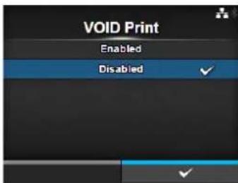
Retry Count
Tools > Barcode Reader > Checking > Retry Count
Set how many times the printer will try to print the same barcode after a barcode error is detected.
Shows only if you have selected Enabled in the VOID Print menu.
The setting range is from 0 to 10.
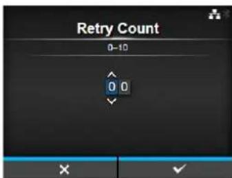
Host Notification
Tools > Barcode Reader > Checking > Host Notification
Set whether to return the barcode check results to the host. The options are as follows:
- Enabled: Return the barcode check results to the host.
- Disabled: Do not return the barcode check results to the host.
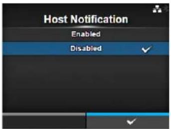
Logs
Tools > Barcode Reader > Checking > Logs
Manage the barcode check logs saved in the printer.
Available only if there are barcode check logs in the printer.
The log includes the operation date and time, the number of read barcodes, barcode data and their check results.
Note that new logs are overwritten on older logs when the log file reaches its maximum size (1MByte).
The setting items are as follows:
| 1 Copy Copy the barcode | check log file to the USB memory.*Available only if you have installed the USB memory. |
2 Remove Remove the barcode check logs.
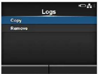
Copy
Tools > Barcode Reader > Checking > Logs > Copy
Copy the barcode check log file to the USB memory.
Available only if you have installed the USB memory.
Press the right soft button to copy the log file to the USB memory.
CAUTION
Be sure to perform a virus check for the USB memory before connecting it to the printer. SATO Corporation shall not be held responsible for a malfunction of the printer caused by a virus infection through the USB memory.
Remove
Tools > Barcode Reader > Checking > Logs > Remove
Delete the barcode check log file.
Press the right soft button to delete the log file.
Clone
Tools > Clone
Copy the current printer settings and installed data to the USB memory. Available only if you have installed the USB memory.
Use the clone configuration when the printer will be replaced with a new printer, or when you set up multiple printers with same settings.
The options are as follows:
- Normal: Copy the printer settings and data excluding LAN/Wi-Fi settings to the USB memory. It is useful when you set up multiple printers already configured for network with same printer settings.
- Normal (+LAN/Wi-Fi): Copy the printer settings and data including LAN/Wi-Fi settings to the USB memory. It is useful when you take over the settings of the printer to be replaced to a new printer.
CAUTION
Be sure to perform a virus check for the USB memory before connecting it to the printer. SATO Corporation shall not be held responsible for a malfunction of the printer caused by a virus infection through the USB memory.
Startup Guide
Tools > Startup Guide
Enable or disable the startup guide.
The options are as follows:
- Enabled: Enable the startup guide.
• Disabled: Disable the startup guide.
If you have selected Enabled in the Startup Guide menu, the startup guide shows the next time you power on the printer.
4.4.7 Information Menu
In the Information menu, there are setting items as follows:
| Information | |||
| 1 Help Shows the guidance video. | 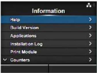 | ||
| 2 Build Version Shows the firmware version. | |||
| 3 Applications Shows various application versions. | |||
| 4 Installation Log Shows the installation log data.*Shows only if there is a log data in the printer. | |||
| 5 Print Module Shows the print module information. | |||
| 6 Counters Shows the counter information. | |||
| 7 IPv4 Address Shows the IPv4 address. | |||
| 8 IPv6 Address Shows the IPv6 address. | |||
| 9 LAN MAC Shows the MAC address of the LAN.*Shows only if the LAN interface is selected. | |||
| 10 Wi-Fi MAC Shows the MAC address of the wireless LAN.*Shows only if the optional wireless LAN is installed and the Wi-Fi interface is selected. | |||
| 11 Wi-Fi Region Shows the region information of the wireless LAN.*Shows only if the optional wireless LAN is installed and the Wi-Fi interface is selected. | |||
| 12 Wi-Fi Status Shows the status of the wireless LAN.*Shows only if the optional wireless LAN is installed and the Wi-Fi interface is selected. | |||
| 13 Wi-Fi Direct Shows the connection information of Wi-Fi Direct.*Shows only if connected using Wi-Fi Direct. | |||
| 14 Wi-Fi Versions Shows the version of the wireless LAN.*Shows only if the optional wireless LAN is installed and the Wi-Fi interface is selected. | |||
Help
Information> Help
Shows the guidance video.
You can view the video for loading the media and ribbon, the cleaning method and replacement method of consumables. For the video list and playback method, refer to Section 4.1.4 Guidance Video.
The list of videos are as follows:
1 Install Paper Shows the video for loading the media.
2 Install Ribbon Shows the video for loading the ribbon.
3 Replace Paper Shows the video for replacing the media.
4 Replace Ribbon Shows the video for replacing the ribbon.
5 Replace Head Shows the video for replacing the print head.
6 Replace Platen Shows the video for replacing the platen roller.
7 Cleaning Shows the video of the cleaning method.
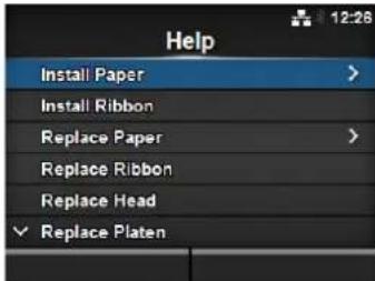
Install Paper
Information > Help > Install Paper
Shows the video for loading the media.
The setting items are as follows:
1 Roll Shows the video for loading the media roll.
2 Fanfold Shows the video for loading the fan-fold media.
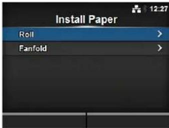
| Roll | |||
| Information > Help > Install Paper > RollShows the video for loading the media roll.The setting items are as follows: | 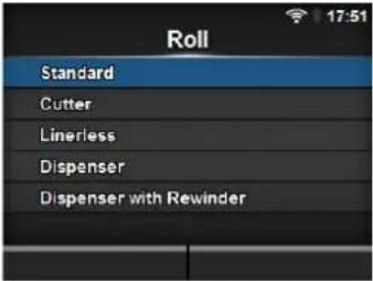 | ||
| 1 Standard | Shows the video | for loading the media roll to a standard printer. | |
| 2 Cutter | Shows the video | ||
| 3 Linerless (CL4NX only) | Shows the video for loading the media roll to a printer installed with a linerless kit. | ||
| 4 Dispenser | Shows the video | for loading the media roll to a printer installed with a dispenser. | |
| 5 Dispenser with Rewinder | Shows the video for loading the media roll to a printer installed with a dispenser and liner rewinder. | ||
| Fanfold | |||
| Information > Help > Install Paper > FanfoldShows the video for loading the fan-fold media.The setting items are as follows: | 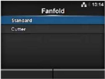 | ||
| 1 Standard Shows the video | for loading the fan-fold mediato a standard printer. | ||
| 2 Cutter Shows the video | |||
| Replace Paper | |||
| Information > Help > Replace PaperShows the video for replacing the media.The setting items are as follows: | 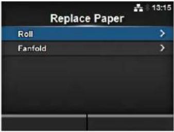 | ||
| 1 Roll | Shows the video for replacing the media roll. | ||
| 2 Fanfold | Shows the video for replacing the fan-fold media. | ||
| Roll | |||
| Information > Help > Replace Paper > RollShows the video for replacing the media roll.The setting items are as follows: | 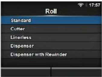 | ||
| 1 Standard | Shows the video | for replacing the media roll in a standard printer. | |
| 2 Cutter | Shows the video | ||
| 3 Linerless (CL4NX only) | Shows the video for replacing the media roll to a printer installed with a linerless kit. | ||
| 4 Dispenser | Shows the video | for replacing the media roll in a printer installed with a dispenser. | |
| 5 Dispenser with Rewinder | Shows the video for replacing the media roll in a printer installed with a dispenser and liner rewinder. | ||
| Fanfold | |||
| Information > Help > Replace Paper > FanfoldShows the video for replacement of fan-fold media.The setting items are as follows: | 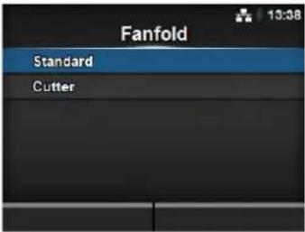 | ||
| 1 Standard Shows the video | for replacing the fan-foldmedia in a standard printer. | ||
| 2 Cutter Shows the video | for replacing the fan-foldmedia in a printer installed with a cutter. | ||
| Build Version | |||
| Information > Build VersionShows the information and version of this printer. | 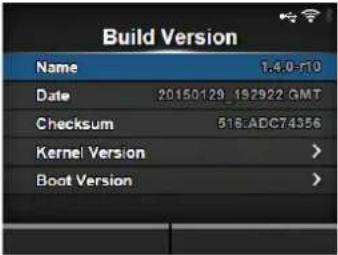 | ||
| 1 Name Shows the name of the build version. | |||
| 2 Date Shows the build date. | |||
| 3 Checksum Shows the checksum of the build version. | |||
| 4 Kernel Version Shows the kernel version. | |||
| 5 Boot Version Shows the boot version. | |||
Kernel Version
Information > Build Version > Kernel Version
Shows the kernel version of this printer.
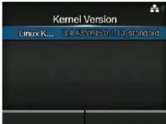
Boot Version
Information > Build Version > Boot Version
Shows the boot version of this printer.
The setting items are as follows:
1 Disks Shows the Disks.
2 Warp!!-mode A checked
3 Date Shows the build date of the boot version.
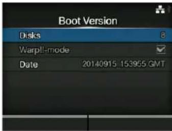
Applications
Information > Applications
Shows the versions of the installed applications in the printer, such as printer languages.
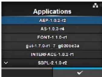
Installation Log
Information > Installation Log
Show or clear the installation log data in this printer. The setting items are as follows:
| 1 RPM Log Shows the RPM log data. |
| 2 System Restore Shows the system restore log data. |
Press CLEAR to clear the selected log data.
Note
This screen is not shown if there is no log data in the printer.
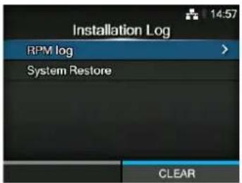
RPM Log
Information > Installation Log > RPM Log
Shows a list of RPM log files containing three sections: installed, updated and obsolete.
The RPM log file is created after installing a pkg-file containing rpm-files.
Press the right soft button to clear the selected RPM log file.
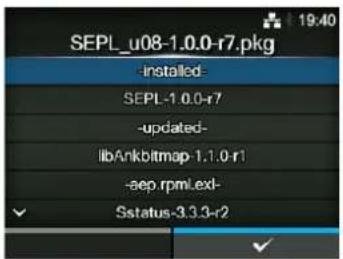
System Restore
Information > Installation Log > System Restore
Shows the system restore log.
The system restore log file is created after installing a pkg-file that incurs the inability to operate the printer LCD.
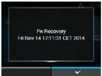
| Print Module | |||
| Information > Print ModuleShows the information about the print module of this printer.The setting items are as follows: | 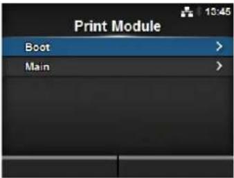 | ||
| 1 Boot Shows the Boot firmware version. | |||
| 2 Main Shows the Main firmware version. | |||
| Boot | |||
| Information > Print Module > Boot | 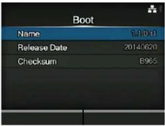 | ||
| 1 Name Shows the Boot firmware version. | |||
| 2 Release Date Shows the Boot firmware release date. | |||
| 3 Checksum Shows the Boot firmware checksum. | |||
| Main | |||
| Information > Print Module > Main | 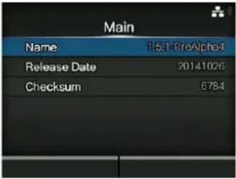 | ||
| 1 Name Shows the Main firmware version. | |||
| 2 Release Date Shows the Main firmware release date. | |||
| 3 Checksum Shows the Main firmware checksum. | |||
| Counters | |||
| Information > CountersShows the counter information of this printer.The setting items are as follows: | 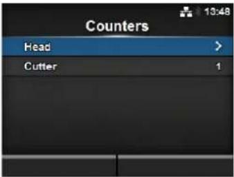 | ||
| 1 Head | Shows the head | counter information of this printer. | |
| 2 Cutter | Shows the current | number of cuts. | |
| CAUTIONOnly SATO authorized service personnel are permitted to clear the counter. | |||
| Head | |||
| Information > Counters > HeadShows the head counter information of this printer. | 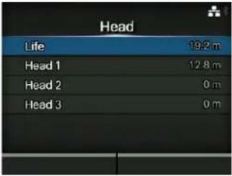 | ||
| 1 Life | Shows the current print distance. | ||
| 2 Head | 1 Head 1 shows the current print distance. When you replace the print head and the counter is cleared, the value of Head 2 is shown in Head 3 and the value of Head 1 is shown in Head 2. Head 1 will start to count from 0 again. | ||
| 3 Head | 2 | ||
| 4 Head | 3 | ||
| IPv4 Address | |
| Information > IPv4 AddressShows the IPv4 address. | 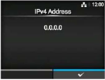 |
IPv6 Address
Information > IPv6 Address
Shows the IPv6 address.
Note
When Wi-Fi Direct is active, this IPv6 address screen is not shown.
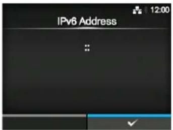
LAN MAC
Information > LAN MAC
Shows the MAC address of the LAN.
Shows only if LAN is the active interface.
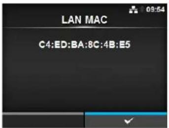
Wi-Fi MAC
Information > Wi-Fi MAC
Shows the MAC address of the wireless LAN.
Shows only if you have installed the optional wireless LAN and Wi-Fi is the active interface.
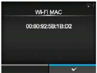
Wi-Fi Region
Information > Wi-Fi Region
Shows the region information of the wireless LAN.
Shows only if you have installed the optional wireless LAN and Wi-Fi is the active interface.
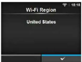
Wi-Fi Status
Information > Wi-Fi Status
Shows the status of the wireless LAN.
Shows only if you have installed the optional wireless LAN and Wi-Fi is the active interface.
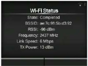
Wi-Fi Direct
Information > Wi-Fi Direct
Shows the connection information of Wi-Fi Direct.
Shows only if Wi-Fi Direct is the active interface and you are connected using Wi-Fi Direct.
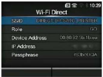
Wi-Fi Versions
Information > Wi-Fi Versions
Shows the version of the wireless LAN.
Shows only if you have installed the optional wireless LAN.
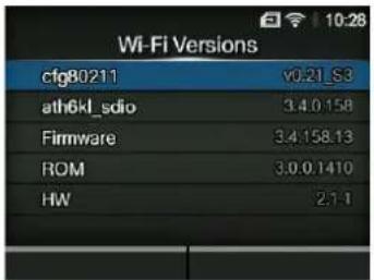
4.5 Web Configuration
The printer can be operated through a web configuration page using any browser.
With an Ethernet LAN or WLAN connection, users can remotely get information from the printer or perform the printer configuration.
You need the printer IP address to access the web configuration page. Refer to Section 4.4.7 Information Menu for the printer IP address.
If the printer IP address is 192.168.143.123, open up browser and enter the following URL:
https://192.168.143.123
When a security certificate is prompted, you must acknowledge and click Continue.
The web configuration page will be shown as follows.
On the upper right of each page, the model name, current resolution and MAC address are shown.
4.5.1 Dashboard
The Dashboard, which consists of smaller sections, is the default page of WebConfig. Each section shows specific information or status of the printer.
You can view Dashboard and Certificates pages without logging in.
However, login is required to view Settings and Tools pages.
Printer Status shows the current state (online, offline error) and current status icons.
Printing shows the print speed, darkness, sensor, print mode and backfeed setting.
Device shows the model, current resolution and options that are installed.
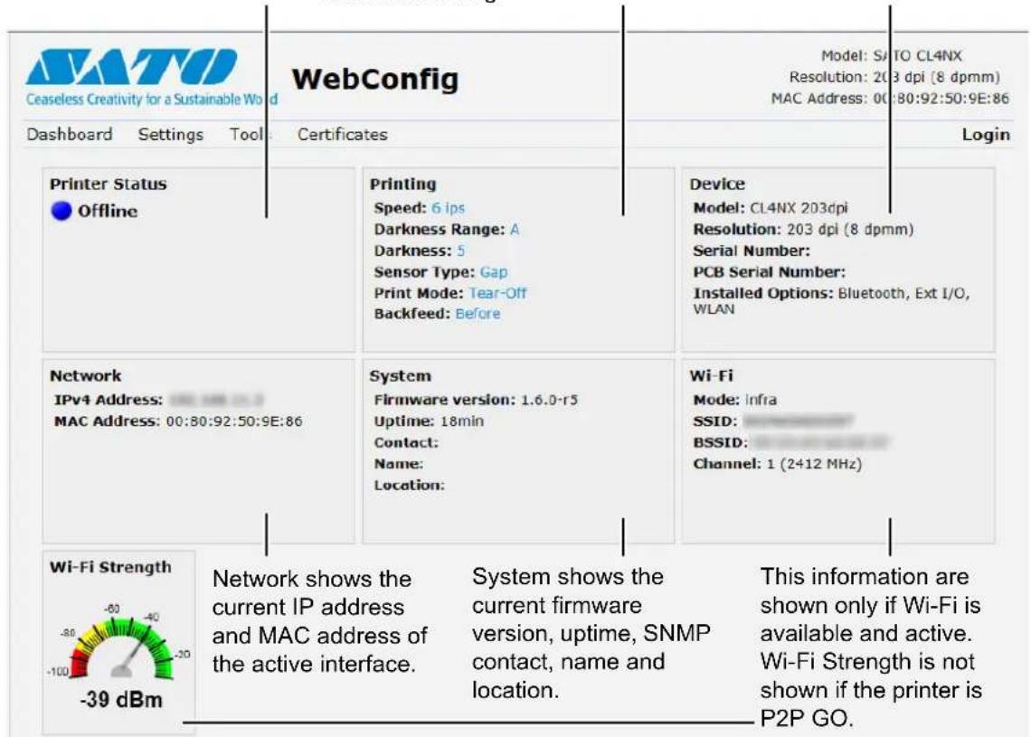
4.5.2 Settings
Login is required to view this page. Click Login and then enter the correct password to log in. The default password for the username settings is 0310.
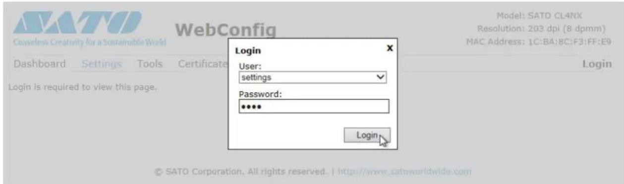
After logging in, the following page will be shown:
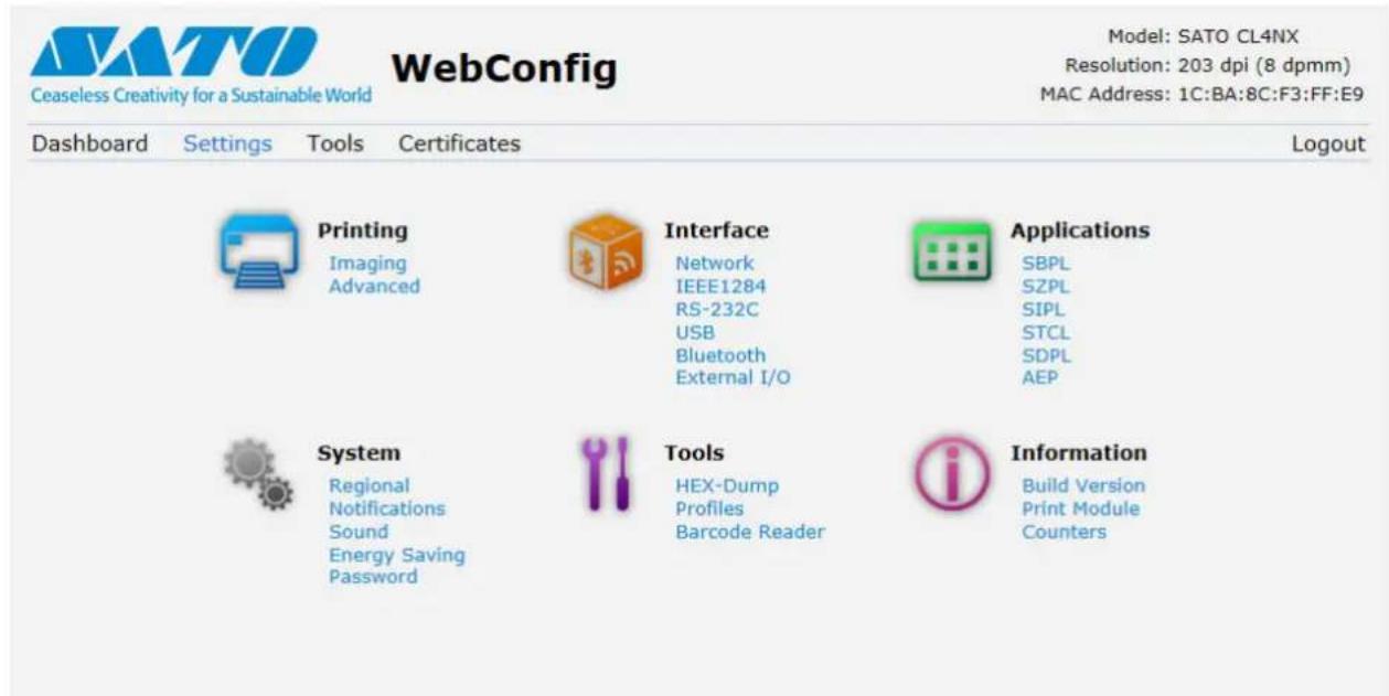
These six setting items are also available on the printer through the LCD screens. For details, refer to Section 4.4 Details of the Settings Menu Screen.
Click on any icon on this Settings page to perform the settings.
The following page will be shown after clicking on Printing:
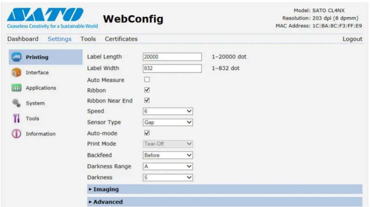
Printing
Refer to Section 4.4.2 Printing Menu.
Interface
Refer to Section 4.4.3 Interface Menu.
Applications
Refer to Section 4.4.4 Applications Menu.
System
Refer to Section 4.4.5 System Menu.
Tools
Refer to Section 4.4.6 Tools Menu.
Information
Refer to Section 4.4.7 Information Menu.
4.5.3 Tools
Login is required to view this page. Click Login and then enter the correct password to log in as in Section 4.5.2 Settings.
The default password for the username settings is 0310.
After logging in, the following page will be shown:
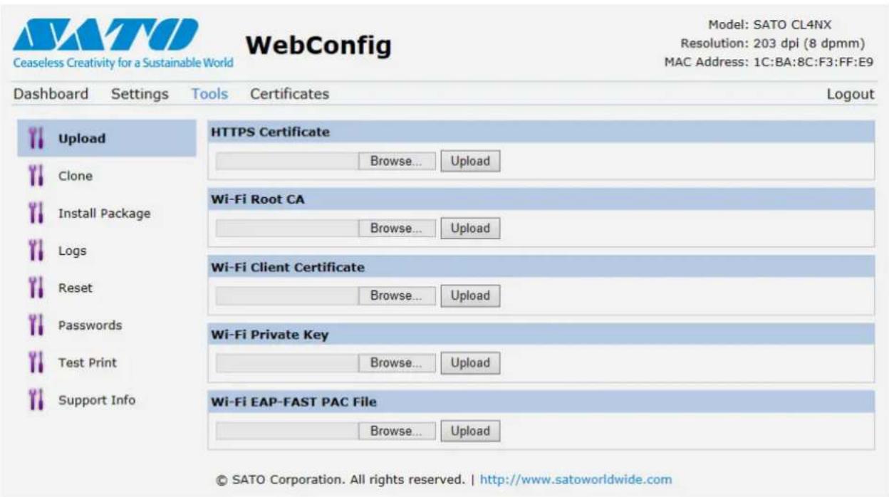
Upload
Refer to Certificates on page 213.
Clone
Refer to Clone on page 219.
Install Package
Refer to Section 2.5 Downloading Firmware of the CL4NX/CL6NX service manual.
Logs
Lists all log files in the log directory. Users can click to download the file.
Reset
Refer to Select on page 209.
Passwords
Refer to Change Password on page 197.
Test Print
Refer to Test Print on page 199.
Support Info
List various information of the printer such as attached options, serial number, application versions and settings configuration. You can also get a screenshot of the current printer display.
4.5.4 Certificates
Shows the Root Certificate authority and client certificates installed on the printer.
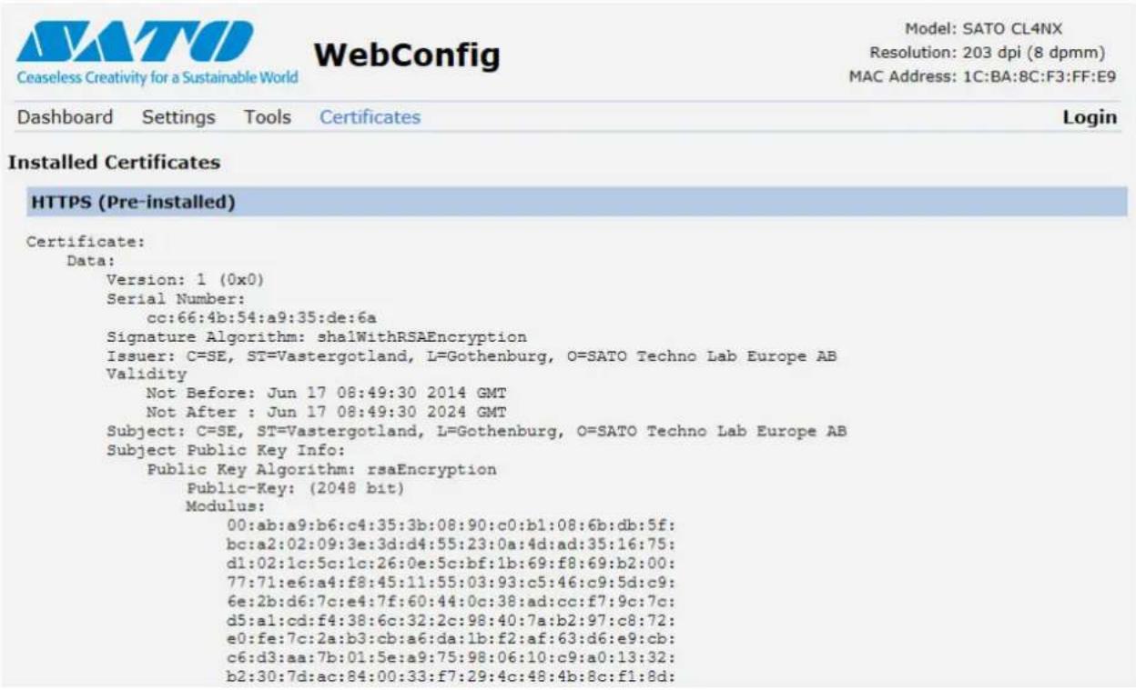
Note
The client certificate that is a PFX (PKCS #12) file will not be shown.
This page is intentionally left blank.
5
Cleaning and Performing Printer Adjustments
5.1 Maintenance
A dirty print head or platen roller not only affects the print quality but also causes errors. Use a cleaning kit or cleaning sheet to clean the printer regularly.

CAUTION
- Do not touch the power button, connect or disconnect the power cord while your hands are wet. Doing so could cause an electric shock.
- Disconnect the power cord from the AC outlet before you begin cleaning.
The print head and its surroundings are hot after printing. Wait until the printer cools down. - Touching the edge of the print head with your bare hand could cause injury.
- Be careful not to touch the cutter blade when cleaning the printer.
- Use a cleaning pen, cotton swab or cotton cloth from a cleaning kit to clean. Do not clean with a hard object. Doing so could cause damage.
- Remove the media and ribbon before cleaning.

CAUTION for CL4NX only (if installed with linerless kit)
- Open the print head if the printer is not used for printing for more than one day. Paper jam might occur the next time when you print if the print head is closed for a long period with linerless label loaded.
- When loading linerless label, make sure that the front end of the media extends about 3 cm (1.18") out the media discharge outlet.
Note
You can purchase a cleaning kit or cleaning sheet from a SATO reseller or technical service center.
5.2 Maintenance of the Print Head and Platen Roller
Maintenance should be performed at the following regular intervals:
• After you print one media roll or print media for one hundred and fifty meters.
Use the cleaning kit to clean these parts:
- Print head • Platen roller
• Media sensors • Media guide
• After you print six media rolls or print media for nine hundred meters.
Use the cleaning sheet to clean these parts:
- Print head • Platen roller
Use the cleaning kit to clean these parts:
• Media route • Ribbon route
Maintenance intervals for the optional linerless kit (CL4NX only):
- After you print one media roll or whenever there is any glue residue or paper dust on the media route. Use the cleaning kit to clean these parts:
- Print head • Media guide
• Media sensors • Guide rollers
* There is no need of cleaning the linerless platen roller unless it is significantly soiled.
Note
The above maintenance intervals are only for reference. Perform the cleaning when necessary.
5.2.1 Maintenance using the Cleaning Kit
The maintenance procedure using the cleaning kit is as follows:

CAUTION
Never use organic solvents, such as thinner and benzine to clean the printer.
Note
For details on the cleaning kit, refer to the manual attached to the cleaning kit.
1 Make sure that the printer is in power off mode, then disconnect the power cord from the AC outlet.
2 Open the top cover.

CAUTION
Open the top cover fully to prevent accidental drop of the cover.
3
Push the head lock lever ① towards the rear to unlock the print head.

CAUTION
- The print head and its surroundings are hot after printing. Be careful not to touch it, to avoid being burned.
- Touching the edge of the print head with your bare hand could cause injury.
4
Remove the media and ribbon if they are already loaded.
Refer to Section 3.3 Removing the Ribbon and the reverse procedure in Section 3.5 Loading Media.
5
Clean the dirt on the print head ②, platen roller ③ and ribbon roller ④ using a cleaning pen or a cotton swab dabbed with cleaning liquid.

natural_image
Technical line drawing of a mechanical device with internal components and mounting bracket (no text or symbols)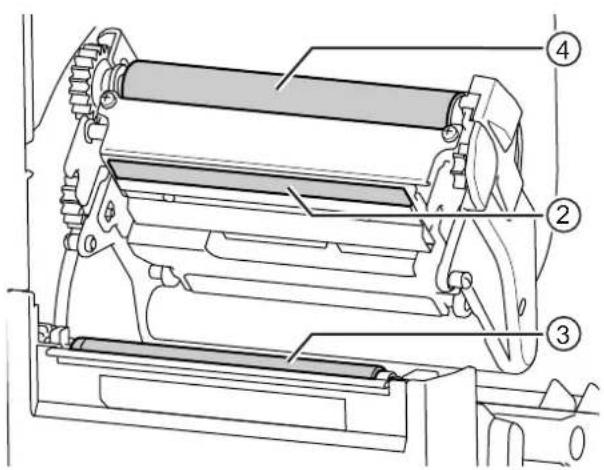
6 Tilt the sensor guide lock ⑤ down and pull out the media sensor guide ⑥.
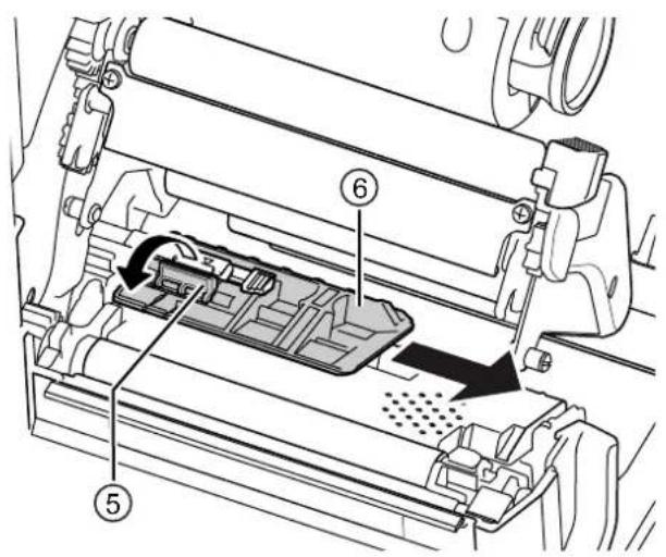
7 Clean the bottom of the media sensor guide using the cotton cloth dabbed with cleaning liquid.
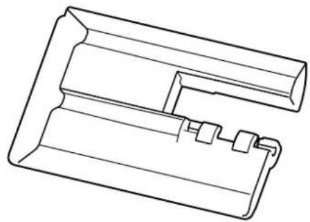
natural_image
Technical line drawing of a mechanical component with no visible text or symbols8 Clean the media sensor ⑦ using the cotton cloth dabbed with cleaning liquid.
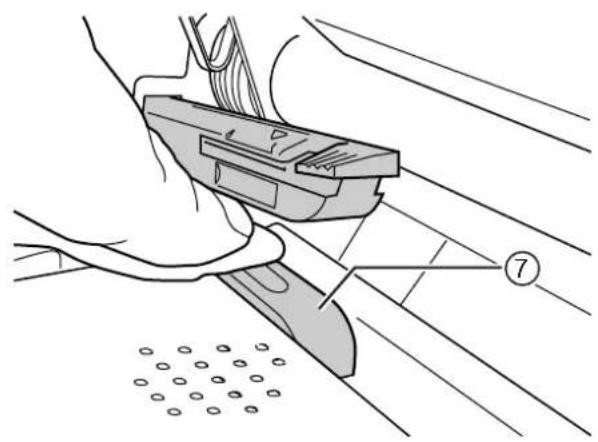
natural_image
Technical illustration of a hand operating a mechanical device with a numbered label (7) and circular components below, no readable text or symbols present.9 Return the media sensor guide to its original position and tilt the sensor guide lock up to the locked position.
5.2.2 Additional Procedure for the Optional Linerless Kit (CL4NX only)
1 After performing step 8 above, clean the media guide ⑧ and inner surface ⑨ that is in contact to the label edge. Use the cotton cloth dabbed with cleaning liquid to clean.
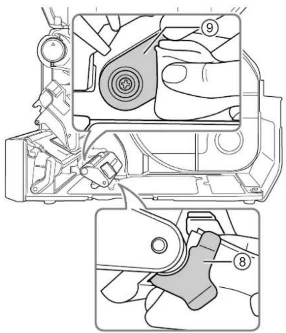
2 Clean the guide rollers ^10 using the cotton cloth dabbed with cleaning liquid. Rotate the guide rollers to clean the whole areas of them.
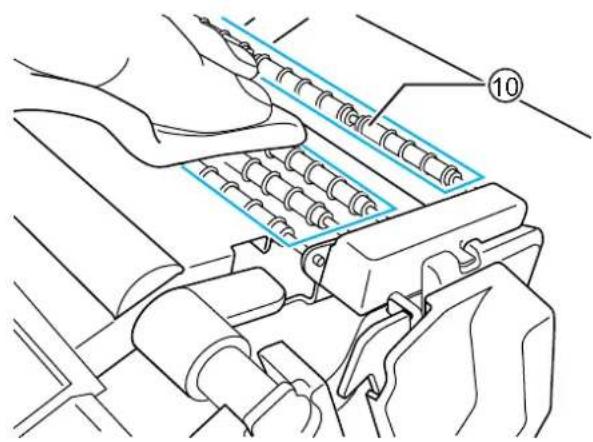
5.2.3 Maintenance using the Cleaning Sheet
The maintenance procedure using the cleaning sheet is as follows:
1 Make sure that the printer is in power off mode, then disconnect the power cord from the AC outlet.
2 Open the top cover.

CAUTION
Open the top cover fully to prevent accidental drop of the cover.
3 Push the head lock lever ① towards the rear to unlock the print head.

CAUTION
• The print head and its surroundings are hot after printing. Be careful not to touch it, to avoid being burned.
- Touching the edge of the print head with your bare hand could cause injury.
4 Remove the media and ribbon if they are already loaded.
natural_image
Technical line drawing of a mechanical device with internal components and mounting bracket (no text or symbols)Refer to Section 3.3 Removing the Ribbon and the reverse procedure in Section 3.5 Loading Media.
5 Place the cleaning sheet ② between the print head and the platen roller.
Note
Align the rough side of the cleaning sheet adjacent to the print head.
natural_image
Technical line drawing of a mechanical device with internal components and labeled parts (no text or symbols)6 Press the print head down until you lock the head lock lever in place.
7 Using two hands, pull the cleaning sheet away from the printer.
8 After you pull out the cleaning sheet, repeat steps 5 through 7, two or three more times.
When no more dirt appears on the cleaning sheet after you have pulled it out, stop repeating these steps.
9 Push the head lock lever ① towards the rear to unlock the print head.
10 Use a cleaning pen ③ to clean the dirt on the print head.
natural_image
Technical line drawing of a mechanical device with a downward arrow indicating a component (no text or symbols present)
natural_image
Line drawing of hands operating a mechanical device with rollers and a flat panel (no text or symbols)
5.3 Adjusting the Base Reference Point
5.3.1 About the Base Reference Point
The base reference point is the point at which one determines the print position and stop/cut/dispensing position.
The base reference point differs depending on the operation mode or media sensor you use.
5.3.2 Adjusting the Print Position
Set the Pitch in the Printing > Advanced > Adjustments menu to adjust the print position.
Note
The above base reference point (print position) will be the stop position when the sensor type is set to Gap sensor.
Adjust the print position using the following procedure:
1 When the printer is in online mode, press the ▶ button on the operator panel to change to offline mode.
2 Press the ← button to show the Settings menu.
3 Select Printing using the ◀/▶ buttons, then press the ◀button.
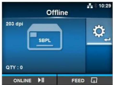
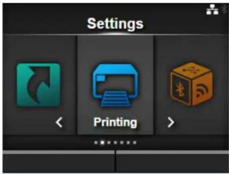
4 Select Advanced > Adjustments > Pitch using the ▲ buttons, then press the ◀ button.
The Pitch screen shows.
5 Change the setting value. Press the ◀/▶/▲/▼ button to set and then press the ◀ button to enter the number to the text box.
The setting range is as follows:
203 dpi: -30 to +30 dots
305 dpi: -45 to +45 dots
609 dpi: -90 to +90 dots
203 dpi: -30 to +30 dots
305 dpi: -45 to +45 dots
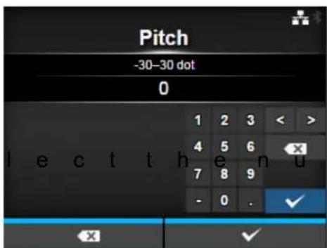
6 Press the right soft button to save the setting value.
7 Press the ▶ button to change to offline mode.
8 Press the button again to change to online mode.
You can perform printing to check the adjusted print position.
5.3.3 Adjusting the Media Stop Position
Set the Offset in the Printing > Advanced > Adjustments menu to adjust the media stop position.
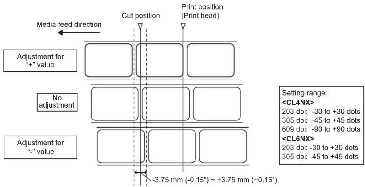
Note
- The above cut reference position for printing indicates the label stop position when the media sensor is set to Gap sensor.
- You can also adjust when the operation mode is specified to Tear-off or Dispenser.
Adjust the stop position using the following procedure:
1 When the printer is in online mode, press the ▶button on the operator panel to change to offline mode.
2 Press the ← button to show the Settings menu.

3 Select Printing using the ◀/▶ buttons, then press the ◀button.
4 Select Advanced > Adjustments > Offset using the ▲ buttons and the ← button.
The Offset screen shows.
5 Change the setting value. Press the ◀/▶/▲/▼ button to set and then press the ◀ button to enter the number to the text box.
The setting range is as follows:
203 dpi: -30 to +30 dots
305 dpi: -45 to +45 dots
609 dpi: -90 to +90 dots
203 dpi: -30 to +30 dots
305 dpi: -45 to +45 dots
6 Press the right soft button to save the setting value.
7 Press the ▶ button to change to offline mode.
8 Press the ▶ button again to change to online mode.
You can perform printing to check the adjusted stop position.
5.3.4 Notes on the Stop/Cut Position of Different Media
Stop position of the label in dispenser mode.
The regular position is to let the label stay about 2 ± 1 mm ( 0.08'' ± 0.04'' ) on the liner.
Cut position when using the label in cutter mode.
The regular cut position is between labels (only cut on the liner).
Do not cut on the label as the remaining adhesive on the blade will decrease the performance of the cutter.
Cut position when using the media with perforated line in cutter mode.
Do not cut on the perforated line or area from the perforated line towards you. Doing so may cause a paper jam or damage.
• Media roll
Do not cut on the perforated line or within 1 mm (0.04") from the perforated line towards you.
- Fan-fold media
Do not cut on the perforated line or within 4 mm to 25 mm (0.16" to 0.98") from the perforated line towards you.
flowchart
graph TD
    A["Media Feed Direction"] --> B["Cut Position (I-mark Sensor)"]
    A --> C["Cut Position (Gap Sensor)"]
    D["✓"] --> E["Label"]
    F["×"] --> G["Label"]
    H["Liner"] --> I["Label"]
    J["Cut Position"] --> K["Label"]
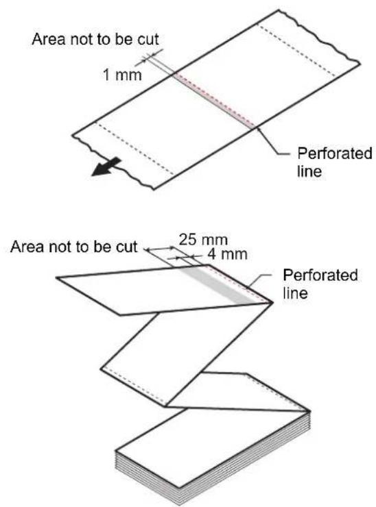
5.4 Adjusting the Print Quality
You can adjust the print quality by adjusting the print darkness and print speed.
5.4.1 Adjustment of the Print Darkness
The adjustment procedure for the print darkness is as follows:
Note
- You can fine tune the print darkness by setting the Darkness Adjust in the Printing > Advanced > Adjustments menu.
- When Prioritize in the Printing > Advanced menu has been set to Commands, the data will be printed with the print darkness specified by command.
• To adjust the print darkness while pausing the print job, refer to Section 4.1.5 How to Adjust the Print Settings During Printing.
1 When the printer is in online mode, press the ▶ button to change the printer to offline mode.
2 Press the ← button to show the Settings menu.
3 Press the ◀buttons to select Printing and then press the ◀button.
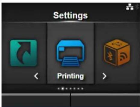
4 Press the ▲ buttons to select Darkness and then press the ← button. The Darkness screen shows.
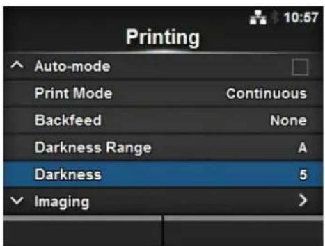
5 Press the ▲buttons to select a value.
The setting range is from 1 to 10. 1 is the lightest and 10 is the darkest.
6 Press the right soft button or ◁ button to save the value.
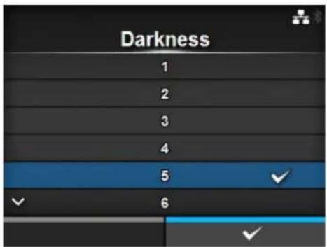
7 Press the ▶ button to change to offline mode.
8 Press the button again to change to online mode.
You can perform printing to check the print quality.
5.4.2 Adjusting the Print Speed
The adjustment of the print speed not only changes the speed of printing but also affects the print quality. The setting range of the print speed varies depending on the following print resolution:
• Resolution 203 dpi (8 dots/mm): 2 to 10 (inches/sec)
• Resolution 305 dpi (12 dots/mm): 2 to 8 (inches/sec)
• Resolution 609 dpi (24 dots/mm): 2 to 6 (inches/sec)
- Resolution 203 dpi (8 dots/mm): 2 to 10 (inches/sec)
• Resolution 305 dpi (12 dots/mm): 2 to 8 (inches/sec)
Note
- When Prioritize in the Printing > Advanced menu has been set to Commands, the data will be printed with the print speed specified by command.
- To adjust the print speed while pausing the print job, refer to Section 4.1.5 How to Adjust the Print Settings During Printing.
Note (CL4NX only)
If the optional linerless kit is installed, the setting range will be from 2 to 6 ips (inches/sec) regardless of the print resolution of the printer.
The adjustment procedure for the print speed is as follows:
1 When the printer is in online mode, press the ▶button to change the printer to offline mode.
2 Press the ← button to show the Settings menu.
3 Press the ◀buttons to select Printing and then press the ◀button.
4 Press the ▲/▼ buttons to select Speed and then press the ◀button.
The Speed screen shows.
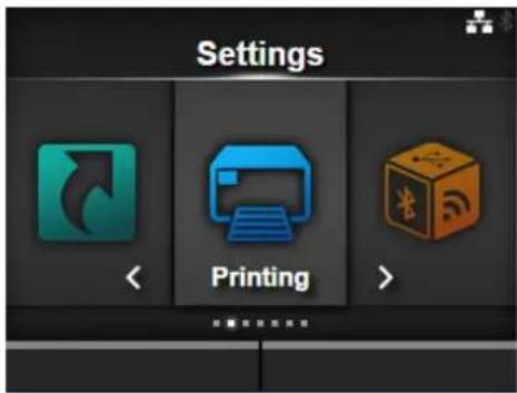
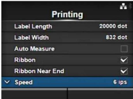
5 Press the ▲buttons to select a value.
6 Press the right soft button or button to save the value.
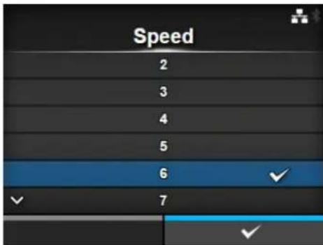
7 Press the ▶ button to change to offline mode.
8 Press the ▶ button again to change to online mode.
You can perform printing to check the print quality.
5.5 Adjusting the Buzzer Volume
The adjustment procedure for the buzzer volume when an error occurs is as follows:
1 When the printer is in online mode, press the ▶ button on the operator panel to change to offline mode.
2 Press the ← button to show the Settings menu.
3 Press the ◀/▶ buttons to select System and then press the ◀ button.
4 Select Sound > Error Sound using the ▲/▼buttons and then press the ← button.
The Error Sound screen shows.
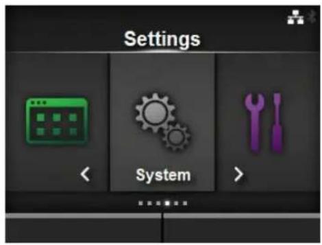
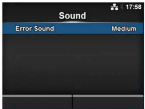
5 Press the ▲buttons to set the volume.
The options are as follows:
- Off: Mute the sound.
- Low: Low volume.
• Medium: Medium volume.
• High: High volume.
6 Press the right soft button or ◀ button to save the setting.
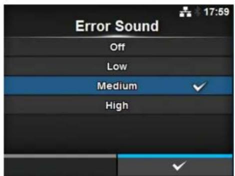
5.6 Adjusting the Head Pressure Balance
Print head balance refers to the equalization of pressure between the print head and the platen roller. If the print head balance is out of adjustment, the printed image will be darker on one side of the media than the other and the media will be prone to travel in the direction of greater pressure.
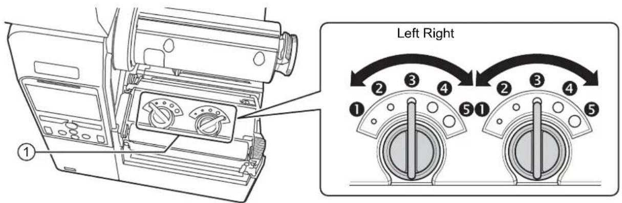
Setting the Criteria of the Head Pressure Balance
- Set the head pressure according to the media thickness, including the liner.
- Set the pressure balance according to the media width.
5.6.1 Head Pressure Setting
The adjustment procedure for the head pressure is as follows:
1 Open the top cover of the printer.
2 Find the adjustment dials ① on the top of the print head assembly as shown.
3 Turn the adjustment dials ① to match the media thickness.
| Media Thickness (mm) | CL4NX: 0.080-0.200CL6NX: 0.060-0.200 | 0.200 - 0.268 |
| Adjustment dials | 3 (Left and Right, CL4NX only)3 to 4 (Left and Right, CL6NX only) | 4 to 5 (Left and Right) |
| Reference | Thin paper/normal label, etc. Thick paper/tag, etc. | |
4 Be sure to perform the pressure balance setting as explained below, after step 3.
Note
• The factory default setting is Left ③ and Right ③.
For CL6NX dispenser model, the factory default setting is Left ④ and Right ④.
• The thickness of the media includes the liner.
5.6.2 Pressure Balance Setting
The adjustment procedure for the pressure balance is as follows:
1 Open the top cover of the printer.
2 Find the adjustment dials ① on the top of the print head assembly as shown.
3 Turn the adjustment dials ① according to the media width and set the pressure balance.
For CL4NX:
| Media Width (mm) | 25 - 54 54 - 83 83 | - 131 | |
| Adjustment dials | Left 3Right 1 | Left 3Right 2 | Left 3Right 3 |
*First use the dial setting for the head pressure and then adjust according to the media width. Above table shows an example when the head pressure is Left ③.
For CL6NX:
| Media Width (mm) | 50 - 120 120 - 1 | 40 140 - 160 160 - 180 | |
| Adjustment dials | Left 5Right 1 | Left 3 or 4Right 1 | Left 3 or 4Right 2 |
*First use the dial setting for the head pressure and then adjust according to the media width.
Note
The factory default setting is Left ③ and Right ③.
For CL6NX dispenser model, the factory default setting is Left ④ and Right ④.
This page is intentionally left blank.
6
Troubleshooting
This chapter explains the errors that can occur on the printer and the displays for indicating the current status.
6.1 When an Error Message Occurs
When there is an error on the printer, the error message will show on the screen.
The error message, its cause and the countermeasures are as follows:
| Error | ||||
| No. | Message Cause Countermeasure | |||
| 1001 | Machine error | Defective circuit board. Replace | the main board. | |
 | To clear the error: Power off the printer. | |||
| 1003 | Parity error | RS-232C settings are incorrect. | Adjust the interface settings correctly. | |
 | To clear the error: Press the Offline or ▶Button, or adjust the settings. | The cable connection is incorrect. | Check and connect the cable correctly. | |
| 1004 | Overrun error | RS-232C settings are incorrect. | Adjust the interface settings correctly. | |
 | To clear the error: Press the Offline or ▶Button, or adjust the settings. | The cable connection is incorrect. | Check and connect the cable correctly. | |
| 1005 | Framing error | RS-232C settings are incorrect. | Adjust the interface settings correctly. | |
 | To clear the error: Press the Offline or ▶Button, or adjust the settings. | The cable connection is incorrect. | Check and connect the cable correctly. | |
| 1006 | Buffer overflow | The size of the received data exceeds the size of the receive buffer. | Do not send data that exceeds the size of the receive buffer. | |
 | To clear the error: Press the Offline or ▶ button. | The communication settings between the printer and the host are incorrect. | Set the communication between the printer and the host correctly. | |
| Error | |||||
| No. | Message Cause Countermeasure | ||||
| 1007 | Head open | The print head is unlocked. Lock | the print head. | ||
 | To clear the error:Close the printhead. | The sensor for sensing theopen/close status of the printhead is defective. | Replace the sensor forsensing the open/close statusof the print head. | ||
| 1008 | Out of paper | The media is not loaded. Load themedia correctly. | |||
 | To clear the error:Load the mediaand open/closethe print head orpress the Offlineor ▶■ button. | The media is not loadedcorrectly. | |||
| The sensitivity of the mediasensor is not set correctly. | Adjust the sensor level. | ||||
| The media has jammed. Remove the jammed media. | |||||
| The media sensor is dirty. Clean the media sensor. | |||||
| The cable of the media sensoris disconnected. | Connect the cable of themedia sensor correctly. | ||||
| 1009 | End of ribbon | The ribbon is not loaded. Load a new ribbon. | |||
 | To clear the error:Load the ribboncorrectly andclose the printhead or press theOffline or ▶■button. | The ribbon is damaged. | |||
| The ribbon is not loadedcorrectly. | Load the ribbon correctly. | ||||
| 1010 | Media error | The configured media sizeand loaded media size aredifferent. | Check the configured mediasize and loaded media size. | ||
 | To clear the error:Press the Offlineor ▶■utton oropen/close theprint head. | The received print data islarger than the configuredmedia size. | Check the print data. | ||
| The media is fed a longerdistance due to the incorrectsensor level. | Adjust the sensor level. | ||||
| 1012 | Print head error | The print elements are wornout. | Change print head checkconditions to only check formissing elements in barcodesand try to adjust missingelements to white bars. | ||
 | To clear the error:Power off orchange the headcheck conditions. | ||||
| The print head is damaged. Replace the print head. | |||||
| 1013 | USB write error To clear the error: Insert USB memory, remove USB memory or press the Offline or ▶ button. To clear the error: Insert USB memory, remove USB memory or press the Offline or ▶ button. | The USB memory is disconnected while writing. | Connect the USB memory. | ||
| The copy area in the USB memory is not sufficient. | Make sure that the USB memory has sufficient copy area. | ||||
| Writing to the USB memory fails. | Replace the USB memory. | ||||
| The USB memory is not formatted. | Format the USB memory. | ||||
| 1014 | USB memory full To clear the error: Use USB memory with sufficient space or press the Offline or ▶ button. To clear the error: Use USB memory with sufficient space or press the Offline or ▶ button. | The space in the USB memory is not sufficient. | Delete unwanted data from the USB memory. | ||
| 1015 | Cutter error To clear the error: Press the FEED button. To clear the error: Press the FEED button. | A media jam has occurred in the cutter unit. | Remove the jammed media from the cutter unit. | ||
| The cutter blade does not return to the specified position. | Press the FEED button to move the cutter blade back to the specified position. | ||||
| 1016 | Cutter open To clear the error: Close the bracket of the cutter. To clear the error: Close the bracket of the cutter. | The cutter-open lever is open. | Close and lock the cutter-open lever. | ||
| The cable of the cutter unit is disconnected. | Connect the cable of the cutter unit correctly. | ||||
| The cutter open sensor is defective. | Replace the cutter open sensor. | ||||
| 1017 | Command error To clear the error: Press the Cancel or ▶ button. To clear the error: Press the Cancel or ▶ button. | Incorrect command or parameter in the print data.Caaa: position of error occurrence: error command name cc: error code | Check the print data. | ||
| 1018 | RFID tag error (CL4NX only) To clear the error: Press the Cancel button. To clear the error: Press the Cancel button. | Could not read/write to the RFID inlay. | Discard this tag. | ||
| 1019 | RFID system error (CL4NX only) | RFID module is not operating correctly. | Contact the technical support center for repair of the RFID module. | ||
 | To clear the error: Power off the printer. | ||||
| 1020 | Calendar error | The date and time of the calendar are incorrect. | Check if you have installed the RTC kit or replace the RTC PCB. | ||
 | To clear the error: Change the calendar setting, press the Offline or Button, or power off the printer. | ||||
| 1021 | BCC check error | The BCC code of the data to be sent (one item) is incorrect. | Check the data to be sent and communication settings. ▶ button: Continue printing from the print data where the BCC error occurred. Send the SUB command: Clear the BCC error and continue printing from where it stopped. | ||
 | To clear the error: Press the ▶ button or cancel the print job. | ||||
| 1022 | Overheat error | The temperature of the printer has exceeded its tolerance value. | Stop the operation of the printer to let the temperature decrease. | ||
 | To clear the error: Stop the operation of the printer and wait until the temperature decreases. | ||||
| 1023 | NTP error | Could not connect to the time server and set the calendar clock. | Confirm that the address of the time server is correct. Confirm that there is a connection to the time server. If RTC kit is installed, the calendar can be set manually and operation resumed without NTP functionality. To check or set the clock, go to the System settings menu and set the Date and Time. | ||
 | To clear the error: Press the Offline button or change the calendar setting. | ||||
| 1024 | Head density changed | The print head is not installed. | Install the print head. | ||
 | To clear the error: Confirm the prompted message. | A new print head with a different resolution has been installed. | Install a print head with the same density as the old print head. | ||
| 1028 | Gap not found | Meandering media. Clean and adjust the media path. | |||
 | To clear the error: Press the Offline button or open/ close the print head. | The sensor type is incorrect. Use the correct sensor type. | |||
| The media sensor level is incorrect. | Adjust the media sensor level. | ||||
| 1035 | I-mark not found | Meandering media. Clean and adjust the media path. | |||
 | To clear the error: Press the Offline button or open/ close the print head. | The sensor type is incorrect. Use the correct sensor type. | |||
| The media sensor level is incorrect. | Adjust the media sensor level. | ||||
| 1046 | EAP authentication error (EAP failure) | EAP Authentication failure. Use the correct Wi-Fi settings. | |||
 | To clear the error: Change the Wi-Fi settings or press the Offline button. | ||||
| 1047 | EAP authentication error (EAP timeout) | EAP Authentication failure. Use | the correct Access Point (AP) and authentication server settings. | ||
 | To clear the error:Press the Offline button. | ||||
| 1050 | Bluetooth error | Bluetooth module is defective. | Contact the technical support center for repair of the Bluetooth module. | ||
 | To clear the error:Confirm the prompted message. | ||||
| 1058 | CRC check error | CRC has not been added to the data.CRC does not match. | Check transmitted data and interface settings.Right soft button: Continue printing from the print data where the CRC error occurred.Left soft button: Cancel the print data with the CRC error and continue printing from the next item. | ||
 | To clear the error:Press the left or right soft button. | ||||
| 1066 | Paper jam error (CL4NX only) | The media has jammed. Remove | the jammed media.Load the media again. | ||
 | To clear the error:Open the print head and load the media again. | ||||
| 1073 | Non-RFID warning (CL4NX only) | With Non-RFID warning enabled and RFID tag loaded, the items received do not contain an RFID issue command. | Add an RFID issue command to the print job.Disable Non-RFID warning.Replace with non-RFID label. | ||
 | To clear the error:Press the Cancel button. | ||||
| 1077 | Barcode reader connection error | The barcode verifier is not detected at printer startup when the barcode checking mode is enabled. | Check and connect the barcode verifier correctly. | ||
 | To clear the error:Press the Offline button. | ||||
| Error | |||
| No. | Message Cause Countermeasure | ||
| 1078 | Barcode reading error To clear the error:Press the Offlineor Cancel button. To clear the error:Press the Offlineor Cancel button. | Could not read the barcodenormally. | Check the position of thebarcode verifier and settings. |
| 1079 | Barcode reading error To clear the error:Press the Offlinebutton. To clear the error:Press the Offlinebutton. | A value larger than the loadedmedia length is specified forchecking start position. | Set a value smaller than theloaded media length forchecking start position. |
| 1080 | Barcode comparison error To clear the error:Press the Offlineor Cancel button. To clear the error:Press the Offlineor Cancel button. | The read result of the barcodedoes not match the commanddata. | Check the layout for printingand barcode verifier settings. |
6.1.1 More Information about Command Error
Printer motion when detecting a command error
When Show Error is set to ENABLE in Applications >SBPL, the command error information is shown on the error message (second line), and the print operation is paused.
This error can be cleared by pressing the left soft button CANCEL X, but the data in which an error is detected is discarded and cannot be printed.
Location of error occurrence
"Caaa" in the command error message shows the location of command error.
The number of ESC commands from ESC+A is shown in "aaa".
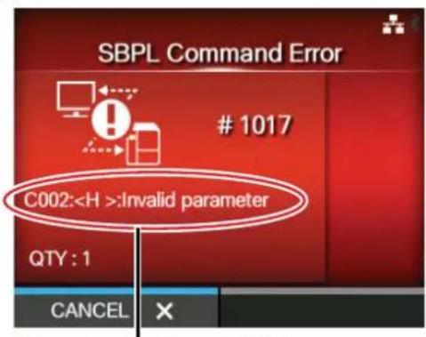
Command error information
Note that the ESC+A command is not included in the number of ESC commands, which can be shown up to 999. If the number of ESC commands exceeds 999, it is shown as "999".
Example)
When a command error is detected by the Horizontal Print Position
----: [ESC]A
C001: [ESC]V100
C002: [ESC]H99999 => Location of the command error
C003: [ESC]L0202
C004: [ESC]M, ABCDEF
C005: [ESC]Q1
C006: [ESC]Z
In this case, C002 is the location of the error.
Error command name
The command name, in which an error is detected, is shown in "
* A one-byte command name is left aligned.
Error description
The cause of command error will be shown in "cc" in the error message ("Caaa:
| Description (“cc”) Cause | |
| Invalid command Analyzed | improper command. |
| Invalid parameter Received | improper parameter. |
| Command table read error | Failed to read the command table. |
| Invalid graphic data/custom designed data | Analyzed improper graphic and external character data. |
| Invalid registration area Specified memory area (card slot) is inappropriate.Tried to write to a write-protected media. | |
| This number is already registered | Number specified by registration command has already been taken. |
| Over registration area limit Exceeded the registration area. (Memory full). | |
| Description (“cc”) Cause | |
| Data is not registered Data is not registered. | |
| Printing position is out of printable area | The specified print start position is outside the printable area. |
| Barcode image is out of printable area | The printing image is outside the printable area. (Barcode only). |
6.2 When the LED Lights Red/Blue
The LED will light or flash to show the current status of the printer.
The status when the LED lights or flashes is as follows:
| LED Printer Status | Countermeasure | |
| Light off. The power | is off or the printer is in offline mode. | Power on the printer or change it to online mode. |
| Lights blue. The printer | is in online mode. You can operate the printer. | |
| Flashes blue.(At intervals of 2 seconds) | The printer is in sleep mode. You can operate the printer. | |
| Lights red. An error has occurred. Clear the error according to the message. | ||
Note
If the printer enters sleep mode during a printer error status (LED lights red), the LED indicator will flash blue at intervals of two seconds.
6.3 Troubleshooting Table
Check the items below when the printer does not operate correctly.

WARNING
- Do not touch the power button, connect or disconnect the power cord while your hands are wet. Doing so could cause an electric shock.
- Disconnect the power cord from the AC outlet before you perform the cleaning.
Note
You can purchase a cleaning kit or cleaning sheet from a SATO reseller or technical service center.
6.3.1 No Power/Nothing on the Screen
| No. | What to check Countermeasure | |
| 1 Is | the power cord fully connected to the AC outlet? | Connect the power cord to the AC outlet fully. |
| 2 Is | the power cord fully connected to the printer? Connect the power cord to the AC input terminal of the printer fully. | |
| 3 Is | the power cord damaged? Replace the power cord. | Contact a SATO reseller or technical service center for the specific power cord for this printer.Do not use power cords that are not designed specifically for this printer. |
| 4 Is | there electricity at the AC outlet that supplies the power to the printer? | Check if there is electricity at the AC outlet.Connect to another AC outlet. |
6.3.2 Cannot Feed the Media
| No. | What to check Countermeasure | |
| 1 | Are the media and ribbon designed for the printer? | Use media and ribbon designed for the printer. |
| 2 | Are the media and ribbon loaded correctly? Load the media and ribbon correctly. | media and ribbon correctly. |
| 3 | Is the media or ribbon deformed? Use the media or ribbon that is not deformed.You cannot feed the media or ribbon that is deformed. | You cannot feed the media or ribbon that is deformed. |
| 4 | Is the media guide set correctly? Adjust the media guide. | Adjust the sensor level. |
| 5 | Is the correct sensor type set? Set the correct sensor type. | |
| 6 | Is the sensitivity of the sensor set correctly? | |
| 7 | Is the platen roller dirty? | If the platen roller is dirty, clean it with the cleaning kit.For printer cleaning, refer toSection 5.2Maintenance of the Print Head and Platen Roller. |
| 8 Is | the platen roller damaged? Replace the platen roller. | |
| 9 Does the interface operate correctly? Check the interface according to the Interface Troubleshooting. | ||
| 10 Is | the data or signal sent from the computer incorrect? | Power on the device again.Check the data sent from the computer and communication conditions. |
| 11 Is | the main board defective? Replace the main board. | |
6.3.3 Can Feed the Media but Cannot Print
| No. | What to check Countermeasure | |
| 1 | Are the media and ribbon designed for use with the printer? | Use the media and ribbon designed for the printer. |
| 2 | the ribbon wound correctly. If the knob of the ribbon | rewinder is not set to its initial position, remove the wound ribbon then set the knob again. |
| 3 | the correct sensor type set? Set a correct sensor type. | |
| 4 | the print head installed correctly? Install the print head correctly. | |
| 5 | the pressure of the print head too strong or too weak? | Adjust the pressure of the print head with the head pressure adjustment dial. |
| 6 | the print head dirty or is there a label attached to it? | If the print head is dirty, clean it using the cleaning pen. If a label is attached to the print head, remove it.If the glue of label is attached to the print head, clean it using a cleaning kit.Do not clean using a hard object. Doing so could cause damage to the print head.For printer cleaning, refer to Section 5.2 Maintenance of the Print Head and Platen Roller. |
| 7 | the media sensor dirty? If the media sensor is dirty, | clean it using the cleaning kit.For printer cleaning, refer to Section 5.2 Maintenance of the Print Head and Platen Roller. |
| 8 | Does the interface operate correctly? Check the interface according to the Interface Troubleshooting. | |
| 9 | the data or signal sent from the computer incorrect? | Power on the device again.Check the data sent from the computer and communication conditions. |
| 10 Is | the print head defective? Replace the print head and reset the counter. | |
| 11 Is | the main board defective? Replace the main board. |
6.3.4 Bad Print Quality
| No. | What to check Countermeasure | |
| 1 | Are the media and ribbon designed for use with the printer? | Use media and ribbon designed for the printer. |
| 2 | Are the media and ribbon loaded correctly? Check if the media and ribbon are loaded correctly. | |
| 3 | Is the tension of the ribbon correct? Adjust the tension of the ribbon. | |
| 4 | Is the print head installed correctly? Install the print head correctly. | |
| 5 | Is the pressure of the print head too strong or too weak? | Adjust the pressure of the print head with the head pressure adjustment dial. |
| 6 | Is the print speed too fast? Adjust the print speed. | |
| 7 | Is the print darkness too low or too high? Adjust the print darkness. | |
| 8 | Is the platen roller dirty? | If the platen roller is dirty, clean it using the cleaning kit.For printer cleaning, refer to Maintenance. |
| 9 | Is the print head dirty or is there a label attached to it? | If the print head is dirty, clean it using the cleaning pen. If a label is attached to the print head, remove it.If the glue of label is attached to the print head, clean it using a cleaning kit.Do not clean using a hard object. Doing so could cause damage to the print head.For printer cleaning, refer to Section 5.2Maintenance of the Print Head and Platen Roller. |
| 10 | Is the print head defective? Replace the print head and reset the counter. | |
| 11 | Is the platen roller damaged? Replace the platen roller. | |
| 12 | Is the main board defective? Replace the main board. |
6.3.5 Incorrect Print Position
| No. | What to check Countermeasure | |
| 1 | Are the media and ribbon designed for use with the printer? | Use media and ribbon designed for the printer. |
| 2 | Are the media and ribbon loaded correctly? Check if the media and ribbon are loaded correctly. | |
| 3 | Is the media or ribbon deformed? Use the media or ribbon that is not deformed.You cannot feed the media or ribbon that is deformed. | |
| 4 | Is the print head installed correctly? Adjust the print head. | |
| 5 | Is the media guide set correctly? Adjust the media guide. | |
| 6 | Is the correct sensor type set? Set the correct sensor type. | |
| 7 | Is the sensitivity of the sensor set correctly? | Adjust the sensor level. |
| 8 | Is the offset set correctly? Adjust the offset. | |
| 9 | Is the pitch offset or base reference point offset set correctly? | Adjust the pitch offset or base reference point offset. |
| 10 | Is the platen roller dirty? | If the platen roller is dirty, clean it using the cleaning kit.For printer cleaning, refer to Section 5.2 Maintenance of the Print Head and Platen Roller. |
| 11 | Is the media sensor dirty? | If the media sensor is dirty, clean it using the cleaning kit.For printer cleaning, refer to Section 5.2 Maintenance of the Print Head and Platen Roller. |
| 12 | Is the data or signal sent from the computer incorrect? | Power on the device again.Check the data sent from the computer and communication conditions. |
| 13 | Is the platen roller damaged? | Replace the platen roller. |
6.4 Interface Troubleshooting
When an interface error occurs on the printer, check with the checklist related to that interface.
6.4.1 USB Interface
| No. Item to check |
| 1 Check that the USB cable is connected correctly. |
| 2 Check that the cable is not damaged. |
| 3 Check the configuration of the printer.Check the setting of the USB interface through the Settings > Interface > USB menu. |
| 4 If there are multiple USB ports on the computer, connect to another port. |
| 5 Disconnect other USB devices from the computer. |
| 6 Power on the printer and computer again. |
| 7 Install the USB driver again. |
6.4.2 LAN Ethernet Interface
| No. | Item to check |
| 1 | Check that the LAN cable is connected correctly. |
| 2 | Check that the cable is not damaged. |
| 3 | Check the configuration of the printer.Check the setting of the LAN Ethernet interface through the Settings > Interface > Network menu. |
| 4 | Check that the allocated IP address is accessible by PING. |
| 5 | Check that the power of the HUB is on. |
| 6 | Check that the HUB is not defective. |
| 7 | Power on the printer again. |
6.4.3 Bluetooth Interface
| No. Item to check | |
| 1 Check that the Bluetooth function is on. | |
| 2 | Check that the devices using the same frequency band, such as wireless LAN enabled devices or microwaves are not in use. |
| 3 Check that there is no obstacle such as a metal rack between the printer and the host. | |
| 4 Check the configuration of the printer.Check the setting of the Bluetooth interface through the Settings > Interface > Bluetooth menu. | |
| 5 Power on the printer and computer again. | |
| 6 Install the Bluetooth driver again. | |
6.4.4 RS-232C Interface
| No. Item to check | |
| 1 Check that the RS-232C cable is connected correctly. | |
| 2 Check that the cable is not damaged. | |
| 3 Check the configuration of the printer.Check the setting of the RS-232C interface through the Settings > Interface > RS-232C menu. | |
| 4 If there are multiple RS-232C ports on the computer, connect to another port. | |
| 5 Power on the printer and computer again. | |
| 6 Check that no other software is using the same RS-232C port. |
6.4.5 IEEE1284 Interface
| No. Item to check | |
| 1 Check that the printer cable is connected to the LPT port of the computer correctly. | |
| 2 Check that the cable is not damaged. | |
| 3 If you are using a Windows printer driver, check that the correct port is selected. | |
| 4 Check the configuration of the printer.Check the setting of the IEEE1284 interface through the Settings > Interface > IEEE1284 menu. | |
| 5 Connect to another port. | |
| 6 Power on the printer again. |
6.4.6 External Signal Interface (EXT)
| No. Item to check | |
| 1 Check that the printer and external device are connected with a cable correctly. | |
| 2 Check that the cable is not damaged. | |
| 3 Check that the power of the external device is on. | |
| 4 Check the configuration of the printer.Check the setting of the external signal (EXT) interface through the Settings > Interface > External I/O menu. | |
| 5 Power on the printer and external device again. |
6.4.7 Wireless LAN Interface
| No. Item to check | |
| 1 Check that the wireless LAN function is on. | |
| 2 | Check that the devices using the same frequency band, such as wireless LAN enabled devices or microwaves are not in use. |
| 3 Check that there is no obstacle such as a metal rack between the printer and the host. | |
| 4 Check the configuration of the printer.Check the setting of the wireless LAN interface through the Settings > Interface > Network > Settings > Wi-Fi menu. | |
| 5 Power on the printer again. | |
This page is intentionally left blank.
7
Appendix
7.1 List of Initial Values
The initial value refers to the setting value of the printer when it was shipped from the factory. If you reset the printer, the setting values of the printer will change back to the factory default values. The tables below show the initial value of each setting item and type of reset that changes the value back to the initial value.

CAUTION
It is generally not necessary to perform the initialization. Doing so will remove all the customer settings.
7.1.1 Printing Menu
| Setting Item Initial Value User | Reset | Factory Reset | ||
| CL4NX CL6NX | ||||
| Label Length 203 dpi: 20000 dots | 305 dpi: 18000 dots609 dpi: 9600 dots | 203 dpi: 20000 dots305 dpi: 18000 dots | Yes Yes | |
| Label Width 203 dpi: 832 dots | 305 dpi: 1248 dots609 dpi: 2496 dots | if Head Base Position is Standard203 dpi: 1216 dots305 dpi: 1984 dots if Head Base Position is Left-justify203 dpi: 1340 dots305 dpi: 2010 dots | Yes Yes | |
| Auto Measure Disable Yes Yes | ||||
| Ribbon Use Ribbon Yes Yes | ||||
| Ribbon Near End | Enable | Yes | Yes | |
| Speed | 203 dpi: 6 ips305 dpi: 6 ips609 dpi: 4 ipsLinerless mode: 4 ips | 203 dpi: 6 ips305 dpi: 6 ips | Yes Yes | |
| Sensor Type | GapNone (When Print Mode is Linerless) | Gap | Yes Yes | |
| Auto-mode | Enabled | Yes Yes | ||
| Setting Item | Initial Value | User Reset | Factory Reset | |
| CL4NX | CL6NX | |||
| Print Mode | Tear-Off (No option is installed)Cutter (If cutter is installed)Dispenser (If dispenser is installed)Linerless (If linerless kit is installed) | Tear-Off (No option is installed)Cutter (If cutter is installed)Dispenser (If dispenser is installed) | Yes Yes | |
| Backfeed | Before (If Print Mode is set to Tear-Off or Linerless)After (If Print Mode is set to Dispenser or Cutter)None (If Print Mode is set to Continuous) | Before (If Print Mode is set to Tear-Off)After (If Print Mode is set to Dispenser or Cutter)None (If Print Mode is set to Continuous) | Yes Yes | |
| Eject Cut 0 s Yes Yes | ||||
| Darkness Range A Yes Yes | ||||
| Darkness 5 Yes Yes | ||||
| Imaging — | — | |||
| Vertical 0 dot Yes Yes | ||||
| Horizontal | 0 dot Yes Yes | |||
| Advanced | — | — | ||
| Calibrate | — | — | ||
| Auto-calibration*1 | Gap + I-Mark | — | — | |
| GAP Levels | Value adjusted by the factory. | No | No | |
| GAP Slice Levels | Auto | No | No | |
| I-Mark Levels | Value adjusted by the factory. | No | No | |
| I-Mark Slice Level | Auto | No | No | |
| Head Check | Off Yes Yes | |||
| Head Check Mode | Always | Yes Yes | ||
| Every Page | 1 Yes Yes | |||
| Check Media Size | Disabled | Yes Yes | ||
| Adjustments | — | — | ||
| Offset | 0 dot No | No | ||
| Pitch | 0 dot No | No | ||
| Darkness Adjust | 50 | No | No | |
| Start Online | Enabled | Yes Yes | ||
*1 Auto-calibration is not available for linerless models.
| Setting Item | Initial Value | User Reset | Factory Reset | |
| CL4NX | CL6NX | |||
| Feed After Error Disabled Yes Yes | ||||
| Feed At Power On Disabled Yes Yes | ||||
| Finisher Feed 0 dot Yes Yes | ||||
| Paper End Using I-mark Yes Yes | ||||
| Head Base Position Standard Yes Yes | ||||
| Prioritize Commands Yes Yes | ||||
| Reprint Disabled Yes Yes | ||||
| Print End Position | 0 dot Yes Yes | |||
| Label Near End | Disabled Yes Yes | |||
7.1.2 Interface Menu
| Setting Item Initial Value User | Reset | Factory Reset | ||
| CL4NX CL6NX | ||||
| Network — | — | |||
| Settings — | — | |||
| LAN — | — | |||
| IPv4 — | — | |||
| Mode DHCP Yes/ | Interface | Yes/Interface | ||
| DHCP — | — | |||
| IP Address 0.0.0.0 | Yes/ | Interface | Yes/Interface | |
| Netmask | 255.255.255.0 | Yes/Interface | Yes/Interface | |
| Gateway | 0.0.0.0 | Yes/Interface | Yes/Interface | |
| DNS | 0.0.0.0 | Yes/Interface | Yes/Interface | |
| IPv6 — | — | |||
| Mode Auto | Yes/ | Interface | Yes/Interface | |
| DHCP — | — | |||
| IP Address :: | Yes/ | Interface | Yes/Interface | |
| Prefix Length | 64 | Yes/Interface | Yes/Interface | |
| Gateway | :: | Yes/Interface | Yes/Interface | |
| DNS | :: | Yes/Interface | Yes/Interface | |
| Proxy | — | — | ||
| Enabled | Disabled | Yes/Interface | Yes/Interface | |
| Server | — | Yes/Interface | Yes/Interface | |
| Exclude | — | Yes/Interface | Yes/Interface | |
| Wi-Fi | — | — | ||
| IPv4 — | — | |||
| Setting Item | Initial Value | User Reset | Factory Reset | |
| CL4NX | CL6NX | |||
| Mode DHCP Yes/ | Interface | Yes/ Interface | ||
| DHCP — | — | |||
| IP Address 0.0.0.0 Yes/ | Interface | Yes/ Interface | ||
| Netmask 255.255.255.0 Yes/ | Interface | Yes/ Interface | ||
| Gateway 0.0.0.0 Yes/ | Interface | Yes/ Interface | ||
| DNS 0.0.0.0 Yes/ | Interface | Yes/ Interface | ||
| IPv6 — | — | |||
| Mode Auto Yes/ | Interface | Yes/ Interface | ||
| DHCP — | — | |||
| IP Address :: Yes/ | Interface | Yes/ Interface | ||
| Prefix Length 64 | Yes/ | Interface | Yes/ Interface | |
| Gateway :: Yes/ | Interface | Yes/ Interface | ||
| DNS :: Yes/ | Interface | Yes/ Interface | ||
| Proxy | — | — | ||
| Enabled | Disabled | Yes/ Interface | Yes/ Interface | |
| Server | — | Yes/ Interface | Yes/ Interface | |
| Exclude | — | Yes/ Interface | Yes/ Interface | |
| Wi-Fi Protected Setup | — | — | ||
| Button (PBC) — | — | |||
| PIN | — | — | ||
| Wi-Fi Direct | — | — | ||
| Device Name | SATO_PRINTER | Yes/ Interface | Yes/ Interface | |
| Connect | — | — | ||
| Start Group | — | — | ||
| Remove Group | — | — | ||
| Setting Item Initial Value | User | Reset | Factory Reset | |
| CL4NX | CL6NX | |||
| Disconnect — | — | |||
| SSID DIRECT-xx-SATO_PRINTER — | — | |||
| IP Address x.x.x.x — | — | |||
| Passphrase xxxxxxx— | — | |||
| SSID SATO_PRINTER Yes/ | Interface | Yes/Interface | ||
| Hidden SSID Enabled | Yes/ | Interface | Yes/Interface | |
| Mode | Ad-hoc | Yes/Interface | Yes/Interface | |
| Channel | 6 | Yes/Interface | Yes/Interface | |
| Security | None | Yes/Interface | Yes/Interface | |
| WEP Conf. | — | — | ||
| Authentication | Open system | Yes/Interface | Yes/Interface | |
| Key Index | 1 | Yes/Interface | Yes/Interface | |
| Key #1 - Key #4 | — | Yes/Interface | Yes/Interface | |
| WPA Conf. | — | — | ||
| WPA Authentication | Personal (PSK) | Yes/Interface | Yes/Interface | |
| PSK | — | Yes/Interface | Yes/Interface | |
| EAP Conf. — | — | |||
| EAP Conf. | — | — | ||
| EAP Mode | FAST | Yes/Interface | Yes/Interface | |
| Inner Method | MSCHAPv2 | Yes/Interface | Yes/Interface | |
| Username | — | Yes/Interface | Yes/Interface | |
| Password | — | Yes/Interface | Yes/Interface | |
| Anon. Outer ID | — | Yes/Interface | Yes/Interface | |
| Verify Server Cert. | Enabled | Yes/Interface | Yes/Interface | |
| Setting Item | Initial Value | User Reset | Factory Reset | |
| CL4NX | CL6NX | |||
| Private Key P/W — Yes/ | Interface | Yes/Interface | ||
| PAC Auto Provisioning Disabled Yes/ | Interface | Yes/Interface | ||
| PAC P/W — Yes/ | Interface | Yes/Interface | ||
| Interface Auto Yes/ | Interface | Yes/Interface | ||
| Services — | — | |||
| Ports — | — | |||
| Port1 1024 Yes/ | Interface | Yes/Interface | ||
| Port2 1025 Yes/ | Interface | Yes/Interface | ||
| Port3 9100 Yes/ | Interface | Yes/Interface | ||
| Flow Control Status4 ENQ | Yes/ | Interface | Yes/Interface | |
| BCC | Disabled Yes/ | Interface | Yes/Interface | |
| NTP | — | — | ||
| Enable | Disabled No Yes | |||
| Error | Disabled No Yes | |||
| Time Server IP | 0.0.0.0 | No | Yes | |
| LPD | Enabled | Yes/Interface | Yes/Interface | |
| FTP | — | — | ||
| Enable | Disabled Yes/ | Interface | Yes/Interface | |
| FTP Timeout | 300 | Yes/Interface | Yes/Interface | |
| SNMP | — | — | ||
| sysContact | — Yes/ | Interface | Yes/Interface | |
| sysName | — Yes/ | Interface | Yes/Interface | |
| sysLocation | — Yes/ | Interface | Yes/Interface | |
| Agent | — | — | ||
| Enable Disabled Yes/ | Interface | Yes/Interface | ||
| Read-Only — | — | |||
| SNMP Version 1|2c|3 Yes/ | Interface | Yes/Interface | ||
| Community public Yes/ | Interface | Yes/Interface | ||
| User rouser Yes/ | Interface | Yes/Interface | ||
| User Security None Yes/ | Interface | Yes/Interface | ||
| Authentication Protocol | MD5 Yes/ | Interface | Yes/Interface | |
| Authentication Passphrase | mypassword | Yes/Interface | Yes/Interface | |
| Privacy Protocol | DES | Yes/Interface | Yes/Interface | |
| Privacy Passphrase | mypassword | Yes/Interface | Yes/Interface | |
| Read-Write | — | — | ||
| SNMP Version 1|2c|3 Yes/ | Interface | Yes/Interface | ||
| Community private | Yes/ | Interface | Yes/Interface | |
| User rwuser | Yes/ | Interface | Yes/Interface | |
| User Security None Yes/ | Interface | Yes/Interface | ||
| Authentication Protocol | MD5 Yes/ | Interface | Yes/Interface | |
| Authentication Passphrase | mypassword | Yes/Interface | Yes/Interface | |
| Privacy Protocol | DES | Yes/Interface | Yes/Interface | |
| Privacy Passphrase | mypassword | Yes/Interface | Yes/Interface | |
| Traps | — | — | — | |
| Enable Disabled Yes/ | Interface | Yes/Interface | ||
| SNMP Version | 1 | Yes/Interface | Yes/Interface | |
| IP Version 4 Yes/ | Interface | Yes/Interface | ||
| Destinations 1 Yes/ | Interface | Yes/Interface | ||
| Destination 1 0.0.0.0 Yes/ | Interface | Yes/Interface | ||
| Destination 2 0.0.0.0 Yes/ | Interface | Yes/Interface | ||
| Destination 3 0.0.0.0 Yes/ | Interface | Yes/Interface | ||
| Community trapcom Yes/ | Interface | Yes/Interface | ||
| User trapuser Yes/ | Interface | Yes/Interface | ||
| Engine ID Number generated from MAC address Yes/ | Interface | Yes/Interface | ||
| Security | None | Yes/Interface | Yes/Interface | |
| Authentication Protocol | MD5 | Yes/Interface | Yes/Interface | |
| Authentication Passphrase | mypassword | Yes/Interface | Yes/Interface | |
| Privacy Protocol | DES | Yes/Interface | Yes/Interface | |
| Privacy Passphrase | mypassword | Yes/Interface | Yes/Interface | |
| Advanced | — | — | — | |
| ARP Announcement | — | — | — | |
| Additional | Enabled Yes/ | Interface | Yes/Interface | |
| Periodic | 0 Yes/ | Interface | Yes/Interface | |
| IEEE1284 | — | — | — | |
| Flow Control | Status4 Multi | Yes/Interface | Yes/Interface | |
| BCC | Disabled | Yes/Interface | Yes/Interface | |
| RS-232C | — | — | — | |
| Baudrate | 115200 | Yes/Interface | Yes/Interface | |
| Parameters 8-N-1 Yes/ | Interface | Yes/Interface | ||
| Flow Control STATUS4 Yes/ | Interface | Yes/Interface | ||
| BCC Disabled Yes/ | Interface | Yes/Interface | ||
| USB — | — | |||
| Flow Control Status4 Yes/ | Interface | Yes/Interface | ||
| BCC Disabled Yes/ | Interface | Yes/Interface | ||
| Bluetooth — | — | |||
| Enable Enabled Yes/ | Interface | Yes/Interface | ||
| Name | SATO PRINTER_xxxxxxxxxxxxx (BD address) | Yes/Interface | Yes/Interface | |
| Pin Code | 0000 | Yes/Interface | Yes/Interface | |
| BD Address | xxxxxxxxxxxx | Yes/Interface | Yes/Interface | |
| Firm Version spp3_vX.YY | Yes/ | Interface | Yes/Interface | |
| Host BD Addr | — | Yes/Interface | Yes/Interface | |
| Authentication | None | Yes/Interface | Yes/Interface | |
| ISI | 2048 | Yes/Interface | Yes/Interface | |
| ISW | 18 | Yes/Interface | Yes/Interface | |
| PSI | 2048 | Yes/Interface | Yes/Interface | |
| PSW | 18 | Yes/Interface | Yes/Interface | |
| CRC Mode | Disabled Yes/ | Interface | Yes/Interface | |
| Flow Control Status4 Multi | Yes/ | Interface | Yes/Interface | |
| Ignore CR/LF | Disabled Yes/ | Interface | Yes/Interface | |
| Ignore CAN/DLE Disabled Yes/ | Interface | Yes/Interface | ||
| External I/O — | — | |||
| Enable Disabled Yes/ | Interface | Yes/Interface | ||
| Signals — | — | |||
| EXT 9PIN MODE1 Yes/ | Interface | Yes/Interface | ||
| EXT Mode TYPE4 Yes/ | Interface | Yes/Interface | ||
| Inputs — | — | |||
| Start Print PIN5 | Yes/ | Interface | Yes/Interface | |
| Reprint | PIN7 | Yes/Interface | Yes/Interface | |
| Outputs | — | — | ||
| Paper End/Paper/Ribbon End (If RFID is installed) | PIN1 | Yes/Interface | Yes/Interface | |
| Ribbon End/RFID Tag Error (If RFID is installed) | PIN3 | Yes/Interface | Yes/Interface | |
| Machine Error/Machine/RFID Error (If RFID is installed) | PIN4 | Yes/Interface | Yes/Interface | |
| Print Done | PIN6 | Yes/Interface | Yes/Interface | |
| Qty/Offline | PIN9 | Yes/Interface | Yes/Interface | |
| Ribbon Near End | PIN10 | Yes/Interface | Yes/Interface | |
| Dispenser | OFF | Yes/Interface | Yes/Interface | |
| Label Near End | OFF | Yes/Interface | Yes/Interface | |
| EXT I/O Re-print | Disabled Yes/ | Interface | Yes/Interface | |
| RFID | — | — | — | — |
| Antenna Pitch | Standard | — | Yes/Interface | Yes/Interface |
| Write Power 10 dBm — Yes/ | Interface | Yes/ Interface | ||
| Read Power 10 dBm — Yes/ | Interface | Yes/ Interface | ||
| Tag Offset 0 mm — Yes/ | Interface | Yes/ Interface | ||
| Reader Model | XXXXXXXXXXXXXXXXXX | — | — | — |
| Reader Version | XXXXXXXXXXXXXXXXXX | — | — | — |
| View — — | — | — | ||
| Memory Bank | EPC (UHF)/USER (HF) | — Yes Yes | ||
| Retry Mode Retry — Yes/ | Interface | Yes/ Interface | ||
| Retries 1 — Yes/ | Interface | Yes/ Interface | ||
| Mark bad tags | Enabled | — | Yes/ Interface | Yes/ Interface |
| MCS | — | — | — | |
| MCS | Disabled | — | Yes/ Interface | Yes/ Interface |
| Chip Manufacturer | IMPINJ | — | Yes | Yes |
| Pre-Encoded Tag | Disabled | — | Yes/ Interface | Yes/ Interface |
| Assign Prefix | Auto | — | Yes/ Interface | Yes/ Interface |
| MCS Prefix Digit | 3 bits — Yes/ | Interface | Yes/ Interface | |
| Input Prefix | 0 | — | Yes/ Interface | Yes/ Interface |
| Non-RFID Warning | Disabled | — | Yes/ Interface | Yes/ Interface |
| Log RFID Data | Disabled | — | Yes/ Interface | Yes/ Interface |
| Data To Record | EPC and TID | — | Yes/ Interface | Yes/ Interface |
| Output Error Mode | Level — Yes/ | Interface | Yes/ Interface | |
| Pulse Length | 100 ms | — | Yes/ Interface | Yes/ Interface |
| Counters | — | — | — | |
| Lifetime | — | — | — | |
| Setting Item Initial Value User | Reset | Factory Reset | ||
| CL4NX | CL6NX | |||
| Count Success 000000 — No Yes | ||||
| Count Failure 000000 — No Yes | ||||
| Count Total 000000 — No Yes | ||||
| User — — | — — | |||
| Count Success 000000 — Yes Yes | ||||
| Count Failure 000000 — Yes Yes | ||||
| Count Total 000000 — Yes Yes | ||||
7.1.3 Applications Menu
| Setting Items Initial Value User | Reset | Factory Reset | ||
| CL4NX CL6NX | ||||
| Protocol AUTO Yes Yes | ||||
| SBPL — | — | |||
| Show Error Disabled Yes Yes | ||||
| Standard Code Enabled Yes Yes | ||||
| Orientation Portrait Yes Yes | ||||
| Font Settings | — | — | ||
| Zero Slash | Enabled | Yes Yes | ||
| Kanji | — | — | ||
| Kanji Set | GB18030 | Yes Yes | ||
| Character Code | GB18030 | Yes Yes | ||
| Kanji Style Gothic | Yes Yes | |||
| Proportional | Enabled Yes Yes | |||
| Code Page | 858 | Yes Yes | ||
| € | d5 | Yes | Yes | |
| Compatible | — | — | ||
| CODE128(C) Zero Fill | Disabled Yes Yes | |||
| Kanji Command | Disabled Yes Yes | |||
| Call Font/Logo | Disabled Yes Yes | |||
| SZPL | — | — | ||
| Label | — | — | ||
| Shift | 0 dot | Yes Yes | ||
| Top | 0 dot | Yes Yes | ||
| Caret | 94 (^) | Yes Yes | ||
| Delimiter | 44 (,) | Yes Yes | ||
| Tilde | 126 (~) | Yes Yes | ||
| Clock Format | (none) | Yes Yes | ||
| SIPL | — | — | ||
| Font Settings | — | — | ||
| Code Page | 1252 | Yes Yes | ||
| c20 Proportional Pitch | Disabled Yes Yes | |||
| 0 Slash | Disabled Yes Yes | |||
| Format Save | Enabled Yes Yes | |||
| Setting Items | Initial Value | User Reset | Factory Reset | |
| CL4NX | CL6NX | |||
| STCL — | — | |||
| Command Head — | — | |||
| Control Code Auto Yes Yes | ||||
| 1st Byte Code 27 Yes Yes | ||||
| 2nd Byte Code 10 Yes Yes | ||||
| 3rd Byte Code 0 Yes Yes | ||||
| Font Settings — | — | |||
| Zero Slash Disabled Yes Yes | ||||
| € | d5 | Yes | Yes | |
| Code Page | 850 | Yes Yes | ||
| SDPL | — | — | ||
| Control Code — | — | |||
| Code Type Standard | Yes Yes | |||
| SOH | 01 Yes Yes | |||
| STX | 02 Yes Yes | |||
| CR | 0D | Yes Yes | ||
| CNTBY | 5E | Yes Yes | ||
| Label Rotation | Disabled Yes Yes | |||
| Format Attribute | XOR | Yes Yes | ||
| Pause Mode | Disabled Yes Yes | |||
| SOP Emulation | Auto Yes Yes | |||
| 1 Byte Codepage | CP 850 | Yes Yes | ||
| SDPL Measure Unit | Inch | Yes Yes | ||
| Compatible Mode — | — | |||
| TTF | Disabled Yes Yes | |||
| AEP | — | — | ||
| Enable | Disabled No Yes | |||
| Start Application | Standard (rom/standalone/sa.lua) | No | Yes | |
7.1.4 System Menu
| Setting Item Initial Value User | Reset | Factory Reset | ||
| CL4NX CL6NX | ||||
| Regional — | — | |||
| Messages English, US Yes Yes | ||||
| USB Keyboard English, US Yes Yes | ||||
| Locale English, US Yes Yes | ||||
| Unit dot Yes Yes | ||||
| Time 00:00 | No No | |||
| Date | (2000-01-01) | No | No | |
| Time Zone | — | Yes | Yes | |
| Region | Europe | Yes Yes | ||
| City London | Yes Yes | |||
| Notifications | — | — | ||
| Clean Printhead | — | — | ||
| Clean Printhead | Disabled | Yes Yes | ||
| Cleaning Interval | 400 m | Yes Yes | ||
| Change Printhead | — | — | ||
| Change Printhead | Disabled | Yes Yes | ||
| Printhead Interval | 100 km | Yes Yes | ||
| Change Cutter | — | — | ||
| Change Cutter | Disabled | Yes Yes | ||
| Cutter Life | 1000 Kcuts | Yes Yes | ||
| Change Platen — | — | |||
| Change Platen | Disabled | Yes Yes | ||
| Platen Interval | 100 km | Yes Yes | ||
| Sound | — | — | ||
| Error Sound | Medium | Yes Yes | ||
| Energy Saving | — | — | ||
| Sleep Timeout | 60 min | Yes Yes | ||
| LCD Brightness | 7 | No | Yes | |
| Show Total Count | Disabled | Yes Yes | ||
| Password — | — | |||
| Password Enable | Disabled | No | Yes | |
| Install Security | Disabled | No | Yes | |
| Start on AC Disabled No Yes | ||||
7.1.5 Tools Menu
| Setting Item Initial Value User | Reset | Factory Reset | ||
| CL4NX CL6NX | ||||
| Test Print — | — | |||
| Factory — | — | |||
| Label Width Large — | — | |||
| Pitch | 0 dot | No | ||
| Offset | 0 dot | No | ||
| Darkness Adjust 50 | No No | |||
| Configure List | — | — | ||
| Label Width Small | — — | |||
| Label Length | 203 dpi: 800 dots305 dpi: 1200 dots609 dpi: 2400 dots | 203 dpi: 800 dots305 dpi: 1200 dots | Yes | Yes |
| Pitch | 0 dot | No | ||
| Offset | 0 dot | No | ||
| Darkness Adjust 50 | No No | |||
| Configure QR | — | — | ||
| Label Width Small | — — | |||
| Label Length | 203 dpi: 800 dots305 dpi: 1200 dots609 dpi: 2400 dots | 203 dpi: 800 dots305 dpi: 1200 dots | Yes | Yes |
| Pitch | 0 dot | No | ||
| Offset | 0-dot | No | ||
| Darkness Adjust 50 | No No | |||
| Paper Sensor | — | — | ||
| Label Width Small | — — | |||
| Label Length | 203 dpi: 800 dots305 dpi: 1200 dots609 dpi: 2400 dots | 203 dpi: 800 dots305 dpi: 1200 dots | Yes | Yes |
| Pitch | 0 dot | No | ||
| Offset | 0dot | No | ||
| Darkness Adjust 50 | — | |||
| Hex Dump Mode | Disabled | Yes | Yes | |
| Reset | — | — | ||
| Setting Item | Initial Value | User Reset | Factory Reset | |
| CL4NX | CL6NX | |||
| Profiles — | — | |||
| Delete — | — | |||
| Load — | — | |||
| Save — | — | |||
| Start with — Yes Yes | ||||
| Certificates — Yes/ | Interface | Yes | ||
| Barcode Reader — | — | |||
| Checking — | — | |||
| Mode Disabled Yes Yes | ||||
| Start Position | 203 dpi: 72 dots305 dpi: 108 dots609 dpi: 216 dots | 203 dpi: 72 dots305 dpi: 108 dots | Yes Yes | |
| VOID Print | Disabled Yes Yes | |||
| Retry Count | 0 | Yes | Yes | |
| Host Notification | Disabled Yes Yes | |||
| Logs — | — | |||
| Copy | — | — | ||
| Remove | — | — | ||
| Clone | Normal | No | No | |
| Startup Guide | Enabled | No | Yes | |
7.1.6 Information Menu
| Setting Item Initial Value User | Reset | Factory Reset | ||
| CL4NX CL6NX | ||||
| Help — | — | |||
| Build Version — | — | |||
| Applications — | — | |||
| Installation Log — | — | |||
| Print Module — | — | |||
| Counters — | — | |||
| Head — | — | |||
| Life Measured value No | No | |||
| Head 1 | Measured value No | No | ||
| Head 2 | Measured value No | No | ||
| Head 3 | Measured value No | No | ||
| Cutter | 0 | No | No | |
7.2 Media Sensor Positions and Media Stop Positions
The media stop positions with the media sensor and various operation modes are as follows:
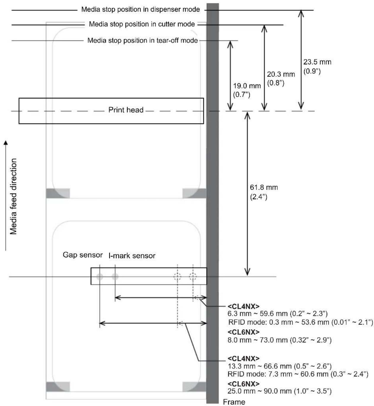

CAUTION
For the CL4NX RFID model, the position of the I-mark sensor becomes 0.3 mm at minimum when the position of the gap sensor is adjusted to around 7.3 mm. Because of this, the paper end may be frequently detected when Paper End in the Printing > Advanced menu is set to Using I-mark (the default), affected by meandering of the media or other causes. When you have adjusted the position of the Gap sensor to around 7.3 mm, change Paper End to Using Gap.
7.3 Replacing the Print Head
You can easily remove and replace a damaged or worn print head.

WARNING
- Do not touch the power button, connect or disconnect the power cord while your hands are wet. Doing so could cause an electric shock.
- Disconnect the power cord from the AC outlet before you replace the print head.
- Wear gloves before replacing the print head, to prevent damage to the print head.
1
Make sure that the printer is in power off mode, then disconnect the power cord from the AC outlet.
2
Open the top cover.

CAUTION
Open the top cover fully to prevent accidental drop of the cover.
3
Push the head lock lever ① towards the rear to unlock the print head.

CAUTION
- The print head and its surroundings are hot after printing. Be careful not to touch it, to avoid being burned.
- Touching the edge of the print head with your bare hand could cause injury.
4
Remove the media and ribbon if they are already loaded.
Refer to Section 3.3 Removing the Ribbon and the reverse procedure in Section 3.5 Loading Media.

natural_image
Technical line drawing of a mechanical device with internal components and mounting bracket (no text or symbols)5 Press the lever ② to remove the print head ③.
CAUTION (for CL4NX only)
For UHF RFID models, the UHF RFID antenna is installed on the print head. Be careful not to overly pull the antenna cable when replacing the print head. Contact your SATO reseller or technical support center for more information.
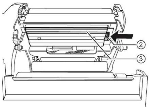
6 Disconnect all the connectors ④ from the defective print head ③.
In total, there are two connectors for CL4NX and three connectors for CL6NX.
7 Connect all the connectors ④ to the new print head.
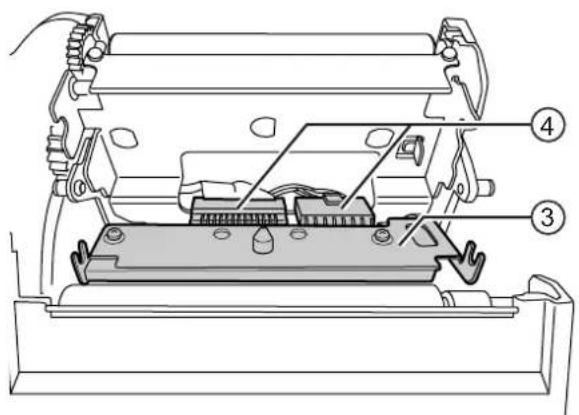
CAUTION
Handle the print head with care. Do not contaminate or scratch the sensitive print head surface.
8 Install the new print head.
Install the print head so that it is locked with a click sound.
9 Load the media and ribbon back if you remove them in step 4.
Refer to Section 3.5 Loading Media and Section 3.2 Loading the Ribbon.
7.4 Replacing the Platen Roller
You can easily remove and replace a damaged or worn platen roller.

WARNING
- Do not touch the power button, connect or disconnect the power cord while your hands are wet. Doing so could cause an electric shock.
- Disconnect the power cord from the AC outlet before you replace the platen roller.
1
Make sure that the printer is in power off mode, then disconnect the power cord from the AC outlet.
2
Open the top cover.

CAUTION
Open the top cover fully to prevent accidental drop of the cover.
3
Push the head lock lever ① towards the rear to unlock the print head.

CAUTION
- The print head and its surroundings are hot after printing. Be careful not to touch it, to avoid being burned.
- Touching the edge of the print head with your bare hand could cause injury.
4
Lift the lever ② in the direction ① to unlock the platen roller ③, then pull out the platen roller ③ in the direction ②.
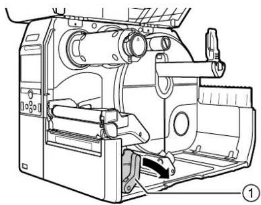
natural_image
Technical line drawing of a mechanical device with internal components and no visible text or symbols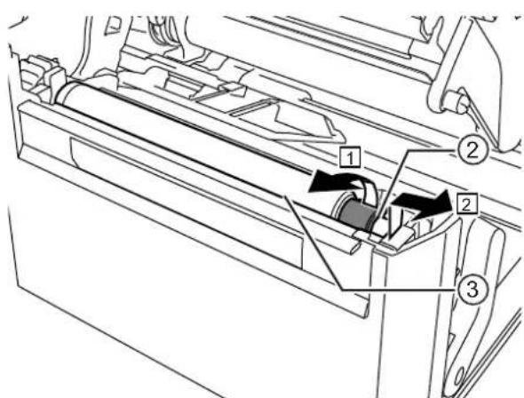
5 Install the new platen roller. Make sure that the first tab ④ on the driving end of the platen roller is pointing upward. Then push the platen roller in the direction ③ so that the first tab ④ is fixed in the groove ⑤ at the driving side.
6 Next, make sure that the second tab ⑥ on the driven end of the platen roller is pointing upward. And then push the platen roller again in the direction ③so that the second tab ⑥ is fixed in the groove ⑦ at the driven side.
7 Turn the lever ② back to lock the platen roller.
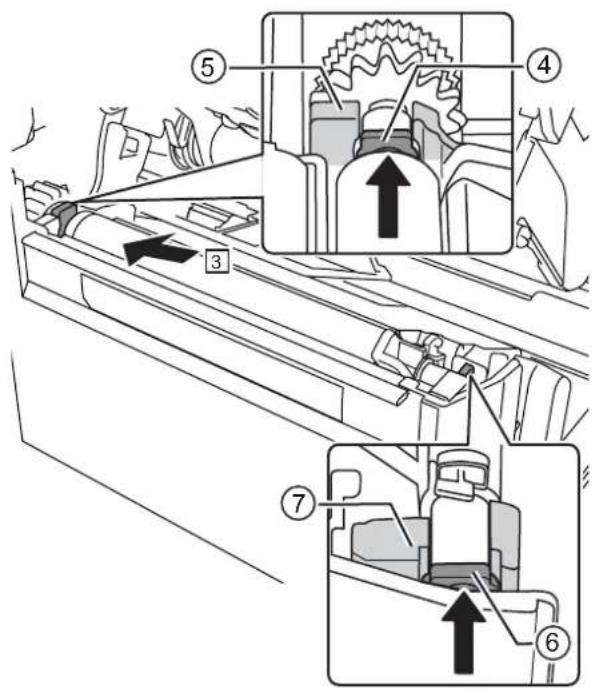
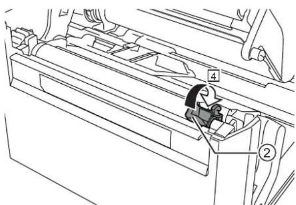
7.4.1 Guideline to Replace the Linerless Platen Roller (CL4NX only)
The linerless platen roller has a blue striped marking on the left side. When the blue striped marking started to fade off, it indicates that you should replace the linerless platen roller.
This is only a general guideline, the condition of the platen roller wears out varies depending on the used media. In any cases, replace the worn platen roller when it affected the printing quality of the printer.
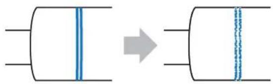
natural_image
Diagram showing a cylindrical object with blue vertical lines and an arrow indicating transformation (no text or symbols)7.5 Optional RFID Configuration (CL4NX only)
This chapter explains the procedures on how to configure the printer to encode your inlays.
1 Examine the media to determine the printer settings.
Refer to the CL4NX Inlay Configuration Guide* for the measurements you should take and what they mean, as well as a list of inlays and their required configurations.
* To see the CL4NX Inlay Configuration Guide, access the following URL: http://www.satoworldwide.com/rfid/
2 Press the ⏻ power button on the operator panel for more than one second to power on the printer.
3 When the printer is in online mode, press the ▶button on the operator panel to change to offline mode.
4 Press the ← button to show the Settings menu.
5 Press the ◀buttons to select Interface and then press the ◀button.
6 Press the ▲/▼ buttons to select RFID and then press the ◀button.
The RFID screen shows.
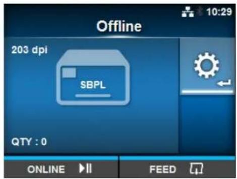
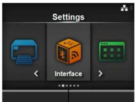
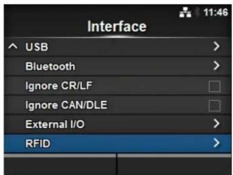
7 Press the ▲buttons to select the item you want to set. Then press the ◀button to go to the adjustment screen.
Refer to Interface > RFID (CL4NX only) menu of Section 4.3 Settings Menu Tree Structure for details on the configuration items.
8 Open the top cover ①.
CAUTION
Open the top cover fully to prevent accidental drop of the cover.
9 Push the head lock lever ② towards the rear to unlock the print head.
CAUTION
• The print head and its surroundings are hot after printing. Be careful not to touch it, to avoid being burned.
- Touching the edge of the print head with your bare hand could cause injury.
| RFID | |
| Antenna Pitch | Standard |
| Write Power | 10 dBm |
| Read Power | 10 dBm |
| Tag Offset | 0 mm |
| Reader Model | M6e Micro |
| Reader Version | 01.01.00.EA |


natural_image
Technical line drawing of a mechanical device with internal components and no visible text or symbols10 Adjust the position of the RFID antenna. Rotate the dial ③ to align the pointer ④ with the media being used.
When the Antenna Pitch is set to Standard in the Interface > RFID menu, adjust the physical position of the antenna according to the settings required for the specific media and inlay used. Refer to the "Antenna Position" of the Inlay Placement & Configuration Table in the CL4NX Inlay Configuration Guide*.
* To see the CL4NX Inlay Configuration Guide, access the following URL: http://www.satoworldwide.com/rfid/
11 Load the media and ribbon.
Refer to Section 3.2 Loading the Ribbon and Section 3.5 Loading Media for details.
12 Confirm the operation by printing/encoding a media.
Make sure that you read the data and check that it is correctly encoded.
7.5.1 Printing RFID Tag Errors
If the recorded data on a tag is incomplete due to writing on a defective tag, the printer will print an RFID tag error to the defective media. This function is to prevent the distribution of defective media with a tag error.
When an RFID tag error occurs, the printer prints a slash and the error message, such as "WRITE TAG ERROR" or "TAG NOT FOUND". The position to print the message and slash is set using the specified media size command
For a write error such as "WRITE TAG ERROR", the printer continues to print the first sixteen or thirty-two bytes of the write data.
The diagram below shows the message and slash printed on the position based on the media size specified by the normal print.
For other errors, the printer prints the error message accordingly.
The dump is printed for the first sixteen or thirty-two bytes of data.
Dotted line shows the range specified with media size command
The dump is printed for the first sixteen or thirty-two bytes of data.
When a character overlaps with the slash, the character will inverse from black to white.
Dotted line shows the range specified with media size command
*(0,0): The origin of the range specified by the media size command
When using a small-size label (about the size of P30 X W40 mm, for example) or not enough for setting margin, the slash and error message are printed overlap on each other. The overlapped area are inverse from black to white. There is no dump printing.
If not specified by the media size command
For other errors, the printer prints the error message accordingly.
The types of errors to print are as follows:
| Message Cause and Countermeasure | ||
| TAG NOT FOUND Cause | : Did not find the tag to print, or failed to read the tag. | |
| Countermeasure: Confirm the inlay operation and check the printer/antenna configuration. | ||
| WRITE TAG ERROR Cause | : Failed to write the tag. | |
| Countermeasure: Confirm the inlay operation and check the printer/antenna configuration. | ||
| PROTECT (TAG)ERROR | Cause: 1. Tried to write to a locked tag.2. Tried to write to an address that is not permitted. | |
| Countermeasure: Use media that is not locked. | ||
| VERIFY TAGERR(OR) | • Only for ISO/IEC 15693, ISO/IEC 14443 Type A | |
| Cause: The written data and read data do not match. | ||
| Countermeasure: Confirm the inlay operation and check the printer/antenna configuration. | ||
| • Only for FeliCa | ||
| Cause: The written data and read data do not match. A value greater than original data was written to subtraction register. | ||
| Countermeasure: Write an appropriate value to subtraction register. | ||
| LOCKING ERROR Cause | : Failed to lock the tag. | |
| Countermeasure: Check the media. | ||
| WRONG TID ERROR • Only for ISO/IEC 15693 | ||
| Cause: Read the UID of the tag other than the specified tag. | ||
| Countermeasure: Check the tag type setting and the label. | ||
| MULTI TAGS ERROR • Only for ISO/IEC 15693, ISO/IEC 14443 Type A | ||
| Cause: Multiple tags detected at a time. | ||
| Countermeasure: Confirm the inlay operation and check the printer/antenna configuration. | ||
| • Only for FeliCa | ||
| Cause: The captured IDm of the card is inconsistent between processes. (Tried to write to a wrong card.) | ||
| Countermeasure: Confirm the inlay operation and check the printer/antenna configuration. | ||
| DIFFER EPC ERROR • Only for UHF | ||
| Cause: Detected inconsistent EPC during a series of processes. | ||
| Countermeasure: Check the media. | ||
| CHIP MAKER ERR. • Only for UHF | ||
| Cause: Incorrect tag chip maker is specified when specifying the MCS setting and encoding the SGTIN96. | ||
| Countermeasure: Check the media, and correct the tag chip maker. | ||
| MCS NOT SUPPORT • Only for UHF | ||
| Cause: Unsupported inlay (IC chip) is used when specifying the MCS setting and encoding the SGTIN96. | ||
| Countermeasure: Check the media, and change it to supported inlay. | ||
7.5.2 RFID Error and Reset Timing
Error signal output with one-shot pulse
Error signal output with long pulse
When the reprint count reaches the specified number, the RFID tag error and Machine error are outputted at a time. The machine error output is always a long pulse.
Timing chart of error signal output with one-shot pulse
| Item | RFID reprint twice - One-shot Pulse Output Waveform |
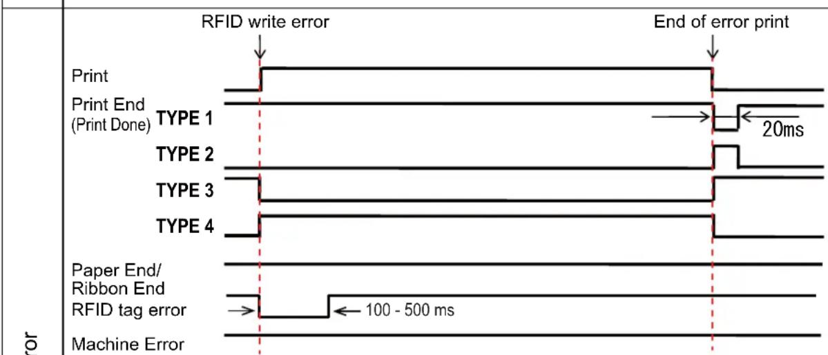 | |
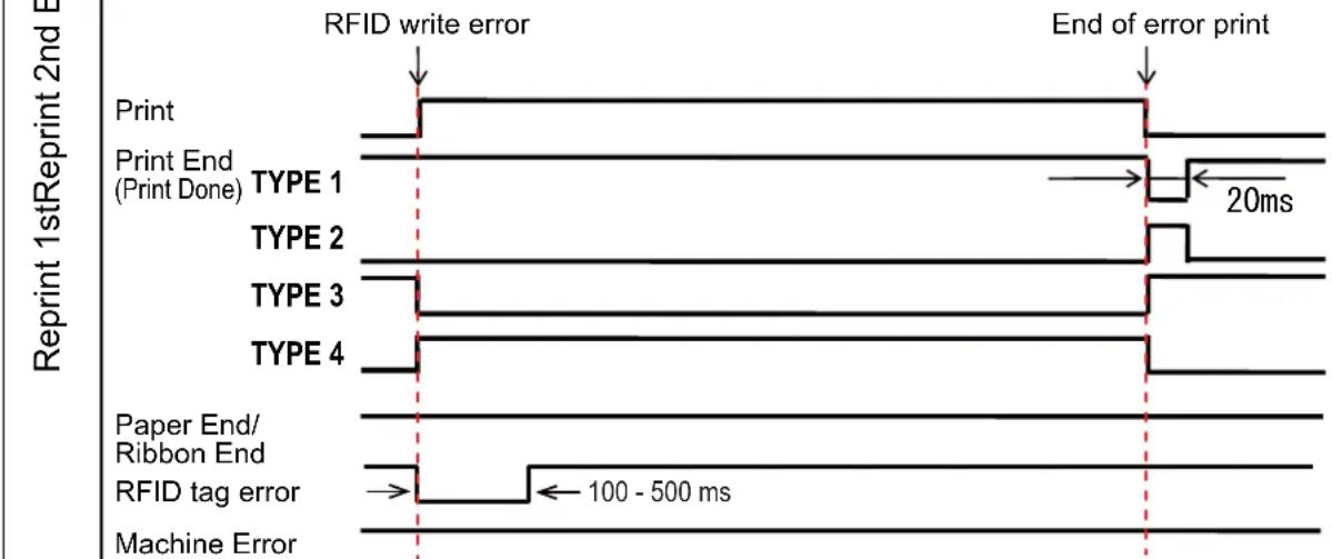 | |
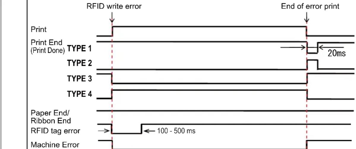 |
Timing chart of error signal output with long pulse
| Item | RFID reprint twice - Level Output Waveform | |
| RFID write error | End of error print | |
| Reprint 1stReprint 2nd Error | Print Print End (Print Done) TYPE 1 | 20ms |
| TYPE 2 | ||
| TYPE 3 | ||
| TYPE 4 | ||
| Paper End/ Ribbon End | ||
| RFID tag error | ||
| Machine Error | ||
| RFID write error | End of error print | |
| Print Print End (Print Done) TYPE 1 | 20ms | |
| TYPE 2 | ||
| TYPE 3 | ||
| TYPE 4 | ||
| Paper End/ Ribbon End | ||
| RFID tag error | ||
| Machine Error | ||
| RFID write error | End of error print | |
| Print Print End (Print Done) TYPE 1 | 20ms | |
7.5.3 External (EXT) Signal Interfaces when RFID Mode is Enabled
Comparison of EXT signal between RFID Mode is disabled or enabled.
RFID Mode disabled. RFID Mode enabled.
| Pin No. | Signal I/O Pin No. Signal I/O | |
| 1 Paper End Output | ||
| 2 | G r o u | n d |
| 3 Ribbon End Output | ||
| 4 Machine Error Output | ||
| 5 | Print Start (PRIN) | Input |
| 6 | Print Done/End (PREND) | Output |
| 7 | Reprint (PRIN2) | Input |
| 8 | External Power Supply | Input |
| 9 Online Output | ||
| 10 | Ribbon Near End | Output |
| 11 | N/A | - |
| 12 | +24V | Output |
| 13 | +5V | Output |
| 14 | Frame Ground | - |
| 1 Paper End + Ribbon End Output | ||
| - | 2 G r | o u |
| 3 RFID Tag Error Output | ||
| 4 Machine Error/RFID Error Output | ||
| 5 | Print Start (PRIN) | Input |
| 6 | Print Done/End (PREND) | Output |
| 7 | Reprint (PRIN2) | Input |
| 8 | External Power Supply | Input |
| 9 Online | Output | |
| 10 | Ribbon Near End | Output |
| 11 | N/A | - |
| 12 | +24V | Output |
| 13 | +5V | Output |
| 14 | Frame Ground | - |
Standard specification is applied when the RFID Mode is set to Disabled. Functions shown by shading are applied when the RFID Mode is set to Enabled.
7.5.4 RFID Printing Tips
Recommended non-printable zone
Avoid printing barcodes or characters directly on top of an RFID chip. The uneven surface will negatively affect the print quality.

Feed direction
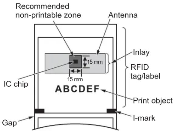
7.6 Printer Specifications
Specifications are subject to change without notice.
7.6.1 Hardware
| Model CL4NX CL6NX | ||
| Dimensions and Weight | ||
| Width 271 mm (10.67") | 338 mm (13.31") | |
| Height 321 mm (12.64") | 321 mm (12.64") | |
| Depth 457 mm (18.00") | 457 mm (18.00") | |
| Weight Approximately | 15.1 kg (33.28 lbs.) Approximately 20.3 kg (44.75 lbs.) | |
| Power Supply | ||
| Input Voltage AC 100 V | -240 V ±10% | |
| Frequency 50 - 60 Hz | ||
| Power Consumption At | peak: 180 W / 190 VA(Print ratio 30%)Standby: 20 W / 40 VA | At peak: 240 W / 308 VA(Print ratio 30%)Standby: 23 W / 63 VA |
| Processing | ||
| Flash ROM CPU1: 2 GB, CPU2: 4 MB | ||
| SDRAM | CPU1: 256 MB, CPU2: 64 MB | |
| User Registration Area | Maximum 679 MB | |
| Receive Buffer | Maximum: 2.95 MBNear full: 2 MB | |
| Operation | ||
| LCD | TFT color 3.5 inch (88.9 mm) | |
| LED | STATUS: Blue/Red | |
| Display Language | English / German / French / Spanish / Italian / Portuguese / Czech / Danish / Dutch / Finnish / Greek / Hungarian / Norwegian / Polish / Romanian / Russian / Slovak / Swedish / Turkish / Chinese (Simplified) / Chinese (Traditional) / Korean / Japanese / Arabic / Thai / Vietnamese / Persian / Indonesian / Hindi / Bulgarian | |
| Environmental Conditions (Without Media and Ribbon) | ||
| Operating Temperature | Continuous/Cutter/Tear-off mode:0 to 40 °C (32 to 104 °F)Dispenser/Linerless mode:5 to 35 °C (41 to 95 °F) | Continuous/Cutter/Tear-off mode:0 to 40 °C (32 to 104 °F)Dispenser mode:5 to 35 °C (41 to 95 °F) |
| Storage Temperature | -20 to 60 °C (-4 to 140 °F) | |
| Operating Humidity Continuous/Dispenser/Cutter/Tear-off mode:30 to 80% RH (Non-condensing)Linerless mode: 30 to 75% RH(Non-condensing) | 30 to 80% RH (Non-condensing) | |
| Storage Humidity 30 to 90% RH (Non-condensing) | ||
| Print Method Direct thermal and thermal transfer | ||
| Print Speed 203 dpi: 2 to 10 inch/sec(50.8 to 254 mm/sec)305 dpi: 2 to 8 inch/sec(50.8 to 203.2 mm/sec)609 dpi: 2 to 6 inch/sec(50.8 to 152 mm/sec)Linerless mode: 2 to 6 inch/sec(50.8 to 152 mm/sec) | 203 dpi: 2 to 10 inches/sec(50.8 to 254 mm/sec)305 dpi: 2 to 8 inches/sec(50.8 to 203.2 mm/sec) | |
| Resolution 203 dpi (8 dots/mm)305 dpi (12 dots/mm)609 dpi (24 dots/mm) | 203 dpi (8 dots/mm)305 dpi (12 dots/mm) | |
| Non-printable Area Pitch direction (Excludes liner)Top: 1.5 mm (0.06"), Bottom: 1.5 mm (0.06")Width direction (Excludes liner)Left: 1.5 mm (0.06"), Right: 1.5 mm (0.06") | ||
| Printable Area 203 dpi: Length 2500 mm (98.42") xWidth 104 mm (4.09")305 dpi: Length 1500 mm (59.05") xWidth 104 mm (4.09")609 dpi: Length 400 mm (15.75") xWidth 104 mm (4.09") | 203 dpi: Length 2500 mm (98.42") xWidth 152 mm (5.98")305 dpi: Length 1500 mm (59.05") xWidth 165.3 mm (6.50")* When Head Base Position is set to Left-justify: maximum print width 167.5 mm (6.59"). | |
| Print End Position 203 dpi: 1 to 20000 dots305 dpi: 1 to 18000 dots609 dpi: 1 to 9600 dots | 203 dpi: 1 to 20000 dots305 dpi: 1 to 18000 dots | |
| Print Darkness Darkness level: 1 to 10Darkness range: ASensors | ||
| I-mark(Reflective Type) | Position and sensitivity: Adjustable | |
| Gap(Transmissive Type) | Position and sensitivity: Adjustable | |
| Head Open Fixed | ||
| Paper End Sensor Detect with I-mark sensor or Gap sensor | ||
| Ribbon End/Ribbon Near End | Fixed | |
| Dispenser Fixed | * If linerless kit or dispenser unit is installed. | Fixed* If the dispenser unit is installed. |
| Cutter Fixed | * If cutter unit or linerless kit is installed. | Fixed* If the cutter unit is installed. |
7.6.2 Ribbon and Media
| Model CL4NX | CL6NX | |
| Ribbon (Use genuine ribbon made by SATO.) | ||
| Size Length: maximum 600 m (1968.5 ft.)Width: 39.5 mm to 128 mm(1.55" to 5.04")*When the width is 39.5 mm (1.55"), the maximum length is 450 m (1476.4 ft.).* The maximum length varies depending on the ribbon type.* Use the ribbon that is wider than the media. | Length: maximum 600 m (1968.5 ft.)Width: 59 mm to 177 mm(2.32" to 6.98")* The maximum length varies depending on the ribbon type.* Use the ribbon that is wider than the media. | |
| Wind Direction Face-out/Face-in | ||
| Winding Method Coreless | ||
| Media (Use genuine media made by SATO.) | ||
| Type Media roll (Face-in wound/face-out wound), Fan-fold media | ||
| Size | ||
| Continuous | ||
| Pitch 203 dpi: 6 | to 2497 mm (0.24" to 98.30")305 dpi: 6 to 1497 mm (0.24" to 58.94")609 dpi: 6 to 397 mm (0.24" to 15.63")RFID mode: 13 to 240 mm(0.51" to 9.45") | 203 dpi: 16 to 2497 mm (0.63" to 98.30")305 dpi: 16 to 1497 mm (0.63" to 58.94") |
| (With Liner) 203 | dpi: 9 to 2500 mm (0.35" to 98.42")305 dpi: 9 to 1500 mm (0.35" to 59.05")609 dpi: 9 to 400 mm (0.35" to 15.75")RFID mode: 16 to 243 mm(0.63" to 9.57") | 203 dpi: 19 to 2500 mm (0.75" to 98.42")305 dpi: 19 to 1500 mm (0.75" to 59.05") |
| Width(With Liner) | 22 to 128 mm (0.87" to 5.04")25 to 131 mm (0.98" to 5.16") | 47 to 177 mm (1.85" to 6.96")50 to 180 mm (1.97" to 7.01") |
| Model CL4NX | CL6NX | ||
| Media (Use genuine media made by SATO.) | |||
| Size | |||
| Tear-off/Cutter | |||
| Pitch(With Liner) | 203 dpi: 17 to 2497 mm (0.67" to 98.30")305 dpi: 17 to 1497 mm (0.67" to 58.94")609 dpi: 17 to 397 mm (0.67" to 15.63")RFID mode: 17 to 240 mm(0.67" to 9.45") | 203 dpi: 17 to 2497 mm (0.67" to 98.30")305 dpi: 17 to 1497 mm (0.67" to 58.94") | |
| 203 dpi: 20 to 2500 mm (0.79" to 98.42")305 dpi: 20 to 1500 mm (0.79" to 59.05")609 dpi: 20 to 400 mm (0.79" to 15.75")RFID mode: 20 to 243 mm(0.79" to 9.57")* When Print Mode is set to Cut & Print,the minimum pitch for each print speedis the following value:2 ips: 40 mm (1.57"), 3 ips: 58 mm (2.28"),4 ips: 75 mm (2.95"), 5 ips: 93 mm (3.66"),6 ips: 110 mm (4.33"), 7 ips: 125 mm (4.92"),8 ips: 140 mm (5.51"), 9 ips: 156 mm (6.14"),10 ips: 171 mm (6.73") | 203 dpi: 20 to 2500 mm (0.79" to 98.42")305 dpi: 20 to 1500 mm (0.79" to 59.05")* When Print Mode is set to Cut & Print,the minimum pitch for each print speedis the following value:2 ips: 40 mm (1.57"), 3 ips: 58 mm (2.28"),4 ips: 75 mm (2.95"), 5 ips: 93 mm (3.66"),6 ips: 110 mm (4.33"), 7 ips: 125mm (4.92"),8 ips: 140 mm (5.51"), 9 ips: 156 mm (6.14"),10 ips: 171 mm (6.73") | ||
| Width(With Liner) | 22 to 128 mm (0.87" to 5.04")25 to 131 mm (0.98" to 5.16") | 47 to 177 mm (1.85" to 6.96")50 to 180 mm (1.97" to 7.01") | |
| Dispenser | |||
| Pitch 203/305/60(With Liner) | 09 dpi: 27 to 397 mm(1.06" to 15.63")RFID mode: 27 to 240 mm(1.06" to 9.45") | 203/305 dpi: 27 to 397 mm(1.06" to 15.63") | |
| 305/609 dpi: 30 to 400 mm(1.18" to 15.75")RFID mode: 30 to 243 mm(1.18" to 9.57") | 203/305 dpi: 30 to 400 mm(1.18" to 15.75") | ||
| Width(With Liner) | 22 to 128 mm (0.87" to 5.04")25 to 131 mm (0.98" to 5.16") | 47 to 177 mm (1.85" to 6.97")50 to 180 mm (1.97" to 7.01") | |
| Diameter of Liner Winding | Maximum 120 mm (4.72") | ||
| Linerless | |||
| Pitch 30 to 120 | mm (1.18" to 4.72") — | ||
| Width 60 to 118 | mm (2.36" to 4.65") — | ||
| Roll Diameter(Media Roll) | Maximum 220 mm (8.66")When using a dispenser with liner rewinder: maximum 220 mm (8.66") | ||
| Core Diameter (Media Roll) | 76 mm, 101 mm (3", 4")When using a dispenser with liner rewinder: 76 mm (3")* Recommend to use 4" core for thick paper (more than 150 μm), non-adhesive media and RFID tags (CL4NX only)/labels. | ||
| Height (Fan-fold Media) | Maximum 200 mm (7.87")* When the printer and media are configured to the same height. | ||
| Thickness 0.08 to 0.268 mm (0.0031" to 0.011") 0.06 to 0.268 mm (0.0024" to 0.011") | |||
Note
The usable media sizes, the print speed and print quality vary depending on the media specification, media and ribbon combination, printer settings and printing environment. It is recommended to perform a test print with the media and ribbon to be used in advance.
7.6.3 Interface
| Model CL4NX CL6NX | |||
| Interface | |||
| Standard | Built-in USB Interface (Type B)LAN InterfaceBluetooth InterfaceUSB Interface (Type A) x 2 | ||
| Extension Board | RS-232C InterfaceIEEE1284 InterfaceExternal Signal Interface (EXT) | ||
| Option Board Wireless LAN Interface | |||
| RFID | UHF(920 MHz) | ISO/IEC 18000-6 Type C Gen2 — | |
| HF(13.56 MHz) | ISO/IEC 15693 (ICODE SLI/SLIX/SLIX-S, Tag-it HF-I, my-d)ISO/IEC 14443 Type A (NTAG203, NTAG210, NTAG213/215/216, MIFARE UltraLight, MIFARE UltraLight C, my-d move NFC)ISO/IEC 18092 (FeliCa Lite-S) | — | |
7.6.4 Built-in Functions
| Model CL4NX CL6NX | ||
| Functions | ||
| Built-in Functions Status return | GraphicSequential numberForm overlayCharacter modificationBlack/white inversionRuled lineDump listFormat registrationOutline fontOutline modificationZero slash switchingGuidance Video | |
| Self-diagnosis Functions Broken head element check | Head open detectionPaper end detectionRibbon near-end detectionTest printCutter open check (If cutter unit is installed)Label detection at dispensing (If dispenser unit is installed) | |
| Adjustment Functions Print | DarknessPrint PositionMedia Stop PositionBuzzerLCD Brightness | |
7.6.5 Printer Languages
| Model CL4NX CL6NX | ||
| Printer Languages | ||
| SBPL (Includes XML support)SZPLSDPLSIPLSTCLAEP | ||
7.6.6 Fonts/Symbols/Barcodes
| Model CL4NX CL6NX | ||
| Fonts | ||
| Bitmap Fonts | ||
| U 9 dots H x 5 dots W | ||
| S 15 dots H x 8 dots W | ||
| M 20 dots H x 13 dots W | ||
| WB 30 dots H x 18 dots W | ||
| WL 52 dots H x 28 dots W | ||
| XU 9 dots H x 5 dots W | ||
| XS 17 dots H x 17 dots W | ||
| XM 24 dots H x 24 dots W | ||
| XB 48 dots H x 48 dots W | ||
| XL 48 dots H x 48 dots W | ||
| X20 9 dots H x 5 dots W | ||
| X21 17 dots H x 17 dots W | ||
| X22 24 dots H x 24 dots W | ||
| X23 48 dots H x 48 dots W | ||
| X24 48 dots H x 48 dots W | ||
| OCR-A 203 dpi: 22 dots H x | 15 dots W305 dpi: 33 dots H x 22 dots W609 dpi: 66 dots H x 44 dots W | 203 dpi: 22 dots H x 15 dots W305 dpi: 33 dots H x 22 dots W |
| OCR-B 203 dpi: 24 dots H x | 20 dots W305 dpi: 36 dots H x 30 dots W609 dpi: 72 dots H x 60 dots W | 203 dpi: 24 dots H x 20 dots W305 dpi: 36 dots H x 30 dots W |
| JIS208 Kanji Fonts(Mincho/Gothic) | 16 dots H x 16 dots W24 dots H x 24 dots W22 dots H x 22 dots W32 dots H x 32 dots W40 dots H x 40 dots W | |
| JIS0213 Kanji Fonts(Gothic) | 16 dots H x 16 dots W24 dots H x 24 dots W22 dots H x 22 dots W32 dots H x 32 dots W40 dots H x 40 dots W | |
| Compatible Kanji Fonts(Mincho) | 16 dots H x 16 dots W24 dots H x 24 dots W | |
| Simplified ChineseCharacters | 16 dots H x 16 dots W24 dots H x 24 dots W | |
| Traditional Chinese Characters | 24 dots H x 24 dots W | |
| Korean Fonts 16 dots H x 16 | 6 dots W24 dots H x 24 dots W | |
| Scalable Fonts | ||
| Rasterized Font SATO CG | SleekSATO CG StreamSATO 0SATO Alpha Bold CondensedSATO Beta Bold ItalicSATO Folio BoldSATO Futura Medium CondensedSATO GammaSATO OCR-ASATO OCR-BSATO SansSATO SerifSATO VicaSATO Hebe SansSATO Hebe Sans ArabicSATO Hebe Sans ThaiSATO Hebe Sans HebrewSATO Hebe Sans HindiSATO Gothic Traditional ChineseSATO Gothic JapaneseSATO Gothic Simplified ChineseSATO Gothic KoreanSATO Silver SerifSATO Mincho Traditional ChineseSATO Mincho JapaneseSATO Mincho Simplified ChineseSATO Mincho KoreanSATO Roman ArabicSATO Symbol SetSATO WingBats | |
| Outline Fonts Helvetica Outline Font | ||
| JIS208 Kanji Outline Fonts | ||
| Model CL4NX CL6NX | |
| Barcodes | |
| 1D Barcodes UPC-A/UPC-E | JAN/EAN-13/8CODE39, CODE93, CODE128GS1-128(UCC/EAN128)CODABAR(NW-7)ITFIndustrial 2 of 5Matrix 2 of 5MSICustomer BarcodePOSTNETUPC add-on codeUSPSBOOKLANDGS1 DataBar OmnidirectionalGS1 DataBar TruncatedGS1 DataBar StackedGS1 DataBar Stacked OmnidirectionalGS1 DataBar LimitedGS1 DataBar ExpandedGS1 DataBar Expanded Stacked |
| 2D Codes QR Code | Micro QR CodePDF417Micro PDFMaxi CodeGS1 Data MatrixData Matrix (ECC200)Aztec Code |
| Composite Symbols EAN-13 | Composite (CC-A/CC-B)EAN-8 Composite (CC-A/CC-B)UPC-A Composite (CC-A/CC-B)UPC-E Composite (CC-A/CC-B)GS1 DataBar Composite (CC-A/CC-B)GS1 DataBar Truncated Composite (CC-A/CC-B)GS1 DataBar Stacked Composite (CC-A/CC-B)GS1 DataBar Expanded Stacked Composite (CC-A/CC-B)GS1 DataBar Expanded Composite (CC-A/CC-B)GS1 DataBar Stacked Omnidirectional Composite (CC-A/CC-B)GS1 DataBar Limited Composite (CC-A/CC-B)GS1-128 Composite (CC-A/CC-B/CC-C) |
7.6.7 Options
| Model CL4NX CL6NX | ||
| Options | ||
| 1) Cutter unit2) Linerless cutter kit3) Dispenser unit (with internal liner rewinder)4) Simple dispenser kit5) Internal liner rewinder kit6) RTC (Calendar) kit7) UHF RFID kit8) HF RFID kit9) Wireless LAN interface kit10)Combo interface board (RS-232C, IEEE1284, and EXT)11)External rewinder (RWG-500) | 1) Cutter unit2) Dispenser unit (with internal liner rewinder)3) Simple dispenser kit4) Internal liner rewinder kit5) RTC (Calendar) kit6) Wireless LAN interface kit7) Combo interface board (RS-232C, IEEE1284, and EXT)8) External rewinder (RWG-500) | |
7.6.8 Accessories
| Model CL4NX CL6NX | ||
| Accessories | ||
| 1) Power cord2) Documentations (Quick Guide, Global Warranty Program leaflet, etc.) | ||
7.6.9 Standards
| Model CL4NX CL6NX | |||
| Standards | |||
| Safety Standards | UL 60950-1CSA C22.2 No.60950-1EN60950-1CCCKCRCMIRAMBISEAC | ||
| EMC Standards FCC-B, FCC-CICES-003, ICEN55022 Class A, EN55024, R&TTECCC, SRRCKCIDASIRIMPTQCNTCDGPTRCMIRAM, CNCANATELWPC | |||
| Environmental Standard RoHS | RoHS directive (six hazardous) restricts the use of six hazardous materials listed below.Hexavalent chromium . . . . . . . . . . . . . . . . . . . . . . . . . . . . . . . . . . . . . . . . . . . . . . . . . . . . . . . . . . . . . . . . . . . . . . . . . . . . . . . . . . . . . . . . . . . . . . . . . . . . Lead and lead compounds . . . . . . . . . . . . . . . . . . . . . . . . . . . . . . . . . . . . . . . . . . . . . . . . . . . . . . . . . . . . . . . . . . . . . . . . . . . . . . . . . . . . . . . . . . . . . . . . . . . Mercury and mercury compounds . . . . . . . . . . . . . . . . . . . . . . . . . . . . . . . . . . . . . . . . . . . . . . . . . . . . . . . . . . . . . . . . . . . . . . . . . . . . . . . . . . . . . . . . . . . . . . . . . . Polybrominated biphenyls (PBB) . . . . . . . . . . . . . . . . . . . . . . . . . . . . . . . . . . . . . . . . . . . . . . . . . . . . . . . . . . . . . . . . . . . . . . . . . . . . . . . . . . . . . . . . . . . . . . . . . . . Polybredinated diphenyl ethers (PBDE) . . . . . . . . . . . . . . . . . . . . . . . . . . . . . . . . . . . . . . . . . . . . . . . . . . . . . . . . . . . . . . . . . . . . . . . . . . . . . . . . . . . . . . . . . . . . . . . . . . Energy Saving International | ENERGY STAR program | |
7.7 Interface Specifications
For data communication with the host, this printer supports the following interfaces: You can set the various interface settings of the printer through Interface in the Settings menu.
- USB (USB type B)
• LAN Ethernet - Bluetooth
• RS-232C (DB 9 pins, female)
• IEEE1284 (Amphenol 36 pins) - External signal (EXT) (Amphenol 14 pins)
- Wireless LAN

CAUTION
Do not connect or disconnect the interface cables (or use a switch box) with power supplied to either the printer or host. This may cause damage to the interface circuitry in the printer or host and is not covered by warranty.
Note
- Wireless LAN is an optional interface.
- You cannot use the wireless LAN interface and LAN interface at a time.
7.7.1 USB Interface
This interface complies with the USB2.0 standard. Install the USB driver to the computer before use.
| Basic Specifications | |
| Connector USB Type B connector | |
| Protocol Status4, Status5 | |
| Power Supply BUS Power through cable | |
| Pin Assignments | |
| Pin No. Description | |
| 1 VBus | |
| 2 | - |
| 3 | + |
| 4 | GND |
D
D
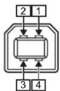
a
a
| Cable Specifications | |
| Cable Connector USB Type B | connector |
| Cable Length 5 m (16.4 feet) or less | |
7.7.2 LAN Ethernet Interface
| Basic Specifications | |
| Connector RJ-45 Receptacle | |
| Protocol Status3 | Status4Status5 |
| IP Address IPv4 | IPv6 |
| Subnet Mask IPv4 | IPv6 |
| Gateway Address IPv4 | IPv6 |
| Cable Specifications | |
| Cable 10BASE-T/100BASE-TX | Category 5 |
| Cable Length 100 m (328 feet) | or less |
| Software Specifications | |
| Supported Protocol TCP/IP | |
| Network Layer IP, ICMP | |
| Session Layer TCP | |
| Application Layer LPD, FTP, DHCP, HTTPS, SNMP, NTP | |
7.7.3 Bluetooth Interface
This interface complies with the Bluetooth3.0+EDR standard.
| Basic Specifications | |
| Signal Level Class 2 | |
| Communication Distance 10 m | (32.8 feet) |
| Profile Serial Port Profile | |
| Security Level None, level 2, 2-1, 2-2, level 3, level 4 | |
| PIN Code 1 to 16 characters consisting of ASCII code (20H, 21H, 23H to 7EH) | |
| Disconnect Timeout (LMP layer) | 60 seconds |
7.7.4 RS-232C Interface
This interface complies with the RS-232C standard.
| Basic Specifications | |
| Asynchronous ASCII Half-duplex communicationBi-Directional Communication | |
| Data Transmission Rate 2400, | 4800, 9600, 19200, 38400, 57600, 115200 bps |
| Transmission Form Start, b1, b2, b3, b4, b5, b6, b7, b8, Stop“b8” will be omitted if using 7 bit oriented. | |
| Data Length 7 or 8 bit (selected) | |
| Stop Bit 1 or 2 bit (selected) | |
| Parity Bit ODD, EVEN, NONE (selected) | |
| Codes Used ASCII Character Codes: 7 bits, Graphics: 8 bits | |
| Control Codes STX (02H), ETX (03H), ACK (06H), NAK (15H) | |
| Connector DB-9 Female or equivalent | |
| Signal Levels High = +5 to +12 V, Low = -5 to -12 V | |
| Protocol Ready/Busy, XON/XOFF, Status3, Status4, Status5 | |
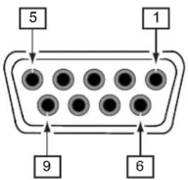
| Connector Pin Specifications | ||
| Pin No. I/O | Description | |
| 1 | - | Data Carrier Detect |
| 2 | Input | Receive Data |
| 3 | Output | Transmit Data |
| 4 | Output | Data Terminal Ready |
| 5 | Reference | Signal Ground |
| 6 | Input | Data Set Ready |
| 7 | Output | Request To Send |
| 8 | Input | Clear To Send |
| 9 | - | Not connected |
| Cable Specifications | |
| Cable Connector DB-9 Male or equivalent | |
| Cable Length 5 m (16.4 feet) or less |
Note
- When using the READY/BUSY control, make sure that the printer is in power on mode before you send the data from the host.
- With communication protocols such as XON/XOFF, STATUS3, STATUS4 or STATUS5, a receive buffer full error will occur when the received data is more than the receive buffer size (2.95 MB). Send data that is less than 2.95 MB while monitoring the status of the printer.
- A parity error will be detected if this error occurs after the reception of ESC+A.
7.7.5 IEEE1284 Interface
This interface complies with the IEEE1284 standard.
| Basic Specifications | |
| Connector Amphenol 36 pins, female | |
| Signal Levels High-level: +2.4 to +5.0 VLow-level: +0.0 to +0.4 V | |
| Receive Mode Single-item buffer, Multi-item buffer |
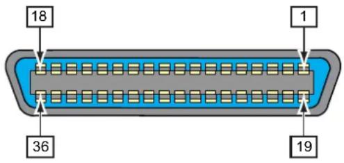
| Connector Pin Specifications | ||
| Pin No. I/O Description | ||
| 1 Input STROBE | ||
| 2-9 Input DATA 1 - DATA 8 | DATA1: LSBDATA8: MSB | |
| 10 Output ACK | ||
| 11 Output BUSY | ||
| 12 Output PAPER EMPTY/PAPER ERROR | ||
| 13 Output SELECT | ||
| 14 | Input AUTO FEED | |
| 15 - | Not in use | |
| 16 - | LOGIC Ground | |
| 17 - | Frame Ground | |
| 18 | +5 V | |
| 19 - | STROBE RETURN | |
| 20-27 | - | DATA 1 - DATA 8 RETURN |
| 28 - | ACK RETURN | |
| 29 - | BUSY RETURN | |
| 30 - | PAPER EMPTY RETURN | |
| 31 | Input INITIALIZE | |
| 32 Output FAULT | ||
| 33-35 - Not in use | ||
| 36 Input SELECT INPUT | ||
| Cable Specifications | |
| Cable Connector Amphenol 36 pins, male | |
| Cable Length 1.5 m (5 feet) or less |
7.7.6 External Signal Interface (EXT)
This interface is designed to connect the printer with other peripherals.
| Basic Specifications | |
| Connector Centronics IDC Type | 14 pins (female) |
| Signal Levels High-level: +4.2 | to +5.0 VLow-level: +0.0 to +0.7 V |
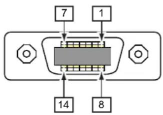
| Connector Pin Specifications | |||
| Pin No. | I/O | Description | Electric Conditions(Voltage, Current (Max)) |
| 1 Output Paper End: | Outputs a low signal when the paper end is detected. | Withstand voltage 50 VSink current 50 mA | |
| 2 - GND: Reference Signal Ground - | |||
| 3 Output Ribbon End: | Outputs a low signal when the ribbon end is detected. | Withstand voltage 50 VSink current 50 mA | |
| 4 Output Machine Error: | Outputs a low signal when an error such as the head open error is detected. | Withstand voltage 50 VSink current 50 mA | |
| 5 Input | Print start signal (PRIN):Prints one media when a low signal is detected. | High: high impedanceLow: more than -15 mA,0 V | |
| 6 Output Print Done/Print end | signal (PREND):Outputs a signal when the media print is completed. | Withstand voltage 50 VSink current 50 mA | |
| 7 Input | Reprint signal (PRIN2):Prints the previously printed content again when a low signal is detected. | High: high impedanceLow: more than -15 mA,0 V | |
| 8 Input | External power supply 5 V | ||
| 9 | Output | • MODE1: The output signal becomes “Active” when there is remaining print data without error in online mode.• MODE2: The output signal becomes “Active” when the printer is Online. | Withstand voltage 50 VSink current 50 mA |
| 10 Output | Ribbon Near End: | Outputs a high signal when the ribbon near end is detected. | Withstand voltage 50 V Sink current 50 mA |
| 11 --- | |||
| 12 - +24 V | ± 10% 2 A | ||
| 13 - Vcc +5 V | 500 mA | ||
| 14 --- | |||
| * Output Dispense completion waiting signal: Outputs a low signal when the dispense is completed.You can set the pin number for output through the Settings > Interface > External I/O > Signals > Outputs menu. | Withstand voltage 50 V Sink current 50 mA | ||
Note
- You can set the external signal (EXT) type (TYPE1 to TYPE4) for Print Done output signal of pin No. 6. Refer to the EXT Mode screen of the Interface > External I/O > Signals menu for details.
- You can set the pin number for input and output through the Settings > Interface > External I/O > Signals > Inputs and Outputs menu.
- The Print Done signal of pin No. 6 is not outputted when 0 is specified in the number of cuts in the command specifying the number of cuts during the cutter operation.
Timing Chart of the EXT Input Signal
| Item | Input Waveform | |
| Print StartReprint (no print | Printed 1 piece | |
| Print Start(PRIN) | ||
| Reprint(PRIN2) | ||
| Print End(Print Done) | TYPE 1 20 ms | |
| TYPE 2 | ||
| TYPE 3 | ||
| TYPE 4 | ||
| Printed 1 piece | ||
| Print Start(PRIN) | ||
| Reprint(PRIN2) | ||
| Print End(Print Done) | TYPE 1 20 ms | |
| TYPE 2 | ||
| TYPE 3 | ||
| TYPE 4 | ||
| Reprint (with print start signal) | Printed 1 piece | |
| Print Start(PRIN) | ||
| Reprint(PRIN2) | More than 10ms | |
| Print End(Print Done) | TYPE 1 20 ms | |
| TYPE 2 | ||
| TYPE 3 | ||
| TYPE 4 | ||
Supplementary explanation
- Keep the print start signal (PRIN) to "Low" until print end signal (Print done) is outputted. Refer to the below Maintaining the Print Start Signal (PRIN) timing chart.
- Keep the output reprint signal (PRIN2) for more than 10 ms. When signal is outputted for shorter than 10 ms, and reprint signal is not acknowledged, the printer does not perform reprinting.
Maintaining the Print Start Signal (PRIN)
| Item | Input Waveform |
 | |
 | |
| Item | Timing Chart |
| Print Done (PREND) Signal | Printed 1 piece |
| Print End (Print Done) TYPE 1 TYPE 2 | |
| TYPE 3 TYPE 4 | |
| T1 < 150 ns T1 T1 |
Rise or fall time (T1) of Print Done signal is less than 150 ns. You have to consider the time when outputting the signal from the connected devices.
- When the print start signal and reprint signal are outputted simultaneously, the print start signal is enabled and the printer does not perform reprinting.
- The reprint signal is valid only from the time of the print operation end (QTY=0) until the next print data reception. Other than that, the printer does not perform reprinting.
Timing Chart of the EXT Output Signal • Standard specification
 |
| Item | Output Waveform |
| Ribbon Near EndOffline Machine Error |  |
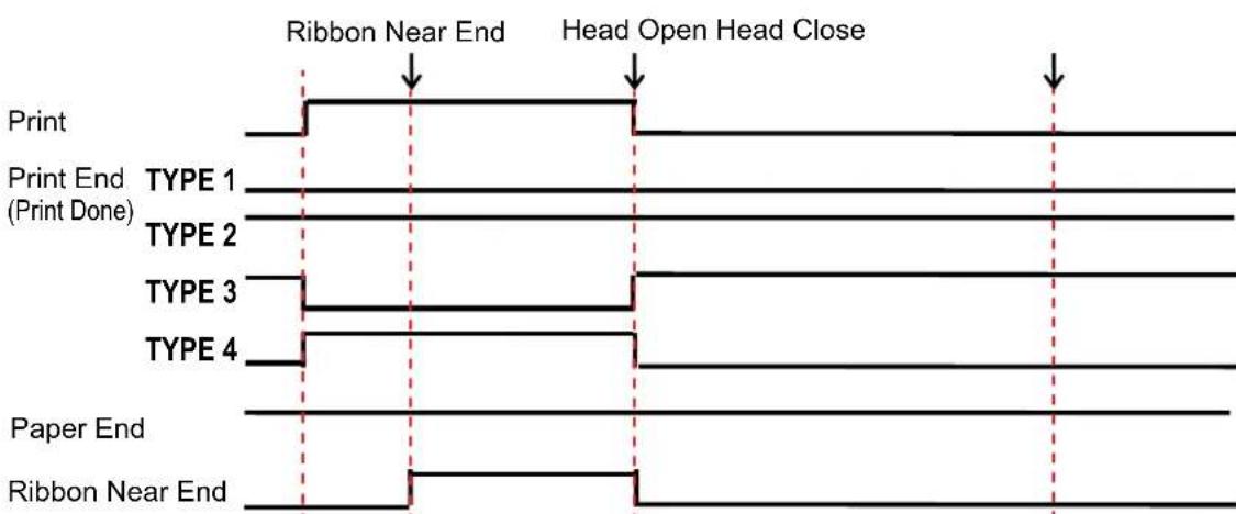 | |
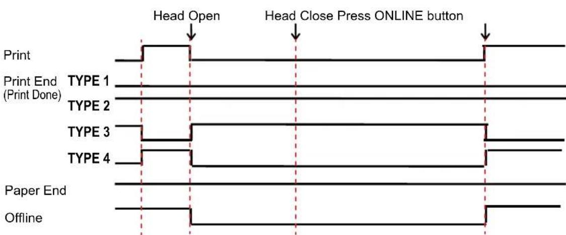 |
- When RFID Mode is enabled (CL4NX only)
| Item | Output Waveform |
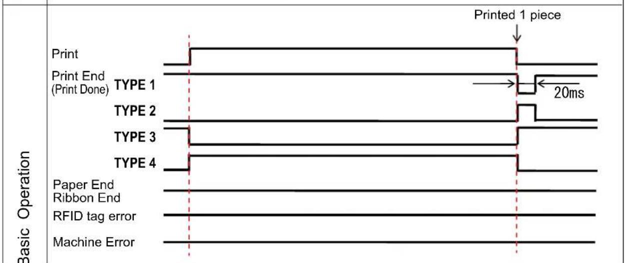 | |
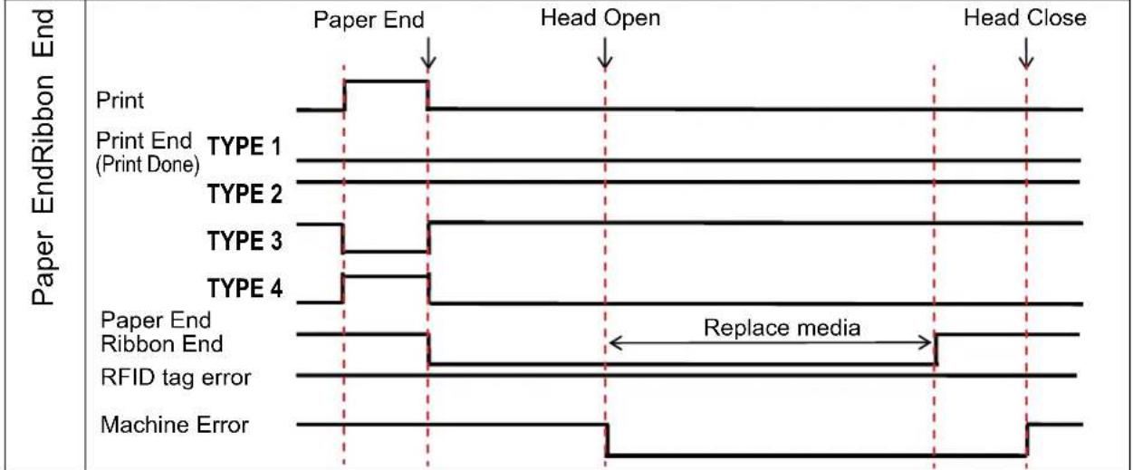 | |
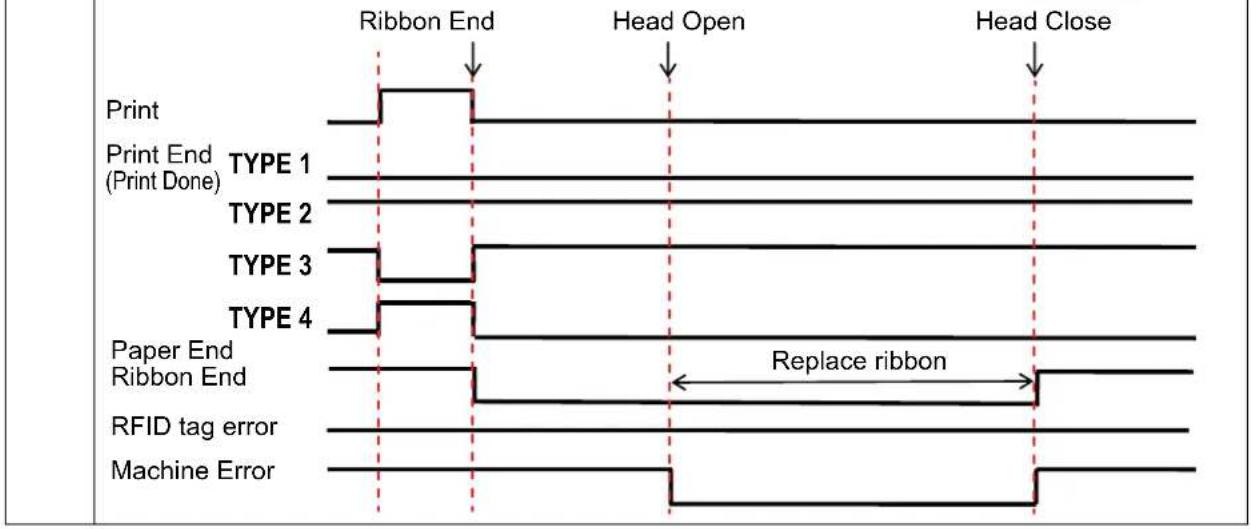 |
Timing Chart (Wait signal for dispense completion)
| Item | Output Waveform | |
| After Print | Printed 1 piece Dispense Complete | |
| Print End (Print Done) TYPE 1 TYPE 2 TYPE 3 TYPE 4 Wait for dispense completion | 20ms | |
| Backfeed Before Print Backfeed | Printed 1 piece Dispense Complete | |
| Print End (Print Done) TYPE 1 TYPE 2 TYPE 3 TYPE 4 Wait for dispense completion | 20ms | |
7.7.7 Wireless LAN Interface
This interface complies with the IEEE802.11a/b/g/n standard.

CAUTION
Before using wireless LAN near medical devices and facilities, consult your system administrator.
| Basic Specifications | |
| Protocol Status3, Status4, Status5 | |
| IP Address IPv4 | IPv6 |
| Subnet Mask IPv4 | IPv6 |
| Gateway Address IPv4 | IPv6 |
| Data Transfer Method 802.11a | max 54 Mbps802.11n: max 135 Mbps802.11b: max 11 Mbps802.11g: max 54 Mbps |
| NoteThese are the logical values based on the wireless LAN specifications and are not the actual data transfer speeds. | |
| Frequency Band 2.4 GHz (2.4) | 2 to 2.485 GHz)5 GHz |
| Communication Channel The number of channels you can set varies depending on the region where you use the printer. | |
| SSID Any alphanumeric character (maximum 32) | |
| Authentication Open System | Shared KeyWPA/WPA2Perform the RADIUS server authentication using 802.1x (EAP-TLS, LEAP, EAP-TTLS, EAP-PEAP, EAP-FAST protocol) |
| Encryption None | WEP (64 bits/128 bits)AES (WPA-PSK/WPA2-PSK, WPA-802.1x/WPA2-802.1x authentication) |
| Communication Mode Infrastructure | Ad Hoc |
| Software Specifications | |
| Supported Protocol TCP/IP | |
| Network Layer IP, ICMP | |
| Session Layer TCP | |
| Application Layer LPD, FTP, D | HCP, HTTPS, SNMP, NTP |

natural_image
World map illustration showing continents and oceans (no text or labels)Extensive contact information for worldwide SATO operations can be found on the Internet at www.satoworldwide.com