SRM910-33ECN - Fireplace SYLVANIA - Free user manual and instructions
Find the device manual for free SRM910-33ECN SYLVANIA in PDF.

User questions about SRM910-33ECN SYLVANIA
0 question about this device. Answer the ones you know or ask your own.
Ask a new question about this device
Download the instructions for your Fireplace in PDF format for free! Find your manual SRM910-33ECN - SYLVANIA and take your electronic device back in hand. On this page are published all the documents necessary for the use of your device. SRM910-33ECN by SYLVANIA.
USER MANUAL SRM910-33ECN SYLVANIA
natural_image
Exterior view of a portable gas stove with visible flames and wood shavings (no text or symbols)SYLVANIA is a registered trademark of OSRAM SYLVANIA, used under license.
iMPOrtaNt: PIEaSE Note WHEN yOu OPEN the CartON CarEFully CHECK tHE uNit aND MaKE SurE tHReE is NO DaMaGE. if yOu Have aNy PrOBIEMS With aSSEMBING the uNit, With HOW THE VariOuS FuNCtIONS WORk Or With DaMaGE Or Missing PartS PIEaSE Call 1-800-459-4409 (EST) iIMMEDatEly For SErVice.
NOTE: DO NOT rEturN uNit to THE StOrE BEFOrE CalliNG the toll FrEE NuMBEr.
Do not dispose of your cartons until you are completely satisfied with your new fireplace heater.
NOTE: Light bulbs may become loose during shipping. If the flame effect is dim or does not work, please check that light bulb or bulbs are finger tight in socket. See instructions for replacing bulb or bulbs.
INSTRUCTION MANUAL
attENTION:
- Find a location for the fireplace heater that is protected from direct sunlight.
- Do not plug the unit into the power outlet before reading all instructions.
SAVE THESE INSTRUCTIONS FOR FUTURE USE
IMPORTANT SAFETY INSTRUCTIONS
WHEN uSING ELECTriCal aPPIaNCES, BaSiC PrECAutiONS SHOuID alWayS BE FOLLOWED TO rEDuCE THE rISK OF FirE, ELECTriC SHOCK, aND iNJury to PErSONS, iNCiuDiNG THE FOLLOWING:
1) Read all instructions before using this electric fireplace heater.
2) This electric fireplace heater is hot when in use. To avoid burns, do not let bare skin touch hot surfaces. The grill directly in front of the heater outlet becomes hot during heater operation. Keep combustible materials, such as furniture, pillows, bedding, papers, clothes, and curtains at least 3 feet (0.9 m) away from the front of the unit and keep them away from the sides and rear.
3) Extreme caution is necessary when any heater is used by, or near, children or individuals with disabilities and whenever the fireplace is left operating and unattended.
4) Always unplug fireplace when not in use.
5) Do not operate any electric fireplace with a damaged cord or plug or after the heater malfunctions, has been dropped or damaged in any manner.
6) Do not use outdoors.
7) This electric fireplace heater is not intended for use in bathrooms, laundry areas and similar indoor locations. Never locate heater where it may fall into a bathtub or other water container.
8) Do not run cord under carpeting. Do not cover cord with throw rugs, runners, or similar coverings. Arrange cord away from traffic area and where it will not be tripped over.
9) To disconnect fireplace, turn controls to off, then remove plug from outlet.
10) Connect to properly grounded outlets only.
11) Do not insert or allow foreign objects to enter any ventilation or exhaust opening as this may cause an electric shock or fire, or damage the heater.
12) To prevent a possible fire, do not block air intakes or exhaust in any manner. Do not use on soft surfaces, like a bed, where openings may become blocked.
13) A heater has hot and arcing or sparking parts inside. Do not use it in areas where gasoline, paint, or flammable liquids are used or stored.
14) Use this fireplace heater only as described in this manual. Any other use not recommended by the manufacturer may cause fire, electric shock, or injury to persons.
15) Avoid the use of an extension cord because the extension cord may overheat and cause a risk of fire. However, if you have to use an extension cord, the cord shall be No.16AWG minimum size and rated not less than 1875 watts.
16) Caution: Do not plug this product into a receptacle controlled by a wall switch or dimmer.
17) When storing or transporting the unit and cord, keep in a dry place, free from excessive vibration and store so as to avoid damage.
CautiON:
IF yOu uSE this HEaEr iN CONJuCtION WitH a tHERMal CONtr0I, a ProGRAm CONtr0IIer, a tiMEr Or aNy OtHEr DEVICE that SWitCHES the HEaEr ON autOMatiCally, rEMEMBER to OBSErVE all SaFEty WarNiINGS at all tiMES. the FirEPIaCE HEaEr HaS SaFEty OVERHeat PrOtECTION. if THE OVERHeat PrOtECTION triPS, SWitCH OFF all SWitCH ButtONS and Wait aPPROXIMatEly 5 -10 MiNutES. it SHouID RESEt autOMatiCally ONCE the uNit COOIS DOWN.
Warning:
Procedures and techniques if not carefully followed will result in damage to the equipment and will expose the user to the risk of serious injury, illness or death.
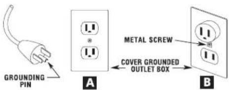
This electric fireplace heater is for use on 120 volts. The cord has a plug as shown at A in illustration below. An adapter as shown at C is available for connecting three-blade grounding-type plugs to two-slot receptacles. The green grounding plug extending from the adapter must be connected to a permanent ground such as a properly grounded outlet box. The adapter should not be used if a three-slot grounded receptacle is available.
A 15 AMP circuit is required to operate this heater. If the breaker trips when the heater is used then you may need to move the heater to another location or unplug other appliances that are on the same circuit. If you require an extension cord use one that is rated at 1875 watts.
ASSEMBLY INSTRUCTIONS
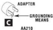
PartS liSt:
Fireplace insert....1
A) Top panel.... 1
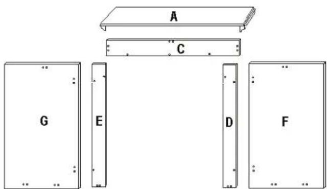
B) Base panel....1
C) Upper front panel 1
D) Left front panel....1
E) Right front panel.... 1
F) Left side panel....1
G) Right side panel....1
S) Wood connectors....8
T) Short KD screws 5
U) Mounting Clips 3
V) Mounting Brackets.... 2
W) KD screws.... 45
X) Plastic Connectors.... 13
Y) SELF REPAIR SET
Touch-up repair paint (bottle)
L-shape bracket.... 2
Screws for L bracket....8
Plastic connectors....1
KD screws 3
KD nuts.... 3
Z) WALL ANCHOR SAFETY CABLE
Wall anchor 1
Screw for wall anchor 1
Screw for mantle....1
Safety cable 1
This fireplace mantel requires 1 - 2 people to assemble and normally takes 45 minutes - 1 hour to complete.
TOOL REQUIRED: PHILLIPS HEAD SCREWDRIVER
natural_image
Simple 3D diagram of a rectangular block with labeled point B and scattered dots (no text or symbols beyond label)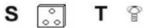

MANTEL ASSEMBLY
CAUTION: Place a piece of cardboard or protective sheet on the floor in order to avoid scratching the decorative surface of your mantle during assembly. Please DO NOT fully tighten the KD screws until all panels are assembled.
NOTE: Each Plastic Connector is pre-assembled (pre-drilled) on the specific panels with 2 screws. If the KD screw(s) do not fit during assembly, loosen the 2 (pre-drilled) screws to adjust the Plastic Connector until the KD screws are able to be installed. Tighten all KD screws once all panels are assembled.
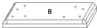
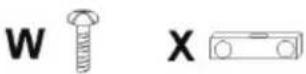
Step 1: Attach 13 Plastic Connectors [X] to Panel C, D E, F and G with 26 KD screws as shown in Fig. A. (2 KD screws for each plastic connector). Attach 2 Wood Connectors [S] to Panel C with 4 KD screws (2 KD screws for each wood connector).
natural_image
Technical line drawing of a mechanical assembly with multiple views and mounting brackets (no text or symbols)Fig. A
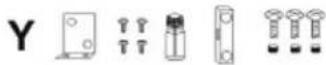
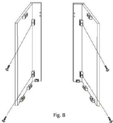
Step 2: Attach Left front panel [D] to Left side panel [F] with 2 KD screws. Attach Right front panel [E] to Right side panel [G] with 2 KD screws. See Fig. B.
natural_image
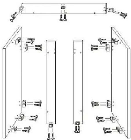
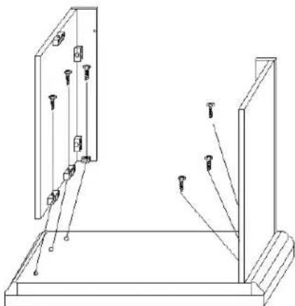
Technical line drawing of two identical mechanical components with mounting holes and connecting rods, labeled Fig. B (no text or symbols on the components themselves)Step 3: Attach Left front panel [D] and Left side panel [F] to Base [B] with 3 KD screws. Attach Right front panel [E] and Right side panel [G] to Base [B] with 3 KD screws. See Fig. C.
natural_image
Technical line drawing of two mechanical components with mounting holes and connecting rods (no text or symbols)Fig. C
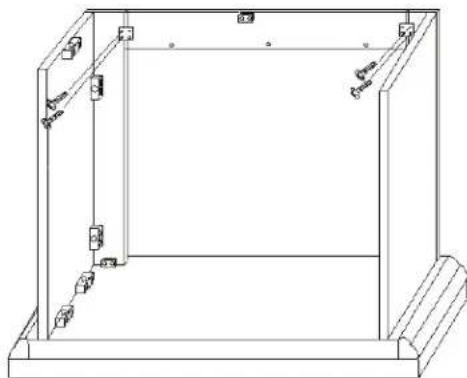
Step 4: Attach Upper front panel [C] to Left and Right front panel [D and E] with 4 KD screws. See Fig. D.
natural_image
Technical line drawing of a rectangular frame with internal components and mounting points (no text or symbols)Fig. D
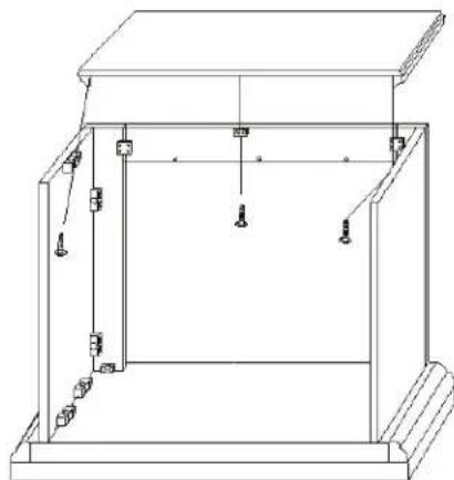
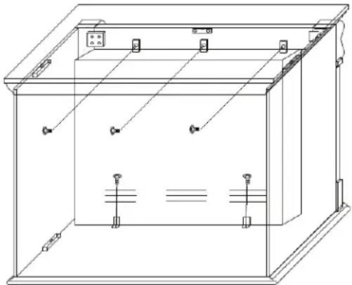
Step 5: Attach Top panel [A] to the unit as shown in Fig. E with 3 KD screws. See Fig. E.
natural_image
Technical line drawing of a mechanical assembly with no visible text or symbolsFig. E
Step 6: Tighten all KD SCREWS.
FIREPLACE INSERT INSTALLATION
The fireplace insert can be installed after the mantel has been fully assembled.
WARNING: Make sure the fireplace insert controls are in the OFF position and the unit is NOT plugged in.
Step 1: Carefully place the INSERT in the unit opening. The front of INSERT should be flush with the front of the mantel. Carefully lift the INSERT into the mantel until the top stopper is against the mantel.
Step 2: Attach 3 Mounting Clips [U] to the top side of insert with 3 Short KD screws [T]. Attach 2 Mounting Brackets [V] to the bottom of insert with 2 Short KD screws [T]. See Fig F.
natural_image
Technical line drawing of a cabinet or enclosure with internal components and wiring (no text or symbols)Fig. F
Step 3: Move assembled unit to desired location. Unit should not be positioned in area exposed to direct sunlight.
OPERATION
After reading complete instructions, confirm all controls on fireplace are in the OFF position. Plug the fireplace into a 15AMP/120Volt outlet. If the cord does not reach, you may use an extension cord rated for a minimum of 1875 WATTS. Once the fireplace insert has been properly connected to a grounded electrical outlet, it is ready to operate.
The controls are located behind the 2 front covers at the top right and left corners of the insert, and can be accessed by gently pushing the bottom of the covers.
natural_image
Line drawing of a portable air conditioner unit with two wheels and control panel (no text or symbols)O/I: Press this button for main power and flame effect. The indicator light will turn on. See below for other control switches.
750W: For low heat function - Press this switch while the 0/1 switch is in the on position for low heat. The indicator light will turn on.
1500W: For high heat function - Press this switch while the O/I switch and the 750W switch are in the on position for high heat. The indicator light will turn on.
Temperature Control: To adjust the temperature to your individual requirements, turn the temperature control dial to the right (clockwise) to increase the desired temperature and to the left for lower temperature. This temperature control dial can only be used while the O/I switch and 750W & 1500W switches are in the ON position.
Dimmer Control Knob: Turn the dimmer dial clockwise or counter clockwise to get the desired flame intensity. The dimmer switch can only be used when the O/I switch is in the on position.
Note: When the O/I switch is turned off, all other heater functions will stop even though the switches may be in the on position.
MAINTENANCE
Disconnect power and unplug the power cord before attempting any maintenance or cleaning to reduce the risk of fire, electric shock or damage to persons. The bulbs in your unit can become extremely hot. Allow at least 10 minutes between turning off the unit and removing the light bulbs to avoid the accidental burning of the skin.
riSK OF FirE: DO NOT EXCEED the rECOMMENDED BulB WattaGE.
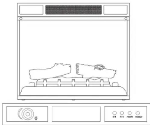
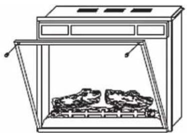
REPLACING THE FLAME EFFECT LIGHT AND LOG-SET LIGHT BULBS
Step 1: Remove the 2 screws on the front of the fireplace and open the glass window.
Step 2: Remove the screws from both sides of the log set bed.
Step 3: Remove the log set bed. You will find 2 x 40 Watt type E-12 bulbs.
Step 4: Loosen, remove and replace the burnt out bulb(s)
Step 5: Set the log set bed back into place and re-attach the screws.
Step 6: Close the glass window and re-attach the screws.
Step 7: Plug in the unit.
natural_image
Line drawing of a simple kitchen appliance with two food items inside (no text or symbols)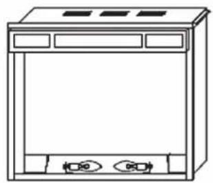
natural_image
Line drawing of a front-loading cabinet with two buttons and ventilation grilles (no text or symbols)
REPAIR SET
natural_image
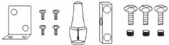
Technical line drawings of mechanical components including a bracket, screw fasteners, a handle, and multiple bolts (no text or symbols)TOUCH-UP REPAIR PAINT
- Paint directly on the mantel unit if necessary. Fig. A
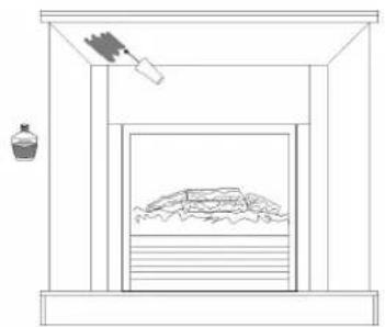
natural_image
Simple line drawing of a room with a stove, a bottle, and a tray (no text or symbols)Fig. A
REPAIRS
If any problems are found with the original parts during mantel assembly such as the panels cannot be installed with the plastic connector. Try to solve by one of the following method.
Tools required: Electric drill, drill bits 3/4 inches (10 mm) or 1/16 inches (2 mm), pencil, hammer, Philips screwdriver, safety goggles and gloves (if necessary).
WarNiNG: Wear goggles before you start drilling.
OPTION 1:
Use the spare KD NUTS, KD SCREWS and PLASTIC CONNECTOR
- Place the PLASTIC CONNECTOR on the mantel unit and mark the drill-holes as shown in Fig. B.
natural_image
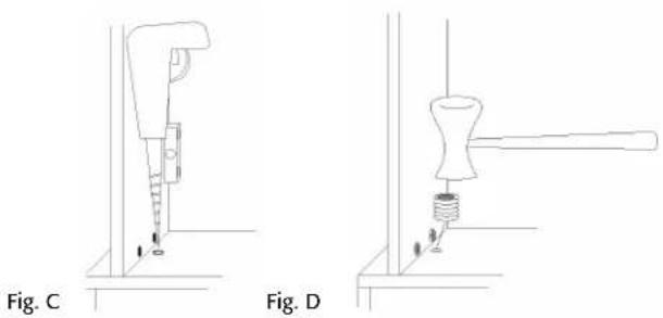
Technical line drawing of a mechanical or electrical enclosure with an inset showing a vertical component and a magnified detail (no text or symbols)- Drill the holes with diameter 3/4 inches (10 mm) and depth 3/4 inches(10mm) on the mantel. Each Plastic Connector needs 3 holes. See Fig. C.
-
Gently install the KD NUTS into the drilled-holes with hammer as shown in Fig. D.
-
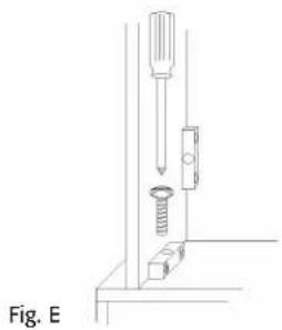
Attach the PLASTIC CONNECTOR and lock in place with KD SCREWS as shown in Fig. E.
natural_image
Technical line drawing of a mechanical assembly with a screw and spring (no text or symbols)OPTION 2:
Use the SMALL L-BRACKETS and SCREWS.
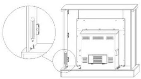
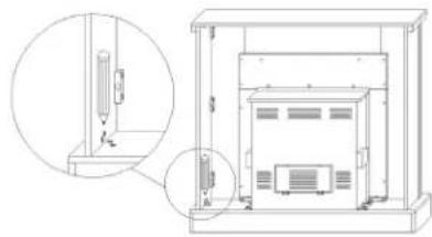
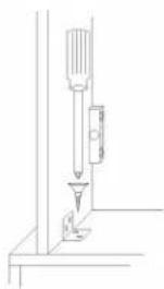
- Place the SMALL L-BRACKET to the unit as shown and mark the drill-holes on the mantel as shown in Fig. F.
natural_image
Technical line drawing of a mechanical or electrical enclosure with zoomed-in detail (no text or symbols)Fig. F
- Drill the holes with diameter 1/16 inches (2 mm) and depth 5/16 inches (8mm) on the mantel. Each SMALL L-BRACKET needs 4 holes. See Fig. G.
Fig. G
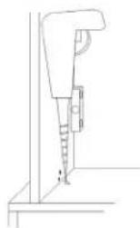
Fig. H
natural_image
Technical line drawing of a mechanical assembly with a tool and base (no text or symbols)- Attach the SMALL L-BRACKET and lock in place with SCREWS as shown in Fig. H
CLEANING
To clean unit first turn off controls on unit and unplug the unit from power source. To clean glass display panel; remove dust with clean dry cloth or to remove finger prints and other marks clean glass with clean damp cloth. Do not use abrasive cleaners or spray liquids on glass display panel surface. Metal and metal painted parts should be cleaned with damp cloth. Do not use abrasive cleaners or spray liquids on these surfaces.
WARRANTY
Every electric fireplace heater is tested before it leaves the factory and it is guaranteed for one year. If the unit should fail to operate correctly within one year from the date of purchase, call customer service at 1-800-459-4409 (EST). We will, at our discretion either repair or replace the unit. It will have to be returned to us freight prepaid and we will return the repaired or replaced unit to you freight prepaid. The company's sole obligation is to repair or replace the unit.
This warranty is void if in the opinion of Quality Craft the unit has been tampered with, altered, misused, damaged, abused or used with the wrong power source. Light bulbs and remote batteries are not covered by this warranty. The warranty is for homeowner use only and does not cover units used in commercial situations.
Imported by
Quality Craft
Laval, Quebec, Canada H7S 2G7
1-800-459-4409 (EST)
www.qualitycraft.com
Made in China