
PAR3115 - Kitchen sink RANGEMASTER - Free user manual and instructions
Find the device manual for free PAR3115 RANGEMASTER in PDF.


| Brand | Rangemaster |
| Model | PAR3115 |
| Product Type | Kitchen Sink |
| Material | Stainless Steel |
| Finish | Satin Brush |
| Number of Bowls | 1 |
| Overall Dimensions (L x W x D) | Approx. 780 x 510 x 200 mm |
| Cutout Dimensions (L x W) | Approx. 750 x 480 mm |
| Bowl Depth | 200 mm |
| Weight | Approx. 12 kg |
| Drain Position | Center |
| Drain Size | 90 mm (standard) |
| Installation Type | Top-mount or undermount (cutout required) |
| Included Accessories | Drainer basket, mounting clips, template |
| Care Instructions | Clean with mild soap and soft cloth; avoid abrasive cleaners |
| Warranty | Limited lifetime warranty |
| Compliance | Meets relevant safety standards |
| Spare Parts Available | Replacement drain kits, strainers, mounting hardware |
Frequently Asked Questions - PAR3115 RANGEMASTER
User questions about PAR3115 RANGEMASTER
0 question about this device. Answer the ones you know or ask your own.
Ask a new question about this device
Download the instructions for your Kitchen sink in PDF format for free! Find your manual PAR3115 - RANGEMASTER and take your electronic device back in hand. On this page are published all the documents necessary for the use of your device. PAR3115 by RANGEMASTER.
USER MANUAL PAR3115 RANGEMASTER
IGNEOUS GRANITE SINKS
Installation Instructions &
Aftercare Information

Instructions for:
Top Mounted Sinks - Amethyst & Magma
Undermount Sink - Paragon
Fig.1

Fig.2
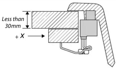
Fig.3
natural_image
Line drawing of a hand holding a pen writing on a notepad (no text or symbols present)Fig.4
Worktop
Worktop

| Name | Length (mm) | Width (mm) | Corner Radius (mm) |
| Magma 1.0 | 980 | 480 | 10 |
| Magma 1.5 | 980 | 480 | 10 |
| Amethyst 1.5 | 980 | 480 | 10 |
| Amethyst 1.0 | 840 | 480 | 10 |
| Paragon 1.5 | 520 | 400 | 30 |
Table 1
Installer
Please leave this leaflet with the user, as it contains valuable after care advice.
Notes
During installation, take care to protect the sink from scuffs and scratches.
Do not stand on the sink.
During installation, do not stand the sink on its edges or corners. This may cause damage.
Avoid straining and over tightening of all plumbing fixtures connected to the sink.
Carefully check that the moulding and edges of the sink are dead level so that water will flow off the drainer.
The clamping brackets are suitable for worktops of between 30–40 mm thickness (Fig.1). If your worktop is a different size then it may require packing under the clamps or rebating (Fig.2).
Preparing the Worktop
Marking Out the Opening
We recommend that you fit the sink to the worktop before permanently fixing the worktop to the cabinet.
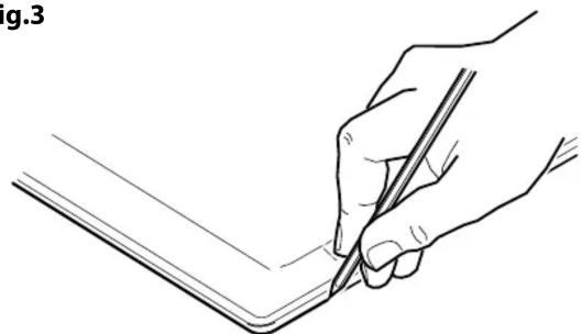
- Place the sink upside down on the worktop. Position the sink on the worktop as required. Make sure the cabinet framework will clear all parts of the sink. Using a soft, sharp pencil draw around the sink as accurately as possible (Fig.3). Remove the sink.
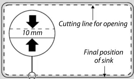
- Draw another line 10 mm inside the sink top outline – this is the cutting line for the opening (Fig.4).
- Drill as large a hole as possible inside the cutting line. Using a pad saw, jigsaw or similar, cut out the opening up to the cutting line.
Alternatively, you can use the sink template (if supplied) or the figures given in Table 1.
Sealing the Edges of the Opening.
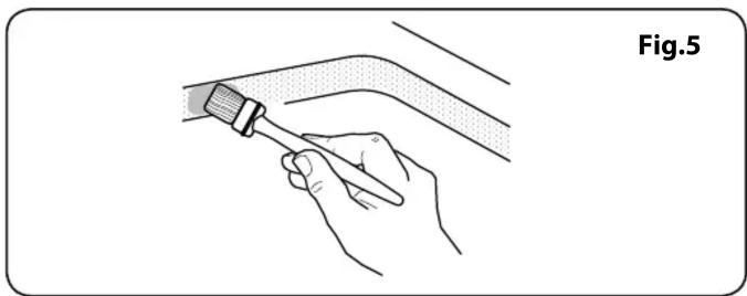
We recommend that porous edges around the cut-out are sealed using a waterproof sealant such as varnish, paint or wood glue. This will prevent swelling of the worktop should any small leaks occur (Fig.5).
Preparing the Sink
Tap Hole Preparation (Amethyst & Magma only)
Tap hole locations are part cut into the underside of the sink. The upper section of the tap hole will have to be knocked out. ALWAYS knock out from the top of the sink and NOT the underside, this may damage the front top surface of the sink. After deciding which tap hole to use, mark the location of the tap hole centre onto the front face of the sink using a soft pencil (This may already be marked with a coloured adhesive dot). The area around the rear of the tap hole will require support. Place the tip of a screwdriver or similar tool on the marked position, ensuring that the shaft of the screwdriver is at 90° to the sink surface (NOT angled). Strike the screwdriver
with a hammer. The upper section of the tap hole should knock out.
The tap hole will have rough edges. Use a suitable rasp to smooth the edges of the hole. Always work towards the sink surface avoiding upward strokes that may chip the sink surface.
For fittings with a larger shaft diameter than 35 mm, the pre-drilled holes must be enlarged. Use a fret saw with a metal cutting saw and enlarge the hole as shown in Fig.6. Then carefully remove the 'teeth' with pliers. Do not use force!
Drilling a Hole for Soap Dispensers or Other Devices.
Before drilling please read safety instructions supplied with hole saw.
The front face must be fully supported to prevent cracking when drilling or cutting.
WARNING!
Any machining operation will produce fine particles of dust. Drilling or cutting MUST be carried out in a well-ventilated area.
If a hole is required, but has not been supplied in the sink, proceed as follows:
- Decide whether the bowl is to be left or right handed when the sink is fitted. You will require a 35 mm diamond tipped hole saw (not supplied).
- Using a 35 mm hole saw, carefully cut out the tap hole (Fig.7).
Clip Preparation
There are three methods of clip fitting covered in this guide. Only one will be supplied with each sink:
- Screw down fixing (Amethyst 1.5)
• Pin fixing (Amethyst 1.0, Magma 1.0, Magma 1.5) - Screw down 'U' clamps (Paragon)
Screw Down Fixing (Amethyst 1.5)
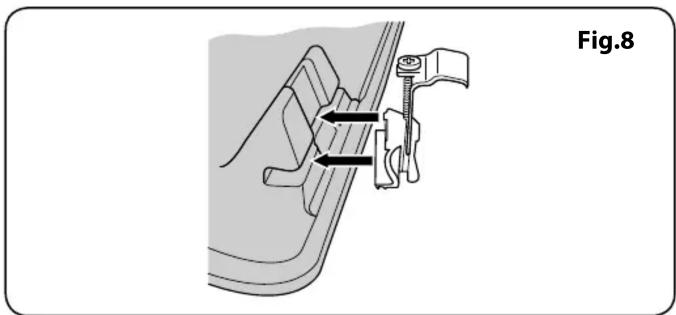
- Locate the clamps then give a gentle tap to secure in the slot (Fig.8).
- Hinge the clamps away from the sink edge.
Pin Fixing (Amethyst 1.0, Magma 1.0, Magma 1.5)
Important: The clamps are designed to be fitted once. Ensure that the clamps are facing the correct way before securing in place. Removal will not be possible once fitted.
- Position the clamps over the holes in the sink. Push the clamps down ensuring that the base of the clamps are flat against the sink surface. If a clip is tight then, using a flat screwdriver, tap on the base until it snaps into place.
- Tap the pins on the clamps until the ends of the pins are level with the top edge of the clamps (Fig.9).
- Hinge the clamps away from the sink edge.
Screw Down 'U' Clamps (Paragon 1.5)
- Drill four 8 mm holes as in Fig.10.
- Tap in the four metal inserts supplied. Additionally, Epoxy resin adhesive may be required on particleboard worktops. Do not fit the 'U' clamps at this point.
natural_image
Illustration of a hand using a tool to adjust or install a component, labeled Fig.5 (no text or symbols on the diagram itself)
natural_image
Circular diagram with evenly spaced radial segments, labeled Fig.6 (no text or symbols within the diagram itself)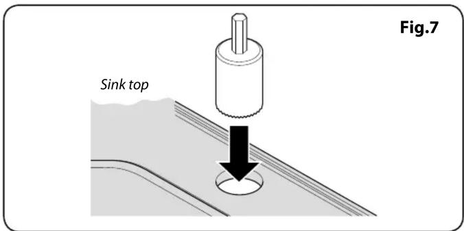
natural_image
Mechanical assembly diagram showing a clamp or bracket with directional arrows, labeled Fig.8 (no text or symbols on the diagram itself)
natural_image
Mechanical assembly diagram showing a component being inserted into a housing, with arrows indicating direction (no text or symbols present)
Fig.11
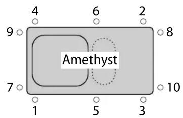


Fig.12

natural_image
Technical line drawing of a mechanical clamp or bracket component (no text or symbols)25 Year Guarantee
We guarantee to replace any igneous granite sink that breaks due to material or manufacturing defects within 25 years from the date of purchase.
The guarantee does not cover normal wear and tear occurring through use of the product.
For the guarantee to apply the owner must follow the use, care and cleaning instructions provided.
Accessories and waste fittings are not included in this guarantee.
CE
RANGEmaster
Meadow Lane, Long Eaton,
Nottingham, NG10 2GD, England
Tel: +44 (0) 115 946 4000 Fax: +44 (0) 115 973 6602
E-mail: consumers@rangemaster.co.uk
www.rangemaster.co.uk
13
EN 13310:2003
Kitchen sink made of: Igneous Granite / Composite
Cleanability: Pass
Load resistance: NPD / N/A
Durability: Pass
Waste Fittings
Fit the waste fittings to the sink using the instructions supplied with them.
Applying the Silicon Sealant
DO NOT use Epoxi sealant or Epoxi adhesive.
Top Mounted Sinks (Amethyst & Magma)
Apply silicon sealant (not supplied) to the underside of the sink rim.
Undermount Sink (Paragon)
Apply silicon sealant (not supplied) to the underside rim of the worktop opening.
Fitting the Sink
Top Mounted Sinks (Amethyst & Magma)
-
Turn the sink upside down and lay the worktop over the sink. Swing each clip into place – this is the most effective method, although if the worktop has been fitted to the cabinet the sink can be placed in the opening and fixed in position from underneath.
-
Centre the sink. Tighten the fixing screws in the sequence shown in Fig.11.
! DO NOT tighten fully at first attempt.
Remove any surplus sealing material or wipe away any excess sealant.
Undermount Sink (Paragon)
-
The worktop should already be upside down with silicon sealant in place. Lay the sink on to the worktop. Fit the 'U' clamps into place using the screws supplied (Fig.12) – this is the most effective method, although if the worktop has been fitted to the cabinet the sink can be fixed in position from underneath.
-
Centre the sink. Tighten the fixing screws in the sequence shown in Fig.11.
A DO NOT tighten fully at first attempt.
Remove any surplus sealing material or wipe away any excess sealant.
After Care
Day-to-day care
Although your sink is made from extremely durable materials and will withstand a great deal of hard use, it can be scratched by hard or sharp objects. If the surfaces are to be kept in a blemish free condition reasonable care should be taken when handling such items.
DO NOT use the drainer as a chopping board.
Cleaning
DO NOT use abrasive cleaning creams or powders, concentrated caustic soda, formic acid or anything highly corrosive.
DO NOT attempt to remove limescale by scraping it off.
Please refer to www.rangemaster.co.uk for a full guide to cleaning your sink.


- IGNEOUS GRANITE SINKS
- Installation Instructions &
- Aftercare Information
- Installer
- Notes
- Preparing the Worktop
- Marking Out the Opening
- Sealing the Edges of the Opening.
- Preparing the Sink
- Tap Hole Preparation (Amethyst & Magma only)
- Drilling a Hole for Soap Dispensers or Other Devices.
- Clip Preparation
- Screw Down Fixing (Amethyst 1.5)
- Pin Fixing (Amethyst 1.0, Magma 1.0, Magma 1.5)
- Screw Down 'U' Clamps (Paragon 1.5)
- Year Guarantee
- CE
- RANGEmaster
- Waste Fittings
- Applying the Silicon Sealant
- Top Mounted Sinks (Amethyst & Magma)
- Undermount Sink (Paragon)
- Fitting the Sink
- After Care
- Day-to-day care
- Cleaning
Brand : RANGEMASTER
Model : PAR3115
Category : Kitchen sink