RC500 - Receiver PRESONUS - Free user manual and instructions
Find the device manual for free RC500 PRESONUS in PDF.

| Product Type | Remote Control |
| Dimensions | 1.75" H x 19" W x 6" D (1U rackmount) |
| Weight | 2.5 lbs (1.13 kg) |
| Power Supply | Power over Ethernet (PoE) or 12V DC adapter |
| Connectivity | Ethernet (RJ45) |
| Controls | 8 motorized faders, 8 mute, 8 solo, 8 select buttons |
| Display | Backlit LCD |
| Mounting | Rackmount ears included |
| Compatibility | PreSonus StudioLive Series III mixers |
| Operating Temperature | 32°F to 104°F (0°C to 40°C) |
| Included Accessories | Ethernet cable, rackmount screws, quick start guide |
| Warranty | 2 years limited |
| Maintenance | Clean with dry cloth; avoid moisture |
| Safety | Use only provided power supply |
| Spare Parts | Contact PreSonus customer support |
| Repairability | Do not attempt self-repair |
| General Information | Part of PreSonus ecosystem |
Frequently Asked Questions - RC500 PRESONUS
User questions about RC500 PRESONUS
0 question about this device. Answer the ones you know or ask your own.
Ask a new question about this device
Download the instructions for your Receiver in PDF format for free! Find your manual RC500 - PRESONUS and take your electronic device back in hand. On this page are published all the documents necessary for the use of your device. RC500 by PRESONUS.
USER MANUAL RC500 PRESONUS
Channel Strip with Solid-State Preamp, Compressor, and EQ
Owner's Manual
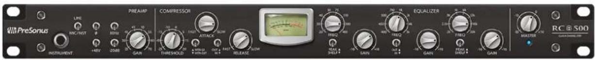
Table of Contents
1 Overview — 1
1.1 Introduction — 1
1.2 Summary of RC 500 Features — 1
1.3 What's in the Box — 2
2 Hookup — 3
2.1 Input Controls — 3
2.2 Compressor Controls — 4
2.3 EQ Controls — 5
2.4 VU Meter and Controls — 6
2.5 Master Control — 6
2.6 Physical Connections — 6
2.7 Hookup Diagrams — 8
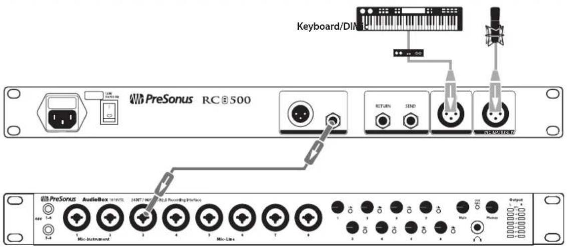
2.7.1 Basic Recording Diagram — 8
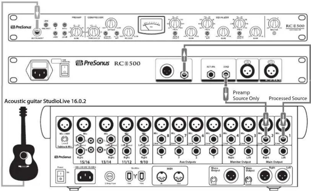
2.7.2 Advanced Recording Diagram — 8
3 Tutorial — 9
3.1 A Brief Tutorial on Dynamics Processing — 9
3.1.1 Common Questions Regarding Dynamics Processing — 9
3.2 Equalizers — 11
3.2.1 What is an EQ? — 11
3.2.2 Equalization Settings: How to Find the Best and Leave the Rest — 12
3.2.3 EQ Frequency Charts — 12
4 Resources — 15
4.1 Audio Specifications — 15
4.2 RC 500 Block Diagram — 16
4.3 RC 500 Recall Sheet — 17
4.4 Troubleshooting — 18
4.5 Warranty — 19
1 Overview
1.1 Introduction

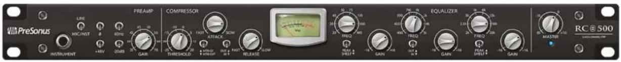
Thank you for purchasing the PreSonus® RC 500. PreSonus Audio Electronics, Inc., has designed the RC 500 utilizing high-grade components to ensure optimum performance that will last a lifetime. The RC 500 is a professional channel strip that includes a Class A solid-state preamplifier with a unique hybrid design that combines the latest generation of low-distortion operational amplifiers and low-noise, discrete transistors. This design maintains the sonic qualities of Class A circuitry and benefits from the operational amplifier's characteristic repeatability in performance.
The Class A preamp is combined with the same FET-based compressor and semi-parametric equalizer circuits found in the PreSonus ADL 700, making the RC 500 an excellent choice for professional studio applications. Great for use with all types of microphones and instruments, the RC 500 has the sonic power and flexibility to achieve luscious vocals, crystal-clear acoustic guitars, fat bass guitars, dynamic acoustic piano, cracking snares, and much more.
We encourage you to contact us with questions or comments regarding this product. You can reach us by email at support@presonus.com or call us at 1-225-216-7887 between 9 a.m. and 5 p.m. U.S. Central Time. PreSonus Audio Electronics is committed to constant product improvement, and we value your suggestions highly. We believe the best way to achieve our goal of constant product improvement is by listening to the real experts: our valued customers. We appreciate the support you have shown us through the purchase of this product and are confident that you will enjoy your RC 500!
ABOUT THIS MANUAL: We suggest that you use this manual to familiarize yourself with the features, applications, and correct connection procedures for the RC 500 before connecting it to the rest of your studio gear. This will help you avoid problems during installation and setup.
Throughout this manual you will find Power User Tips that can help make you an RC 500 expert. In addition, tutorials covering the basics of dynamics processing and equalization can be found in Section 3 of this manual.
1.2 Summary of RC 500 Features
•Transformer-coupled, high-gain microphone preamp
•Class A hybrid design with minimal signal path
- Unbalanced 14 " TS Instrument input on front panel
•Balanced XLR Microphone and Line inputs on rear panel - Input Select switch
•FET based compressor using hybrid detection methods, with switching relays for hard bypass
• 3-band semi-parametric equalizer with switching relays for hard bypass
•+48V phantom power, 80 Hz rolloff, and -20 dB pad
•High-grade components
•Film capacitors
•1% tolerance resistors
•Low-distortion op amps
1.3 What's in the Box
• VU meter with selectable Output Level and Gain Reduction display
•Master Fader output control
•Balanced Send and Return signals
- Balanced line-level output on XLR and 14 " TRS connectors
•Internal toroidal power supply
•Steel chassis
1.3 What's in the Box
In addition to this manual, the RC 500 package contains the following:

•PreSonus RC 500 Channel Strip
•IEC power cable
2 Hookup
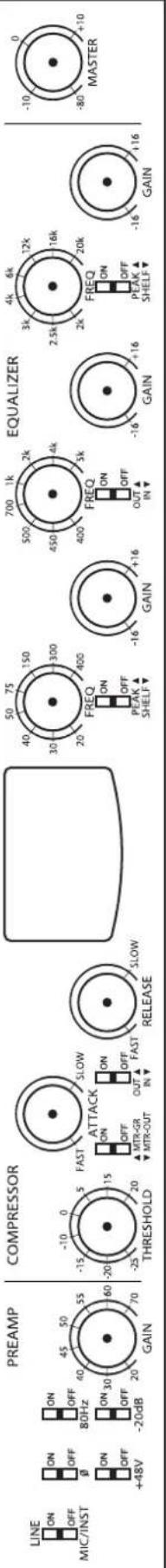
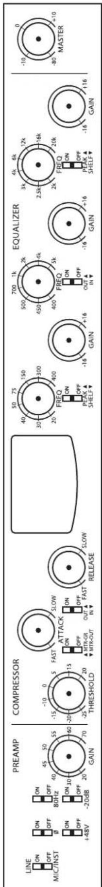
2.1 Input Controls
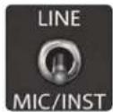
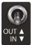
Input Source Select. The input Source Select switch allows you to choose between the signal sources connected to the RC 500 inputs. It patches the selected input through the signal chain, completely bypassing the other inputs.
Power User Tip: The Instrument input is normalled through the Microphone input and will take precedence when both inputs are in use. Because of this, you can leave your favorite mic and line-level source connected all the time and quickly patch in an instrument via the front panel when necessary.
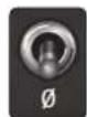
Polarity Invert. Reverses the polarity of the signal.
Power User Tip: Use Polarity Invert when recording with more than one open microphone to combat phase cancellation between microphones.
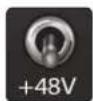
+48V. The 48 volt phantom power supplied by the XLR input on the rear panel provides power for condenser microphones and other devices requiring continuous power. This power is supplied at a constant level to prevent signal degradation.
WARNING: In general, phantom power is only required for condenser microphones and can severely damage some dynamic microphones, especially ribbon mics. Therefore, switch phantom power off when not required by the device connected to the XLR input. Consult the documentation that came with your microphone to verify its phantom power requirements.
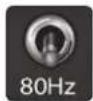
80 Hz Rolloff. Your RC 500 is equipped with a High Pass Filter. The 80 Hz switch engages this filter, causing all frequencies below 80 Hz to be attenuated by a slope of 12 dB/octave.
Power User Tip: A high-pass filter attenuates all frequencies below the 80 Hz threshold. Use this filter, instead of the equalizer, to remove unwanted low frequencies from your source signal. For example, the 80 Hz filter can be used to reduce the "boominess" or "muddiness" of a vocal and to improve the overall clarity of the signal.
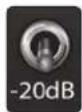
-20 dB Pad. The pad provides 20 dB of attenuation for the microphone preamp only.
Power User Tip: The -20 dB pad reduces the signal level coming into your RC 500, helping to prevent clipping and distortion from high-gain sources. Padding the input increases "headroom" and reduces the likelihood of signal overload.
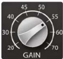
Gain. Your RC500 provides a gain range from +20 dB to +70 dB for the Mic preamp and -20 dB to +15 dB for the Line Input.
2.2 Compressor Controls
2.2 Compressor Controls
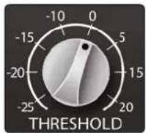
Threshold. Sets the threshold of the compressor. When the signal's amplitude (level) exceeds the threshold setting, the compressor engages. Turning the knob counterclockwise lowers the threshold so that compression begins at a lower amplitude, and more of the input signal is compressed. The threshold can be set from -25 to +20 dBu.
Power User Tip: Your RC 500 compressor has a fixed ratio of 3:1. This ratio will work well for a wide variety of instruments. If you would like more compression, lower the threshold while raising the input level. Lighter compression can be easily achieved by raising the threshold.
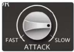
Attack. Attack sets the speed at which the compressor acts on the input signal. A slow attack time (fully clockwise) allows the beginning component of the signal (commonly referred to as the initial transient) to pass through, uncompressed, whereas a fast attack time (fully counter-clockwise) triggers compression immediately when a signal exceeds the threshold. The compressor attack time ranges from 0.5 ms (Fast) to 10 ms (Slow).
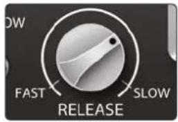
Release. Sets the release of the compressor, which is the time the compressor takes to return the gain reduction back to zero (no gain reduction) after the signal level crosses below the compression threshold. The compressor release time ranges from 40 ms (Fast) to 500 ms (Slow).
Power User Tip: Very short release times can produce a choppy or "jittery" sound, especially when compressing instruments that have a lot of low-frequency components, such as a bass guitar. Very long release times can result in an overcompressed, or "squashed," sound. All ranges of release can be useful, however, and you should experiment to become familiar with different possibilities.
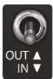
Compressor In/Out. Bypasses the compressor circuit in the signal chain.
2.3 EQ Controls
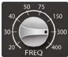
Low Band Frequency. Sets the center frequency of the EQ's low-frequency band. You can adjust the center frequency between 20 and 400 Hz.
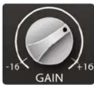
Low Band Gain. Sets the attenuation or boost of the EQ's low-frequency band. The gain can be set between -16 and +16 dB.
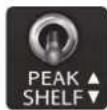
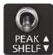
Low Band Shelf. By default, the low band of the EQ is a standard peak filter with a fixed Q of 0.6. When the Shelf switch is engaged, the low band functions as a shelving filter.
Power User Tip: A shelving EQ attenuates or boosts frequencies above or below a specified cutoff frequency. In practice, these types of EQs are much like the treble and bass controls on a car stereo. Like a bass control, a low-shelf filter will raise or lower the gain on all frequencies below the specified cutoff frequency. A high-shelf filter will raise or lower the gain on all frequencies above the specified cutoff frequency, just like a treble control. Shelving EQs can be used to make big changes to the sound very quickly by adding or removing an entire frequency range at once.
In contrast, a peak EQ offers continuous control over the center frequency of the band and over the level (boost/cut) of the designated frequency band, which makes it capable of more subtle changes.
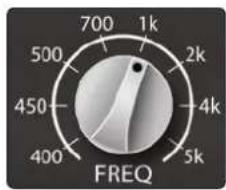
Mid Band Frequency. Sets the center frequency of the EQ's mid-frequency band. You can adjust the center frequency between 400 Hz and 5 kHz.
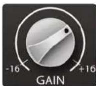
Mid Band Gain. Sets the attenuation of boost of the EQ's mid-frequency band. The gain can be set between -16 and +16 dB.
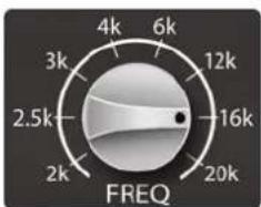
High Band Frequency. Sets the center frequency of the EQ's high-frequency band. You can adjust the center frequency between 2 and 20 kHz.
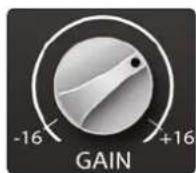
High Band Gain. Sets the attenuation of boost of the EQ's high-frequency band. The gain can be set between -16 and +16 dB.
2.4 VU Meter and Controls
High Band Shelf. By default, the high band of the EQ is a standard peak filter with a fixed Q of 0.6. When the Shelf switch is engaged, the high band functions as a shelving filter.
EQ In/Out. Bypasses the EQ circuit in the signal chain.
2.4 VU Meter and Controls
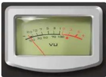
VU Meter. By default, the analog VU meter displays the RC 500's output level.
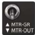
Meter - GR. This switch changes the VU metering to display the compressor's gain reduction rather than the RC 500's output level.
2.5 Master Control
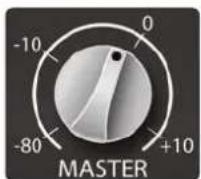
Master Level. Adjusts the overall output volume of the RC 500 between -80 dB and +10 dB.
2.6 Physical Connections
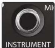
Instrument Input. The 14 " TS connector on the front panel is for use with a passive instrument (guitar, bass, etc.). To use this input, turn the Source Select switch to the Mic/Inst position.
Power User Tip: Passive instruments do not have an internal preamp and should be plugged into an instrument input. Active instruments have an internal preamp and a line-level output and should be plugged into a line input. Plugging a line-level source into the instrument input on the front of the RC 500 risks damage to the circuit and is likely to produce a very loud and distorted audio signal. So don't do that!
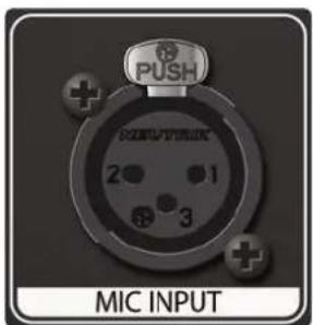
Mic Input. The RC 500 mic preamp works great with all types of microphones, including dynamic, ribbon, and condenser mics. To use this input, turn the Source Select switch to the Mic/Inst position. As previously stated in Section 2.1, if both the Mic and the Instrument inputs are connected, the Mic input will be bypassed, and the Instrument input will be patched through the signal path.
Power User Tip: Dynamic microphones and ribbon microphones (which are a special type of dynamic mic) are generally lower-output devices that, with few exceptions, require no external power source. Sending phantom power to a ribbon mic that doesn't require it can cause severe damage to the mic—usually beyond repair. Condenser microphones are generally more sensitive than dynamic and ribbon microphones and typically require external +48V phantom power. Always review your microphone's documentation and follow its recommended operating practices.
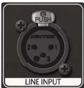
Line Input. This balanced XLR connection can be used for line-level devices such as keyboards, drum machines, and sound modules. To use this input, turn the Source Select switch to the Line position.

Balanced Send. This balanced 14 " TRS output sends the source signal out of your RC 500 before the compressor, EQ, and Master Gain stages. Use this output to insert an external processor into your RC 500's signal path.
Power User Tip: You can use the Balanced Send to record the unprocessed signal, in addition to the compressed/EQ'd signal. This provides you with the flexibility of recording a dynamically processed and EQ'd source, while giving you the option to add dynamics processing to your recorded (unprocessed) signal when mixing. To do this, simply connect the main output of your RC 500 to one input of your audio interface and the Balanced Send to a second output of your interface.
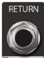
Balanced Return. This balanced 14 " TRS input patches directly to the compressor stage of your RC 500. When using this input to insert an external dynamics processor, you can bypass the compressor, the EQ, or both.
Power User Tip: If you have an external preamp that you would like to use with your RC 500's compressor and EQ, patch it to the Balanced Return, rather than to the Line Input, to completely bypass the first gain stage.
natural_image
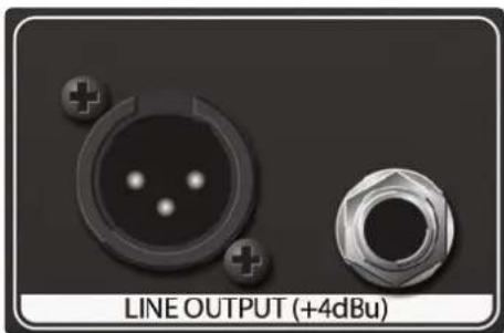
Close-up of two electronic components with no visible text or symbols on the parts themselves.Output. The RC 500 provides both balanced XLR and 1/4" TRS connections. Both output connections are active all the time.
Power User Tip: All input and output connectors are transformer-balanced XLRs with the following wiring standard:
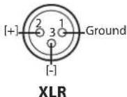
Pin 1: GND Pin 2: High (+) Pin 3: Low (-)
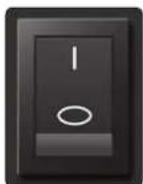
Power Switch. Turn this switch to the [] position to power on your RC 500. The [O] position powers the unit down.

natural_image
Close-up of a black electrical outlet with three pins and two plus signs (no text or symbols visible)IEC Power Connection. Your RC 500 accepts a standard IEC AC power cord.
Note: The input power voltage is set at the factory to correspond with the country to which the RC 500 was shipped.
2.7 Hookup Diagrams
2.7 Hookup Diagrams
2.7.1 Basic Recording Diagram
2.7.2 Advanced Recording Diagram
3 Tutorial
3.1 A Brief Tutorial on Dynamics Processing
The RC 500 includes a custom FET compressor. What follows is an excerpt from a brief tutorial on dynamics processing written by PreSonus president and founder Jim Odom. It is included to help you get the most out of your RC 500. This tutorial will take you through the basics of dynamics processing.
3.1.1 Common Questions Regarding Dynamics Processing
What is dynamic range?
Dynamic range can be defined as the ratio between the loudest possible audio level and the noise floor. For example, if a processor states that the maximum input level before distortion is +24 dBu, and the output noise floor is -92 dBu, then the processor has a total dynamic range of 24 + 92 = 116 dB.
The average dynamic range of an orchestral performance can range from -50 dBu to +10 dBu, on average. This equates to a 60 dB dynamic range. Although 60 dB may not appear to be a large dynamic range, do the math, and you'll discover that +10 dBu is 1,000 times louder than -50 dBu!
Rock music, on the other hand, has a much smaller dynamic range: typically -10 dBu to +10 dBu, or 20 dB. This makes mixing the various signals of a rock performance together a much more tedious task.
Why do we need compression?
Consider the previous discussion: You are mixing a rock performance with an average dynamic range of 20 dB. You wish to add an uncompressed vocal to the mix. The average dynamic range of an uncompressed vocal is around 40 dB. In other words, a vocal performance can go from -30 dBu to +10 dBu. The passages that are +10 dBu and higher will be heard over the mix. However, the passages that are at -30 dBu and below will never be heard over the roar of the rest of the mix. A compressor can be used in this situation to reduce (compress) the dynamic range of the vocal to around 10 dB. The vocal can now be placed at around +5 dBu. At this level, the dynamic range of the vocal is from 0 dBu to +10 dBu. The lower level phrases will now be well above the lower level of the mix, and louder phrases will not overpower the mix, allowing the vocal to "sit in the track." The same points can be made about any instrument in the mix. Each instrument has its place, and a good compressor can assist the engineer in the overall blend.
Does every instrument need compression?
This question may lead many folks to say "absolutely not, overcompression is horrible." That statement can be qualified by defining overcompression. The term itself must have been derived from the fact that you can hear the compressor working. A well-designed and properly adjusted compressor should not be audible! Therefore, the overcompressed sound is likely to be an improper adjustment on a particular instrument—unless, of course, it is done intentionally for effect.
The world's best mixing consoles offer compression on every channel because most instruments need some form of compression, often very subtle, to be properly heard in a mix. Punch, apparent loudness, presence—these are just three of the many terms used to describe the effects of compression. Compression is a form of dynamic-range (gain) control. Audio signals have very wide peak-to-average signal-level ratios (sometimes referred to as dynamic range, which is the difference between the loudest level and the softest level). The peak signal can cause overload in the audio recording or sound-reinforcement chain, resulting in signal distortion.
A compressor is a type of amplifier in which gain is dependent on the signal level passing through it. You can set the maximum level a compressor allows to pass through, thereby causing automatic gain reduction above some predetermined
3.1 A Brief Tutorial on Dynamics Processing
signal level, or threshold. Compression refers, basically, to the ability to reduce, by a fixed ratio, the amount by which a signal's output level can increase relative to the input level. It is useful for lowering the dynamic range of an instrument or vocal, making it easier to record without distorting the recorder. It also assists in the mixing process by reducing the amount of level changes needed for a particular instrument.
Take, for example, a vocalist who moves around in front of the microphone while performing, making the output level vary up and down unnaturally. A compressor can be applied to the signal to help correct this recording problem by reducing the louder passages enough to be compatible with the overall performance.
How severely the compressor reduces the signal is determined by the compression ratio and compression threshold. A ratio of 2:1 or less is considered mild compression, reducing the output by a factor of two for signals that exceed the compression threshold.
As the compression threshold is lowered, more of the input signal is compressed (assuming a nominal input-signal level). Care must be taken not to overcompress a signal, as too much compression destroys the acoustic dynamic response of a performance. (That said, overcompression is used by some engineers as an effect, with killer results!)
Compressors are commonly used for many audio applications. For example:
A kick drum can get lost in a wall of electric guitars. No matter how much the level is increased, the kick drum stays lost in the "mud." A touch of compression can tighten up that kick-drum sound, allowing it to punch through without having to crank the level way up.
A vocal performance usually has a wide dynamic range. Transients (normally the loudest portions of the signal) can be far outside the average level of the vocal signal. Because the level can change continuously and dramatically, it is extremely difficult to ride the level with a console fader. A compressor automatically controls gain without altering the subtleties of the performance.
A solo guitar can seem to be masked by the rhythm guitars. Compression can make your lead soar above the track without shoving the fader through the roof.
Bass guitar can be difficult to record. A consistent level with good attack can be achieved with proper compression. Your bass doesn't have to be washed out in the low end of the mix. Let the compressor give your bass the punch it needs to drive the bottom of the mix.
3.2 Equalizers
Your RC 500 is equipped with a 3-band semi-parametric EQ. Here's a brief explanation of how an EQ functions, as well as some charts to help you navigate the frequency ranges of various instruments so you can quickly choose the best EQ settings for your recordings and live mixes.
3.2.1 What is an EQ?
An equalizer is a filter that allows you to adjust the level of a frequency, or range of frequencies, of an audio signal. In its simplest form, an EQ will let you turn the treble and bass up or down, allowing you to adjust the coloration of, let's say, your car stereo or iPod®. In recording, equalization is a sophisticated art. Good equalization is critical to a good mix.
When used correctly, an equalizer can provide the impression of nearness or distance, "fatten" or "thin" a sound, and help blend or provide separation between similar sounds in a mix allowing them to both shine through the mix.
Parametric EQ
The parametric EQ and semi-parametric EQ are the most common equalizers found in recording and live situations because they offer continuous control over all parameters. A parametric EQ offers continuous control over the audio signal's frequency content, which is divided into several bands of frequencies (most commonly three to seven bands). A fully parametric EQ like those in the StudioLive 32.4.2AI and 24.4.2AI offers control over the bandwidth (basically, the range of frequencies affected), the center frequency of the band, and the level (boost/ cut) of the designated frequency band. It also offers separate control over the Q, which is the ratio of the center frequency to the bandwidth. A semi-parametric EQ provides control over most of these parameters but the Q is fixed. Some devices, such as the StudioLive 16.4.2AI and 16.0.2, have quasi-parametric EQ, which is semi-parametric EQ with a simple, switchable Q setting (typically, High and Low Q).
Q
Q is the ratio of center frequency to bandwidth, and if the center frequency is fixed, then bandwidth is inversely proportional to Q—meaning that as you raise the Q, you narrow the bandwidth. In fully parametric EQs, you have continuous bandwidth control and/or continuous Q control, which allows you to attenuate or boost a very narrow or wide range of frequencies.
A narrow bandwidth (higher Q) has obvious benefits for removing unpleasant tones. Let's say the snare drum in your mix has an annoying ring to it. With a very narrow bandwidth, you can isolate this one frequency (usually around 1 kHz) and remove, or reject, it. This type of narrow band-reject filter is also known as a notch filter. By notching out the offending frequency, you can remove the problem without removing the instrument from the mix. A narrow bandwidth is also useful in boosting pleasant tones of an instrument such as the attack. Take for instance, a kick drum. A kick drum resonates somewhere between 60 to 125 Hz but the attack of the kick drum is much higher at 2 to 5 kHz. By setting a narrow bandwidth and boosting the attack a bit, you can achieve a punchier kick drum without overpowering the rest of the mix.
A broad bandwidth accentuates or attenuates a larger band of frequencies. The broad and narrow bandwidths (high and low Q) are usually used in conjunction with one another to achieve the desired effect. Let's look at our kick drum again. We have a kick drum that has a great, big, low-end sound centered around 100 Hz and an attack hitting almost dead-on at 4 kHz. In this example, you would use a broad bandwidth in the low frequency band, centered at 100 Hz, and a narrow bandwidth boosted at 4 kHz. In this way you are accentuating the best and downplaying everything else this particular kick drum has to offer.
3.2 Equalizers
Shelving EQ
A shelving EQ attenuates or boost frequencies above or below a specified cutoff point. Shelving equalizers come in two different varieties: high-pass and low-pass. Low-pass shelving filters pass all frequencies below the specified cutoff frequency while attenuating all the frequencies above it. A high-pass filter does the opposite: passing all frequencies above the specified cut-off frequency while attenuating everything below.
3.2.2 Equalization Settings: How to Find the Best and Leave the Rest
How do you find the best and worst each instrument has to offer and adjust their frequency content accordingly? Here's a quick guide:
- First, solo just the instrument with which you are working. Most engineers start building their mix with the drums and work from the bottom up (kick, snare, toms, hi-hat, overheads). Each instrument resonates primarily in a specific frequency band, so if you are working on your kick-drum mic, start with the lowest band of the EQ. Tune in the best-sounding low end and move on to the attack. It is not uncommon to hear an annoying ringing or a "twang" mixed in with your amazing-sounding low end and perfect attack, so your next task will be to find that offending frequency and notch it out. Once you are satisfied with your kick drum, mute it, and move on to the next instrument.
•Taking your time with equalization is well worth the effort. Your mix will have better separation and more clarity.
Additional advice:
- You can only do so much. Not every instrument can or should have a full, rich low end and a sharp attack. If every instrument is EQ'd to have the same effect, it will lose its identity in the mix. Your goal is not individual perfection, it is perfection in unity.
- Step away from the mix. Your ears get fatigued, just like the rest of you. If you are working particularly hard on one instrument, your ears will be quite literally numbed to that frequency range.
- Your memory is not what you think it is. Comparing a flat EQ and the curve that you've created allows you to see and hear exactly what you've done. So be honest with yourself. Sometimes that EQ setting you've been working on for 15 minutes is not the right choice, so move on.
- Never be afraid of taking a risk. The best EQ tricks were found by mad scientists of sound.
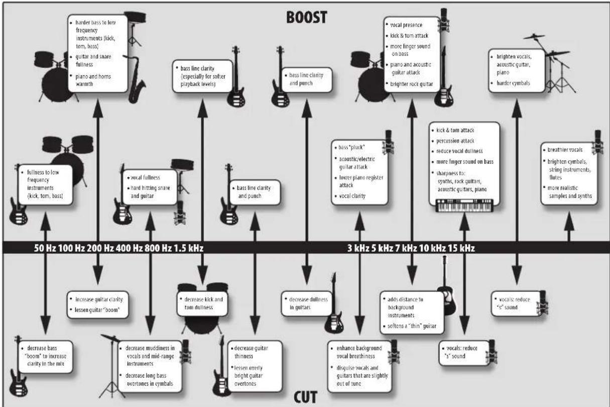
3.2.3 EQ Frequency Charts
With every instrument, there are frequencies that can be attenuated or boosted to add clarity or fullness. Altering the wrong frequencies can make an instrument shrill, muddy, or just downright annoying. The following two charts suggest frequency ranges that should be accentuated or downplayed for the most common instruments. These are just suggestions; the frequencies may need to be adjusted up or down depending on the instrument, room, and microphone.
Table 1
| Instrument What to Cut Why to Cut What to Boost Why to Boost | ||||
| Human Voice | 7 kHz Sibilance 8 kHz Big sound | |||
| 2 kHz Shrrill 3 kHz and above | Clarity | |||
| 1 kHz | Nasal | 200-400 Hz | Body | |
| 80 Hz and below | Popping P's | |||
| Piano | 1-2 kHz | Tinny | 5 kHz | More presence |
| 300 Hz | Boomy | 100 Hz | Bottom end | |
| Electric Guitar | 1-2 kHz | Shrill | 3 kHz | Clarity |
| 80 Hz and below | Muddy | 125 Hz | Bottom end | |
| Acoustic Guitar | 2-3 kHz | Tinny | 5 kHz and above | Sparkle |
| 200 Hz | Boomy | 125 Hz | Full | |
| Electric Bass | 1 kHz | Thin | 600 Hz | Growl |
| 125 Hz | Boomy | 80 Hz and below | Bottom end | |
| String Bass | 600 Hz | Hollow | 2-5 kHz | Sharp attack |
| 200 Hz | Boomy | 125 Hz and below | Bottom end | |
| Snare Drum | 1 kHz | Annoying | 2 kHz | Crisp |
| 150-200 Hz | Full | |||
| 80 Hz Deep | ||||
| Kick Drum | 400 Hz | Muddy | 2-5 kHz | Sharp attack |
| 80 Hz and below | Boomy | 60-125 Hz | Bottom end | |
| Toms | 300 Hz | Boomy 2-5 kHz | Sharp attack | |
| 80-200 Hz | Bottom end | |||
| Cymbals | 1 kHz | Annoying | 7-8 kHz | Sizzle |
| 8-12 kHz | Brilliance | |||
| 15 kHz | Air | |||
| Horns | 1 kHz | Honky | 8-12 kHz | Big sound |
| 120 Hz and below | Muddy | 2 kHz | Clarity | |
| String section | 3 kHz Shrrill 2 kHz | Clarity | ||
| 120 Hz and below | Muddy | 400-600 Hz | Lush and full | |
3.2 Equalizers
Table 2
flowchart
graph TD
    A["BOOST"] --> B["50 Hz 100 Hz 200 Hz 400 Hz 800 Hz 1.5 kHz"]
    A --> C["3 kHz 5 kHz 7 kHz 10 kHz 15 kHz"]
    D["CUT"] --> E["• decrease bass "boom" to increase clarity in the mix"]
    D --> F["• decrease mudiness in vocals and mid-range Instruments"]
    D --> G["• decrease long bass overtones in cymbals"]
    D --> H["• decrease guitar thinness"]
    D --> I["• lessen overly bright guitar overtones"]
    A --> J["• burdened vocals, acoustic guitar, piano"]
    A --> K["• sharper vocals"]
    A --> L["• greater voices, string instruments, flutes"]
    A --> M["• more realistic samples and synths"]

    N["BOOST"] --> O["• burdened bass to low frequency instruments (kick, tom, bass), guitar and snare fullness, piano and horns warmth"]
    N --> P["• bass line clarity (especially for softer playback levels)"]
    N --> Q["• bass line clarity and punch"]
    A --> R["• burdened vocals, acoustic guitar, piano"]
    A --> S["• sharper vocals"]

    T["CUT"] --> U["• decrease bass "boom" to increase clarity in the mix"]
    T --> V["• decrease mudiness in vocals and mid-range Instruments"]
    T --> W["• decrease long bass overtones in cymbals"]
    T --> X["• decrease guitar thinness"]
    T --> Y["• lessen overly bright guitar overtones"]
    T --> Z["• decrease dullness in guitars"]
    T --> AA["• enhance background vocal breathiness"]
    T --> AB["• disguise vocals and guitars that are slightly out of tune"]

    AC["BOOST"] --> AD["• burdened vocals, acoustic guitar, piano"]
    AC --> AE["• sharper vocals"]
    AC --> AF["• greater voices, string instruments, flutes"]
    AC --> AG["• more realistic samples and synths"]
    AC --> AH["• greater vocals, acoustic guitar, piano"]

    AI["BOOST"] --> AJ["• burdened vocals, acoustic guitar, piano"]
    AI --> AK["• sharper vocals"]
    AI --> AL["• greater vocals, acoustic guitar, piano"]
    AI --> AM["• more realistic samples and synths"]
    AI --> AN["• greater vocals, acoustic guitar, piano"]

    AO["CUT"] --> AP["• burdened vocals, acoustic guitar, piano"]
    AO --> AQ["• sharper vocals"]
    AO --> AR["• greater vocals, acoustic guitar, piano"]
    AO --> AS["• more realistic samples and synths"]
    AO --> AT["• greater vocals, acoustic guitar, piano"]

    AU["BOOST"] --> AV["• burdened vocals, acoustic guitar, piano"]
    AU --> AW["• sharper vocals"]
    AU --> AX["• greater vocals, acoustic guitar, piano"]
    AU --> AY["• more realistic samples and synths"]
    AU --> AZ["• greater vocals, acoustic guitar, piano"]

    BA["BOOST"] --> BB["• burdened vocals, acoustic guitar, piano"]
    BA --> BC["• sharper vocals"]
    BA --> BD["• more vocals, acoustic guitar, piano"]
    BA --> BE["• more realistic samples and synths"]
    BA --> BF["• greater vocals, acoustic guitar, piano"]

    BG["CUT"] --> BH["• burdened vocals, acoustic guitar, piano"]
    BG --> BI["• sharper vocals"]
    BG --> BJ["• more vocals, acoustic guitar, piano"]
    BG --> BK["• more realistic samples and synths"]
    BG --> BL["• greater vocals, acoustic guitar, piano"]

    BM["BOOST"] --> BN["50 Hz 100 Hz 200 Hz 400 Hz 800 Hz 1.5 kHz"]
    BM --> BO["3 kHz 5 kHz 7 kHz 10 kHz 15 kHz"]
4 Resources
4.1 Audio Specifications
Input Impedance
| Microphone 1500 Ω |
| Line 1 kΩ |
| Instrument 1 MΩ |
Maximum Input Level
| Microphone (-20 dB Pad Out) 0 dBu |
| Microphone (-20 dB Pad In) -20 dBu |
| Line +18 dBu |
| Instrument 0 dBu |
Gain Range
| Microphone (-20 dB Pad Out) +20 to +70 dB |
| Line -20 to +15 dB |
| Instrument +5 to +50 dB |
Performance
| Noise Floor (All inputs, minimum gain) -102 dBu (AWtd) | |
| Microphone EIN (20 Hz-20 kHz) -125 dBu (AWtd) | |
| Frequency Response | 10 Hz to 25 kHz +/-1 dB |
| Maximum Output Level | +24 dBu |
| Output Impedance | 50 Ω |
EQ
| Type | 2nd Order Shelving |
| Q | 0.5 |
| Low Band | 20 Hz to 400 Hz |
| Mid Band | 400 Hz to 5 kHz |
| High Band | 2 kHz to 20 kHz |
Compressor
| Type | FET VCA with RMS based control |
| Attack Time (Variable) | Fast (0.5 ms) to Slow (10 ms) |
| Release Time (Variable) | Fast (30 ms) to Slow (500 ms) |
| Threshold (Variable) | -25 dB to +20 dBu |
| Ratio (Fixed) | 3:1 |
Physical
| Weight | 7 lb. 3 oz. (3.26 kg) |
| Dimensions (W x H x D) | 19" (482.6 mm) x 1.72" (43.6 mm) x 7.69" (195.3 mm) |
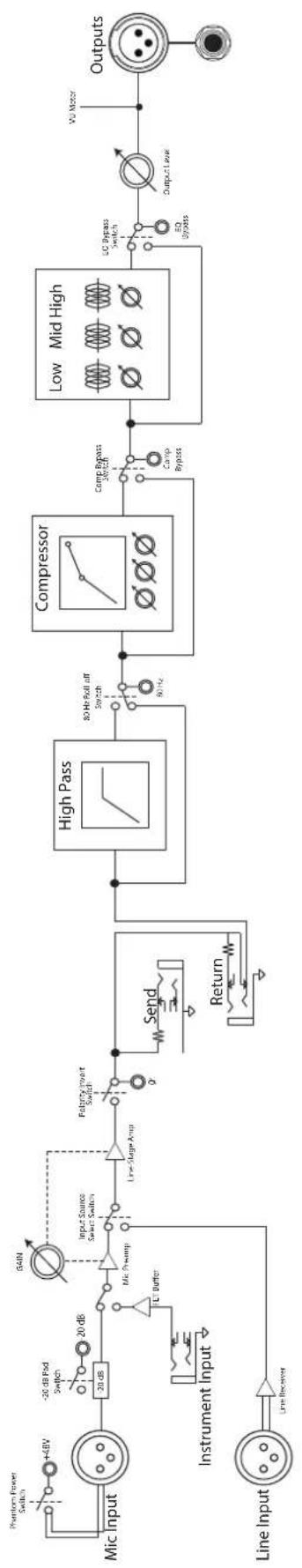
4.2 RC 500 Block Diagram
4.2 RC 500 Block Diagram
flowchart
graph LR
    A["Line Input"] --> B["Instrument Input"]
    B --> C["Line Receiver"]
    C --> D["Line Regener"]
    D --> E["Input Source Select Switch"]
    E --> F["Line Stage Amp"]
    F --> G["Polypass Invert Switch"]
    G --> H["High Pass"]
    H --> I["80 Hz Roll off Switch"]
    I --> J["Compressor"]
    J --> K["Comp Bypass Switch"]
    K --> L["Low Mid High"]
    L --> M["Output Level"]
    M --> N["WU Motor"]
    O["Phantom Power Switch"] --> P["+4BV"]
    Q["-20 dB Pad Switch"] --> R["20 dB"]
    S["54IN"] --> T["Mic Pump"]
    U["1000Ω"] --> V["Line Buffer"]
    W["60Hz"] --> X["Return"]
    Y["60Hz"] --> Z["Send"]
    AA["60Hz"] --> AB["Line Regener"]
    AC["60Hz"] --> AD["Line Regener"]
4.3 RC 500 Recall Sheet
NOTES:
SONG TITLE:
DATE:
ARTIST: MIC/INST:
DATE: ____ SONG TITLE: ____ NOTES:
ARTIST: MIC/INST:
4.4 Troubleshooting
No power.
First make sure your unit is plugged in. If it's connected to a power conditioner, verify that the power conditioner is turned on and functioning properly. Check the fuse on the back panel of the RC 500. (Be sure to disconnect the power from the RC 500 before opening the fuse housing.) A blown fuse may look black on the inside, or the wire inside might appear broken, and a very black fuse indicates that something may have shorted out. Try replacing the fuse with a new one. Please refer to the information on the rear panel of your RC 500 to select the correct fuse. If the fuse blows again, please contact PreSonus to get your RC 500 repaired.
Not passing audio.
If the RC 500 appears to power on but it's not passing signal (the lights are on but nobody's home), first check all the cables connected to your RC 500 and make sure that they are working correctly. Also, verify that the Source Select switch is set to the correct input and that the Gain and Output Level controls are set to provide enough amplitude for the signal. If you have your RC 500 connected to a patch bay, try connecting a source directly to the RC 500 to rule out a problem with the patch bay.
4.5 Warranty
PreSonus Audio Electronics, Inc., warrants this product to be free of defects in material and workmanship for a period of one year from the date of original retail purchase. This warranty is enforceable only by the original retail purchaser. To be protected by this warranty, the purchaser must complete and return the enclosed warranty card within 14 days of purchase. During the warranty period PreSonus shall, at its sole and absolute option, repair or replace, free of charge, any product that proves to be defective on inspection by PreSonus or its authorized service representative. To obtain warranty service, the purchaser must first call or write PreSonus at the address and telephone number printed below to obtain a Return Authorization Number and instructions for where to return the unit for service. All inquiries must be accompanied by a description of the problem. All authorized returns must be sent to the PreSonus repair facility postage prepaid, insured, and properly packaged. PreSonus reserves the right to update any unit returned for repair. PreSonus reserves the right to change or improve the design of the product at any time without prior notice. This warranty does not cover claims for damage due to abuse, neglect, alteration, or attempted repair by unauthorized personnel and is limited to failures arising during normal use that are due to defects in material or workmanship in the product. Any implied warranties, including implied warranties of merchantability and fitness for a particular purpose, are limited in duration to the length of this limited warranty. Some states do not allow limitations on how long an implied warranty lasts, so the above limitation may not apply to you. In no event will PreSonus be liable for incidental, consequential, or other damages resulting from the breach of any express or implied warranty, including, among other things, damage to property, damage based on inconvenience or on loss of use of the product, and, to the extent permitted by law, damages for personal injury. Some states do not allow the exclusion of limitation of incidental or consequential damages, so the above limitation or exclusion may not apply to you. This warranty gives you specific legal rights, and you may also have other rights, which vary from state to state. This warranty only applies to products sold and used in the United States of America. For warranty information in all other countries, please refer to your local distributor.
PreSonus Audio Electronics, Inc.
7257 Florida Blvd.
Baton Rouge, LA 70806 USA
www.presonus.com
Added bonus: PreSonus' previously Top Secret recipe for...
Chicken and Andouille Gumbo
Ingredients:
•1 C All-Purpose flour
• ^3/_4 C Vegetable Oil
•1 large onion (diced)
•1 small onion (quartered)
- 6 celery stalks (diced)
•1 large green bell pepper (diced)
•3 cloves garlic (2 minced, 1 whole)
•1 lb link Andouille sausage
•4 Chicken leg quarters
•4 qt water
•4 bay leaves
•1 tsp thyme
•1 tsp Old Bay seasoning
•1-2 C frozen okra, sliced
- 14 C fresh parsley, minced
- 6-8 eggs (optional)
Cooking Instructions:
- In a large pot, combine whole chicken leg quarters, water, quartered onion, Old Bay, 2 bay leaves and 1 whole clove garlic. Cover and bring to a low boil. Simmer stock until chicken is falling off the bone. Remove the chicken and set aside. Discard the onion, bay leaves, and garlic, reserving the liquid.
- In a heavy saucepan, heat 1 Tbsp of the oil on medium high heat and brown the andouille until it is cooked through. Set aside sausage for later.
- In the same saucepan, add and heat remaining oil. Slowly add flour 1-2 Tbsp at a time, stirring continuously. Continue cooking and stirring the roux until it is a dark brown (it should look like melted dark chocolate). Be careful to not to get the oil too hot or the flour will burn and you'll have to start over.
- Once roux has reached the correct color, add diced onion, celery, green pepper, and minced garlic. Cook until vegetables are very tender. Do not cover.
- Slowly add 1 quart of chicken broth and bring to a low boil, stirring constantly.
- Transfer roux mixture to a soup pot and bring to low boil. Do not cover, the roux will settle on the bottom of the pot and burn.
- Add remaining chicken broth, bay leaves, and thyme. Simmer for 30 minutes.
- While gumbo is simmering, debone and shred chicken and slice the andouille.
- Add chicken and andouille to gumbo and return to a simmer. Simmer for 30-45 minutes.
- Stir in frozen okra and parsley and bring to a rolling boil.
- Optional: Crack one egg into a teacup and quickly pour into the boiling gumbo. Repeat with the other eggs being careful not to cluster them too closely. After all the eggs have risen back to the surface, reduce heat and simmer.
-
- Correct seasoning with salt and pepper (red, white and/or black) if necessary.
- Serve over rice with potato salad.
Serves 12
© 2013 PreSonus Audio Electronics, Inc. All Rights Reserved. AudioBox, CoActual, DigiMax, Eris, FireStudio, Nimbit, PreSonus, QMix, Riff to Release, Sceptre, StudioLive, and XMAX are trademarks or registered trademarks of PreSonus Audio Electronics, Inc. Capture, Impact, Mixverb Presence, RedLightDist, SampleOne, Studio One, and Tricomp are trademarks or registered trademarks of PreSonus Software Ltd. Mac and Mac OS are registered trademarks of Apple, Inc., in the U.S. and other countries. Windows is a registered trademark of Microsoft, Inc., in the U.S. and other countries. Temporal EQ and TQ are trademarks of Fulcrum Acoustic. Other product names mentioned herein may be trademarks of their respective companies. All specifications subject to change without notice....except the recipe, which is a classic.
RC 500
Channel Strip with Solid-State Preamp, Compressor, and EQ
Owner's Manual