
RDM-2INC - Dimmer AMX - Free user manual and instructions
Find the device manual for free RDM-2INC AMX in PDF.


| Product Type | Dimmer |
| Brand | AMX |
| Model | RDM-2INC |
| Category | Dimmer (Gradateur) |
| Channels | 2 |
| Load Type | Incandescent |
| Voltage | 120V AC, 60 Hz |
| Maximum Load per Channel | 600W |
| Total Maximum Load | 1200W |
| Control Protocol | RDM (Remote Device Management) |
| Mounting | DIN rail or wall box |
| Dimensions | 4.5 x 2.5 x 1.5 inches (114 x 64 x 38 mm) |
| Weight | 0.5 lbs (225 g) |
| Power Supply | Line voltage (120V) |
| Cooling | Passive (no fan) |
| Operating Temperature | 32°F to 104°F (0°C to 40°C) |
| Safety Certifications | UL, CE |
| Warranty | 2 years |
| Main Functions | Dimming, On/Off, RDM monitoring |
| Maintenance | Clean with dry cloth; do not use solvents |
| Safety | Disconnect power before installation; use proper wiring |
| Spare Parts & Repairability | Not user-serviceable; contact AMX for replacement |
| General Information | Dual-channel dimmer for incandescent loads with RDM control |
Frequently Asked Questions - RDM-2INC AMX
User questions about RDM-2INC AMX
0 question about this device. Answer the ones you know or ask your own.
Ask a new question about this device
Download the instructions for your Dimmer in PDF format for free! Find your manual RDM-2INC - AMX and take your electronic device back in hand. On this page are published all the documents necessary for the use of your device. RDM-2INC by AMX.
USER MANUAL RDM-2INC AMX
Operation/Reference Guide
RADIA
Lighting Control System
Controllers / Modules / Cards

AMX Limited Warranty and Disclaimer
This Limited Warranty and Disclaimer extends only to products purchased directly from AMX or an AMX Authorized Partner which include AMX Dealers, Distributors, VIP's or other AMX authorized entity.
AMX warrants its products to be free of defects in material and workmanship under normal use for three (3) years from the date of purchase, with the following exceptions:
- Electroluminescent and LCD Control Panels are warranted for three (3) years, except for the display and touch overlay components are warranted for a period of one (1) year.
• Disk drive mechanisms, pan/tilt heads, power supplies, and MX Series products are warranted for a period of one (1) year. - AMX lighting products are guaranteed to switch on and off any load that is properly connected to our lighting products, as long as the AMX lighting products are under warranty. AMX also guarantees the control of dimmable loads that are properly connected to our lighting products. The dimming performance or quality there of is not guaranteed, impart due to the random combinations of dimmers, lamps and ballasts or transformers.
- AMX software is warranted for a period of ninety (90) days.
- Batteries and incandescent lamps are not covered under the warranty.
- AMX AutoPatch Epica, Modula, Modula Series4, Modula CatPro Series and 8Y-3000 product models will be free of defects in materials and manufacture at the time of sale and will remain in good working order for a period of three (3) years following the date of the original sales invoice from AMX. The three-year warranty period will be extended to the life of the product (Limited Lifetime Warranty) if the warranty card is filled out by the dealer and/or end user and returned to AMX so that AMX receives it within thirty (30) days of the installation of equipment but no later than six (6) months from original AMX sales invoice date. The life of the product extends until five (5) years after AMX ceases manufacturing the product model. The Limited Lifetime Warranty applies to products in their original installation only. If a product is moved to a different installation, the Limited Lifetime Warranty will no longer apply, and the product warranty will instead be the three (3) year Limited Warranty.
All products returned to AMX require a Return Material Authorization (RMA) number. The RMA number is obtained from the AMX RMA Department. The RMA number must be clearly marked on the outside of each box. The RMA is valid for a 30-day period. After the 30-day period the RMA will be cancelled. Any shipments received not consistent with the RMA, or after the RMA is cancelled, will be refused. AMX is not responsible for products returned without a valid RMA number.
AMX is not liable for any damages caused by its products or for the failure of its products to perform. This includes any lost profits, lost savings, incidental damages, or consequential damages. AMX is not liable for any claim made by a third party or by an AMX Authorized Partner for a third party.
This Limited Warranty does not apply to (a) any AMX product that has been modified, altered or repaired by an unauthorized agent or improperly transported, stored, installed, used, or maintained; (b) damage caused by acts of nature, including flood, erosion, or earthquake; (c) damage caused by a sustained low or high voltage situation or by a low or high voltage disturbance, including brownouts, sags, spikes, or power outages; or (d) damage caused by war, vandalism, theft, depletion, or obsolescence.
This limitation of liability applies whether damages are sought, or a claim is made, under this warranty or as a tort claim (including negligence and strict product liability), a contract claim, or any other claim. This limitation of liability cannot be waived or amended by any person. This limitation of liability will be effective even if AMX or an authorized representative of AMX has been advised of the possibility of any such damages. This limitation of liability, however, will not apply to claims for personal injury.
Some states do not allow a limitation of how long an implied warranty last. Some states do not allow the limitation or exclusion of incidental or consequential damages for consumer products. In such states, the limitation or exclusion of the Limited Warranty may not apply. This Limited Warranty gives the owner specific legal rights. The owner may also have other rights that vary from state to state. The owner is advised to consult applicable state laws for full determination of rights.
EXCEPT AS EXPRESSLY SET FORTH IN THIS WARRANTY, AMX MAKES NO OTHER WARRANTIES, EXPRESSED OR IMPLIED, INCLUDING ANY IMPLIED WARRANTIES OF MERCHANTABILITY OR FITNESS FOR A PARTICULAR PURPOSE. AMX EXPRESSLY DISCLAIMS ALL WARRANTIES NOT STATED IN THIS LIMITED WARRANTY. ANY IMPLIED WARRANTIES THAT MAY BE IMPOSED BY LAW ARE LIMITED TO THE TERMS OF THIS LIMITED WARRANTY. EXCEPT AS OTHERWISE LIMITED BY APPLICABLE LAW, AMX RESERVES THE RIGHT TO MODIFY OR DISCONTINUE DESIGNS, SPECIFICATIONS, WARRANTIES, PRICES, AND POLICIES WITHOUT NOTICE.
Table of Contents
Introduction ...... 1
Features.... 1
Applications.... 2
Controllers....2
AMX Lighting Control Equipment.... 3
Installation 5
Space Requirements 5
Conduit 5
Enclosure Dimensions 6
RDA-ENC2, -ENC4, and -ENC6 Enclosure and Dimensions 6
RDA-ENC6B and RDA-ENC12B Enclosures and Dimensions 6
Mounting AMX Lighting Enclosures.... 7
High-Voltage Connections 7
Connecting High-Voltage, Single-Phase Input Power and Loads 8
RDA-ENC6B 120 VAC Single Phase Line Input.... 8
RDA-ENC6B 120/240 VAC Line Input (Single Phase) 9
Connecting High-Voltage, Three-Phase Input Power and Loads 9
RDA-ENC6B 120/208 VAC Line Input (Three Phase) 10
RDA-ENC6B Three Phase Line Input Connector Reference.... 10
RDA-ENC6 and RDA-ENC12 Power Distribution and Line Input References.... 11
Installing RDM Modules Into an Enclosure 12
Low-Voltage Connections 13
Module Connections 14
Green Status LED Indicator 14
Red Status LED Indicators 14
Configuring and Connecting PROlink.... 14
Configuring and Connecting AxLink.... 16
Connecting dry closures.... 16
Default Mode (Reset).... 17
External Power 18
Compatible Ballast Information ....19
AC-Controlled Magnetic Ballasts 19
AC-Controlled Electronic Ballasts (3-Wire Ballasts) 19
DC-Controlled Electronic Ballasts (4-Wire Ballasts).... 20
Ballast Interfaces and 2-Wire Ballasts 20
Glossary 21
Table of Contents
Introduction
The AMX Radia Lighting Control System™ employs a dual-platform programming architecture that supports both the Axcess programming language and PROlink. The AMX Lighting product line is modular by design, and includes a wide variety of integrated dimmer control modules, dimmer modules, and also switch/relay modules. There are also circuit cards that can control dimming and switching of incandescent, fluorescent, neon (cold-cathode), high and low-voltage equipment, loads (motors), electronic and magnetic ballasts.
These cards and controllers can be housed in any of our five enclosures to ensure complete compliance with any spacing/application requirements. Once the lighting control requirements are defined, you can choose from the extensive group of lighting controllers, modules, etc., install them into the best-suited enclosures, and create the perfect lighting control system for your customers.
FIG. 1 shows some of the AMX Lighting Control System components.

FIG. 1 AMX Lighting Control System components
Features
The AMX Lighting Control System features include:
- Controls up to 1,500 dimmers or 255 6-channel devices (approximate) with a AMX Axcess Control System complete with dimmer-level feedback
● Controls up to 60 dimmers with standalone PROlink systems
● Supports 128 lighting scene presets stored in 16K of non-volatile memory
● Recalls up to 8 of 128 presets with contact closures - Modular and scalable lighting system configurations of one to 1,500 dimmers
● Supports both Axcess and PROlink programming languages - Modules are UL and C-UL listed for United States and Canadian compliance
Applications
You can use the AMX Lighting Control System for commercial, corporate, and residential applications. The dual-platform Axcess and PROlink control architecture can address virtually any number of lighting zones. Entire residential or commercial lighting systems can be manually controlled or fully automated. AMX Lighting systems can also be integrated into existing Axcess presentation/control systems.
Residential applications can be divided into inter-linked lighting zones using central and local control configurations. FIG. 2 shows a sample AMX Lighting system configuration using PROlink, dry closure, and AxLink devices.
![graph TD A["Touch panel"] -->|AxLink| B["AMX Lighting Controllers"] B --> C["Wall panel"] C --> D["PROlink"] D --> E["AMX Lighting Controllers"] E --> F["Wall panel"] F --> G["PROlinkPROlink"] G --> H["AMX Lighting Controllers"] H --> I["Wall panel"] I --> J["PROlinkPROlink"] J --> K["AMX Lighting C…](/content/2026/05/1068386/images/54e7a0d5a20ab75eeb9645b774134e72a99bb83e3588079e91ddca16144b53c7.jpg)
FIG. 2 Sample AMX Lighting Control System
Controllers
The four controllers available for AMX Lighting installations include the RDD-DM4 (4-channels), RDD-DM6 (6-channels) Integrated Dimmer Control Modules, and the RDC-DC (6-channel) and RDC-PDC Pro (6-channel) Dimmer Control Cards.
AMX Lighting Control Equipment
The following table lists all of the AMX Lighting Control System equipment. Refer to the installation sheets for these enclosures, control modules, and dimmer modules for detailed wiring drawings, application notes, and specifications.
AMX Lighting Control Equipment
| AMX Lighting enclosures | |
| RDA-ENC2 2-module enclosure for single-phase dimmer modules | |
| RDA-ENC4 4-module enclosure for dimmer modules | |
| RDA-ENC6 6-module enclosure for single-phase dimmer modules | |
| RDA-ENC6B 6-module, 6-breaker (20 A each) enclosure for multi-phase wiring for one RDA-PDC module (two or three phase configuration) | |
| RDA-ENC12B 6-module, 12-breaker (20 A each) enclosure that supports multi-phase wiring for two RDA-PDC modules | |
| Control cards | |
| RDC-DC 6-channel, single-phase control card (120, 240, or 277 VAC) | |
| RDC-PDC 6-channel, dimmer control card (120 or 240 VAC) | |
| Integrated dimmer control modules | |
| RDD-DM4 4-channel integrated dimmer control module (120 or 240 VAC) | |
| RDD-DM6 6-channel integrated dimmer control module (120 or 240 VAC) | |
| Dimmer modules | |
| RDA-CKM Dual Choke module (350 μS) | |
| RDA-PSM Power supply module | |
| RDM-2DC Dual VDR module (2400 W x 2, 0-12 VDC) | |
| RDM-2FDB Dual FDB module (2400 W x 2) | |
| RDM-2HSW Dual heavy-duty switch module (2400 W x 2) | |
| RDM-2INC Dual incandescent dimming module (2400 W x 2) | |
| RDM-2MR Dual mercury relay module (10 A x 2) | |
| RDM-2PR Dual peak relay module (2400 W x 2) | |
| RDM-2SWM Dual switch module (2400 W) | |
| RDM-22ZC Dual zero cross module (2400 W) | |
| RDM-3DC Triple VDR module, 2400 W x3, 0-12 VDC | |
| RDM-3FDB Triple FDB module (2400 W x 3) | |
| RDM-3HSW Triple heavy-duty switch module (2400 W x 3) | |
| RDM-3MR Triple mercury relay module (10 A x 3) | |
| RDM-3SWM Triple switch module (20 A x 3) | |
| RDM-DC DC dimmer module, 1920 W, 0-12 VDC | |
| RDM-2DC Dual DC dimmer module, 1920 W, 0-12 VDC (x2) | |
| RDM-3DC Triple DC dimmer module, 1920 W, 0-12 VDC (x3) | |
| RDM-DPSM Double-pole, single-throw module (2400 W) | |
| RDM-HDC Heavy duty DC module, 2400 W, 0-12 VDC | |
| RDM-HFDB Heavy duty FDB module (20 A) | |
| RDM-HSW Heavy-duty switch module (2400 W) | |
| RDM-INC Incandescent dimming module (2400 W) | |
| RDM-INC50 Incandescent dimming module (6000 W) | |
| RDM-MDM Multimode dimming module (2400 W/20 A) | |
| RDM-MR Mercury relay module (10 A) | |
| AMX Lighting Control Equipment (Cont.) | |
| Dimmer modules (Cont.) | |
| RDM-MR35 Mercury relay module (35 A) | |
| RDM-MR60 Mercury relay module (60 A) | |
| RDM-PR Peak relay module (2400 W) | |
| RDM-SWM Switch module (2400 W) | |
| RDM-ZC Zero-cross module (2400 W) | |
| RDM-ZC50 Zero-cross module (6000 W) |
Installation
Space Requirements
AMX Lighting control installations require very little space. Enclosures are the main concern. All enclosures are mounted flush, on a vertical surface and must have a minimum clearance of 12" (304.8 mm) above and below to allow for air circulation. Physical dimensions for each enclosure are described in the Installation section.
Conduit
Conduit runs depend on the enclosures you use and their AMX Lighting modules. All enclosures have conduit knockouts on the top for high-voltage connections, and knockouts on the bottom for low-voltage connections. All conduit knockouts allow for 1/2, 3/4, and 1-inch (12.7 mm, 19.0 mm, and 25.4 mm) conduits as shown in FIG. 3. You should also consider these recommendations prior to installing enclosures:
- Install separate conduit for lighting loads. The recommended knockout for loads is located on the top center of the enclosure.
- Install separate conduit for the 120 VAC wiring to the line input terminal block. The recommended knockouts for incoming power feeds are located on the top-left and top-right sides of the AMX Lighting enclosure.
Install separate conduit for low-voltage signals for dry closures, AxLink, and PROlink connections. The recommended knockout for these control connections is located on the bottom of the enclosure. There are additional knockouts on the bottom-left and bottom-right sides of the enclosures for alternate low-voltage connections.
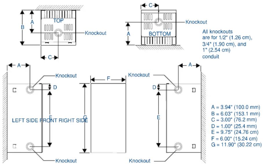
FIG. 3 Knockout locations (RDA-ENC2 used as example)

Install the control modules according to local and National Electrical Code (NEC) regulations.
Enclosure Dimensions
RDA-ENC2, -ENC4, and -ENC6 Enclosure and Dimensions
FIG. 4 shows the dimensions for the RDA-ENC2, RDA-ENC4, and RDA-ENC6 enclosures.

FIG. 4 RDA-ENC2, RDA-ENC4, and RDA-ENC6 enclosure dimensions
RDA-ENC6B and RDA-ENC12B Enclosures and Dimensions
FIG. 5 shows the dimensions for the RDA-ENC6B and RDA-ENC12B enclosures.

FIG. 5 RDA-ENC6B and ENC12B enclosures and dimensions
Mounting AMX Lighting Enclosures
AMX Lighting enclosures must be mounted on a vertical surface with a minimum of 12" (304.8 mm) clearance above and below the enclosure. FIG. 6 shows the centerline reference points and dimensions.
- Remove the front cover by removing the screws at the bottom of the enclosure; two tabs suspend the cover from the top.
- Position the enclosure on the wall so that it is level, with the high-voltage terminals of the unit at the top.
- Mark the four mounting holes according to the dimensions shown in Figure 8.
- Install screws at the marks. The maximum screw size is #12.
- Hang the enclosure on the four screws. Then, tighten the screws.

FIG. 6 Center-line reference points and dimensions
Refer to the Dimmer Enclosures with Breakers installation guide for more information.
High-Voltage Connections
FIG. 7 shows an example of a high-voltage connection for an RDD-DM4 controller.

NOTE
All high-voltage connections must comply with Class 1 wiring codes.
Each AMX Lighting module has its high-voltage connectors marked on its circuit board. LINE, LOAD, and NEUTRALs are also clearly marked.
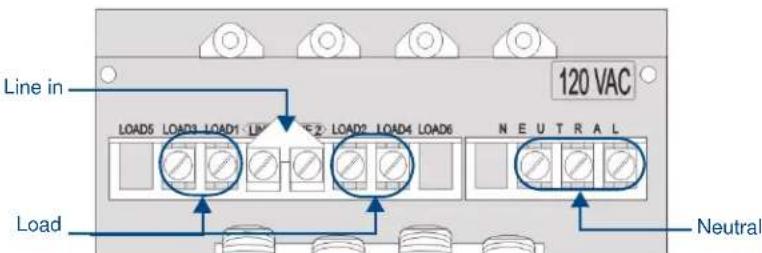
FIG. 7 High-voltage connections for an RDD-DM4
Connecting High-Voltage, Single-Phase Input Power and Loads
Follow these steps to wire high-voltage (120 VAC, 240 VAC, and 277 VAC), single-phase power connections (FIG. 8) to any of the AMX Lighting modules.

FIG. 8 RDD-DM4 and RDD-DM6 (as examples only) high-voltage, single-phase power connections for line input (hot), neutral, and ground.
- Connect the green ground wire(s) to the copper ground lug on the enclosure. Ensure the ground wire is properly connected to earth ground.
- Connect the white neutral wire(s) to a terminal on the enclosure's neutral terminal block. Each terminal on the block can accept two 10 AWG wires.
- Provide a separate neutral wire for each dimmed zone.
- Connect the black line input from the electrical devices to the module's line terminal. The line input terminal accepts a 10 AWG copper conductor.
- Connect load lines from the electrical devices to the Load terminals. Load 1 applies to dimmer 1, Load 2 applies to dimmer 2, and so on.
RDA-ENC6B 120 VAC Single Phase Line Input
FIG. 9 shows a 120 VAC single-phase (2 W + G) wiring diagram for the RDA-ENC6B line input terminal block.
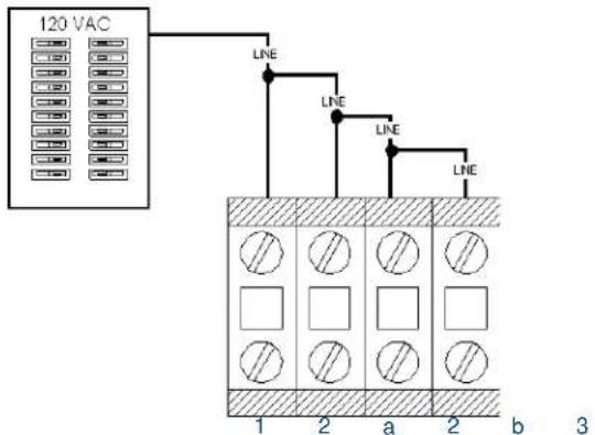
FIG. 9 RDA-ENC6B 120 VAC single-phase (2 W + G) wiring diagram
RDA-ENC6B 120/240 VAC Line Input (Single Phase)
FIG. 10 shows a 120/240 VAC single-phase (3 W + G) wiring diagram for the RDA-ENC6B line input terminal block.
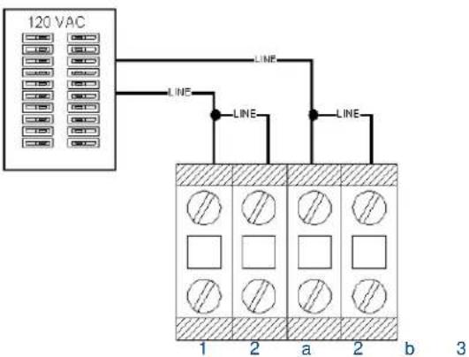
FIG. 10 RDA-ENC6B 120/240 VAC single-phase (3 W + G) wiring diagram
Connecting High-Voltage, Three-Phase Input Power and Loads
Follow these steps to wire high-voltage (120 VAC and 240 VAC), three-phase power connections (FIG. 11) to any of the AMX Lighting modules.

FIG. 11 High-voltage, three-phase input power
- Connect the green ground wire(s) to the copper ground lug on the enclosure. Ensure the ground wire is properly connected to earth ground.
- Connect the white neutral wire(s) to one of the terminals on the enclosure's neutral terminal block.
- Provide a separate neutral wire for each controlled zone.
- Connect the black line input from the electrical panel to the enclosure's line terminal. The line input terminal accepts a 0 AWG copper conductor.
- Connect load lines from the electrical devices to the Load terminals. Load 1 applies to dimmer 1, Load 2 applies to dimmer 2, and so on.
RDA-ENC6B 120/208 VAC Line Input (Three Phase)
FIG. 12 shows a 120/208 VAC three-phase (4 W + G) wiring diagram for the RDA-ENC6B line input terminal block.
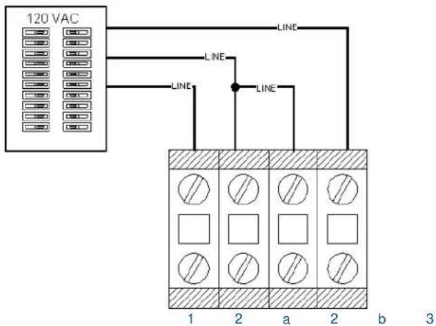
FIG. 12 RDA-ENC6B 120/208 VAC three-phase (4 W + G) wiring diagram
RDA-ENC6B Three Phase Line Input Connector Reference
FIG. 13 shows a sample RDA-ENC6 three phase (4 W + G) line input connector and dimmer references.
![graph TD A["1"] --> B["2"] B --> C["3"] C --> D["4"] D --> E["5"] E --> F["6"] G["Line input 1 feeds dimmer 1 and 4"] --> H["Line input 2a feeds dimmer 5"] H --> I["Line input 2b feeds dimmer 2"] I --> J["Line input 3 feeds dimmer 3 and 6"] K["Line input 1 feeds dimmer 1 and 4"] --> L["Line input 2a…](/content/2026/05/1068386/images/fd4e3dc135aafd55148a1e03c4969ba01fd638e563e903f9d6f8e4aa1570fbcc.jpg)
FIG. 13 RDA-ENC6B three-phase (4 W + G) line input connector and dimmer references
RDA-ENC6 and RDA-ENC12 Power Distribution and Line Input References
FIG. 14 shows the power distribution and line input references for the RDA-ENC6 and RDA-ENC12 line inputs.
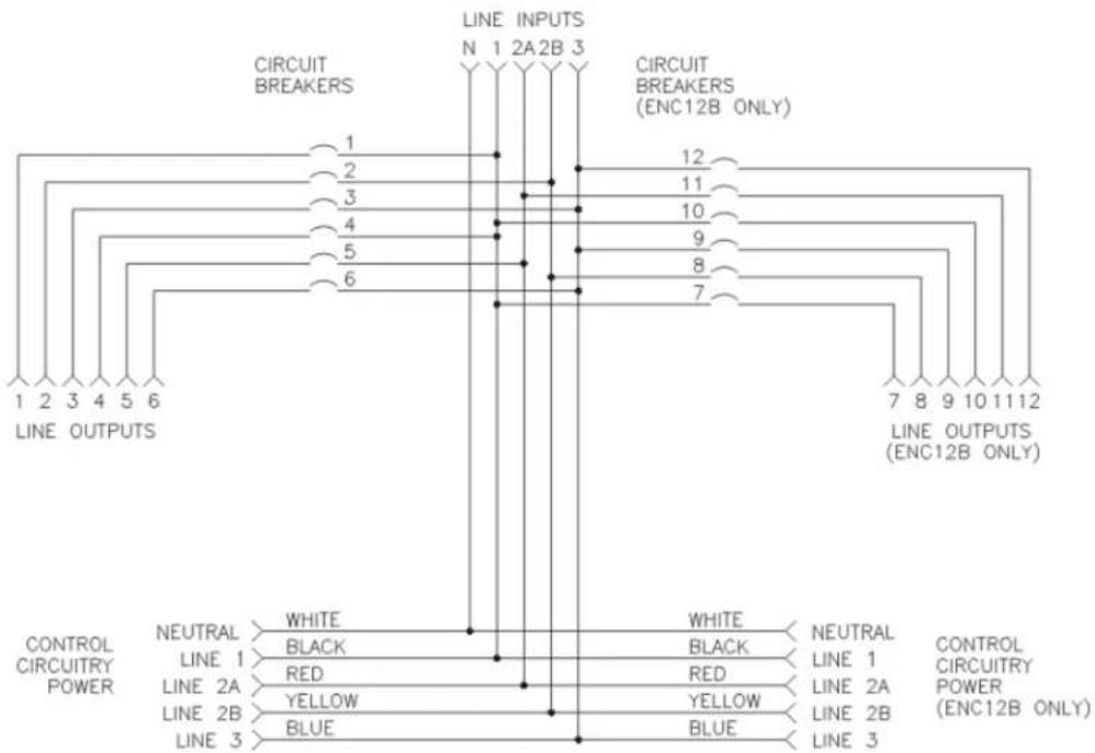
RDA-ENC6
Line input 1 feeds dimmers 1 and 4
Line input 2a feeds dimmer 5
Line input 2b feeds dimmer 2
Line input 3 feeds dimmers 3 and 6
RDA-ENC12
Line input 1 feeds dimmers 1 and 4, 7 and 10
Line input 2a feeds dimmer 5 and 11
Line input 2b feeds dimmer 2 and 8
Line input 3 feeds dimmers 3 and 6, 9 and 12
FIG. 14 RDA-ENC6 and RDA-ENC12 power distribution and line input reference references
Installing RDM Modules Into an Enclosure
Installing any of the RDM modules is an easy task. The individual modules are shipped with the four mounting screws enclosed.

To prevent possible personal injury or death, cut off power to the enclosure at the breaker box before attempting to install any AMX Lighting modules.
FIG. 15 illustrates the inside of an RDA-ENC6 enclosure and the mounting slots. The modules are positioned in the appropriate slot and secured using the supplied screws.
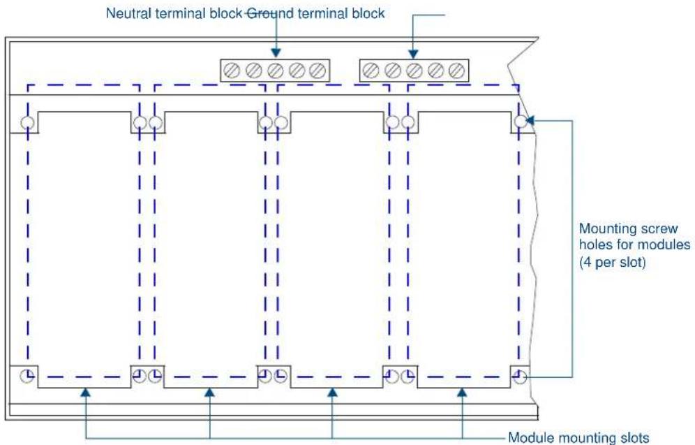
FIG. 15 Enclosure module mounting slots and mounting screw holes
The RDA-ENC2 enclosure contains a ground-terminating lug. The RDA-ENC4, RDA-ENC6, RDA-ENC6B, and RDA-ENC12B enclosures contain a neutral terminating block and a ground-terminating lug.
Low-Voltage Connections

All low-voltage connections must comply with Class 2 wiring codes.
The low-voltage area in the AMX Lighting controllers contain connections and DIP switches for AxLink, PROlink, dry closures, and module jack connectors. On the controller cards, low-voltage power for the board is supplied either by line power, optional auxiliary power supply (RDA-PSM), or the +12 VDC pin on the AxLink connector.
There is also a green status LED on the controller circuit board that blinks, according to the current operating status of AxLink and red LEDs, one for each of the external connectors for additional modules.
Figure 18 shows an example of the low-voltage connections, DIP switches and LEDs using the RDD-DM4 controller.
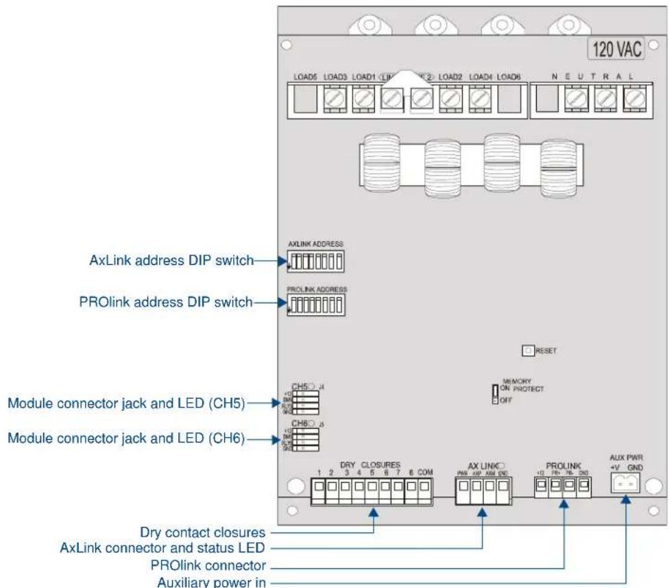
FIG. 16 Low-voltage connections and DIP switches
Module Connections
When connecting a dimming/switching module to a AMX Lighting controller, connect as shown in FIG. 17.

FIG. 17 Module connection to a con-troller card
Green Status LED Indicator
When you apply power to the AMX Lighting Control System, the green status LED notes its conditions:
- It is on full when power is applied to the control module.
- It blinks on and off when AxLink communication is present.
- It is off after default initialization is complete.
The LED indicator is located near the dry closure connector on the control module.
Red Status LED Indicators
The red LED's function is to indicate level. LED brightness increases as signal level increases from zero to 100. The LED indicator is located above each external load connector jack on the control module.
Configuring and Connecting PROlink
On all AMX Lighting controllers, DIP switch SW2 sets the PROlink pack number. The pack number is determined by the value of all the switch position settings. The following table shows the SW2 DIP switch positions and their values. The pack number assignment range is 1 through 10. The lighting system will not work if you assign a pack number outside of the range.
| SW2 DIP Switch Setting Values for PROlink | |
| Position Value | |
| 1 | 1 |
| 2 | 2 |
| 3 | 4 |
| 4 | 8 |
| 5 | n/a |
| 6 | n/a |
| 7 | n/a |
| 8 All lights on | |
- Power off the AMX Lighting enclosure at the breaker panel.
- Locate the SW2 DIP switch on the controller circuit card (marked PROLINK ADDRESS), and set the pack number using the values shown in the proceeding table. The pack number must be 1 to 10.

Assign pack 1 for all communications, diagnostics, and feedback response.
-
FIG. 18 shows how to wire the PROlink connector to a PROlink wall panel.
-
Connect the four-pin PROlink male connector to the four-pin female PROlink connector on the AMX Lighting controller.
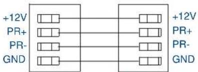
Radia PROlink connectorPROlink wall panel
FIG. 18 PROlink wiring diagram
- Apply power to the AMX Lighting controller at the breaker panel.
FIG. 19 shows an example of how to interconnect two AMX Lighting RDD-DM4 controllers and a PROlink wall panel.
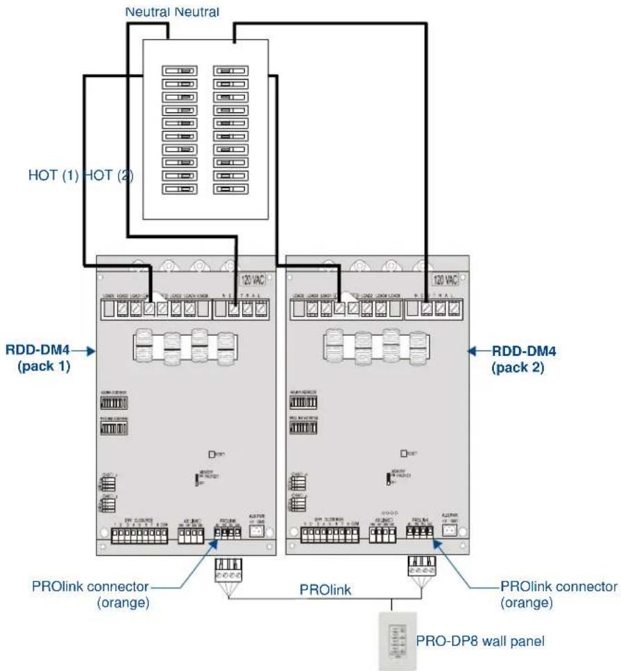
FIG. 19 PROlink configuration sample
Configuring and Connecting AxLink
On all AMX Lighting controllers, DIP switch SW1 sets the AxLink device number. The device number is determined by the value of all the switch position settings. The following table shows the SW1 DIP switch positions and their values. The device number assignment range is 1 through 255.
| SW1 DIP switch setting values for AxLink | |
| Position Value | |
| 1 | 1 |
| 2 | 2 |
| 3 | 4 |
| 4 | 8 |
| 5 | 16 |
| 6 | 32 |
| 7 | 64 |
| 8 128 | |
- Power off the enclosure unit at the breaker panel.
- Locate the SW1 DIP switch (AxLink ADDRESS) on the controller circuit card and set the device number using the values shown in the proceeding table.
- Connect the four-pin AxLink male connector into the four-pin female AxLink connector on the controller circuit card. FIG. 20 shows how to wire the AxLink connector to a Central Controller system.

FIG. 20 AxLink wiring diagram
- Apply power to the controller module at the breaker panel.
Connecting dry closures
AMX Lighting controller modules contain eight connections for dry contact closures, and one common reference point. FIG. 21 shows the standard wiring configuration for the 9-pin dry closure connector.

FIG. 21 9-pin dry closure connector (standard configuration)
Each contact closure connection (1 through 8) is pre-programmed with a default preset. The following table shows the default presets for each contact closure.
| Dry closure default presets | |
| Contact closure | Default function |
| 1 Channel 1 at 100% | in 1 second* |
| 2 Channel 2 at 100% | in 1 second* |
| 3 Channel 3 at 100% | in 1 second* |
| 4 Channel 4 at 100% | in 1 second* |
| 5 Channel 5 at 100% | in 1 second* |
| 6 Channel 6 at 100% | in 1 second* |
| 7 Pack on (channels | 1-6)* |
| 8 Pack off (channels | 1-6)* |
| *All other channels are undefined. | |
Default Mode (Reset)
Default mode is resetting the AMX Lighting module values to zero and the module then begins to function on the values you previously programmed into the module. If you experience problems after installing a lighting system, you may need to reset the controller module to default mode. Then, you should be able to determine if there is a problem with the connections, programming, and/or dimming.
To reset a AMX Lighting controller to default mode:
- Power off the AMX Lighting enclosure at the circuit breaker panel.
- Disconnect all AxLink and PROlink cables from the controller module.
- Connect a jumper to the dry contact closures 1 through 8 and to ground as shown in FIG. 22.

FIG. 22 9-pin dry closure connector set to default mode
- Power up the controller enclosure and wait for the controller's green status LED to go off after approximately 1 minute.
- Using a non-conductive rod or wooden one-quarter inch dowel rod (approximately 12" long) press the RESET button located on the controller module circuit board.
- At the breaker panel, remove power from the controller enclosure.
- Remove the jumpers from the dry contact closure connector.
- Reconnect the AxLink and PROlink connections.
- Power up the controller enclosure.
External Power
The following table lists the modules that use most of the operating power a AMX Lighting control module can supply. They may require extra power from the AxLink connection, or an external power supply connected to the control module or module(s) when using multiple modules.
| External Modules | ||
| RDM-HSW R | RDM-MR RDM | SWM |
| RDM-2HSW | RDM-2MR RDM | -2SWM |
| RDM-3HSW | RDM-3MR RDM | -3SWM |
| RDM-HFDB | RDM-MR35 RDM | -DPSM |
| RDM-HDC R | RDM-MR60 | |
If extra power is required, connect an auxiliary 12 VDC power supply as shown in FIG. 23.
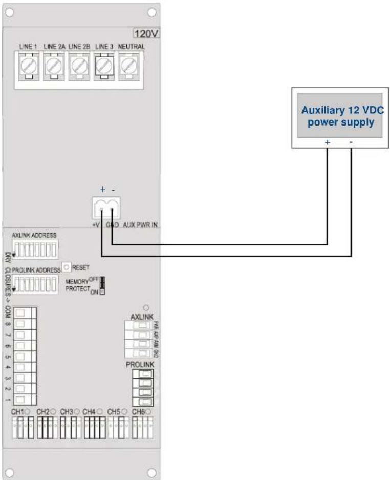
FIG. 23 Auxiliary power connection
Compatible Ballast Information
This section contains descriptions and manufacturer information on AC-controlled magnetic ballasts, AC-controlled electronic ballasts, DC-controlled electronic ballasts, and ballast interfaces that are compatible with the AMX Lighting Control System.

WARNING
The ballasts listed in this section have been reported to AMX by other parties to be compatible with AMX Lighting dimming systems. AMX has not tested every ballast/dimmer combination, and cannot verify either compatibility or correct operation. AMX does not specifically recommend any particular ballast make or model. Contact AMX for information regarding ballasts not listed.
AC-Controlled Magnetic Ballasts
AC-controlled magnetic ballasts are simple circuits that smooth out the raw AC power to lamps. They should not be used in presentation dimming applications because they do not perform well in lower dimming ranges.

NOTE
AC-controlled magnetic ballasts are not recommended for critical lighting control.
AC-Controlled Electronic Ballasts (3-Wire Ballasts)
AC-controlled electronic ballasts deliver smooth flicker-free operation down to 1% brightness at low light levels for some models (under ideal conditions). The ballast receives an AC dimming signal and interprets the appropriate response to the lamps. AMX Lighting can control AC-style ballasts using the RDM-FDB satellite module.
The following table lists compatible AC-controlled electronic ballasts.
| AC-controlled electronic ballasts (3-wire ballasts) | |||
| Manufacturer Style | Model Volts AMX | Lighting modules | |
| Lutron Hi-Lume FDB AI | models 120 RDM-HFDB, RDM-MDM | ||
| Lutron Hi-Lume FDB AI | models 277 RDM-HFDB, RDM-MDM | ||

NOTE
The AMX Lighting RDD-DM4 can control Lutron FDB ballasts using Lutron interface GRX-FDBI or HP2.
DC-Controlled Electronic Ballasts (4-Wire Ballasts)
The DC-controlled Electronic Ballasts track a 0-10 or 0-12 VDC channel for dimming and an AC switch channel for on/off. This ballast design is better than magnetic, but many stop dimming at about 20% brightness. That's fine for energy management and secondary lighting zones, but not for primary lighting that requires precision, low-level dimming control.
The following table lists compatible DC-controlled electronic ballasts.
| DC-controlled electronic ballasts (4-wire ballasts) | ||||
| Manufacturer Style Model Volts A | MX Lighting modules | |||
| Advance Mark VII All models 120 RDM-HDC | ||||
| Advance Mark VII All models 277 RDM-HDC | RDM-DCRDM-2DCRDM-3DC | |||
| Lightolier PowerSpec HDF See Ballast interfaces | ||||
| Magnatek TRIAD B232SR120V20 120 RDM-HDC | ||||
| Magnatek TRIAD B232SR277V20 277 RDM-HDC | ||||
| Motorola Helios M2-RN-T8-10C-120 120 RDM-HDC | ||||
| Motorola Helios M2-RN-T8-10C-277 277 RDM-HDC | ||||
| Prescolite Intelect | PUV series | 120 RDM-HDC | ||
| Prescolite Intelect | PUV series | 277 RDM-HDC | ||
Ballast Interfaces and 2-Wire Ballasts
In some cases, dimmers are wired to ballast interfaces (provided optionally by lighting suppliers), rather than directly to the ballasts. A few interfaces are driven from a standard AMX Lighting incandescent channel, while most use FDB dimming configurations.
The following table lists compatible ballast interfaces.
| Ballast Interfaces and 2-Wire Ballasts | |||||
| Manufacturer | Style | Model | Volts | AMX Lighting modules | Note |
| Advance | Mark X | All models | 277 | RDM-INC | |
| Lightolier | DA10 HDFDA20HDF | PowerSpec HDF | 277 | RDD-DM4, RDD-DM6, RDM-MDM,RDM-INC, RDM-2INC, and RDM-INC50 | 1 |
| Lutron | HP-2/4/6 Interfaces | HiLume FDB | 120 | RDD-DM4, RDD-DM6, RDM-MDM,RDM-INC, RDM-2INC, and RDM-INC50 | 2 |
| Lutron | GRX-FDBI | HiLume FDB | 120 | RDD-DM4, RDD-DM6, RDM-MDM,RDM-INC, RDM-2INC, and RDM-INC50 | 3 |
| Prescolite | CIB Interface | Intelect ballasts | 120 | RDD-DM4, RDD-DM6, RDM-MDM,RDM-INC, RDM-2INC, and RDM-INC50 | 4 |
| Prescolite | CIB Interface | Intelect ballasts | 277 | RDD-DM4, RDD-DM6, RDM-MDM,RDM-INC, RDM-2INC, and RDM-INC50 | 4 |
| Notes:1. The Lightolier ballasts require a proprietary DC-signal interface (including low-level trim). The AMX Lighting controller module handles load power.2. The Lutron HP-2, 4, and 6 interfaces accept 120 VAC input. The load can be 120/277 VAC (including low-level trim). Interface includes power control to ballasts.3. The Lutron GRX-FDBI accepts 120 VAC input. The load must be 120 VAC. Interface includes power control to ballasts.4. The Prescolite ballast interfaces are optional. The AMX Lighting controller handles load power. | |||||
Glossary
Air Gap Switch - A relay or mechanical switch that physically separates a load from the power feed, resulting in an air gap between the contacts. An air gap is a deliberate and noticeable space or disruption in a circuit causing an open condition.
AxLink - A four-wire data bus used to transmit and receive data from the AxLink Central Controller to any of 255 devices on the system. An AxLink address designates which of 255 possible devices assigned to the main AxLink is assigned to the Radia Lighting controller.
Ballast - An electrical device used in fluorescent and HID fixtures. It furnishes the necessary starting and operating characteristics to the fluorescent lamp for proper performance. Not all ballasts can dim lights. Fluorescent ballasts may contain the following:
- Ballast reactor
- Auto-transformer
● Power factor correction circuit
Breaker - An automatic switch that stops the flow of electric current in a suddenly overloaded or otherwise abnormally stressed electric circuit. A circuit breaker is an air gap switch.
BTU - The acronym for British Thermal Unit. This term also applies to the amount of heat required to increase the temperature of a pound of water one degree Fahrenheit. It is used to measure the thermal or heat-producing effect of a device.
CFL Lamp - An acronym for Compact Fluorescent Lamp (a type of fluorescent lamp).
Channel (Radia Lighting) - The Radia Lighting processor's dimming engine recognizes six independent levels and paths of output control. These control paths are called dimming channels or just channels. Each Radia Lighting master controller (pack) has six channels of control. AxLink channels are used in Axcess programming and apply to operation using an AxLink system.
Choke - A device used in electric circuits to oppose changes in the magnitude or direction of current flow. A choke device reduces noise caused by lamp filaments and is also known as a "dc-buzzing coil."
Contact Closure - A circuit is formed when the two contacts of an open circuit are brought together. The Radia Lighting master controller uses TTL logic levels normally pulled High to 5v. A closure to ground pulls the level to logic Low and is read as a closure. Each of the eight closure inputs is independently operated and controlled.
Contactor - A type of relay that accepts large current loads greater than 20 Amps, usually with a 120-volt primary coil. A contactor is helpful in allowing a 120-volt control signal to switch a large circuit at 277 volts.
Control Card, also Card - A Radia Lighting master controller on a standard 2.75" x 10" enclosure plate that is capable of six channels of control, an AxLink connection, a PROlink connection, and a dry closure connection.
This applies to Radia Lighting models RDC-DC/120, RDC-DC/240, RDC-DC/277, RDC-PDC/120, and RDC-PDC/240 only.
Control Current - The current used by a dimmer or switch to perform its function. Each Radia Lighting controller supplies this current to its control ports and each Radia Lighting module uses and requires this current in order to operate the dimmer or switch.
Control Port - The four-pin connector on the Radia Lighting controller used for electrical control of the dimmer (or switch) is called the Control Port. All modules connect to a control port to operate. There is a maximum of six ports on the Central Controller.
Controller - A Radia Lighting device capable of six channels of control, an AxLink connection, PROlink connection, and a dry closure connection. A controller could also be the integrated module.
This applies to Radia Lighting models RDC-DC/120, RDC-DC/240, RDC-DC/277, RDC-PDC/120, RDC-PDC/240, RDD-DM4/120, RDD-DM4/240, RDD-DM4/277, RDD-DM6/120, RDD-DM6/240, and the RDD-DM6/277.
Curve - Used to match the channel level setting with the dimmer output. At a level of 50%, different curves would cause different dimmer output voltages. A curve can be used to govern the amount of dimming control relative to the level setting allowing for uniform dimming between different loads.
Dimmer - A device located in an enclosure that is capable of dimming a light or electric circuit. Each dimmer is rated by Wattage and Voltage.
Electronic Transformer - A transformer that reduces the voltage output when the primary voltage of the transformer is reduced. This causes the secondary output of the transformer to reduce its voltage through electronic means. Electronic transformers should be specifically designed for standard dimming. Some electronic transformers are not dimmable or exhibit poor dimming performance.
Enclosure - The UL-approved box into which Radia Lighting control cards, modules, and accessories are installed.
Fade - A steady change in lighting levels expressed in seconds of time. A fade can encompass an individual or group of dimmers. A preset can be set to fade into another preset where one or more lights dim, increase in brightness, or stay at the same level.
Fade Rate - The amount of time it takes to change from one preset to another, or from one level to another, and is expressed in seconds.
FDB Ballast - FDB ballast are made by Lutron Electronics. The ballast are controlled using a switched hot and a dimmed hot in combination. An RDM-FDB module is one that dims FDB ballast with an AC current using a solid state dimmer and a switched feed through a relay. Lutron ECO-10 ballast are also controlled in the same manner.
Fluorescent Lights or Lamps - A lamp that produces visible light by fluorescence (producing light when acted upon by radiant energy). The lamp consists of a glass tube, the inner wall of which is coated with a material that fluoresces when bombarded with secondary radiation generated by a gaseous discharge within the tube. Control systems affect the ballast, not the lamp.
Halogen Lights or Lamps - A halogen lamp is a type of incandescent light source that uses halogen gas in an enclosed capsule. It uses the halogen regenerative cycle to prevent blackening of the lamp envelope during life. Halogen lamps are dimmed using a standard incandescent dimmer.
Integrated Dimmer Module - A Radia Lighting device that contains both a six-channel master controller and dimmers on the same package. They will have a PROlink address and can be on AxLink. The RDD-DM4/ series and the RDD-DM6/ series are integrated dimmer modules, and they all take up two module spaces.
Level Time - A Radia Lighting default parameter. Level time is the time it takes for a dimmer to reach its assigned level after receiving a level command.
Line - The wire or circuit that supplies power to a dimmer or electrical device. The line wire often comes from an electrical circuit breaker panel.
Load - The particular device or resistance of a device to the power being delivered. Also the total amount of devices connected to the output of a dimmer or switch. The load wire connects from the dimmer to the lamps. Lights are common loads along with motors and other power equipment.
Master Controller - A Radia Lighting device capable of six channels of control, an AxLink connection, PROlink connection, and a dry closure connection. Same as Controller.
Magnetic Transformer - A coil-core transformer that dims a light when the primary voltage from the transformer is reduced, causing the secondary output of the transformer to reduce its voltage through magnetic coupling. Incandescent dimmers can be used to control magnetic transformers.
Metal Halide - A HID lamp that uses radiation of metal halides in combination with metallic vapors like mercury. Not normally a dimmable lamp, and requires long start up times.
Module - A Radia Lighting dimmer or switch designed for installation in a Radia Lighting enclosure. Most modules are on a standard 2.75" x 10" enclosure plate or heatsink; some modules require two standard spaces.
Neon - A light source made from high voltage excitation of neon gas enclosed in a glass tube. Neon is a type of lamp that uses a step-up transformer to operate the lamp. Neon transformers can be dimmed.
Pack - A Radia Lighting Central Controller consisting of six channels of control on the PROlink control bus. Pack settings of 1 through 10 allow for 10 six-channel packs for a total of 60 channels of control on one PROlink bus.
Peak Switch - A switch that opens or closes at the height of the AC cycle, as opposed to the zero-cross point of the AC cycle.
Phase Dependent - A dimmer module must have its supply voltage on the same phase (A, B, or C) as the electricity supplied to the controller. Only dimmer modules are phase-dependent.
Port (Control Port) - A four-pin connector used to connect a Radia Lighting module to a controller. There is a maximum of six ports on the Central Controller.
Power Consumption Rating - An amount of energy used by a device to perform its function at maximum load. Radia Lighting devices have power consumption ratings expressed in milliamps (mA). Radia Lighting controllers provide this power to operate the modules and can also get more power from external power supplies.
Power Rating - Ratings expressing the maximum load capacity of a module, dimmer, or switch. Radia Lighting power ratings are based on UL testing and approvals.
Preset - A preset is a stored scene. Presets can consist of a single dimmer or any combination of dimmers as a group of stored values. Radia Lighting presets allow a dimmer or any combination of dimmers to be excluded from a preset.
Preset Fade Time - A Radia Lighting default parameter. The amount of time it takes for one preset to begin to fade out and another preset to completely fade in.
Preset Ramping - The active preset can be ramped to a different level while retaining the proportions and integrity of the preset scene. A preset can be dimmed so that all levels are zero and recovered or brought to full brightness and the dimmed back down to the original settings.
PROlink - A four-wire data bus used to transmit and receive data from pack to pack. A PROlink address designates which six channels of control will be assigned to a pack, up to 10 pack addresses and 60 channels of control.
Ramp - The increasing or decreasing of a light level on a continuous grade or increment.
Ramp Rate - The time it takes for a dimmer or group of dimmers to go from their present level to full light level or zero light level via a ramp command, expressed in seconds of time.
If a dimmer is at 50%, then a 5-second ramp rate means it takes 5 seconds to go from 50% to 0, or from 50% to 100%. If a dimmer is at 75%, then a 5-second ramp rate means it takes 5 seconds to go from 75% to 0, or from 75% to 100%.
Relay - A controlled device that interrupts or connects a circuit.
Satellite Module - Any Radia Lighting dimmer or switch module (RDM-series).
Scene - The condition or status of all dimmers in a designated area or zone. A stored scene is a preset. A preset recalled and then changed becomes a scene.
Slot - A single space in a Radia Lighting enclosure numbered from left to right starting at #1. This is used to describe which space in an enclosure a module is located or installed.
Solid State Dimmer - A type of dimmer that uses electronic semiconductors and other solid-state electronic devices to control the dimming of a lamp or ballast.
Space - An enclosure dimension of 2.75" x 10" capable of installing a Radia Lighting module.
Switch - A device that breaks and connects an electrical circuit.
Three Phase Power - A power system that combines three hot powered leads and one neutral line. Each line is 120° out of phase with each other. Common building and residential electrical panels provide three phase power where the potential difference between any phase and neutral is 120 VAC. The Radia Lighting PRO enclosure accepts three phase power.
Transformers - A device for altering the voltage of an AC supply. Transformers are commonly used to step down a higher voltage to a lower voltage used by the lamp. Transformers can also be used to step up a voltage such as a neon transformer that outputs thousands of volts from a 120 VAC feed.
Undefined (level) - A level setting that causes a channel to be excluded from a preset.
Zero Cross - The point where the AC waveform is at zero potential to ground is called the zero cross point. The zero-cross point is used as a common electrical reference in a dimming circuit and provides a synchronized reference point for opening or closing a relay. The zero-cross point is determined by the phase of the line input power and neutral.
Zone - A zone is an area of lighting under independent control. It can be made up of one or more dimmers. A lighting zone can be one table lamp or an entire corridor. Common usage has one dimmer to one zone, but a lighting zone can be made up of many dimmers.
AMX
It's Your World - Take Control™
- OPERATION/REFERENCE GUIDE
- RADIA
- LIGHTING CONTROL SYSTEM
- AMX LIMITED WARRANTY AND DISCLAIMER
- TABLE OF CONTENTS
- INTRODUCTION ...... 1
- INSTALLATION 5
- COMPATIBLE BALLAST INFORMATION ....19
- GLOSSARY 21
- INTRODUCTION
- FEATURES
- APPLICATIONS
- CONTROLLERS
- AMX LIGHTING CONTROL EQUIPMENT
- INSTALLATION
- SPACE REQUIREMENTS
- CONDUIT
- ENCLOSURE DIMENSIONS
- RDA-ENC2, -ENC4, AND -ENC6 ENCLOSURE AND DIMENSIONS
- RDA-ENC6B AND RDA-ENC12B ENCLOSURES AND DIMENSIONS
- MOUNTING AMX LIGHTING ENCLOSURES
- HIGH-VOLTAGE CONNECTIONS
- CONNECTING HIGH-VOLTAGE, SINGLE-PHASE INPUT POWER AND LOADS
- RDA-ENC6B 120 VAC SINGLE PHASE LINE INPUT
- RDA-ENC6B 120/240 VAC LINE INPUT (SINGLE PHASE)
- CONNECTING HIGH-VOLTAGE, THREE-PHASE INPUT POWER AND LOADS
- RDA-ENC6B 120/208 VAC LINE INPUT (THREE PHASE)
- RDA-ENC6B THREE PHASE LINE INPUT CONNECTOR REFERENCE
- RDA-ENC6 AND RDA-ENC12 POWER DISTRIBUTION AND LINE INPUT REFERENCES
- RDA-ENC6
- RDA-ENC12
- INSTALLING RDM MODULES INTO AN ENCLOSURE
- LOW-VOLTAGE CONNECTIONS
- MODULE CONNECTIONS
- GREEN STATUS LED INDICATOR
- RED STATUS LED INDICATORS
- CONFIGURING AND CONNECTING PROLINK
- CONFIGURING AND CONNECTING AXLINK
- CONNECTING DRY CLOSURES
- DEFAULT MODE (RESET)
- EXTERNAL POWER
- COMPATIBLE BALLAST INFORMATION
- AC-CONTROLLED MAGNETIC BALLASTS
- AC-CONTROLLED ELECTRONIC BALLASTS (3-WIRE BALLASTS)
- DC-CONTROLLED ELECTRONIC BALLASTS (4-WIRE BALLASTS)
- BALLAST INTERFACES AND 2-WIRE BALLASTS
- GLOSSARY
Brand : AMX
Model : RDM-2INC
Category : Dimmer