
V-9924C - Sound alarm Valcom - Free user manual and instructions
Find the device manual for free V-9924C Valcom in PDF.


| Product Type | Sound alarm |
| Brand | Valcom |
| Model | V-9924C |
| Dimensions (H x W x D) | 6 x 4 x 3 inches |
| Weight | 1 lb |
| Power Supply | 12-24V DC |
| Sound Level | 100 dB at 1 meter |
| Frequency | Adjustable tone (typically 800-2000 Hz) |
| Mounting Type | Surface mount (wall or ceiling) |
| Material | High-impact ABS plastic |
| Weatherproof Rating | IP44 (splashproof) |
| Operating Temperature | -10°C to 50°C |
| Current Consumption | 200 mA max |
| Connection Type | Screw terminals |
| Compliance | UL 464, FCC Part 15 |
| Primary Function | Audible alert for security or paging systems |
| Maintenance | Wipe with a damp cloth; check wiring annually |
| Safety | Disconnect power before cleaning or servicing |
| Spare Parts | None user-serviceable; contact Valcom for warranty |
| Warranty | 1 year limited |
Frequently Asked Questions - V-9924C Valcom
User questions about V-9924C Valcom
0 question about this device. Answer the ones you know or ask your own.
Ask a new question about this device
Download the instructions for your Sound alarm in PDF format for free! Find your manual V-9924C - Valcom and take your electronic device back in hand. On this page are published all the documents necessary for the use of your device. V-9924C by Valcom.
USER MANUAL V-9924C Valcom
V-9924C COMMON AUDIBLE RINGING UNIT
GENERAL
The Common Audible Ringing Unit provides an audible signal over the paging system when there is an incoming call. It is used between a telephone system and the public address system.
SPECIFICATIONS
Activation
• 1A2 Bell/Buzzer ICM
- PABX Station Port
- Contact Closure
Features
- Activates via ringing voltage, buzzer voltage or contact closure
- Capable of switching signal to three zones simultaneously
• Uses standard 1A2 key system voltages
• Each zone is equipped with a 5 Watt amplifier and volume control - Screw terminal connection
- Compact size, can be mounted on wall or in cabinet
- Automatically switches paging speakers from paging system to audible signal of the V-9924C during the ring interval of the incoming call
- Variable pitch control
- Two auxiliary contact closures
Other Materials Required
-24VDC power supply
• Cat 3 or 5 twisted pair telephone cable
- Mounting screws and hardware

Dimensions/Weight
- 8.20" H x 4.55" W x 2.30" D
(20.83cm H x 11.56cm W x 5.84cm D)
• 1.3 lbs. (0.59kg)
Power Requirements
The V-9924C requires a -24VDC "B" battery and draws 50mA idle and 300mA maximum operating.
Signal Requirements
The V-9924C requires interrupted ringing or buzzer voltage or dry contact closure to operate. The output of the V-9924C will follow the interruptions of the input. The ringing voltage should be approximately 90VAC and the current requirement would be 8mA. The buzzer voltage should be approximately 18VAC and the current requirement would be 10mA. The V-9924C pulls approximately 3mA through a dry contact closure for activation. Ringing and buzzer voltages cannot be applied simultaneously. Use only one method of activation.
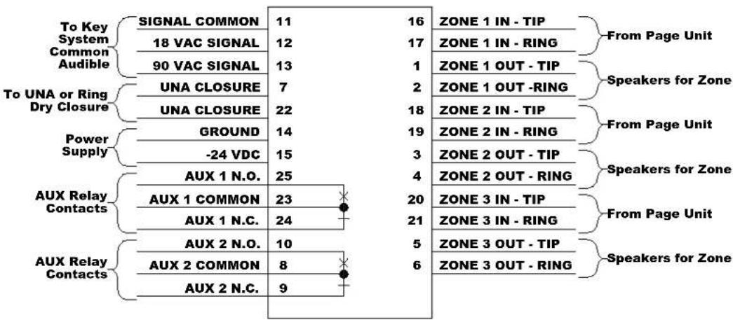
FIGURE 1 - SIMPLIFIED BLOCK DIAGRAM
INSTALLATION
Precautions
Failure to observe the following precautions could result in damage to the V-9924C and other equipment.
a. Unplug the power supply when connecting the power leads and signal leads to the unit. These leads are brought in on adjacent terminals. Accidental bridging of these two terminals could damage the equipment.
b. Use pared crossconnect wire for all voice connections and voltages.
c. Set all volume controls to their minimum (counter clockwise) level.
Mounting
Remove the metal mounting plate from the rear of the V-9924C enclosure. Using two #6 3/4" wood screws, mount the plate in a vacant space on the backboard with the telephone system common equipment. Both mounting holes must be utilized to insure secure mounting of the unit (see Figure 1A).
Open the V-9924C enclosure to access connections and option switches. Slide the rear of the unit (contains the board) onto the mounting plate and lock in place with screw provided. Make connections.
Signaling Connections
The V-9924C can be activated via ringing voltage, buzzer voltage or a dry contact closure. When used with buzzer voltage, apply one side of the pair to SIG COMMON (pin 11 or 26) and the other side of the pair to 18VAC SIG (pin 12 or 27). For ringing voltage connections, put one side of the pair on SIGCOMMON (pin 11 or 26) and the other side of the pair to 90VAC SIG (pin 13 or 28).
The V-9924C can also be activated by connecting one side of a dry contact closure to pin 7 and the other side of the dry closure to pin 22.
Speaker Connections
The V-9924C Common Audible Ringing Unit is capable of switching up to three zones of speakers to the audible signal generated by the unit. The device is intended to be placed in series with the speakers. Zone 1 IN (pins 16 and 17) are connected to the speaker/zone output leads of the page control. Zone 1 OUT (pins 1 and 2) are connected to the speakers. Zones 2 and 3 hook up in a similar fashion. Refer to Figure 2B for pin numbers.
Power Connections
Connect -24VDC from the power supply to pin 15 or 30 on the crossconnect block and ground to pin 14 or 29.
Contact Closure
Two form C auxiliary contact closures are provided on the V-9924C. These contacts follow the input cadence and may be used for special applications. The contact ratings are 1 Amp at 24VDC.
Set Up
After all connections are complete and double checked, apply voltage to the unit. Place a call to the telephone system and while ringing or buzzer is being applied to the unit or when the dry contact closure closes, adjust the volume of each zone by turning the volume control clockwise for each zone. Replace cover when all connections and adjustments are complete and lock in place using the #6 1/2" screws provided.

FIGURE 1A
OPERATION
Figure 3 shows a V-9924C simplified schematic. When the V-9924C is idle, 1T IN is shorted to 1T OUT, 1R IN is shorted to 1R OUT, 2T IN is shorted to 2T OUT, 2R IN is shorted to 2R OUT, 3T IN is shorted to 3T OUT and 3R IN is shorted to 3R OUT.
A signal appearing at the T IN, R IN terminals will also appear at the T OUT, R OUT terminals for each zone.
Signaling
When ringing or buzzer voltage appears at the signaling input leads of the V-9924C or UNA closure pins are connected, relays are energized and the 1T OUT, 1R OUT, 2T OUT, 2R OUT, 3T OUT, and 3R OUT leads are switched to the outputs of three 5 Watt amplifiers (one for each zone). At the same time, the electronic warble tone is connected to the input of each of the amplifiers and the warble signal (which follows the interrupted ringing pattern) is broadcast to all of the speakers. Each zone has its own volume control so the volume can be set to a comfortable level.
Pitch Control
Dipswitches have been provided to vary the pitch of the warble ring tone should a different pitch be desired. Generally, this control does not require adjustment (see Figure 2B). If adjustment is necessary, see chart to select desired pitch (see Figure 2A).
| BIT 1 | BIT 2 | |
| LOW | OFF | OFF |
| MED | OFF | ON |
| HI | ON | OFF |
| DEFAULT | ON | ON |
FIGURE 2A
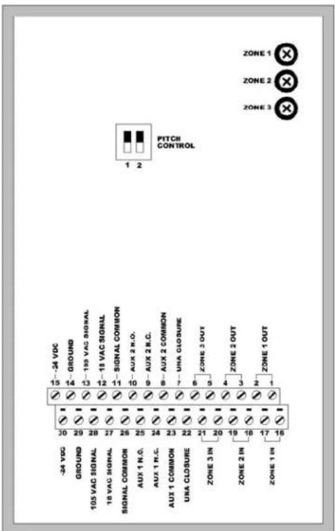
FIGURE 2B
TECHNICAL ASSISTANCE
When trouble is reported, verify power is being supplied to the unit, buzzer, ringing voltage or contact closure appears at the unit and that there are no broken connections at the screw terminals. To effectively test the unit, a VOM and a lineman's test set will be required. Use the VOM to check for voltage from the power supply and to verify that buzzer or ringing is coming from the telephone system. The lineman's test set can be used to check for the warble tones on the T OUT and R OUT leads to the speaker. If a spare unit is available, continue to troubleshoot by substituting a spare unit for the suspected unit.
Assistance in troubleshooting is available from the factory. When calling, you should have a VOM, a telephone test set and be calling from the job site. Call (540) 563-2000 and press 1 for Technical Support or visit our website at http://www.valcom.com.
The V-9924C is not field repairable. Valcom equipment contains no user serviceable parts inside. Valcom, Inc. maintains service facilities in Roanoke, VA. Should repairs be necessary, attach a tag to the unit clearly stating your company name, address, phone number, contact person and the nature of the problem. Send the unit to:
Valcom, Inc.
Repair and Return Dept.
5614 Hollins Road
Roanoke, VA 24019-5056
![graph TD A["POWER SUPPLY "B BATT""] --> B["GND 14,29 -24VDC"] B --> C["PITCH CONTROL"] C --> D["TONE GENERATION"] D --> E["RING DETECTION"] E --> F["R8 VOLUME ZONE 1"] E --> G["R12 VOLUME ZONE 2"] E --> H["R16 VOLUME ZONE 3"] F --> I["K3"] G --> J["K2"] H --> K["K1"] I --> L["16 ZONE 1 IN…](/content/2026/05/1068373/images/5b4b0ddc86c80d7af811b74200d0956dc4aa913bbbd425656cf0f9607fa3626a.jpg)
FIGURE 3 – SIMPLIFIED SCHEMATIC
VALCOM LIMITED WARRANTY
Valcom, Inc. warrants its products to be free from defects in materials and workmanship under conditions of normal use and service for a period of one year from the date of shipment. The obligation under this warranty shall be limited to the replacement, repair or refund of any such defective device within the warranty period, provided that:
- inspection by Valcom, Inc. indicates the validity of the claim;
- the defect is not the result of damage, misuse, or negligence after the original shipment;
- the product has not been altered in any way or repaired by others and that factory sealed units are unopened (a service charge plus parts and labor will be applied to units defaced or physically damaged);
- freight charges for the return of products to Valcom are prepaid;
- all units 'out of warranty' are subject to a service charge. The service charge will cover minor repairs (major repairs will be subject to additional charges for parts and labor).
This warranty is in lieu of and excludes all other warranties, expressed or implied and in no event shall Valcom, Inc. be liable for any anticipated profits, consequential damages, loss of time or other losses incurred by the buyer in connection with the purchase, operation, or use of the product.
This warranty specifically excludes damage incurred in shipment. In the event a product is received in damaged condition, the carrier should be notified immediately. Claims for such damage should be filed with the carrier involved in accordance with the F.O.B. point.
Headquarters:
Valcom, Inc.
5614 Hollins Road
Roanoke, VA 24019-5056
Phone: (540) 563-2000
FAX: (540) 362-9800
- V-9924C COMMON AUDIBLE RINGING UNIT
- GENERAL
- SPECIFICATIONS
- ACTIVATION
- FEATURES
- OTHER MATERIALS REQUIRED
- DIMENSIONS/WEIGHT
- POWER REQUIREMENTS
- SIGNAL REQUIREMENTS
- INSTALLATION
- PRECAUTIONS
- MOUNTING
- SIGNALING CONNECTIONS
- SPEAKER CONNECTIONS
- POWER CONNECTIONS
- CONTACT CLOSURE
- SET UP
- OPERATION
- SIGNALING
- PITCH CONTROL
- TECHNICAL ASSISTANCE
- VALCOM LIMITED WARRANTY
Brand : Valcom
Model : V-9924C
Category : Sound alarm