
SDV9201K - TV antenna PHILIPS - Free user manual and instructions
Find the device manual for free SDV9201K PHILIPS in PDF.


| Product Type | Indoor TV Antenna |
| Brand | Philips |
| Model | SDV9201K |
| Dimensions (W x H x D) | 10.2 x 15.8 x 4.5 in (260 x 400 x 115 mm) |
| Weight | 1.2 lbs (0.55 kg) |
| Power Supply | 5V DC via USB (adapter included) |
| Frequency Range | VHF 88-108 MHz, UHF 470-698 MHz |
| Gain | 30 dB (max) |
| Impedance | 75 Ohm |
| Cable Length | 10 ft (3 m) |
| Mounting | Desk stand or wall mount |
| Color | Black |
| Reception | Digital TV (ATSC), 4K/HD ready |
| Amplifier | Built-in, with on/off switch |
| Operating Temperature | 14°F to 122°F (-10°C to 50°C) |
| Certifications | CE, RoHS |
| Warranty | 1 year |
Frequently Asked Questions - SDV9201K PHILIPS
User questions about SDV9201K PHILIPS
0 question about this device. Answer the ones you know or ask your own.
Ask a new question about this device
Download the instructions for your TV antenna in PDF format for free! Find your manual SDV9201K - PHILIPS and take your electronic device back in hand. On this page are published all the documents necessary for the use of your device. SDV9201K by PHILIPS.
USER MANUAL SDV9201K PHILIPS
natural_image
Black and white photo of a mounted antenna or antenna device with multiple blades and a mesh grille (no text or symbols visible)PHILIPS
3 Safety Instructions
4 Assembly and Installation
5 Aiming the Antenna
5 DTV Tuner Signal Strenght
8 Warranty
8 Technical Support
Safety Instructions
EN

IMPORTANT READ BEFORE INSTALLATION
WARNING INSTALLATION OF THIS PRODUCT NEAR POWER LINES IS DANGEROUS. FOR YOUR SAFETY, KEEP LADDER AND ANTENNA AWAY FROM POWER LINES. CONTACT MAY CAUSE ELECTROCUTION
Antenna Grounding and Safety Warning
- Outdoor antennas and lead-in conductors from antenna to a building, should not cross over open conductors of electric light of power circuits. They should be kept away from all circuits to avoid the possibility of accidental contact.
- Each conductor of a lead-in from an outdoor antenna should be connected with an antenna discharge unit. Antenna discharge units (or Lightning Arrestors) should be located outside the building or inside the building between the point of entrance of the lead-in and the TV, and as near as practical to the entrance of the conductors to the building.
About the Design of Your Antenna
The design process of this antenna began in the very early days of DTV transmission, largely because of frustration with the selection of antennas on the market. The old antennas were all legacy technology from the 1950s. Popular thinking of the early days of DTV transmitting was "radio waves have not changed so why should we use different antennas for DTV?" Radio waves have not changed but our transmission system and performance expectations have. We designed this antenna to be an integral part of the DTV transmission and reception chain. It is designed to maximize the strengths and minimize the weakness of the new ATSC system. It was designed to work with the DTV tuner and capture a more stable signal so the DTV tuner can do its job with a minimum of effort and create a razor sharp and stable picture on your DTV. This antenna was not designed by simulated theoretical physics; it was designed to work with the physics of the real world, the real world of changing weather, cities and mountains. This antenna will work in areas where others completely fail or provide marginal results with part time reception.
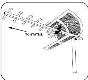
Note: For final installation and connection of your antenna, additional hardware may be required. Before starting assembly, please read through the instructions carefully to determine your specific requirements.
Assembly and installation

natural_image
Mechanical assembly diagram showing a cross-shaped component with dashed arc indicating motion or alignment (no text or symbols)Assembly and installation instructions
Before assembling the antenna, take a moment to familiarize yourself with the antennas' construction. Notice that the boom of the antenna has a top and bottom. The horizontal elements are mounted to the top side of the boom. The reflector on the other hand, does not have a specific top or bottom.
- Extend the folded drive element by carefully folding the "wings" outward so they are at 90 degrees to the boom. (fig.3)

- Attach Transformer to bottom studs of drive elements with wing nuts and washers. (fig.4)
- Slide the reflector screen onto the boom from the rear until the screw holes of the screen bracket line up with the holes on the top and bottom of the boom. Attach the screen to the boom using two (2) 1-1/2" bolts, lockwashers and wing nuts.
Tip:
To make it easier to fit when sliding the screen onto the boom, squeeze the top and bottom of the screen towards each other.
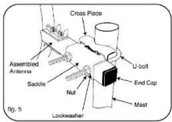
- Insert end caps at end of boom (fig. 5).
- Attach the antenna to the mast: Assemble U-bolt to cross piece. Attach U-bolt assembly loosely to antenna, using saddle, lockwashers and nuts. insert mast through U-bolt. Tighten nuts securely (fig.5) (Mast sold separately).

natural_image
Diagram of two intersecting pipes with a directional arrow indicating movement (no text or symbols)- Connect 2 mast sections as shown in figure 6 (included in SDV9201K only)
Aiming the Antenna
EN
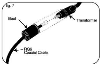
- Connect a good quality RG-6 coaxial cable to the transformer. Slide the weatherproof boot over the connection firmly until it seals (fig.7) (Cable sold separately)

- Attach cable standoff to mast as shown in figure 8 (included in SDV9201K only)
Aiming the Antenna
Before permanently mounting the antenna for digital television (DTV) reception it is a good idea to perform a quick sight survey to find the spot with the best signal. Moving the antenna one way or another just a few feet can make a tremendous difference in the success of the antenna installation.
WARNING - Installation of this product near power lines is dangerous. For your safety, keep ladder and antenna away from power lines. Contact may cause electrocution.
Overview
DTV is a little different than analog TV. With analog TV peak signal strength was the most important factor for good reception and creating a good picture. With DTV peak signal strength is not the most important factor for good reception. This means that our old methods for finding a location and aiming a TV antenna will not give us the best results for DTV. In choosing a permanent location for our DTV antenna we want to look at a couple of mounting locations. There are two methods for testing for the best antenna location:
- Terrestrial Digital receivers internal signal strength indicator.
- Conventional Analog TV pointing method.
Tip:
Do not use a convention signal strength meter for installing a DTV antenna. Chances are this will give you false information and cause the antenna not to work reliably. Severe ghosting is the number one reason for DTV reception problems. Most severe ghosting occurs in locations where there is plenty of signal strength. A conventional signal strength meter will find this location.
DTV Tuner Signal Strength Indicator
If your DTV set top box or DTV tuner in your TV has a signal strength indicator (refer to that components user manual) you can utilize this feature for selecting a location for installation and aiming the antenna.
- Locate antenna in a high location with as few obstructions in front of, behind, or to the sides of the antenna as possible. Optimally the antenna needs to be at least 30 feet above the ground pointed directly in the "line of sight" of the broadcast antenna (Line of sight means that there are not any obstructions between the broadcast and receiving antenna such as buildings, water towers, mountains or trees. Line of sight does not mean you need to be able to see the broadcast antenna with your eye) If you are able to achieve this "line of site installation and do not have severe multi-path problems such as in a very dense high rise area, you will in most cases receive a good stable DTV and Analog TV picture.
- Connect the antenna to your DTV tuner with a good quality transmission line.
- Slowly rotate antenna on mounting mast in both directions until the highest signal strength is achieved on the DTV tuner: Check all DTV channels to make sure the signal is good on all channels you desire to receive from the DTV broadcast tower that you are pointing at. If you have two DTV broadcast towers in two distinct directions and are not able to receive all DTV stations broadcasting in your area install the antenna with a rotor.
- Watch DTV channel for a few minutes to make sure picture is consistently stable without freezing, disappearing or breaking up. If picture is stable, securely mount antenna per enclosed mounting instructions.
- For best results, do not run signal through diplexers or splitters, run new RG6 coaxial cable from antenna location directly to your DTV receiver. If you have a cable run of more than 100 feet or need to run through diplexers and/or splitters use a signal preamplifier that is installed as close to the antenna as possible.
- To avoid signal loss, do not attach the coaxial cable to the mast, use standoffs (fig. 7) (sold separately).
Analog TV Pointing Method
This method uses a conventional analog TV to chose the best spot for a DTV antenna.
- Place antenna in as high location with as few obstructions in front of behind or to the sides of the antenna as possible. Optimally the antenna needs to be 30 feet above the ground pointed directly in the "line of sight" of the broadcast antenna (Line of sight means that there are not any obstructions between the broadcast and receiving antenna such as buildings, water towers, mountains or trees. Line of sight does not mean you need to be able to see the broadcast antenna with your eye) If you are able to achieve this "line of site
DTV Tuner Signal Strength
EN

natural_image
Black and white photo of the Sydney Opera House with visible architectural details, labeled 'Picture With Ghosting' at the bottom (no other text or symbols)

natural_image
Exterior view of the Sydney Opera House with distinctive curved facades, set against a cloudy sky (no signage or text visible)installation and do not have severe multi-path problems such as in a very dense high rise area, you will in most cases receive a good stable DTV and Analog TV picture.
- Tune your analog TV to a UHF TV channel (channel 14 or higher) that is on the same broadcast tower or tower location as the DTV stations you are trying to receive. If you do not know this information you can call your local TV station's engineering department and ask them. If you have internet access, Antennaweb.org is also helpful. (www.antennaweb.org)
- Slowly rotate antenna or walk location area with antenna while monitoring your analog TV. Find the location that has a stable picture with the least amount of ghosting.
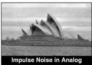
- Very often, ghosting can be minimized if you rotate your antenna until the picture improves. Unfortunately, sometimes there is no solution for the problem due to surrounding terrain/obstructions. We are looking for a picture that is clear and free of ghosting.
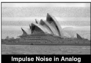
Ghosting - This is a very common problem in areas with large buildings, hills or valleys. The signal bounces off of various surfaces and creates multiple images. This is sometimes called "multi-path" to describe the multiple signals that reach the antenna. In extreme cases, you may see six or more distinct clear images side by side overlapping each other. The problem can usually be resolved by moving the antenna mounting position six feet to the left or right and/or raising your antenna higher to receive a more direct signal.
Do not worry about snow in the analog picture; this is not a problem for DTV. Find a location where the analog TV has the least amount of ghosting, and color in the picture with the audio clearly heard.
- Watch DTV channel for a few minutes to make sure picture is consistently stable without freezing, disappearing or breaking up. If picture is stable, securely mount antenna per enclosed mounting instructions.
- For best results, do not run signal through diplexers or splitters, run new RG6 coaxial cable from antenna location directly to your DTV receiver. If you have a cable run of more than 100 feet or need to run through diplexers and/or splitters use a signal preamplifier that is installed as close to the antenna as possible.
- To avoid signal loss, do not attach the coaxial cable to the mast, use stand offs (fig. 7) (sold separately)
Limited One-Year Warranty
Philips warrants that this product shall be free from defects in material, workmanship and assembly, under normal use, in accordance with the specifications and warnings, for one year from the date of your purchase of this product. This warranty extends only to the original purchaser of the product, and is not transferable. To exercise your rights under this warranty, you must provide proof of purchase in the form of an original sales receipt that shows the product name and the date of purchase. For customer support or to obtain warranty service, please call 919-573-7863. THERE ARE NO OTHER EXPRESS OR IMPLIED WARRANTIES. Philips' liability is limited to repair or, at its sole option, replacement of the product. Incidental, special and consequential damages are disclaimed where permitted by law. This warranty gives you specific legal rights. You may also have other rights that vary from state to state.
Technical Support
Technical Support
For technical support send an email with the model number of the product and a detailed description of your problem to:
Email: accessorysupport@philips.com
©2006
Accessories Service Center
Philips
Accessories and Computer Peripherals,
Ledgewood, NJ 07852 USA
Manufactured in USA
Printed in USA
Contenido
EN
natural_image
Mechanical diagram showing a vertical beam supported by two horizontal supports, with dashed curved arrows indicating motion or force direction (no text or symbols)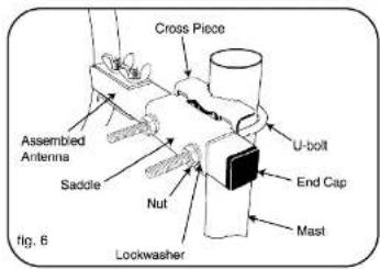

Perspectiva general
natural_image
Black and white photo of the Sydney Opera House with visible stage architecture (no text or symbols on the structure itself)

natural_image
Exterior view of the Sydney Opera House with distinctive curved facades, labeled 'Good Clear Picture' at the bottom (no other text or symbols visible)accessorysupport@philips.com
©2006
Accessories and Computer Peripherals,
L ed g ewood,NJ 07852 USA
Hecho en EE.UU.
Imprimido en EE.UU.

Specifications are subject to change without notice Trademarks are property of Philips Accessories and Computer Peripherals 2006: Philips Accessories and Computer Peripherals, Ledgewood, NJ USA 313520700014 www.philips.com

- PHILIPS
- Safety Instructions
- Antenna Grounding and Safety Warning
- About the Design of Your Antenna
- Assembly and installation
- Assembly and installation instructions
- Tip:
- Aiming the Antenna
- Overview
- DTV Tuner Signal Strength Indicator
- Analog TV Pointing Method
- DTV Tuner Signal Strength
- Limited One-Year Warranty
- Technical Support
- Contenido
- Perspectiva general
Brand : PHILIPS
Model : SDV9201K
Category : TV antenna