
MS1207WA - Barcode Reader MOTOROLA - Free user manual and instructions
Find the device manual for free MS1207WA MOTOROLA in PDF.


| Product Type | Handheld Barcode Scanner |
| Brand | Motorola (by Zebra Technologies) |
| Model | MS1207WA |
| Dimensions (H x W x D) | Approx. 18.6 cm x 7.2 cm x 9.8 cm |
| Weight | Approx. 200 g |
| Power Source | USB bus-powered (5V) or external power supply (optional) |
| Scan Engine | 1D Laser (red LED) |
| Scan Rate | Up to 100 scans per second |
| Readable Codes | UPC/EAN, Code 39, Code 128, Interleaved 2 of 5, and more |
| Interface | USB (keyboard wedge or serial emulation) |
| Operating Temperature | 0°C to 50°C |
| Storage Temperature | -40°C to 70°C |
| Humidity | 5% to 95% non-condensing |
| Drop Spec | 1.5 m drops to concrete |
| Decode Capability | Standard 1D barcodes |
| Cleaning Method | Use a soft, lint-free cloth moistened with water or mild detergent; avoid solvents |
| Included Accessories | USB cable, quick start guide |
| Compatible Systems | Windows, macOS, Linux (via USB) |
Frequently Asked Questions - MS1207WA MOTOROLA
User questions about MS1207WA MOTOROLA
0 question about this device. Answer the ones you know or ask your own.
Ask a new question about this device
Download the instructions for your Barcode Reader in PDF format for free! Find your manual MS1207WA - MOTOROLA and take your electronic device back in hand. On this page are published all the documents necessary for the use of your device. MS1207WA by MOTOROLA.
USER MANUAL MS1207WA MOTOROLA
Symbol MiniScan MSXX07 Series Integration Guide
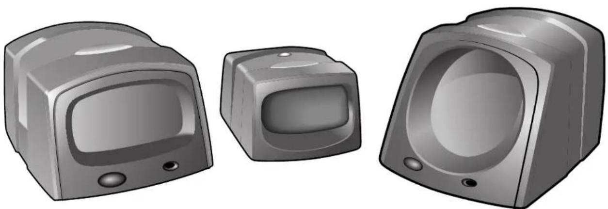
natural_image
Illustration of three vintage-style electronic devices with no visible text or symbolsSymbol MiniScan MSXX07 Series Integration Guide
72E-67135-04
Revision A
May 2008
© 2008 by Motorola, Inc. All rights reserved.
No part of this publication may be reproduced or used in any form, or by any electrical or mechanical means, without permission in writing from Motorola. This includes electronic or mechanical means, such as photocopying, recording, or information storage and retrieval systems. The material in this manual is subject to change without notice.
The software is provided strictly on an “as is” basis. All software, including firmware, furnished to the user is on a licensed basis. Motorola grants to the user a non-transferable and non-exclusive license to use each software or firmware program delivered hereunder (licensed program). Except as noted below, such license may not be assigned, sublicensed, or otherwise transferred by the user without prior written consent of Motorola. No right to copy a licensed program in whole or in part is granted, except as permitted under copyright law. The user shall not modify, merge, or incorporate any form or portion of a licensed program with other program material, create a derivative work from a licensed program, or use a licensed program in a network without written permission from Motorola. The user agrees to maintain Motorola’s copyright notice on the licensed programs delivered hereunder, and to include the same on any authorized copies it makes, in whole or in part. The user agrees not to decompile, disassemble, decode, or reverse engineer any licensed program delivered to the user or any portion thereof.
Motorola reserves the right to make changes to any software or product to improve reliability, function, or design.
Motorola does not assume any product liability arising out of, or in connection with, the application or use of any product, circuit, or application described herein.
No license is granted, either expressly or by implication, estoppel, or otherwise under any Motorola, Inc., intellectual property rights. An implied license only exists for equipment, circuits, and subsystems contained in Motorola products.
MOTOROLA and the Stylized M Logo and Symbol and the Symbol logo are registered in the US Patent & Trademark Office. Bluetooth is a registered trademark of Bluetooth SIG. Microsoft, Windows and ActiveSync are either registered trademarks or trademarks of Microsoft Corporation. All other product or service names are the property of their respective owners.
Motorola, Inc.
One Motorola Plaza
Holtsville, New York 11742-1300
http://www.symbol.com
Patents
This product is covered by one or more of the patents listed on the website: http://www.symbol.com/patents.
Warranty
For the complete Motorola hardware product warranty statement, go to: http://www.symbol.com/warranty.
Revision History
Changes to the original manual are listed below:
| Change Date Description | ||
| -01 Rev A 2/ | 2004 Initial | release. |
| -02 Rev A 6/ | 2004 Added | Embedded Application information. |
| -03 Rev A | 3/2007 | Updated service information and specifications; change RSS code type references to GS1 DataBar |
| -04 Rev A 5/ | 2008 Updated | connected connection drawing, added connecting via USB information, updated operating temperature for MS2207 and MS2207VHD, removed Host Trigger option, removed parameter numbers/hex values, added new UPC/EAN supplemental options and Bookland ISBN format option, updated parameter defaults, updated troubleshooting. |
iv Symbol MiniScan MSXX07 Series Integration Guide
Table of Contents
About This Guide
Introduction...... xiii
Chapter Descriptions ....xiii
Notational Conventions...... xiv
Related Documents ...... xv
Service Information.... xv
Chapter 1: Getting Started
Introduction 1-1
Symbol MSXX07 Series Features 1-2
Typical Applications 1-2
Block Diagram 1-3
Miniscan Block Diagram Descriptions 1-3
Chapter 2: Installation
Introduction 2-1
Unpacking 2-1
Mounting 2-1
Symbol MS1207FZY/MS1207WA/MS2207/MS2207VHD Mounting Dimensions ... 2-2
Symbol MS3207 Mounting Dimensions 2-2
Mounting the Scanner on the Optional Stand 2-3
Mounting the Scanner on the Optional Mounting Bracket 2-4
Connecting the MiniScan 2-6
Connecting the Symbol MSXX07 via USB 2-7
Location and Positioning 2-7
Using the MiniScan as an Embedded Scanner 2-7
Conveyor Applications 2-10
Embedded Applications Requiring a Window 2-12
Accessories 2-15
Application Notes 2-16
TTL RS-232 2-16
USB Warning - Potential Host Side Issues 2-16
Chapter 3: Scanning
Introduction 3-1
MiniScan Scan Patterns 3-1
Symbol MS1207FZY and MS1207WA Scan Pattern 3-1
Symbol MS2207 and MS2207VHD Scan Patterns 3-2
Symbol MS3207 Scan Patterns 3-3
Scan Angle Selection 3-4
Operation in Blink Mode 3-4
Scanning Tips 3-5
Scan the Entire Symbol 3-5
Position at an Angle 3-5
Trigger Options 3-5
Continuous (Default) 3-5
Level Trigger 3-6
Pulse Trigger 3-6
Blink 3-6
Beeper and LED Definitions 3-7
Chapter 4: Symbol MS1207FZY Specifications
Introduction 4-1
Symbol MS1207FZY Electrical Interface 4-2
Symbol MS1207FZY Mechanical Drawings 4-3
Symbol MS1207FZY Technical Specifications 4-5
Symbol MS1207FZY Decode Zone 4-7
Usable Scan Length 4-8
Chapter 5: Symbol MS1207WA Specifications
Introduction 5-1
Symbol MS1207WA Electrical Interface 5-2
Symbol MS1207WA Mechanical Drawings 5-3
Symbol MS1207WA Technical Specifications 5-5
Symbol MS1207WA Decode Zone 5-7
Usable Scan Length 5-8
Chapter 6: Symbol MS2207 Specifications
Introduction 6-1
Symbol MS2207 Electrical Interface 6-2
Symbol MS2207 Mechanical Drawings 6-3
Symbol MS2207 Technical Specifications 6-5
Symbol MS2207 Decode Zones 6-8
Symbol MS2207 1D Decode Zone 6-8
Symbol MS2207 1D Decode Distances 6-9
Symbol MS2207 2D Decode Zone 6-10
Symbol MS2207 2D Decode Distances 6-11
Usable Scan Length 6-11
Chapter 7: Symbol MS2207VHD Specifications
Introduction 7-1
Symbol MS2207VHD Electrical Interface 7-2
Symbol MS2207VHD Mechanical Drawings 7-3
Symbol MS2207VHD Technical Specifications 7-5
Symbol MS2207VHD Decode Zones 7-8
Symbol MS2207VHD 1D Decode Zone 7-8
Symbol MS2207VHD 1D Decode Distances 7-9
Symbol MS2207VHD 2D Decode Zone 7-10
Symbol MS2207VHD 2D Decode Distances 7-11
Usable Scan Length 7-11
Chapter 8: Symbol MS3207 Specifications
Introduction 8-1
Symbol MS3207 Electrical Interface 8-2
Symbol MS3207 Mechanical Drawings 8-4
Symbol MS3207 Technical Specifications 8-6
Symbol MS3207 Decode Zones 8-9
Symbol MS3207 Omnidirectional Decode Distances 8-9
Symbol MS3207 2D Slab/Raster Decode Distances 8-11
Usable Scan Length 8-12
Chapter 9: Maintenance and Troubleshooting
Introduction 9-1
Maintenance 9-1
Troubleshooting 9-2
Chapter 10: Parameter Menus
Introduction 10-1
Operational Parameters 10-1
Default Table 10-2
Set Default Parameter 10-7
Scanning Options 10-8
Beeper Volume 10-8
Beeper Tone 10-9
Beeper Frequency Adjustment 10-9
Laser On Time 10-10
Scan Angle 10-10
Power Mode 10-11
Trigger Mode 10-11
Scanning Mode 10-12
Aiming Mode 10-13
Programmable Raster Height and Raster Expansion Speed 10-14
Timeout Between Decodes 10-15
Beep After Good Decode 10-16
Transmit "No Read" Message 10-16
Parameter Scanning 10-17
Linear Code Type Security Level 10-18
Bi-directional Redundancy 10-19
UPC/EAN 10-20
Enable/Disable UPC-A 10-20
Enable/Disable UPC-E 10-20
Decode UPC/EAN Supplementals 10-24
User-Programmable Supplementals 10-28
Decode UPC/EAN Supplemental Redundancy 10-28
Transmit UPC-A Check Digit 10-29
Transmit UPC-E Check Digit 10-29
Transmit UPC-E1 Check Digit 10-30
UPC-A Preamble 10-31
UPC-E Preamble 10-32
Linear UPC/EAN Decode 10-38
UPC Half Block Stitching 10-38
Code 128 10-39
Enable/Disable Code 128 10-39
Enable/Disable UCC/EAN-128 10-39
Enable/Disable ISBT 128 10-40
Lengths for Code 128 10-40
Code 128 Decode Performance 10-41
Code 128 Decode Performance Level 10-42
Code 39 10-43
Enable/Disable Code 39 10-43
Enable/Disable Trioptic Code 39 10-43
Convert Code 39 to Code 32 10-44
Code 32 Prefix 10-44
Set Lengths for Code 39 10-45
Code 39 Check Digit Verification .... 10-46
Transmit Code 39 Check Digit 10-46
Enable/Disable Code 39 Full ASCII 10-47
Code 39 Decode Performance 10-48
Code 39 Decode Performance Level 10-49
Code 93 10-50
Enable/Disable Code 93 10-50
Set Lengths for Code 93 10-51
Code 11 10-52
Enable/Disable Code 11 10-52
Set Lengths for Code 11 10-53
Code 11 Check Digit Verification .... 10-54
Transmit Code 11 Check Digit 10-55
Interleaved 2 of 5 10-56
Enable/Disable Interleaved 2 of 5 10-56
Set Lengths for Interleaved 2 of 5 10-57
I 2 of 5 Check Digit Verification .... 10-58
Transmit I 2 of 5 Check Digit 10-59
Convert | 2 of 5 to EAN-13 10-59
Discrete 2 of 5 10-60
Enable/Disable Discrete 2 of 5 10-60
Set Lengths for Discrete 2 of 5 10-61
Codabar 10-62
Enable/Disable Codabar 10-62
Set Lengths for Codabar 10-63
CLSI Editing 10-64
NOTIS Editing 10-64
MSI Plessey 10-65
Enable/Disable MSI Plessey 10-65
Set Lengths for MSI Plessey 10-66
MSI Plessey Check Digits 10-67
Transmit MSI Plessey Check Digit 10-67
MSI Plessey Check Digit Algorithm 10-68
PDF417/MicroPDF417 10-69
Enable/Disable PDF417 10-69
Enable/Disable MicroPDF417 10-69
MicroPDF Performance 10-70
Code 128 Emulation 10-71
GS1 DataBar 10-72
GS1 DataBar-14 10-72
GS1 DataBar Limited 10-72
GS1 DataBar Expanded 10-73
Convert GS1 DataBar to UPC/EAN 10-73
Composite 10-74
Composite CC-C 10-74
Composite CC-A/B 10-74
Composite TLC-39 10-75
UPC Composite Mode 10-76
Data Options 10-77
Transmit Code ID Character 10-77
Prefix/Suffix Values 10-79
Scan Data Transmission Format 10-80
Event Reporting 10-82
Decode Event 10-83
Boot Up Event 10-83
Parameter Event 10-84
Macro PDF Features 10-85
Transmit Symbols in Codeword Format 10-85
Transmit Unknown Codewords 10-86
Escape Characters 10-86
Delete Character Set ECIs 10-87
ECI Decoder 10-87
Transmit Macro PDF User-Selected Fields 10-88
Transmit File Name 10-88
Transmit Block Count 10-89
Transmit Time Stamp 10-89
Chapter 11: RS-232 Interface
Introduction 11-1
RS-232 Default Parameters 11-2
RS-232 Host Parameters 11-3
RS-232 Host Types 11-5
Baud Rate 11-7
Parity 11-8
Stop Bit Select 11-9
Data Bits 11-9
Check Receive Errors 11-10
Hardware Handshaking 11-10
Software Handshaking 11-12
Host Serial Response Time-out 11-14
RTS Line State 11-15
Beep on
Intercharacter Delay 11-16
Nixdorf Beep/LED Options 11-17
Ignore Unknown Characters 11-17
Chapter 12: USB Interface
Introduction 12-1
Connecting a USB Interface 12-1
USB Default Parameters 12-2
USB Host Parameters 12-3
USB Device Type 12-3
USB Country Keyboard Types (Country Codes) 12-4
USB Keystroke Delay 12-7
USB CAPS Lock Override 12-8
USB Ignore Unknown Characters 12-9
Emulate Keypad 12-9
USB Keyboard FN 1 Substitution 12-10
Function Key Mapping 12-10
Simulated Caps Lock 12-11
Convert Case 12-11
Chapter 13: Advanced Data Formatting
Introduction 13-1
Rules: Criteria Linked to Actions 13-1
Using ADF Bar Codes 13-2
ADF Bar Code Menu Example 13-2
Rule 1: The Code 128 Scanning Rule 13-3
Rule 2: The UPC Scanning Rule 13-3
Alternate Rule Sets 13-3
Rules Hierarchy (in Bar Codes) 13-4
Default Rules 13-5
ADF Bar Codes 13-6
Special Commands 13-8
Pause Duration 13-8
Begin New Rule 13-8
Save Rule 13-8
Erase 13-9
Quit Entering Rules 13-9
Disable Rule Set 13-10
Criteria 13-11
Code Types 13-11
Code Lengths 13-16
Message Containing A Specific Data String 13-20
Actions 13-25
Send Data 13-25
Setup Field(s) 13-28
Modify Data 13-33
Pad Data with Spaces 13-35
Pad Data with Zeros 13-39
Beeps 13-44
Send Keystroke (Control Characters and Keyboard Characters) 13-44
Send Right Control Key 13-80
Send Graphic User Interface (GUI) Characters 13-81
Turn On/Off Rule Sets 13-86
Alphanumeric Keyboard 13-88
Chapter 14: Mounting Template
Introduction 14-1
Symbol MS1207FZY/MS1207WA/MS2207/MS2207VHD Mounting Template ..... 14-1
Symbol MS3207 Mounting Template 14-2
Appendix A: ASCII Character Sets
RS-232 ASCII Character Set ...... A-1
USB ASCII Character Set A-6
Index
Tell Us What You Think...
xii Symbol MiniScan MSXX07 Series Integration Guide
About This Guide
Introduction
The Symbol MiniScan MSXX07 Series Integration Guide provides general instructions for mounting, setting up, and programming the following MiniScan models:
- MS1207FZY
- MS1207WA
- MS2207
- MS2207VHD
- MS3207.

NOTE It is recommended that an opto-mechanical engineer perform an opto-mechanical analysis prior to integration.
Chapter Descriptions
Topics covered in this guide are as follows:
- Chapter 1, Getting Started provides an overview of the MiniScan scanners and features, and provides a block diagram of the scanner.
• Chapter 2, Installation describes how to mount and install the MiniScan scanner. - Chapter 3, Scanning provides information on scan patterns, scanning, triggering options, and beeper and LED definitions.
- Chapter 4, Symbol MS1207FZY Specifications provides the technical and scanning specifications for the Symbol MS1207FZY scanner.
- Chapter 5, Symbol MS1207WA Specifications provides the technical and scanning specifications for the Symbol MS1207WA scanner.
-
Chapter 6, Symbol MS2207 Specifications provides the technical and scanning specifications for the Symbol MS2207 scanner.
-
Chapter 7, Symbol MS2207VHD Specifications provides the technical and scanning specifications for the Symbol MS2207VHD scanner.
- Chapter 8, Symbol MS3207 Specifications provides the technical and scanning specifications for the Symbol MS3207 scanner.
- Chapter 9, Maintenance and Troubleshooting provides information on maintaining and troubleshooting the MiniScan scanners.
- Chapter 10, Parameter Menus describes the programmable parameters and provides bar codes for programming.
• Chapter 11, RS-232 Interface describes how to set up the scanner for RS-232 operation.
• Chapter 12, USB Interface describes how to set up the scanner for USB operation. - Chapter 13, Advanced Data Formatting (ADF) describes how to customize scanned data before transmitting to the host.
• Chapter 14, Mounting Template provides mounting templates for the MiniScan scanners. - Appendix A, ASCII Character Sets provides prefix and suffix values to assign for ASCII character data transmission.
Notational Conventions
The following conventions are used in this document:
- Italics are used to highlight chapters and sections in this and related documents.
- bullets (•) indicate:
- Action items
- Lists of alternatives
- Lists of required steps that are not necessarily sequential
- Sequential lists (e.g., those that describe step-by-step procedures) appear as numbered lists.

NOTE This symbol indicates something of special interest or importance to the reader. Failure to read the note will not result in physical harm to the reader, equipment or data.

CAUTION This symbol indicates that if this information is ignored, the possibility of data or material damage may occur.

WARNING! This symbol indicates that if this information is ignored the possibility that serious personal injury may occur.
Related Documents
The following document provides more information for MiniScan Series scanners.
• MiniScan Family of Scanners Quick Reference Guide, p/n 72-58809-xx
For the latest version of this guide and all guides, go to: http://www.symbol.com/manuals.
Service Information
If you have a problem with your equipment, contact Motorola Enterprise Mobility Support for your region. Contact information is available at: http://www.symbol.com/contactsupport.
When contacting Enterprise Mobility Support, please have the following information available:
- Serial number of the unit
• Model number or product name - Software type and version number.
Motorola responds to calls by E-mail, telephone or fax within the time limits set forth in support agreements.
If your problem cannot be solved by Motorola Enterprise Mobility Support, you may need to return your equipment for servicing and will be given specific directions. Motorola is not responsible for any damages incurred during shipment if the approved shipping container is not used. Shipping the units improperly can possibly void the warranty.
If you purchased your Enterprise Mobility business product from a Motorola business partner, contact that business partner for support.
xvi Symbol MiniScan MSXX07 Series Integration Guide
Chapter 1 Getting Started

CAUTION Use of controls, adjustments or procedures other than those specified here can result in hazardous laser light exposure.
Introduction
The MiniScan family of industrial fixed-mount scanners is specifically designed for stand-alone applications, and OEM applications such as kiosks.

natural_image
Illustration of three vintage-style electronic devices with no visible text or symbolsFigure 1-1 MiniScan Family of Scanners
Symbol MSXX07 Series scanners provide easy and flexible integration of bar code scanning into a host device, and include the following models:
- The Symbol MS1207FZY offers fuzzy logic for premium scanning performance on all types of 1D bar codes including poorly printed and low contrast symbols. The MS1207FZY features a compact design for superior performance and durability in a form factor that easily integrates into OEM devices for embedded applications such as medical instruments, diagnostic equipment, vending machines, and gaming. As a fixed-mount scanner, the MS1207FZY is ideal for applications requiring unattended scanning such as manufacturing, warehouse and shipping, conveyor belts, library and document tracking systems.
-
The Symbol MS1207WA Wide Angle Scanner features a broad 60° scan angle to accommodate large 1D bar codes within extremely close range. This scanner is ideal for high-volume, near-contact scanning applications such as kiosks, ATMs, assembly lines, warehouse and shipping.
-
The Symbol MS2207 and MS2207VHD offer a "smart" raster pattern optimized for 2D applications and poorly printed 1D bar codes. The high scan rate ensures fast and reliable data on all 1D symbols, and 2D codes such as PDF417, MicroPDF, GS1 DataBar and composite codes. These scanners are perfect for automated data entry applications that require high-speed scanning, performance, and small size, such as conveyor belts, manufacturing and warehouse, gas pumps, and security/ID verification.
- The Symbol MS3207 features a high-speed omnidirectional scan pattern that makes it easy and intuitive for consumers to scan bar codes at the point of activity. The omnidirectional scan pattern reads bar codes quickly and accurately, minimizing the need for precise positioning of linear 1D bar codes. The MS3207 provides an easy and cost-effective way to enhance existing OEM devices with high-performance 1D and 2D scanning, making it the ideal solution for applications that require fast, accurate scanning such as kiosks, ATMs, listening stations, lottery machines, and vending machines.
Symbol MSXX07 Series Features
- Stand-alone or OEM applications
- Quick and easy integration for OEM devices
- Excellent scanning performance on all types of bar codes (MS1207FZY and MS1207WA support 1D bar codes only)
• Rugged IP54 sealed housing with integrated beeper
• Multi-interface (USB, Synapse, TTL RS-232) - Easy programming and configuration
• Flexible mounting options
• LEDs and an integrated beeper indicating scanner power status and successful decodes.
Typical Applications
MiniScan is the perfect solution for the following applications:
Fixed Mount Standalone Applications
• Manufacturing / warehouse
- Conveyer belts
• Security / ID verification
- POS
- Library tracking
- Document control.
OEM Applications
- Kiosks / ATMs
• Music listening stations
• Security / ID verification
• Lottery terminals / gaming.
Block Diagram
The MiniScan block diagram illustrates the functional relationship of the MiniScan components. Following is a detailed description of each component in the block diagram.

flowchart
graph TD
    A["DB9"] -->|flex-flow| B["Interface Board"]
    B --> C["Interface"]
    C --> D["Decoded Scan Engine"]
    B --> E["Beeper"]
    B --> F["External Beeper"]
    B --> G["Interface Circuit TTL-RS232, Synapse, USB"]
    B --> H["Red/Green LED"]
    B --> I["External Trigger"]
    C --> J["Interface"]
    J --> K["Interface Board"]
Figure 1-2 MiniScan Block Diagram
Miniscan Block Diagram Descriptions
Decoded Scan Engine - The scan engine emits a beam of laser light that reflects off the bar code. Black bars absorb light, white spaces reflect light. The scan engine collects the reflected light and processes the signal through several analog filters. The filtered signal is digitized into a Digitized Barcode Pattern (DBP). The decoder micro-controller analyzes timing information to decode and transmit the data contained in the bar code.
Interface Board - The interface board adapts the scan engine's interface into usable signals and data for the intended host. It also contains a beeper and red/green LED for audio/visual feedback, and provides for an external trigger and external beeper.
The interface board converts the scan engine's data to Synapse, USB, or TTL level RS-232. A separate host adapter cable (p/n 25-62186-xx) converts the TTL level RS-232 output to standard RS-232 levels. All interface types are auto-detected based on the host cable attached.
DB9 - The DB9 connector provides a sealed outlet for the various interface signals used between a MiniScan scanner and the host. It also maintains pin compatibility with the previous generation LS1220 MiniScan host cables.
Chapter 2 Installation
Introduction
This chapter provides information on unpacking, mounting, and installing the MiniScan.
Unpacking
Remove the MiniScan from its packing and inspect for damage. If the scanner is damaged, contact Motorola Enterprise Mobility Support. See page xv for contact information.
KEEP THE PACKING. It is the approved shipping container and should be used if the equipment needs to be returned for servicing.
Mounting
There are three mounting holes (threaded inserts) on the bottom of the chassis.
The following figures provide mounting dimensions for the MiniScan scanner housings. For a mounting template, see Mounting Template on page 14-1.

NOTE Use only non-magnetic M3x.5 screws with a maximum length of 3.6M to mount the MiniScan scanner chassis.
Symbol MS1207FZY/MS1207WA/MS2207/MS2207VHD Mounting Dimensions
![1.12 [28] Threaded Inserts Note: Dimensions are in inches [mm]. 1.50 [38]](/content/2026/05/1068115/images/ffeda3d0bb2bade3610bc8aa27370f0233ea5da169dd46cc663d8d96d0fce54c.jpg)
Figure 2-1 Symbol MS1207FZY/MS1207WA/MS2207/MS2207VHD Mounting Dimensions
Symbol MS3207 Mounting Dimensions
![1.82 [46] Threaded Inserts Note: Dimensions are in inches [mm]. 1.50 [38]](/content/2026/05/1068115/images/d5ff92e8c950f4ca949508f4e8727ccfb0fbad8da9878e0ddebabf8d9ac61a4b.jpg)
Figure 2-2 Symbol MS3207 Mounting Dimensions
Mounting the Scanner on the Optional Stand
To mount the scanner on the optional stand:
-
Place the bottom of the scanner on the stand's scanner mount, aligning the scanner's center threaded insert (beneath the scan window) with the center mounting hole on the front of the stand. The two rear threaded inserts on the bottom of the scanner align with the proper mounting holes on the stand.
-
Secure the scanner to the stand using the three screws provided with the stand.
Assembling the Stand

-
Unscrew the wingnut from the bottom of the one-piece scanner mount.
-
Fit the bottom of the neck piece into the opening on the top of the stand base.
-
Tighten the wingnut underneath the base to secure the cup and neck piece (see the note below).
-
Bend the neck to the desired position for scanning.
Figure 2-3 Assembling the Stand

NOTE Before tightening the wingnut under the base, ensure that the flat areas on the flexible neck fit securely in the grooves in the base.
Mounting the Stand (optional)
You can attach the base of the scanner's stand to a flat surface using two screws or double-sided tape (not provided).
Screw Mount
-
Position the assembled base on a flat surface.
-
Screw one #10 wood screw into each screw-mount hole until the base of the stand is secure.
Tape Mount
- Peel the paper liner off one side of each piece of tape and place the sticky surface over each of the three rectangular tape areas.
- Peel the paper liner off the exposed sides of each piece of tape and press the stand on a flat surface until it is secure.

Figure 2-4 Mounting the Stand
Mounting the Scanner on the Optional Mounting Bracket
The optional mounting bracket kit consists of a scanner bracket, a mounting bracket, and the hardware required to mount the scanner. The bracket kit accommodates adjustable angles for optimal positioning of the scanner.
To mount the MiniScan scanner on the bracket, first secure the scanner to the scanner bracket, then attach the mounting bracket to the wall (see Figure 2-5 on page 2-5):
- Tilt the scanner bracket forward to access the center scanner mounting hole on the bracket.
- Place the bottom of the scanner on the scanner bracket, aligning the scanner's center threaded insert (beneath the scan window) with the center mounting hole on the scanner bracket.
- Insert one of the screws provided through the mounting hole and into the scanner's center threaded insert.
For the Symbol MS1207FZY, MS1207WA, MS2207, and MS2207VHD, use a #0 Phillips screwdriver; for the Symbol MS3207, use a #1 Phillips screwdriver.
- Tilt the scanner bracket in the opposite direction to access the rear scanner mounting holes (which are aligned with the rear inserts on the bottom of the scanner), then insert the remaining two screws provided through the two rear mounting holes and into the scanner's threaded inserts.
- Secure the mounting bracket to a flat surface by inserting 1/8" or smaller fasteners through the surface and into the bracket's mounting holes. There are four mounting holes on the bottom of the mounting bracket for horizontal mounting, and six holes on the side for vertical mounting.
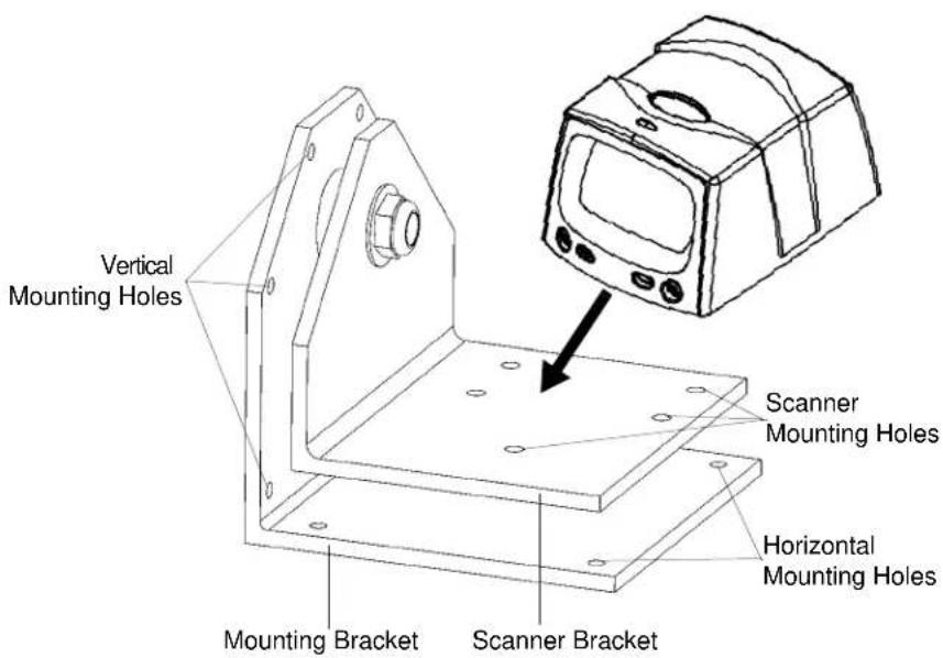
Figure 2-5 Mounting the Scanner and Bracket
Connecting the MiniScan
To connect the MiniScan to the host, connect the scanner cables in the order shown in Figure 2-6.

Figure 2-6 Typical Connection Diagram
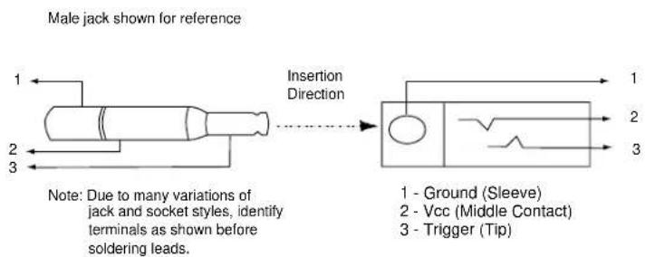
flowchart
graph LR
    A["1 - Ground (Sleeve)"] --> B["2 - Vcc (Middle Contact)"]
    B --> C["3 - Trigger (Tip)"]
    D["Note: Due to many variations of jack and socket styles, identify terminals as shown before soldering leads."] --> E["Insertion Direction"]
Figure 2-7 Trigger Jack Connector Pins
Connecting the Symbol MSXX07 via USB
Using a PC running Microsoft Windows:
- Connect the USB cable to the USB port on the host.
- Connect the other end of the USB cable to the scanner as indicated on the cable. The scanner powers up and beeps.
- On the host, open a word processing program such as Microsoft Word.
- Present a bar code to the scanner. A beep indicates a decode, and the data appears on the host screen.
Location and Positioning

CAUTION
The location and positioning guidelines provided do not consider unique application characteristics. Motorola recommends that an opto-mechanical engineer perform an opto-mechanical analysis prior to integration.

NOTE Integrate the scanner in an environment no more extreme than the product's specification, where the scanner will not exceed its temperature range. For instance, do not mount the scanner onto or next to a large heat source. When placing the scanner with another device, ensure there is proper convection or venting for heat. Follow these suggestions to ensure product longevity, warranty, and overall satisfaction with the scanner.
Using the MiniScan as an Embedded Scanner
You can mount the MiniScan read symbols that are automatically presented, or that are presented in a pre-determined location. In these applications, MinScan positioning with respect to the symbol is critical. Failure to properly position the MiniScan can result in unsatisfactory scanning performance. A thermal analysis is also recommended.
Two methods of positioning the scanner are provided:
- Use the Calculating the Usable Scan Length Method on page 2-8 with consistently good quality symbols. This provides a mathematical solution to find the usable scan length.
- The Testing the Usable Scan Length Method on page 2-9 uses real situation testing to adjust the usable scan length to fit the application conditions.
Calculating the Usable Scan Length Method
Calculate usable scan length as follows (see Figure 2-8 on page 2-8):
L = 1. 8 × (D + d + B) × Tan (A / 2)
Table 2-1 Calculation Constants
| Constants B A | ||
| MS1207FZY (Default Mode) 1.17 42° | ||
| MS1207FZY (Alternate Mode) 1.17 30° | ||
| MS1207WA 1.17 60° | ||
| MS2207 1.53 34° | ||
| MS2207VHD 1.53 34° | ||
| MS3207 1.93 34° |
where:
D = Distance (in inches) from the front edge of the host housing to the bar code.
d = The host housing's internal optical path from the edge of the housing to the front of the MiniScan scanner.
B = Internal optical path from the scan mirror to the front edge of the MiniScan scanner.
A = Scan angle in degrees.

NOTE Usable scan length determined by this formula, or 90% of scan line at any working distance. This formula is based on good quality symbols in the center of the working range and length of bar code.

flowchart
graph TD
    A["MiniScan"] --> B["Host System"]
    B --> C["Bar Code"]
    C --> D["1/2 L"]
    C --> E["L"]
    C --> F["1/2 L"]
    style A fill:#f9f,stroke:#333
    style B fill:#ccf,stroke:#333
    style C fill:#cfc,stroke:#333
    style D fill:#fcc,stroke:#333
    style E fill:#cff,stroke:#333
    style F fill:#ffc,stroke:#333
Figure 2-8 Usable Scan Length Diagram
Testing the Usable Scan Length Method
Due to the variety of symbol sizes, densities, print quality, etc., there is no simple way to calculate the ideal symbol distance. To optimize performance, use the Testing The Usable Scan Length positioning method:
- Measure the maximum and minimum distances at which the symbols can be read.
- Check the near and far range on several symbols. If they are not reasonably consistent there may be a printing quality problem that can degrade the performance of the system. Motorola can provide advice on how to improve the installation.

NOTE Poor quality symbols (from bad printing, wear, or damage) may not decode well when placed in the center of the depth of field (especially higher density codes). The scan beam has a minimum width in the central area, and when the scanner tries to read all symbol imperfections in this area it may not decode. After a preliminary spot is determined using good quality symbols, test several reduced quality symbols and adjust the spot for the best overall symbol position.
-
Locate the scanner so the symbol is near the middle of the near/far range.
-
Center the symbol (left to right) in the scan line whenever possible.
-
Position the symbol so that the scan line is as near as possible to perpendicular to the bars and spaces in the symbol.
-
Avoid specular reflection (glare) off the symbol by tilting the top or bottom of the symbol away from the scanner. The exact angle is not critical, but it must be large enough so that if a mirror were inserted in the symbol location, the reflected scan line would miss the front surface of the scanner. For the maximum allowable angles refer to the Skew, Pitch and Roll angles listed in each MiniScan Technical Specifications table.
-
If placing an additional window between the scanner and the symbol, determine the optimum symbol location using a representative window in the desired window position.
-
Give the scanner time to dwell on the symbol for several scans. When first enabled, the MiniScan may take two or three scans before it reaches maximum performance. Enable the MiniScan before presenting the symbol, if possible.
Conveyor Applications
Conveyor applications require setting the conveyor velocity to optimize the scanner's ability to read symbols. Also consider the orientation of the symbol with respect to the conveyor direction. Figure 2-9 on page 2-10 illustrates the relationship of the conveyor velocity with respect to a symbol positioned perpendicular to the conveyor direction and Figure 2-10 on page 2-11 illustrates the relationship of the conveyor velocity with respect to a symbol positioned parallel to the conveyor direction.
Symbol is Perpendicular to Conveyor Movement
With the symbol bars perpendicular to the conveyor belt direction (Picket Fence presentation) the relationship is:
V = (R × (F - W)) / N
where:
V = Velocity of the conveyor (inches/second)
R = Scan Rate (see technical specifications)
F = 80% of width of scan beam
W = Symbol Width (inches)
N = Number of scans over symbol (minimum of 10 scans)
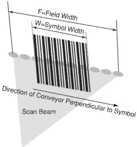
Figure 2-9 Symbol Perpendicular To Conveyor Movement
Example
R = 640 scans per second
F = 80% of 6 in.
W = 4 in.
N = 10
V = (640 × ((0.8 × 6) - 4))) / 10 = 51.2 in./sec
Symbol is Parallel to Conveyor Movement
With the symbol bars parallel to the conveyor belt direction (ladder presentation) the relationship is:
V = (R × H) / N
where:
V = Velocity of the conveyor (inches/second)
R = Scan Rate of scanner (see technical specifications)
H = Symbol height
N = Number of scans over symbol (minimum of 10 scans)

Figure 2-10 Symbol Parallel To Conveyor Movement
Example
Use the previous formula to calculate the number of scans for a specific bar code, scanner, and conveyor speed; a minimum of 10 scans per symbol is recommended.
R = 640 scans/sec
H = 60 mil
N = 10 scans
V = (640 × .060) / 10 = 3.84 in./sec
Embedded Applications Requiring a Window
Use the following guidelines for applications that require a window in front of the MiniScan.

NOTE Motorola does not recommend placing an exit window in front of the MiniScan; however, the following information is provided for applications that require such a window.
Window Material
Many window materials that look perfectly clear can contain stresses and distortions that can reduce scanner performance. For this reason, Motorola highly recommends only optical glass or cell-cast acrylic with an anti-reflection coating. Following is a description of acrylic, and CR-39, another popular window material.
Table 2-2 on page 2-13 outlines the suggested window properties.

CAUTION Consult an opto-mechanical engineer to recommend an appropriate window material and to determine if coatings are appropriate for the specific application.

NOTE Do not use polycarbonate material.
Acrylic
When fabricated by cell-casting, acrylic has very good optical quality and low initial cost. However, protect the surface from the environment as acrylic is susceptible to attack by chemicals, mechanical stresses, and UV light. Acrylic has reasonably good impact resistance and can be ultrasonically welded.
CR-39
CR-39 is a thermal-setting plastic produced by the cell-casting process, and is commonly used in plastic eye glasses lenses. CR-39 has excellent chemical and environmental resistance, including good surface hardness. Typically it does not require hard-coating, but can be hard coated for severe environments. CR-39 has reasonably good impact resistance and cannot be ultrasonically welded.
Chemically Tempered Float Glass
Glass is a hard material which provides excellent scratch and abrasion resistance. However, unannealed glass is brittle. Increasing flexibility strength with minimal optical distortion requires chemical tempering. Glass cannot be ultrasonically welded and is difficult to cut into odd shapes.
Table 2-2 Suggested Window Properties
| Property Description | |
| Material Red cell-cast acrylic. | |
| Spectral Transmission 85% minimum from 640 to 690 nanometers. | |
| Thickness 0.059 ± 0.005 | |
| Wavefront Distortion (transmission) 0.2 wavelengths peak-to-valley maximum over any 0.08 in. diameter within the clear aperture. | |
| Clear Aperture To extend to within 0.04 in. of the edges all around. | |
| Surface Quality 60-20 scratch/dig | |
| Coating Both sides to be anti-reflection coated to provide 0.5% max reflectivity(each side) from 640 to 690 nanometers at nominal window tilt angle.Coatings must comply with the hardness adherence requirements of MIL-M-13508. | |
Window Coatings
Table 2-3 on page 2-14 lists some exit window manufacturers and anti-reflection coaters.
Anti-Reflection Coatings
Apply an anti-reflection coating to the inside and/or outside of the window to significantly reduce the amount of light reflected off the window, back into the scan engine. The coating can also improve the range of acceptable window positions and minimize performance degradation due to signal loss as the light passes through the window. Using anti-reflection coatings on both the inside and outside of the window is highly recommended.
Polysiloxane Coating
Polysiloxane type coatings are applied to plastic surfaces to improve the surface resistance to both scratch and abrasion. They are usually applied by dipping, then air-drying in an oven with filtered hot air.
Table 2-3 Window Manufacturers and Coaters
| Company Discipline Specifics | ||
| Evaporated Coatings, Inc.2365 Maryland RoadWillow Grove, PA 19090(215) 659-3080 | Anti-reflection coater Acrylic window | supplierAnti-reflection coater |
| Fosta-Tek Optics, Inc.320 Hamilton StreetLeominster, MA 01453(978) 534-6511 | Cell-caster, hard coater, laser cutter | CR39 exit window manufacturer |
| Glasflex Corporation4 Sterling RoadSterling, NJ 07980(908) 647-4100 | Cell-caster Acrylic exit window manufacturer | |
| Optical Polymers Int. (OPI)110 West Main StreetMilford, CT 06460(203)-882-9093 | CR-39 cell-caster, coater, laser cutter | CR39 exit window manufacturer |
| Polycast70 Carlisle PlaceStamford, CT 06902800-243-9002 | acrylic cell-caster, hard coater,laser cutter | Acrylic exit window manufacturer |
| TSP2009 Glen ParkwayBatavia, OH 45103800-277-9778 | acrylic cell-caster, coater, laser cutter | Acrylic exit window manufacturer |
Embedded Window Angle and Position
If a window is placed between the MiniScan and the item to scan, observe the following guidelines:
- Window Clear Opening - Make the clear opening of the window large enough so that the entire scan beam passes through the window. Cutting off any part of the beam can result in internal reflections and degrade decode range performance. Ensure that window placement relative to the MiniScan accounts for tolerances on all parts involved in that assembly.
- Window Angle - Angle the window at least 20 more than the tilt of the window on the scanner (see Table 2-4). Further tilting the window is acceptable and decreases the possibility of a secondary reflection from that window degrading the scanner's performance.
- Optical Working Range - Adding a window can reduce the working range of the scanner since there is a signal loss when passing through window material. To minimize this reduction, use a special coating described in Window Coatings on page 2-13. To understand the difference, test the scanner in the desired orientation and see if the difference affects scanner performance.
Table 2-4 Secondary Window Angles
| MiniScan Model | MiniScan Exit Window Angle from Vertical | Minimum Secondary Window Angle from Vertical |
| MS1207FZY, MS2207, MS2207VHD, MS2207WA | 30irc | 32irc |
| MS3207 | 35irc | 37irc |
Accessories
The following accessories are available for the MiniScan scanner, and can be found in Symbol's Solution Builder (ordering guide).
- For power connection
- 110V power supply kit, US, p/n KT-14001-001R (replaces p/n 50-14000-008/008R)
• 220V power supply, Europe, p/n 50-14000-009
• 100V power supply, Asia, p/n 50-14000-010
• 264V Universal power supply (also order cables below), p/n 50-14001-001
- DC line cord (power supply to scanner), p/n 50-16002-009
• AC line cord (wall outlet to power supply), p/n 23844-00-00
- RS-232
- TTL RS-232 to True RS-232 conversion cable, p/n 25-62186-XX
- Female DB9 with straight connector to RS-232 host (female DB9), with trigger jack and no beeper, p/n 25-13227-XX
- Female DB9 with straight connector to RS-232 host (female DB9), with trigger jack and beeper, p/n 25-13228-XX
• Female DB9 with straight connector to RS-232 host (female DB9), p/n 25-58918-XX
• Female DB9 with right angle connector to RS-232 host (female DB9), p/n 25-58919-XX - Female DB9 with straight connector to RS-232 host (female DB9), with trigger jack and no hardware handshaking, p/n 25-63736-XX
- USB
- Female DB9 with straight connector with trigger jack and beeper to USB (Type A connector), p/n 25-58925-XX
• Female DB9 with right angle connector to USB host (Type A connector), p/n 25-58923-XX
• Female DB9 straight to USB, p/n 25-58926-XX
- Synapse Adapter
• Female DB9 with straight connector to Synapse Adapter Cable (6 ft. straight), p/n 25-58921-XX
- Cable Adapters
• Female 25 pin D, TxD on pin 2, p/n 50-12100-378
• Female 25 pin D, TxD on pin 3, p/n 50-12100-377
• Male 25 pin D, TxD on pin 2, p/n 50-12100-380
• Male 25 pin D, TxD on pin 3, p/n 50-12100-379
- Optional Accessories
- Push button trigger cable, p/n 25-04950-01R
• Photo sensor trigger cable, p/n 25-13176-01R (retroreflective, IR 850 nm, 7 foot range)
• Fixed-mount stand, p/n 20-60136-01R - Mounting bracket, p/n KT-65578-01R
Application Notes
TTL RS-232
Standard RS-232 voltage levels typically range between +12V and -12V to ensure adequate noise rejection over long distances. Devices which support TTL level RS-232 signaling typically drive signals between 0V and +5V. Extensive testing has shown that TTL levels are interpreted correctly by the majority of standard RS-232 hosts over cable distances of six feet or less, even in extreme conditions.
Multi-interface Miniscan products fall into the TTL RS-232 device category. All standard RS-232 cables available from Motorola for the Miniscan family measure six feet or less, and should not present a problem. If a particular host does not support TTL levels, a separate conversion cable is available (25-62186-xx) which contains electronics to adapt the TTL levels of a multi-interface Miniscan into standard RS-232 levels.
USB Warning - Potential Host Side Issues
The Universal Serial Bus provides a smart plug-and-play interface for easy integration. In USB communication, the root hub located on the host controls all traffic. USB hosts in general react poorly in certain harsh environments compared to traditional host interfaces such as RS-232. These environments include areas with high ESD levels or situations in which the system is subject to Electrical Fast Transients (EFT).
Typical symptoms of these environments are:
- Frequent scanner resets
- Scanner occasionally loses power (due to host initiated shutdown)
• Occasional host lockups.
Because multi-interface Miniscan products are often exposed to these environments due to the nature of scanner placement, they have been safeguarded as much as possible to prevent physical damage. Despite design precautions, testing shows that some USB hosts cannot tolerate these environments. In this case, try placing a self-powered USB hub close to the host, between the scanner and host, as a buffer to the host against the harsh environment. This may not be a valid solution in all cases.
Chapter 3 Scanning
Introduction
This chapter provides information on scan patterns, scanning, triggering options, and beeper and LED definitions.
MiniScan Scan Patterns
Symbol MS1207FZY and MS1207WA Scan Pattern
Symbol MS1207FZY and MS1207WA scanners emit a single scan line to quickly decode 1D bar codes.
Figure 3-1 Single Scan Line Scan Pattern
Symbol MS2207 and MS2207VHD Scan Patterns
The Symbol MS2207 and MS2207VHD generate different scan patterns (Smart Raster and High Density Single Scan Line) based on the software command received at the interface. Use the raster pattern to read 1D bar codes and PDF417 symbols.

NOTE The Symbol MS2207 and MS2207VHD also support omnidirectional and semi-omnidirectional scan patterns, but are not optimized for these patterns.
Smart Raster Scan Pattern
The Symbol MS2207 and MS2207VHD can create a single line which opens vertically to read PDF417 symbols using the Smart Raster feature. This feature autodetects the type of bar code being scanned and adjusts its pattern accordingly, providing optimal performance on 1D, PDF417, GS1 DataBar, and Composite codes.
Stage 1: "Slab" Raster Pattern
Stage 2: Open Raster Pattern
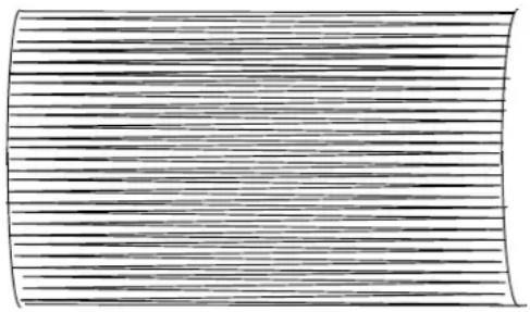
Figure 3-2 Raster Scan Pattern
High Density Single Scan Line Scan Pattern
The High Density single scan line appears as a "mini" raster and scans multiple areas of 1D codes to swiftly and accurately capture data on poorly printed and damaged bar codes.
Figure 3-3 High Density Single Scan Line Scan Pattern
Symbol MS3207 Scan Patterns
The Symbol MS3207 generates four scan patterns based on the software command received at the interface. These patterns are Smart Raster, Semi-omnidirectional, Omnidirectional, and High Density Single Scan Line. Use the raster pattern to read 1D bar codes and PDF417 symbols. The omnidirectional pattern reads 1D bar codes in an omnidirectional manner.
Smart Raster Scan Pattern
The Symbol MS3207 can create a single line which opens vertically to read PDF417 symbols using the Smart Raster feature. This feature autodetects the type of bar code being scanned and adjusts its pattern accordingly, providing optimal performance on 1D, PDF417, GS1 DataBar, and Composite codes.
Stage 1: "Slab" Raster Pattern
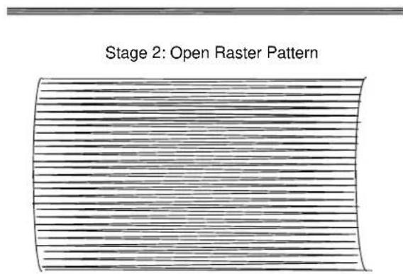
Figure 3-4 Raster Scan Pattern
Semi-omnidirectional Scan Pattern
The semi-omnidirectional pattern is an alternative to the full omnidirectional pattern that scans highly truncated 1D and GS1 DataBar codes. Present bar codes horizontally with no more than a 20irc tilt.
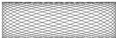
natural_image
Pure geometric pattern of interlocking diamond shapes without any text, numbers, or symbolsFigure 3-5 Semi-omnidirectional Scan Pattern
Omnidirectional Scan Pattern
The high-speed rotating omnidirectional scan pattern provides aggressive performance on 1D bar codes because there are no “holes” in the pattern. This ensures fast throughput at the point of activity and the ability to read 1D symbols in 360° of rotation, eliminating the need to orient the bar code in the field of view.

natural_image
Abstract geometric pattern composed of intersecting lines forming a spherical structure (no text or symbols)Figure 3-6 Omnidirectional Scan Pattern
High Density Single Scan Line Scan Pattern
The High Density single scan line appears as a "mini" raster and scans multiple areas of 1D codes to swiftly and accurately capture data on poorly printed and damaged bar codes.
Figure 3-7 High Density Single Scan Line Scan Pattern
Scan Angle Selection
The Symbol MS1207FZY scanner supports two scan angles (see Table 4-2 on page 4-5 for these angles). To set the scan angle, scan a parameter bar code (see Scan Angle on page 10-10). Once the parameter bar code is scanned, that scan angle setting is retained.
Operation in Blink Mode
The scan angle during Blink Mode is determined by the scan angle system parameter.
Scanning Tips
When scanning, make sure the symbol is within the scanning range. See Calculating the Usable Scan Length Method on page 2-8. Align the bar code with the scan beam. The green decode LED lights to indicate a successful decode.
Scan the Entire Symbol
- The scan beam must cross every bar and space on the symbol.
- The larger the symbol, the farther away the scanner should be positioned.
- Position the scanner closer for symbols with bars that are close together.


Position at an Angle
Do not position the scanner exactly perpendicular to the bar code. In this position, light can bounce back into the scanner's exit window and prevent a successful decode.
Trigger Options
Continuous (Default)
The laser is enabled continuously and decode processing is continuously active. You can configure the scanner to scan and transmit a bar code, and then not decode the same bar code or any bar code for a set period of time. See Timeout Between Decodes on page 10-15 to customize the application to the rate at which bar codes are presented.
Continuous

NOTE This option is not recommended during scanner programming via bar code menus.
Level Trigger
Activating the trigger line enables the laser and begins decode processing. Decode processing continues until a good decode occurs, the trigger is released, or the Laser On Time expires. The laser is disabled once decode processing completes. The next decode attempt does not occur until the trigger line is released and then reactivated.
Level
Pulse Trigger
Activating the trigger line enables the laser and begins decode processing. Decode processing continues regardless of the trigger line until a good decode occurs, or until the Laser On Time expires. The laser is disabled once decode processing completes. The next decode attempt does not occur until the trigger line is released and then reactivated.

Pulse
Blink

NOTE Only the Symbol MS1207FZY and MS1207WA support this option.
The laser blinks at a 25% duty cycle (reduced to 10% after 30 seconds of inactivity), until a bar code is presented. When a bar code is presented, the laser remains on until either the bar code is decoded or removed, or the session timeout expires. Once the bar code is decoded, the scanner does not decode it again until the bar code is removed.
Blink
Beeper and LED Definitions
Table 3-1 provides standard beeper definitions, and Table 3-2 provides LED definitions.
Table 3-1 Standard Beeper Definitions
| Beeper Sequence Indication | |
| Standard Use | |
| 1 Beep - short high tone A bar code symbol | was decoded (if decode beeper is enabled). |
| 1 Beep - long high tone Thermal shutdown. | |
| 3 Beeps - short high tone(Symbol MS2207/2207VHD/3207 only) | Power-on or reset. Occurs immediately after the scanner is turned on, indicating that the system software is working properly. If three beeps occur during normal operation, it is due to a reset and any work in progress is lost. If this occurs often, contact Motorola Enterprise Mobility Support. |
| Parameter Menu Scanning | |
| 2 Beeps- short high tone Correct entry scanned or correct menu sequence performed. | |
| 1 Beep- hi/lo/hi/lo tone Successful program exit with change in the parameter setting. | |
| 2 Beeps - lo/hi tone | Input error, incorrect bar code, or Cancel scanned, wrong entry, incorrect bar code programming sequence; remain in program mode. |
| Communication | |
| 4 Beeps - short high tone Communication error. | |
| 4 Beeps - hi/hi/hi/lo Receive error. | |
| 3 Beeps - lo/hi/lo ADF transmit error. | |
Table 3-2 LED Definitions
| LED Indication | |
| Red Scanner is on. | |
| Green | A bar code was successfully decoded. |
3 - 8 Symbol MiniScan MSXX07 Series Integration Guide
Chapter 4 Symbol MS1207FZY Specifications
Introduction
This chapter provides the technical specifications for the Symbol MS1207FZY scanner.
Symbol MS1207FZY Electrical Interface
natural_image
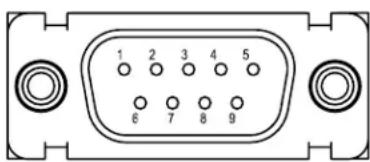
Front view of a 16-pin electronic component (no text or symbols visible)Figure 4-1 MiniScan Connector
Table 4-1 lists the pin functions of the Symbol MS1207FZY interface.
Table 4-1 Symbol MS1207FZY Electrical Interface
| Pin No. | Pin Name Type* Function | ||
| 1 Trigger | I Signals scanner to begin scanning session. | ||
| 2 TXD O | Serial data transmit output. Drives the serial data receive input on the device communicating with the scanner. | ||
| 3 RXD I | Serial data receive input. Driven by the serial data transmit output on the device communicating with the scanner. | ||
| 4 Not used | |||
| 5 Ground | Power supply ground input and signal ground reference. | ||
| 6 Power | I 5.0 VDC ± 10% | ||
| 7 CTS I | Clear-to-send handshaking input line, used only in conjunction with the RTS line. Optionally used by another device to signal the scanner to begin transmitting data. | ||
| 8 RTS O | Request-to-send handshaking output line, used only in conjunction with the CTS line. Optionally used by the scanner to signal another device that data is available to send. | ||
| 9 | Beeper/Download | I/O | During normal operation this signal functions as an external beeper drive line. This signal can sink 50 mA of current to drive an external beeper, and is normally pulled up. This signal is also used to begin Flash Download operation when grounded externally during power up. |
*I = Input 0 = Output
Symbol MS1207FZY Mechanical Drawings
![DB9 CONNECTOR .12 [3] FRONT OF SCAN ENGINE SCANNING FIELD NOMINAL SCAN LINE 1.60 [41] .70 [18] (.20) [5] .97 [25] .88 [22] 10.0° 10.0° COLLECTION FIELD 2.94 [75]](/content/2026/05/1068115/images/e9c9101d31759002fbfdd2413d92ab8db889ecad57cff7bb76c27c41cda963ee.jpg)
Notes:
Unless otherwise specified:
- Dimensions are in inches, dimensions in [ ] are mm.
- User mounting tolerances are not included.
![2.28 [58]](/content/2026/05/1068115/images/8e4f88f4d27669cca22f8157ded3a7c1167c040352aee87bc4c3aadcc0c18f07.jpg)
Figure 4-2 Symbol MS1207FZY Mechanical Drawing
![.20 TYPICAL COLLECTION FIELD 51.0° 42.0° .04 [1] NOMINAL SCAN ANGLE SCANNING FIELD .75 [19] .97 [25] .20 [5] MFG. LABEL 3X M3 - 3.6 MM LG. MAX MOUNTING SCREW HOLES 1.12 [28] FRONT OF SCAN ENGINE (.39) [10] 1.50 [38]](/content/2026/05/1068115/images/1ff29dc95b95abf10c5da90bda46f1ff302185be5dfce85e74b80859f51d059f.jpg)
Notes:
Unless otherwise specified:
- Dimensions are in inches, dimensions in [ ] are mm.
- User mounting tolerances are not included.

natural_image
Line drawing of a microwave oven with control panel and display (no text or symbols)Figure 4-3 Symbol MS1207FZY Mechanical Drawing
Symbol MS1207FZY Technical Specifications
Table 4-2 provides the Symbol MS1207FZY technical specifications.
Table 4-2 Symbol MS1207FZY Technical Specifications @ 23°C
| Item Description | |
| Power Requirements | |
| Input Voltage | 5.0 VDC ±10% |
| Scanning Current | 160 mA ±40 mA |
| Standby Current | 20 mA ±5 mA typical |
| Vcc Noise Level | 200 mV peak-to-peak max. |
| Laser Power 1.0 mW ± 0.12 mW, λ = 650 nm nominal | |
| Scan Rate 36 (± 5) scans/sec (bidirectional) | |
| Print Contrast Minimum 25% absolute dark/light reflectance measured at 650 nm. | |
| Scan Angle Default (Wide): 42° ± 2°Alternate (Narrow): 30° ± 2° | |
| Scan Pattern Single scan line | |
| Skew Tolerance ± 50° from normal (see Figure 4-4 on page 4-6) | |
| Pitch Angle ± 65° from normal (see Figure 4-4 on page 4-6) | |
| Roll ± 20° from vertical (see Figure 4-4 on page 4-6) | |
| Decode Depth of Field See Figure 4-5 on page 4-7 | |
| Ambient Light Immunity Sunlight Artificial Light | 8,000 ft. candles (86,112 lux)450 ft. candles (4,844 lux) |
| Drop Multiple 30" drops | |
| Vibration | Unpowered scanner withstands a random vibration along each of the X,Y and Z axes for a period of one hour per axis, defined as follows:20 to 80 Hz Ramp up to 0.04 G^2/Hz at the rate of 3dB/octave.80 to 350 Hz 0.04 G^2/Hz350 to 2000 Hz Ramp down at the rate of 3 dB/octave. |
| ESD | ± 20kV air discharge± 8kV indirect discharge |
| Sealing | IP54 |
| Operating Temperature | -4° to 122°F (-20° to 50°C) |
| Storage Temperature | -40° to 158°F (-40° to 70°C) |
| Humidity | 5% to 95% non-condensing |
| Item Description | |
| Laser Class CDRH Class II, IEC Class 2 | |
| Height 1.60 in. (4.06 cm) | |
| Width 2.28 in. (5.79 cm) | |
| Depth 2.94 in. (7.47 cm) | |
| Weight 4.45 oz. (126 gm) | |
Note: Environmental and/or tolerance parameters are not cumulative.

Figure 4-4 Skew, Pitch and Roll
Symbol MS1207FZY Decode Zone
The scanner has a selectable scan angle of either 30irc or 42irc . Figure 4-5 shows the 42irc symbol decodes. The figures shown are typical values. Table 4-3 on page 4-8 lists the typical and guaranteed distances for the 42irc scan angle for selected bar code densities. The minimum element width (or “symbol density”) is the width in mils of the narrowest element (bar or space) in the symbol. The maximum usable length of a symbol at any given range appears below. To calculate this distance, see Calculating the Usable Scan Length Method on page 2-8.

other
| Label | Value | | ------------- | ------- | | MS-120XFZY | 5 mil | | | 7.00 | | | 7.5 mil | | | 12.50 | | | 25.75 | | | 34.00 | | | 40 mil | | | 55 mil | | | 66.75 | | | 75.00 |Figure 4-5 Symbol MS1207FZY Typical Decode Zone (42° Scan Angle)
Table 4-3 Symbol MS1207FZY Decode Distances ( 42irc Scan Angle)
| Symbol Density/p/n / Bar Code Type/W-N Ratio | Bar Code Content/Contrast1 | Typical Working Ranges3 | Guaranteed Working Ranges3 | ||
| Near Far | Near Far | ||||
| 5.0 mil64-17453-01Code 39; 2.5:1 | ABCDEFGH80% MRD | 3.25 in.8.26 cm | 7.00 in.17.78 cm | 4.75 in.12.07 cm | 5.25 in.13.34 cm |
| 7.5 mil64-17452-01Code 39; 2.5:1 | ABCDEF80% MRD | 3.00 in.7.62 cm | 12.50 in.31.75 cm | 4.75 in.12.07 cm | 9.00 in.22.86 cm |
| 13 mil64-05303-01100% UPC | 01234567890580% MRD | 2.20 in.5.59 cm | 25.75 in.65.41 cm | Note 2 19.00 in. | 48.26 cm |
| 20 mil60-01429-01Code 39; 2.2:1 | 12380% MRD | 1.00 in.2.54 cm(Note 2) | 34.00 in.86.36 cm | Note 2 | 24.00 in.60.96 cm |
| 20 mil60-02710-01Code 39; 2.2:1 | 12325% MRD | 1.00 in.2.54 cm(Note 2) | 27.25 in.69.22 cm | Note 2 | 22.00 in.55.88 cm |
| 40 mil64-17457-01Code 39; 2.2:1 | AB80% MRD | 2.20 in.5.59 cm(Note 2) | 66.75 in.169.55 cm | Note 2 49.00 in. | 124.46 cm |
| 55 mil64-17458-01Code 39; 2.2:1 | CD80% MRD | 4.00 in.10.16 cm(Note 2) | 75.00 in.190.50 cm | Note 2 55.00 in. | 139.70 cm |
Notes:
-
Contrast measured as Mean Reflective Difference (MRD) at 650 nm.
-
Near ranges on lower densities largely depend on the width of the bar code and the scan angle.
-
Working range specifications: Photographic quality symbols, pitch = 10°, skew = 0°, roll = 0°, ambient light < 150 ft. candles, and temperature = 23 °C.
Usable Scan Length
The decode zone is a function of various symbol characteristics including density, print contrast, wide-to-narrow ratio, and edge accuracy. Consider the width of the scan line at any given distance when designing a system.
Calculating the Usable Scan Length Method on page 2-8 describes how to calculate the usable scan length. The scan angle is provided in Table 4-2 on page 4-5.
Chapter 5 Symbol MS1207WA Specifications
Introduction
This chapter provides the technical specifications for the Symbol MS1207WA scanner.
Symbol MS1207WA Electrical Interface
natural_image
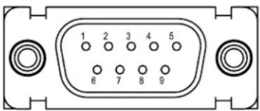
Front view of a 2-pin electronic component with labeled pins (no text or symbols beyond pin numbers)Figure 5-1 MiniScan Connector
Table 5-1 lists the pin functions of the Symbol MS1207WA.
Table 5-1 Symbol MS1207WA Electrical Interface
| Pin No. | Pin Name Type* | Function | |
| 1 Trigger I | Signals scanner to begin scanning session. | ||
| 2 TXD O | Serial data transmit output. Drives the serial data receive input on the device communicating with the scanner. | ||
| 3 | RXD/D+ | I/O | RS-232 Mode: Serial data receive input. Driven by the serial data transmit output on the device communicating with the scanner.USB Mode: D+ signal. During USB operation this signal is pulled up by a 1.5k Ohm resistor to begin USB enumeration. In this mode it is a differential bi-directional signal. |
| 4 | SYN_CLK | I/O | Synapse Mode: Synapse Clock line. Signal used as a clock by a Synapse host. Pin is shorted to RTS/SYN_DAT in USB cables to allow auto-detection of USB mode via signal loopback. |
| 5 Ground Power supply ground input and signal ground reference. | |||
| 6 Power | 5.0 VDC ± 10% | ||
| 7 | CTS/D- | I/O | RS-232 Mode: Clear-to-send handshaking input line, used only in conjunction with the RTS line. Optionally used by another device to signal the scanner to begin transmitting data.USB Mode: D- signal. During USB operation this signal works in conjunction with the D+ signal as a differential bi-directional signal. |
| 8 | RTS/SYN_DAT | I/O | RS-232 Mode: Request-to-send handshaking output line, used only in conjunction with the CTS line. Optionally used by the scanner to signal another device that data is available to send.Synapse Mode: Synapse Data line. Used to transmit data to and from a Synapse host. |
| 9 Beeper/Download I/O During normal operation this signal functions as an external beeper drive line. This signal can sink 50mA of current to drive an external beeper, and is normally pulled up. This signal is also used to begin Flash Download operation when grounded externally during power up. | |||
*I = Input 0 = Output
Symbol MS1207WA Mechanical Drawings
![DB9 CONNECTOR .12 [3] FRONT OF SCAN ENGINE SCANNING FIELD NOMINAL SCAN LINE 1.60 [41] .70 [18] (.20) [5] .97 [25] .88 [22] 10.0° 10.0° COLLECTION FIELD 2.94 [75]](/content/2026/05/1068115/images/c044a3417d75a3b570c78723a25403c2f894d9e7655914fb34afa91a7ab4b41d.jpg)
Notes:
Unless otherwise specified:
- Dimensions are in inches, dimensions in [ ] are mm.
- User mounting tolerances are not included.
![2.28 [58]](/content/2026/05/1068115/images/40aa2c7d1f00782e4fac5874e19b22de77d01f83bfaff82013e6f23267793c71.jpg)
Figure 5-2 Symbol MS1207WA Mechanical Drawing
![.19 TYPICAL COLLECTION FIELD 68.0° 60.0° .04 [1] SCANNING FIELD NOMINAL SCAN ANGLE .75 [19] .97 [25] 1.12 [28] .20 [5] MFG. LABEL 3X M3 - 3.6 MM LG. MAX MOUNTING SCREW HOLES FRONT OF SCAN ENGINE .75 [19] 1.50 [38] (.39) [10]](/content/2026/05/1068115/images/600fdffc36525ff523a34daf1ce1286636306fd0020943bad11efdcc732e7423.jpg)
Notes:
Unless otherwise specified:
- Dimensions are in inches, dimensions in [ ] are mm.
- User mounting tolerances are not included.

natural_image
Line drawing of a microwave oven with control panel and display screen (no text or symbols)Figure 5-3 Symbol MS1207WA Mechanical Drawing
Symbol MS1207WA Technical Specifications
Table 5-2 provides the Symbol MS1207WA technical specifications.
Table 5-2 Symbol MS1207WA Technical Specifications @ 23°C
| Item Description | |
| Power Requirements | |
| Input Voltage | 5.0 VDC ± 10% |
| Scanning Current | 110 mA ± 30mA |
| Standby Current | 40 mA ± 5 mA typical |
| Vcc Noise Level | 200 mV peak-to-peak max. |
| Laser Power 0.48 mW ± 0.05 | mW, λ = 670 nm nominal |
| Scan Rate 36 (± 5) scans/sec | (bidirectional) |
| Print Contrast Minimum 20% | absolute dark/light reflectance measured at 670 nm. |
| Scan Angle 60° ± 2° | |
| Scan Pattern Single scan line | |
| Skew Tolerance ± 65° from normal | (see Figure 5-4 on page 5-6) |
| Pitch Angle ± 55° from normal | (see Figure 5-4 on page 5-6) |
| Roll ± 20° from vertical (see | Figure 5-4 on page 5-6) |
| Decode Depth of Field See | Figure 5-5 on page 5-7 |
| Ambient Light Immunity | |
| Sunlight | 8,000 ft. candles (86,112 lux) |
| Artificial Light | 450 ft. candles (4,844 lux) |
| Drop Multiple 30" drops | |
| Vibration | Withstands a sinusoidal vibration of 1 G along each of the 3 mutually perpendicular axes for a period of 1 hr per axis, over a frequency range of 5 Hz to 2000Hz. |
| ESD | ± 20kV air discharge± 8kV indirect discharge |
| Sealing | IP54 |
| Operating Temperature | 32° to 104°F (0° to 40°C) |
| Storage Temperature | -40° to 140°F (-40° to 60°C) |
| Humidity | 5% to 95% non-condensing |
| Laser Class | CDRH Class II, IEC Class 2 |
| Height | 1.60 in. (4.06 cm) |
| Item Description | |
| Width 2.28 in. (5.79 cm) | |
| Depth 2.94 in. (7.47 cm) | |
| Weight 4.45 oz. (126 gm) | |
Note: Environmental and/or tolerance parameters are not cumulative.

Figure 5-4 Skew, Pitch and Roll
Symbol MS1207WA Decode Zone
Figure 5-5 shows the Symbol MS1207WA Wide Angle decode symbols. Typical values appear. Table 5-3 on page 5-8 lists the typical and guaranteed distances for selected bar code densities. The minimum element width (or "symbol density") is the width in mils of the narrowest element (bar or space) in the symbol. The maximum usable length of a symbol at any given range is shown below. To calculate this distance, see Calculating the Usable Scan Length Method on page 2-8.

other
| Depth of Field | Width (cm) | Width (ft) | Width (h) | | -------------- | ---------- | ---------- | --------- | | 0 | 12.4 | 31.6 | 6 | | 5 | 15.2 | 6 | 0 | | 10 | 15.2 | 6 | 6 | | 15 | 15.2 | 6 | 12.4 | | 20 | 15.2 | 6 | 31.6 | | 25 | 15.2 | 6 | 63.5 | | 30 | 15.2 | 6 | 63.5 | | 35 | 15.2 | 6 | 63.5 | | 40 | 15.2 | 6 | 63.5 | | 45 | 15.2 | 6 | 63.5 | | 50 | 15.2 | 6 | 63.5 | | 55 | 15.2 | 6 | 63.5 | | 60 | 15.2 | 6 | 63.5 | | 65 | 15.2 | 6 | 63.5 | | 70 | 15.2 | 6 | 63.5 | | 75 | 15.2 | 6 | 63.5 | | 80 | 15.2 | 6 | 63.5 | | 85 | 15.2 | 6 | 63.5 | | 90 | 15.2 | 6 | 63.5 | | 95 | 15.2 | 6 | 63.5 | | 100 | 15.2 | 6 | 63.5 | | Minimum distance determined by symbol length and scan angle * Minimum distance determined by symbol length and scan angleFigure 5-5 Symbol MS1207WA Decode Zone (Typical)
Table 5-3 . Symbol MS1207WA Decode Distances
| Symbol Density/p/n / Bar Code Type/W-N Ratio | Bar Code Content/Contrast1 | Typical Working Ranges | Guaranteed Working Ranges | ||
| Near Far | Near Far | ||||
| 5 mil64-17453-01Code 39; 2.5:1 | ABCDEFGH80% MRD | 1.0 in.2.54 cm | 4.0 in.10.16 cm | 1.2 in.3.05 cm | 3.0 in.7.62 cm |
| 7.5 mil64-17452-01Code 39; 2.5:1 | ABCDEF80% MRD | 0.6 in.1.52cm | 7.2 in.8.29 cm | 0.9 in.2.29cm | 6.0 in.15.24 cm |
| 13 mil64-05303-01100% UPC | 123456789080% MRD | 0.6 in.1.52 cm | 11.0 in.27.94 cm | 0.9 in.2.29 cm | 9.0 in.22.86 cm |
| 20 mil60-01429-01Code 39; 2.2:1 | 12380% MRD | Note 2 | 15.0 in.38.10 cm | Note 2 | 13.0 in.33.02 cm |
| 40 mil64-17457-01Code 39; 2.2:1 | AB80% MRD | Note 2 | 19.0 in.48.26 cm | Note 2 | 17.0 in.3.18 cm |
| 55 mil64-17458-01Code 39; 2.2:1 | CD80% MRD | Note 2 | 24.0 in.60.96 cm | Note 2 | 22.0 in.55.88 cm |
-
Contrast measured as Mean Reflective Difference (MRD) at 670 nm.
-
Near ranges on lower densities (not specified) largely depend on the width of the bar code and the scan angle.
-
Working range specifications at ambient temperature 23 °C.
Usable Scan Length
The decode zone is a function of various symbol characteristics including density, print contrast, wide-to-narrow ratio, and edge acuity. Consider width of decode zone at any given distance when designing a system.
Calculating the Usable Scan Length Method on page 2-8 describes how to calculate the usable scan length. The scan angle is provided in Table 5-2 on page 5-5.
Chapter 6 Symbol MS2207 Specifications
Introduction
This chapter provides the technical specifications for the Symbol MS2207 scanner.
Symbol MS2207 Electrical Interface

natural_image
Front view of a 2-pin electronic connector (no text or symbols visible)Figure 6-1 MiniScan Connector
Table 6-1 lists the pin functions of the Symbol MS2207 interface.
Table 6-1 Symbol MS2207 Electrical Interface
| Pin No. | Pin Name Type* Function | ||
| 1 Trigger I | Signals scanner to begin scanning session. | ||
| 2 TXD O | Serial data transmit output. Drives the serial data receive input on the device communicating with the scanner. | ||
| 3 | RXD/D+ | I/O | RS232 Mode: Serial data receive input. Driven by the serial data transmit output on the device communicating with the scanner.USB Mode: D+ signal. During USB operation this signal is pulled up by a 1.5k Ohm resistor to begin USB enumeration. In this mode it is a differential bi-directional signal. |
| 4 | SYN_CLK | I/O | Synapse Mode: Synapse Clock line. Signal used as a clock by a Synapse host. Pin is shorted to RTS/SYN_DAT in USB cables to allow autodetection of USB mode via signal loopback. |
| 5 Ground | Power supply ground input and signal ground reference. | ||
| 6 Power | 5.0 VDC ± 10% | ||
| 7 | CTS/D- | I/O | RS232 Mode: Clear-to-send handshaking input line, used only in conjunction with the RTS line. Optionally used by another device to signal the scanner to begin transmitting data.USB Mode: D- signal. During USB operation this signal works in conjunction with the D+ signal as a differential bi-directional signal. |
| 8 | RTS/SYN_DAT | I/O | RS232 Mode: Request-to-send handshaking output line, used only in conjunction with the CTS line. Optionally used by the scanner to signal another device that data is available to send.USB Mode: Synapse Data line. Signal is used to transmit data to and from a Synapse host. |
| 9 Beeper/Download | I/O During normal operation this signal functions as an external beeper drive line. This signal can sink 50mA of current to drive an external beeper, and is normally pulled up. This signal is also used to begin Flash Download operation when grounded externally during power up. | ||
*I = Input 0 = Output
Symbol MS2207 Mechanical Drawings
![DB9 CONNECTOR FRONT OF CHASSIS 1.60 [41] .70 [18] .80 [20] .97 [25] 2.94 [75] VERTICAL 2D SCANNING FIELD .11 COLLECTION FIELD NOMINAL SCAN ANGLE 2D 12.5° 7.0° 20.0° NOMINAL SCAN LINE (1D) VERTICAL 1D SCANNING FIELD .88 [22]](/content/2026/05/1068115/images/89c89e206d06f3a42785f8ce6285da9eb62f6f72a83a118162721614b17100b4.jpg)
Notes:
Unless otherwise specified:
- Dimensions are in inches, dimensions in [ ] are mm.
- User mounting tolerances are not included.
![2.28 [58]](/content/2026/05/1068115/images/3008c8e4efb1877c17d19ee561bbb2e18cdba2ef65280c0523088f5c6e6ca23b.jpg)
Figure 6-2 Symbol MS2207 Mechanical Drawing
![43.0° 34.0° NOMINAL SCAN ANGLE HORIZONTAL 1D AND 2D SCANNING FIELD .10 HORIZONTAL COLLECTION FIELD .13 HORIZONTAL COLLECTION FIELD .75 [19] .97 [25] 1.12 [28] .56 [14] MFG. LABEL FRONT OF SCAN ENGINE .04 [1] .75 [19] 1.50 [38] (.39) [10] 3X M3 - 3.6 MM LG. MAX MOUNTING SCREW HOLES](/content/2026/05/1068115/images/bf69bd69eafa1d15bb4c0cdbdd92dad89057d64b7b21500e68639723589c0e37.jpg)
Notes:
Unless otherwise specified:
- Dimensions are in inches, dimensions in [ ] are mm.
- User mounting tolerances are not included.
natural_image
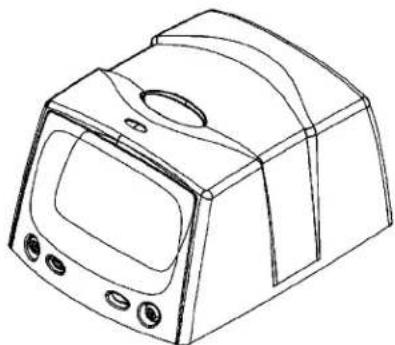
Line drawing of a microwave oven with control panel and buttons (no text or symbols)Figure 6-3 Symbol MS2207 Mechanical Drawing
Symbol MS2207 Technical Specifications
Table 6-2 provides the Symbol MS2207 technical specifications
Table 6-2 Symbol MS2207 Technical Specifications @ 23°C
| Item Description | |
| Power Requirements | |
| Input Voltage | 5.0 VDC ± 10% |
| Scanning Current | 250 ± 30 mA typical |
| Standby Current | 45 ± 5 mA typical |
| Vcc Noise Level | 200 mV peak-to-peak max. |
| Laser Power 0.95 mW ± 0.1 mW, | λ = 650 nm nominal |
| Scan Rate 640 scans/sec. | |
| Scan Frequency: Horizontal 320 Hz ± 5 Hz | |
| Scan Frequency: Vertical 282 Hz ± 5 Hz | |
| Frame Rate 24 frames/sec. 12 Hz ±1 Hz (vertical) | |
| Print Contrast Minimum 35% absolute dark/light reflectance differential | |
| Scan Angle | Horizontal: 34° ±1.5°Vertical: 34° ±1.5° |
| Scan Pattern Smart raster, high density single scan line | |
| Start Time 0.065 sec. to 75% of steady state horizontal amplitude | |
| Skew Tolerance | ± 15° from plane parallel to symbol (see Figure 6-4 on page 6-7) |
| Pitch Angle | ± 30° from normal (see Figure 6-4 on page 6-7) |
| Roll | ± 4° from (for scanning benchmark label, assuming 3:1 codeword aspect ratio)(see Figure 6-4 on page 6-7) |
| Decode Depth of Field See | Figure 6-5 on page 6-8 |
| Beam Deviation(offset from the nominal) | Horizontal: ±3.0°Vertical: ±3.0°Horizontal tilt: ± 2° |
| Ambient Light Immunity | |
| Sunlight | 8,000 ft. candles (86,112 lux) |
| Artificial Light | 450 ft. candles (4,844 lux) |
| Drop | Multiple 30" drops |
| Item | Description |
| Vibration Unpowered scanner withstands a random vibration along each of the X, Y and Z axes for a period of one hour per axis, defined as follows:20 to 80 Hz Ramp up to 0.04 G^2/Hz at the rate of 3dB/octave.80 to 350 Hz 0.04 G^2/Hz350 to 2000 Hz Ramp down at the rate of 3 dB/octave. | |
| ESD ± 20kV air discharge | ± 8kV indirect discharge |
| Sealing IP54 | |
| Operating Temperature -22° to 122°F (-30° to 50°C) | |
| Storage Temperature -40° to 158°F (-40° to 70°C) | |
| Humidity 5% to 95% non-condensing | |
| Laser Class CDRH Class II, IEC Class 2 | |
| Height 1.60 in. (4.06 cm) | |
| Width 2.28 in. (5.79 cm) | |
| Depth 2.94 in. (7.47 cm) | |
| Weight | 4.73 oz. (134 gm) |

Note: Tolerances are reduced at extreme ends of the working range.
Figure 6-4 Skew, Pitch and Roll
Symbol MS2207 Decode Zones
The decode zone is a function of various symbol characteristics including density, print contrast, wide to narrow ratio and edge acurity. Typical values appear. Table 6-3 on page 6-9 and Table 6-4 on page 6-11 list the typical and guaranteed distances for selected bar code densities. The minimum element width (or "symbol density") is the width in mils of the narrowest element (bar or space) in the symbol. The maximum usable length of a symbol at any given range appears below. To calculate this distance, see Calculating the Usable Scan Length Method on page 2-8.
Symbol MS2207 1D Decode Zone

other
| Depth of Field | Minimum Element Width (cm) | | -------------- | --------------------------- | | 0 | 12.7 | | 5 | 25.4 | | 10 | 38.1 | | 15 | 50.8 | | 20 | 19.0 | | 25 | 24.0 | | 30 | 31.0 | | 35 | 88.9 |* Minimum distance determined by symbol length and scan angle.
Figure 6-5 Symbol MS2207 1D Decode Distances
Symbol MS2207 1D Decode Distances
Table 6-3 Symbol MS2207 1D Decode Distances
| Symbol Density/p/n / Bar Code Type | Bar Code Content/Contrast1 | Typical Working Ranges3 | Guaranteed Working Ranges3 | ||
| Near Far | Near Far | ||||
| 6.0 mil60-01755-01Code 39 | 12380% MRD | 2.0 in.5.08 cm | 5.25 in.13.34 cm | 2.75 in.7.00 cm | 4.0 in.10.16 cm |
| 7.5 mil64-17452-01Code 39 | ABCDEF80% MRD | 1.5 in.3.81 cm | 7.0 in.17.78 cm | 2.25 in.5.72 cm | 5.0 in.12.7 cm |
| 13 mil64-05303-01100% UPC | 01234567890580% MRD | Note 2 14.0 in. | 35.56 cm | N/A 10.5 in. | 26.67 cm |
| 20 mil64-17456-01Code 39 | 12380% MRD | Note 2 19.0 in. | 48.26 cm | N/A 14.0 in. | 35.56 cm |
| 40 mil64-17457-01Code 39 | AB80% MRD | Note 2 24.0 in. | 60.96 cm | N/A 18.0 in. | 45.72 cm |
| 55 mil60-01601-01Code 39 | A80% MRD | Note 2 31.0 in. | 78.74 cm | Note 2 25.0 in. | 63.50 cm |
Notes:
-
Contrast measured as Mean Reflective Difference (MRD) at 650 nm.
-
Near ranges on lower densities largely depend on the width of the bar code and the scan angle.
-
Working range specifications: Photographic quality symbols, pitch = 10°, skew = 0°, roll = 0°, ambient light < 150 ft. candles, and temperature = 23 °C.
Symbol MS2207 2D Decode Zone
Note: Typical performance at 68irc F ( 20irc C) on high quality symbols
in normal room light. Y-module dimension = 3X.
Vcc = 5V
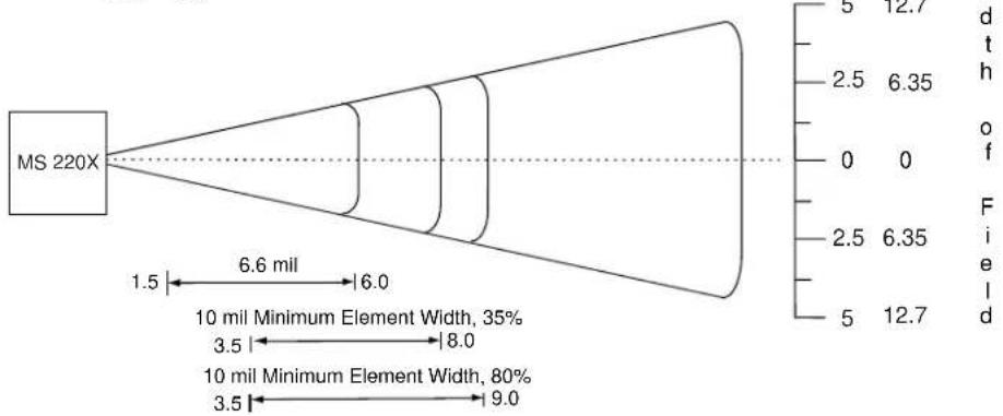
other
| Dimension | Value | | --------- | ----- | | d | 12.7 | | t | 6.35 | | h | 0 | | o | 0 | | f | 2.5 | | f | 6.35 | | i | 5 | | e | 12.7 | | l | 12.7 | | d | 12.7 | | d | 6.6 mil | | t | 6.0 | | t | 3.5 mil | | o | 3.5 | | f | 8.0 | | f | 10 mil Minimum Element Width | | i | 3.5 | | i | 9.0 |
line
| Depth of Field | Value | |---|---| | 0 | 0 | | 2 | 5.1 | | 4 | 10.1 | | 6 | 15.2 | | 8 | 20.3 | | 10 | 25.4 | | 12 | 30.5 | | 14 | 35.6 | | 16 | 40.6 | | 5.6 (15 mil Minimum Element Width) | 5.6 | | 15.0 | |Figure 6-6 Symbol MS2207 2D Slab/Raster Decode Distances

NOTE Not optimized for omnidirectional mode.
Symbol MS2207 2D Decode Distances
Table 6-4 Symbol MS2207 2D Slab/Raster Decode Distances
| Symbol Density/p/n / Bar Code Type | Bar Code Content/Contrast1 | Typical Working Ranges3 | Guaranteed Working Ranges3 | ||
| Near Far | Near Far | ||||
| 6.6 mil64-14035-01PDF417 | ABCDEF80% MRD | 1.5 in.3.81 cm | 6.00 in.15.24 cm | Note 2 4.75 in. | 12.07 cm |
| 10 mil64-14937-01PDF417 | 01234567890535% MRD | 3.5 in.8.89 cm | 8.0 in.20.32 cm | Note 2 5.0 in. | 12.7 cm |
| 10 mil64-14037-01PDF417 | 80% MRD 3.5 in. | 8.89 cm | 9.0 in.22.86 cm | Note 2 7.5 in. | 19.05 cm |
| 15 mil64-14038-01PDF417 | 80% MRD 5.6 in. | 14.22 cm | 15.0 in.38.10 cm | Note 2 13.0 in. | 33.02 cm |
Notes:
1. Contrast measured as Mean Reflective Difference (MRD) at 650 nm.
2. Near ranges on lower densities largely depend on the width of the bar code and the scan angle.
3. Working range specifications: Photographic quality symbols, pitch = 10°, skew = 0°, roll = 0°, ambient light < 150 ft. candles, and temperature = 23 °C.

NOTE Not optimized for omnidirectional mode.
Usable Scan Length
The decode zone is a function of various symbol characteristics including density, print contrast, wide-to-narrow ratio, and edge acuity. Consider width of decode zone at any given distance when designing a system.
Calculating the Usable Scan Length Method on page 2-8 describes how to calculate the usable scan length.
Chapter 7 Symbol MS2207VHD Specifications
Introduction
This chapter provides the technical specifications for the Symbol MS2207VHD scanner.
Symbol MS2207VHD Electrical Interface

natural_image
Front view of a 2-pin electronic connector (no text or symbols visible)Figure 7-1 MiniScan Connector
Table 7-1 lists the pin functions of the Symbol MS2207VHD.
Table 7-1 Symbol MS2207VHD Electrical Interface
| Pin No. | Pin Name Type*Function | ||
| 1 Trigger | Signals scanner to begin scanning session. | ||
| 2 TXD O | Serial data transmit output. Drives the serial data receive input on the device communicating with the scanner. | ||
| 3 RXD I | Serial data receive input. Driven by the serial data transmit output on the device communicating with the scanner. | ||
| 4 Not used | |||
| 5 Ground | Power supply ground input and signal ground reference. | ||
| 6 Power I | 5.0 VDC ± 10% | ||
| 7 CTS I | Clear-to-send handshaking input line, used only in conjunction with the RTS line. Optionally used by another device to signal the scanner to begin transmitting data. | ||
| 8 RTS O | Request-to-send handshaking output line, used only in conjunction with the CTS line. Optionally used by the scanner to signal another device that data is available to send. | ||
| 9 | Beeper/Download | I/O | During normal operation this signal functions as an external beeper drive line. This signal can sink 50mA of current to drive an external beeper, and is normally pulled up. This signal is also used to begin Flash Download operation when grounded externally during power up. |
*I = Input 0 = Output
Symbol MS2207VHD Mechanical Drawings
![DB9 CONNECTOR FRONT OF CHASSIS 1.60 [41] .70 [18] .80 [20] .97 [25] 2.94 [75] VERTICAL 2D SCANNING FIELD .11 COLLECTION FIELD NOMINAL SCAN ANGLE 2D 12.5° 7.0° 20.0° NOMINAL SCAN LINE (1D) VERTICAL 1D SCANNING FIELD .88 [22]](/content/2026/05/1068115/images/aa9371a53fcb76ac7a66b9338ed7ab305c9de3438e7c118514d2e334bd98bfc0.jpg)
Notes:
Unless otherwise specified:
- Dimensions are in inches, dimensions in [ ] are mm.
- User mounting tolerances are not included.
![2.28 [58]](/content/2026/05/1068115/images/65e568f5769dda7ec661897922299684317f81ffa410a0f70cdfc6bcccc2488a.jpg)
Figure 7-2 Symbol MS2207VHD Mechanical Drawing
![43.0° 34.0° NOMINAL SCAN ANGLE HORIZONTAL 1D AND 2D SCANNING FIELD .10 HORIZONTAL COLLECTION FIELD .75 [19] .97 [25] .13 HORIZONTAL COLLECTION FIELD .56 [14] MFG. LABEL .75 [19] .04 [1] 1.12 [28] .50 [38] (.39) [10] FRONT OF SCAN ENGINE 3X M3 - 3.6 MM LG. MAX MOUNTING SCREW HOLES](/content/2026/05/1068115/images/a3ffd5004264cbb363693009091c3ae1f582246d43eab62d09d98f5db61861a8.jpg)
Notes:
Unless otherwise specified:
- Dimensions are in inches, dimensions in [ ] are mm.
- User mounting tolerances are not included.

natural_image
Line drawing of a microwave oven with control panel and buttons (no text or symbols)Figure 7-3 Symbol MS2207VHD Mechanical Drawing
Symbol MS2207VHD Technical Specifications
Table 7-2 provides the Symbol MS2207VHD technical specifications.
Table 7-2 Symbol MS2207VHD Technical Specifications @ 23°C
| Item Description | |
| Power Requirements | |
| Input Voltage | 5.0 VDC ± 10% |
| Scanning Current | 250 ± 30 mA typical |
| Standby Current | 25 ± 5 mA typical |
| Vcc Noise Level | 200 mV peak-to-peak max. |
| Laser Power 0.7 mW ± 0.1 mW, | λ = 650 nm nominal |
| Scan Rate 640 scans/sec. | |
| Scan Frequency: Horizontal 320 Hz ± 5 Hz | |
| Scan Frequency: Vertical 282 Hz ± 5 Hz | |
| Frame Rate 24 frames/sec. 12 Hz ±1 Hz (vertical) | |
| Print Contrast Minimum 35% absolute dark/light reflectance differential | |
| Scan Angle | Horizontal: 34° ±3°Vertical: 12.5° ±3° |
| Scan Pattern Smart raster, high density single scan line | |
| Start Time 0.065 sec. to 75% of steady state horizontal amplitude | |
| Skew Tolerance | ± 15° from plane parallel to symbol (see Figure 7-4 on page 7-7) |
| Pitch Angle | ± 30° from normal (see Figure 7-4 on page 7-7) |
| Roll | ± 4° (for scanning benchmark label, assuming 3:1 codeword aspect ratio)(see Figure 7-4 on page 7-7) |
| Decode Depth of Field See | Figure 7-5 on page 7-8 and Figure 7-6 on page 7-10 |
| Beam Deviation(offset from the nominal) | Horizontal: ±3.0°Vertical: ±3.0°Horizontal tilt: ± 2° |
| Additional Post Shock Beam Deviation (2000G Shock) | Horizontal: ±3.0°maxVertical: ±6.0° max |
| Ambient Light Immunity Sunlight Artificial Light | 8,000 ft. candles (86,112 lux)450 ft. candles (4,844 lux) |
| Drop | Multiple 30" drops |
| Item | Description |
| Vibration Unpowered scanner withstands a random vibration along each of the X, Y and Z axes for a period of one hour per axis, defined as follows:20 to 80 Hz Ramp up to 0.04 G^2/Hz at the rate of 3dB/octave.80 to 350 Hz 0.04 G^2/Hz350 to 2000 Hz Ramp down at the rate of 3 dB/octave. | |
| ESD ± 20kV air discharge | ± 8kV indirect discharge |
| Sealing IP54 | |
| Operating Temperature -22° to 122°F (-30° to 50°C) | |
| Storage Temperature -40° to 158°F (-40° to 70°C) | |
| Humidity 5% to 95% non-condensing | |
| Laser Class CDRH Class II, IEC Class 2 | |
| Height 1.60 in. (4.06 cm) | |
| Width 2.28 in. (5.79 cm) | |
| Depth 2.94 in. (7.47 cm) | |
| Weight | 4.73 oz. (134 gm) |

Figure 7-4 Skew, Pitch and Roll
Symbol MS2207VHD Decode Zones
The decode zone is a function of various symbol characteristics including density, print contrast, wide to narrow ratio and edge acurity. Typical values appear. Table 7-3 on page 7-9 and Table 7-4 on page 7-11 list the typical and guaranteed distances for selected bar code densities. The minimum element width (or "symbol density") is the width in mils of the narrowest element (bar or space) in the symbol. The maximum usable length of a symbol at any given range appears below. To calculate this distance, see Calculating the Usable Scan Length Method on page 2-8.
Symbol MS2207VHD 1D Decode Zone

other
| Depth of Field | In. (cm) | Value | | -------------- | -------- | ----- | | 0 | 12.7 | 0 | | 2.5 | 25.4 | 2.0 | | 5 | 38.1 | 4.1 | | 7.5 | 50.8 | 1.75 | | 10 | 63.5 | 1.5 | | 12.5 | 76.2 | 5.25 | | 15 | 15.0 | 55 |* Minimum distance determined by symbol length and scan angle.
Figure 7-5 Symbol MS2207VHD 1D Slab/Raster Decode Distances
Symbol MS2207VHD 1D Decode Distances
Table 7-3 Symbol MS2207VHD 1D Decode Distances
| Symbol Density/p/n / Bar Code Type | Bar Code Content/Contrast1 | Typical Working Ranges3 | Guaranteed Working Ranges3 | ||
| Near Far | Near Far | ||||
| 4 mil64-15660-01Code 39 | STI402680% MRD | 2.0 in.5.08 cm | 3.4 in.8.64 cm | 2.75 in.7.00 cm | 2.8 in.7.11 cm |
| 5 mil64-18779-01Code 39 | STI502580% MRD | 1.75 in.4.45 cm | 4.1 in.10.41 cm | 2.25 in.5.72 cm | 3.5 in.8.89 cm |
| 6 mil64-01755-01Code 39 | 12380% MRD | 1.75 in.4.45 cm | 4.75 in.12.07 cm | 2.25 in.5.72 cm | 4.0 in.10.16 cm |
| 7.5 mil63-04191-01Code 39 | STI30F480% MRD | 1.50 in.3.81 cm | 5.25 in.13.34 cm | 2.00 in.5.08 cm | 4.75 in.12.07 cm |
| 55 mil60-01601-01Code 39 | A80% MRD | Note 2 15.0 in. | 38.10 cm | Note 2 12.5 in. | 31.75 cm |
Notes:
-
Contrast measured as Mean Reflective Difference (MRD) at 650 nm.
-
Near ranges on lower densities largely depend on the width of the bar code and the scan angle.
-
Working range specifications: Photographic quality symbols, pitch = 10°, skew = 0°, roll = 0°, ambient light < 150 ft. candles, and temperature = 23 °C.
Symbol MS2207VHD 2D Decode Zone
Note: Typical performance at 68°F (20°C) on high quality symbols in normal room light. Y-module dimension = 3X.
Vcc = 5V
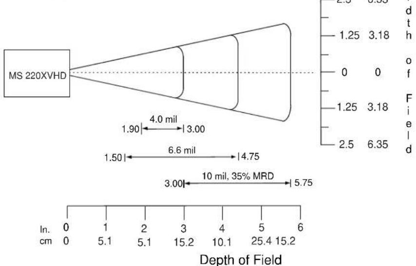
other
| Depth of Field | Distance (mil) | | -------------- | -------------- | | 4.75 | 6.6 | | 5.75 | 10 |Figure 7-6 Symbol MS2207VHD 2D Slab/Raster Decode Distances

NOTE Not optimized for omnidirectional mode.
Symbol MS2207VHD 2D Decode Distances
Table 7-4 Symbol MS2207VHD 2D Slab/Raster Decode Distances
| Symbol Density/p/n / Bar Code Type | Bar Code Content/Contrast1 | Typical Working Ranges3 | Guaranteed Working Ranges3 | ||
| Near Far | Near Far | ||||
| 4 mil64-17025-01PDF417 | 12380% MRD | 1.90 in.4.83 cm | 3.00 in.7.62 cm | 2.20 in.5.59 cm | 2.70 in.6.89 cm |
| 6.6 mil64-14035-01PDF417 | ABCDEF80% MRD | 1.50 in.3.81 cm | 4.75 in.12.07 cm | 2.00 in.5.08 cm | 4.50 in.11.43 cm |
| 10 mil64-14937-01PDF417 | 01234567890580% MRD | 3.00 in.7.62 cm | 5.75 in.14.61 cm | 4.25 in.10.80 cm | 5.00 in.12.72 cm |
Notes:
-
Contrast measured as Mean Reflective Difference (MRD) at 650 nm.
-
Near ranges on lower densities largely depend on the width of the bar code and the scan angle.
-
Working range specifications: Photographic quality symbols, pitch = 10°, skew = 0°, roll = 0°, ambient light < 150 ft. candles, and temperature = 23 °C.

NOTE Not optimized for omnidirectional mode.
Usable Scan Length
The decode zone is a function of various symbol characteristics including density, print contrast, wide-to-narrow ratio, and edge acuity. Consider width of decode zone at any given distance when designing a system.
Calculating the Usable Scan Length Method on page 2-8 describes how to calculate the usable scan length. The scan angle is provided in the Usable Scan Length Diagram on page 2-8.
7 - 12 Symbol MiniScan MSXX07 Series Integration Guide
Chapter 8 Symbol MS3207 Specifications
Introduction
This chapter provides the technical specifications for the Symbol MS3207 scanner.
Symbol MS3207 Electrical Interface
This section describes the pin functions of the Symbol MS3207 interface.

natural_image
Front view of a 16-pin electronic connector (no text or symbols visible)Figure 8-1 Symbol MS3207 Connector
Table 8-1 Symbol MS3207 Electrical Interface
| Pin No. | Pin Name Type* | Function | |
| 1 Trigger I | Signals to scanner to | begin scanning session. | |
| 2 TXD O | Serial data transmit output. | Drives the serial data receive input on the device communicating with the scanner. | |
| 3 RXD/D+ | I/O RS-232 Mode: Serial data receive input. Driven by the serial data transmit output on the device communicating with the scanner. | ||
| 4 SYN_CLK | I/O Synapse Mode: Synapse | Clock line. Signal used as a clock by a Synapse host. Pin is shorted to RTS/SYN_DAT in USB cables to allow for auto-detection of USB mode via signal loopback. | |
| 5 Ground | Power supply ground input and signal ground reference. | ||
| 6 Power 5 | 0 VDC ± 10% | ||
| *I = Input O = Output | |||
Table 8-1 Symbol MS3207 Electrical Interface (Continued)
| Pin No. | Pin Name Type* Function | |
| 7 CTS/D- | I/O RS-232 Mode: Clear-to-send | handshaking input line, used only in conjunction with the RTS line. Optionally used by another device to signal the scanner to begin transmitting data.USB Mode: D- signal. During USB operation this signal works in conjunction with the D+ signal as a differential bi-directional signal. |
| 8 RTS/SYN_DAT | I/O RS-232 Mode: Request-to-send handshaking output line, used only in conjunction with the CTS line. Optionally used by the scanner to signal another device that data is available to send.Synapse Mode: Synapse Data line. Signal is used to transmit data to and from a Synapse host. | |
| 9 Beeper/Download I/O During normal operation this signal functions as an external beeper drive line. This signal can sink 50mA of current to drive an external beeper, and is normally pulled up. This signal is also used to begin Flash Download operation when grounded externally during power up. | ||
| *I = Input O = Output | ||
Symbol MS3207 Mechanical Drawings
![DB9 CONNECTOR FRONT OF SCAN ENGINE NOMINAL SCAN AXIS .08 TYP COLLECTION FIELD 1.86 [47] .67 [17] .80 [20] 1.37 [35] 3.43 [87] 1.50 MIN. [38] 1.13 [29] 43.0° NOMINAL SCAN ANGLE 34.0° VERTICAL SCANNING FIELD 100× UPC (OMNI MODE)](/content/2026/05/1068115/images/d6e3a5cd63f7d7d6c07be56d3c466f465d8189f4108342c3e3c487cfcfd96751.jpg)
Notes:
Unless otherwise specified:
- Dimensions are in inches, dimensions in [ ] are mm.
- User mounting tolerances are not included.
![2.29 [58]](/content/2026/05/1068115/images/e85a73de1794907e66a7fe4a0e1e2ee807b0785fcc2ca268351f83f5e09aa7d7.jpg)
Figure 8-2 Symbol MS3207 Mechanical Drawing
![44.0° HORIZONTAL SCANNING FIELD 34.0° .13 HORIZONTAL COLLECTION FIELD .10 HORIZONTAL COLLECTION FIELD NOMINAL SCAN ANGLE .76 [19] 1.82 [46] 1.37 [35] .56 [14] FRONT OF SCAN ENGINE (.40) [10] MFG. LABEL 3X M3 - 3.6 MM LG. MAX. MOUNTING SCREW HOLES 1.50 [38]](/content/2026/05/1068115/images/bb59c0f9ac5871447ab0dd0f2f007e52ffadfc7e4567d8f91b04aeb5746bbb81.jpg)
Notes:
Unless otherwise specified:
- Dimensions are in inches, dimensions in [ ] are mm.
- User mounting tolerances are not included.

natural_image
Line drawing of a conical device with a rectangular housing and mounting holes (no text or symbols)Figure 8-3 Symbol MS3207 Mechanical Drawing
Symbol MS3207 Technical Specifications
Table 8-2 Symbol MS3207 Technical Specifications @ 23°C
| Item Description | |
| Power Requirements | |
| Input Voltage | +5.0 VDC ± 10% |
| Scanning Current | 250 ± 30 mA typical |
| Standby Current | 45 ± 10 mA typical |
| Vcc Noise Level | 200 mV peak-to-peak max. |
| Laser Power 0.7 mW typical, 0.8 mW maximum @ 650 nm | |
| Scan Rate 640 scans/second | |
| Scan Frequency: Horizontal 320 Hz ± 5 Hz | |
| Scan Frequency: Vertical 282 Hz ± 5 Hz | |
| Frame Rate 24 frames/sec. 12 Hz ±1 Hz (vertical) | |
| Print Contrast Minimum 35% absolute dark/light reflectance differential (PDF);35% absolute dark/light reflectance differential (1-D) | |
| Scan Angle | Horizontal: 34irc ± 1.5irc Vertical: 34irc ± 1.5irc |
| Scan Pattern Omnidirectional, semi-omnidirectional, smart raster, high density single scan line | |
| Start Time 0.065 sec. to 75% of steady state horizontal amplitude | |
| Skew Tolerance | ± 15° from normal (see Figure 8-4 on page 8-8) |
| Pitch Angle | ± 30° from normal (see Figure 8-4 on page 8-8) |
| Roll | ± 4° from vertical (see Figure 8-4 on page 8-8)(For scanning benchmark label, assuming 3:1 codeword aspect ratio). Note that this is dependent on the decoder. |
| Decode Depth of Field See | Figure 8-5 on page 8-9 and Figure 8-6 on page 8-11 |
| Beam Deviation(offset from the nominal) | Horizontal: ±3.0°Vertical: ±3.0°Horizontal tilt: ± 2° |
| Additional Post Shock Beam Deviation (2000G Shock) | Horizontal: ±3.0° maxVertical: ±6.0° max |
| Ambient Light ImmunitySunlightArtificial Light | 8,000 ft. candles (86,112 lux)450 ft. candles (4,844 lux) |
| Item | Description |
| Drop 30 inch drop | |
| Vibration Unpowered scanner with | stands a random vibration along each of the X, Y and Z axes for a period of one hour per axis, defined as follows:20 to 80 Hz Ramp up to 0.04 G^2/Hz at the rate of 3dB/octave.80 to 350 Hz 0.04 G^2/Hz350 to 2000 Hz Ramp down at the rate of 3 dB/octave. |
| ESD ± 20kV air discharge | ± 8kV indirect discharge |
| Sealing IP54 | |
| Operating Temperature -22°F to 1 | 22°F (-30°C to 50°C) |
| Storage Temperature -40°F to 158°F (-40°C to 70°C) | |
| Humidity 5% to 95% non-condensing | |
| Laser Class CDRH Class II, IEC Class 2 | |
| Height 1.98 in. (5.03 cm) | |
| Width 2.41 in. (6.12 cm) | |
| Depth | 3.60 in. (9.14 cm) |
| Weight | 4.97 oz. (142 g) |
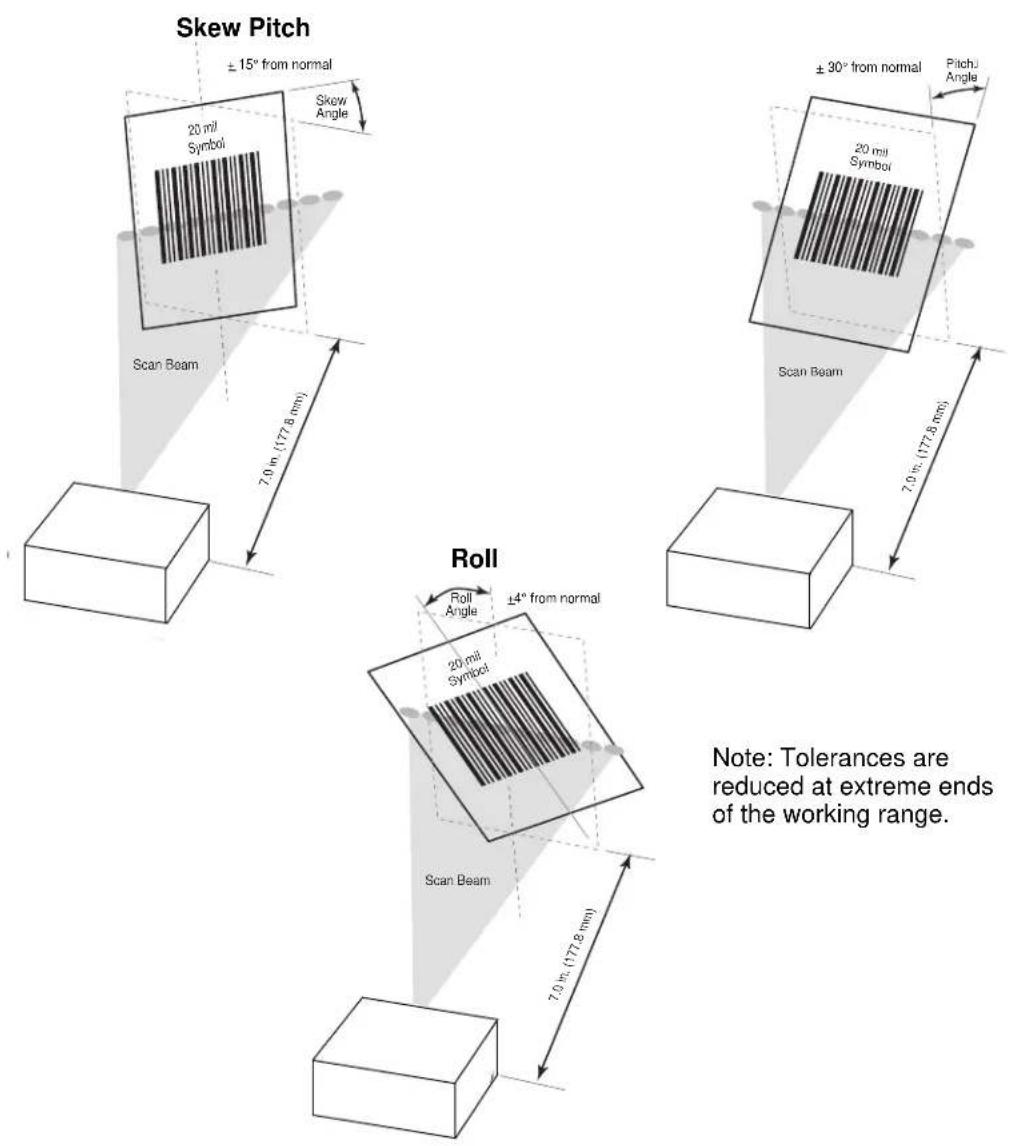
Note: Tolerances are reduced at extreme ends of the working range.
Figure 8-4 Skew, Pitch and Roll
Symbol MS3207 Decode Zones
The decode zone is a function of various symbol characteristics including density, print contrast, wide to narrow ratio and edge acuity. Typical values appear. Table 8-3 on page 8-10 and Table 8-4 on page 8-12 list the typical and guaranteed distances for selected bar code densities. The minimum element width (or "symbol density") is the width in mils of the narrowest element (bar or space) in the symbol. The maximum usable length of a symbol at any given range appears below. To calculate this distance, see Calculating the Usable Scan Length Method on page 2-8.
Symbol MS3207 Omnidirectional Decode Distances
Note: Typical performance at 68°F (20°C)
on high quality symbols in normal room light.
Vcc = 5V

1.00 | 80% UPC | 6.5


bar
| Depth of Field | Value | | -------------- | ----- | | In. | 0 | | cm | 0.127 | | | 0.254 | | | 0.381 | | | 0.508 | | | 0.751 | | | 1.0 | | | 12.5 | | | 63.5 |Depth of Field
* Minimum distance determined by symbol length and scan angle.
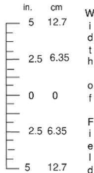
other
| Position | W | Value | |---|---|---| | Top Left | i | 5 | | Top Right | d | 12.7 | | Bottom Left | t | 2.5 | | Bottom Right | h | 6.35 | | Bottom Center | o | 0 | | Bottom Center | f | 0 | | Bottom Right | F | 2.5 | | Bottom Center | i | 6.35 | | Bottom Center | e | 2.5 | | Bottom Center | l | 5 | | Bottom Right | d | 12.7 | in. cmFigure 8-5 Symbol MS3207 Omnidirectional Decode Zone (Typical)
Table 8-3 Symbol MS3207 Omnidirectional Decode Distances
| Symbol Density/p/n / Bar Code Type | Bar Code Content/Contrast1 | Typical Working Ranges3 | Guaranteed Working Ranges3 | ||
| Near Far | Near Far | ||||
| 6.0 mil | 123 | 0.25 in. | 3.25 in. | 0.75 in. | 2.25 in. |
| 60-01755-01 | 80% MRD | 0.64 cm | 8.3 cm | 1.9 cm | 5.7 cm |
| Code 39 | |||||
| 64-06629-01 | 0080015 | 1.0 in. | 6.5 in. | 1.5 in. | 4.5 in. |
| 80% UPC | 85% MRD | 2.5 cm | 16.5 cm | 3.8 cm | 11.4 cm |
| 13 mil | 012345678905 | 1.5 in. | 12.5 in. | Note 2 9.5 in. | |
| 64-05303-01 | 80% MRD | 3.8 cm | 31.2 cm | 24.1 cm | |
| 100% UPC | |||||
| 20 mil 1D | 123 | 1.75 in. | 12.5 in. | Note 2 10.0 in. | |
| 60-02710-03 | 80% MRD | 4.4 cm | 31.8 cm | 25.4 cm | |
| LC 35% | |||||
Notes:
-
Contrast measured as Mean Reflective Difference (MRD) at 650 nm.
-
Near ranges on largely depend on the width of the bar code and the scan angle.
-
Working range specifications: Photographic quality symbols, pitch = 15°, skew = 0°, roll = 0°, ambient light < 150 ft. candles, and temperature = 23 °C, Vcc = 5V.
-
Measured from the front of the scanner.
Symbol MS3207 2D Slab/Raster Decode Distances

other
| Depth of Field | In. cm | Value | | -------------- | ------ | ----- | | 0 | 11 | 27.9 | | 5 | 10 | 25.4 | | 10 | 7.5 | 15.2 | | 15 | 5 | 10.1 | | 20 | 2.5 | 5.1 | | 25 | 0 | 0 | | 30 | 2.5 | 5.1 | | 35 | 5 | 10.1 | | | 7.5 | 15.2 | | | 10 | 25.4 | | | 11 | 27.9 | | | | | | | | | | | | | | | | | | | | | | | | | | | | | | | | | | | | | | | | | | | | | | | | | | | | | | | | | | | | | | | | | | | | | | | | | | | | | | | | | | | | | | | | | | | | | | | | | | | | | | | | | | | | | | | | | | | | | | | | | | | | | | | | | | | | | | | | | | | | | | | | | | | | | | | | | | | | | | | | | | | | | | | | | | | | | | | | 10 | 5.25 | | | 10 | 9.5 | | | 15 | 14.0 | | | | | | | | | | | | | | | | | | | | | | | | | | | | | | | | | | | | | | | | | | | | | | | | | | | | | | | | | | | | | | | | | | | | | | | | | | | | | | | | | | | | | | | | | | | | | | | | | | | | | | | | | | | | | | | | | | | | | | | | | | | | | | | | | | | | | | | | | | | | | | | | | | | | | | | | | | | | | | | | | | | | | | | | | | | | | | | | -10 | -10 | | | -10 | -10 | | | -10 | -10 | | | -10 | -10 | | | -10 | -10 | | | -10 | -10 | | | -10 | -10 | | | -10 | -10 | | | | -10 | -10 | | | -10 | -10 | | | -10 | -10 | | | -10 | -10 | | | -10 | -10 | | | -10 | -10 | | | -10 | -10 | | (Note: Minimum distance determined by symbol length and scan angle.)Figure 8-6 Symbol MS3207 2D Slab/Raster Decode Zone
Table 8-4 Symbol MS3207 2D Slab/Raster Decode Distances
| Symbol Density/p/n / Bar Code Type | Bar Code Content/Contrast1 | Typical Working Ranges3 | Guaranteed Working Ranges3 | ||
| Near Far | Near Far | ||||
| 6.6 mil64-14035-012D | 12380% MRD | 1.0 in.2.54 cm | 5.25 in.13.34 cm | 1.5 in.3.8 cm | 3.75 in.9.5 cm |
| 10 mil64-14037-012D | ABCDEF80% MRD | 3.5 in.8.89 cm | 9.5 in.24.13 cm | 5.0 in.12.7 cm | 7.5 in.9.5 cm |
| 15 mil64-14038-012D | 01234567890580% MRD | 6.5 in.16.51 cm | 14.0 in.35.6 cm | Note 2 11.0 in. | 24.1 cm |
| 55 mil64-17458-011D | CD80% MRD | 1.0 in.2.54 cm | 32 in.81.3 cm | Note 2 22.0 in. | 55.9 cm |
Notes:
-
Contrast measured as Mean Reflective Difference (MRD) at 650 nm.
-
Near ranges on largely depend on the width of the bar code and the scan angle
-
Working range specifications: Photographic quality symbols, pitch = 15°, skew = 0°, roll = 0°, ambient light < 150 ft. candles, and temperature = 23 °C, Vcc = 5V.
-
Measured from the front of the scanner.
Usable Scan Length
The decode zone is a function of various symbol characteristics including density, print contrast, wide-to-narrow ratio, and edge acuity. Width of decode zone at any given distance must be considered when designing a system.
Calculating the Usable Scan Length Method on page 2-8 provides a detailed description of how to calculate the usable scan length. The scan angle is provided in Table 8-2 on page 8-6.
Chapter 9 Maintenance and Troubleshooting
Introduction
The chapter provides information on maintenance and troubleshooting.
Maintenance
Cleaning the exit window is the only maintenance required. Do not allow any abrasive material to touch the window. Clean the scan window with a damp cloth and, if necessary, a non-ammonia based detergent.
Troubleshooting
Table 9-1 Troubleshooting
| Problem Possible Cause Possible Solutions | ||
| No red LED or nothing happens during a scan attempt. | No power to the scanner. Check the system power. Confirm that the correct host interface cable is used. | |
| Scanner cannot read the bar code. | Interface/power cables are loose. | Re-connect loose cables. |
| Scanner is not programmed for the correct bar code type. | Make sure the scanner is programmed to read the type of bar code to be scanned. Scan other bar code(s) and bar code types. | |
| Incorrect communication parameters. | Set the correct communication parameters (baud rate, parity, stop bits, etc.) | |
| Bar code symbol is unreadable. | Check the symbol to make sure it is not defaced. Try scanning similar symbols of the same code type. | |
| Inappropriately hot environment. | Remove the scanner from the hot environment, and allow it to cool down. | |
| Laser activates, followed by a beep sequence. | Beeper is configured. See | Table 3-1 on page 3-7for beeper indication descriptions. |
| Scanner does not function. | Accidentally scanned Level Trigger or Pulse Trigger from Trigger Options on page 3-5. | Cycle power to the scanner. As the laser briefly appears after power up, scan the Continuous bar code from Trigger Options on page 3-5. |
| Connect an interface cable which has an external trigger jack, a push button trigger cable, and a power supply to the scanner. You can purchase these cables from Motorola, or make a similar one using the scanner's pinouts as a reference. See the specification chapter for your MiniScan model for pinouts. Using a momentary switch, short the scanner's trigger line to ground to activate the laser, then scan the Continuous option of the Trigger Mode parameter. | ||

NOTE If after performing these checks the symbol still does not scan, contact the distributor or Motorola Enterprise Mobility Support. See page xv for contact information.
Chapter 10 Parameter Menus
Introduction
This chapter describes the programmable parameters, and provides bar codes for programming.
Throughout the programming bar code menus, asterisks (*) indicate default values.
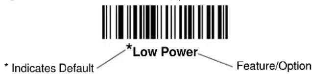
Operational Parameters
MiniScan scanners ship with the default settings in Table 10-1 on page 10-2. These default values are stored in non-volatile memory and are preserved even when the scanner is powered down.
To change the default values, scan the appropriate bar codes in this chapter. These new values replace the standard default values in memory. To reset the default parameter values, scan the Set All Defaults bar code on page 10-7.
Default Table
Table 10-1 lists the defaults for all parameters, and the page number each parameter appears on. To change any option, scan the appropriate bar code(s).
Table 10-1 Default Table
| Parameter Default | Page Number | |
| Set Default Parameter All Defaults | 10-7 | |
| Scanning Options | ||
| Beeper Volume High Volume | 10-8 | |
| Beeper Tone High Frequency | MS1207WA only: Medium Frequency | 10-9 |
| Beeper Frequency Adjustment 2500 Hz | 10-9 | |
| Laser On Time MS120X: 3.0 sec | MS220X/3207: 5.0 sec | 10-10 |
| Scan Angle (Symbol MS1207FZY only) Wide | 10-10 | |
| Power Mode Low Power | 10-11 | |
| Trigger Mode Continuous | 10-11 | |
| Scanning Mode (Symbol MS2207, MS2207VHD, and MS3207 only) | MS2207/2207VHD: Smart RasterMS3207: Omnidirectional | 10-12 |
| Aiming Mode Disabled | 10-13 | |
| Raster Height (Symbol MS2207, MS2207VHD, and MS3207 only) | 15 | 10-14 |
| Raster Expansion Rate(Symbol MS2207, MS2207VHD, and MS3207 only) | 11 | 10-14 |
| Time-out Between Same Symbol 0.6 sec | 10-15 | |
| Time-out Between Different Symbols 0.0 sec | 10-15 | |
| Beep After Good Decode | Enable | 10-16 |
| Transmit “No Read” Message | Disable | 10-16 |
| Parameter Scanning | Enable | 10-17 |
| Linear Code Type Security Levels | MS120X: 1MS220X/MS3207: 2 | 10-18 |
| Bi-directional Redundancy | Disable | 10-19 |
| UPC/EAN | ||
| UPC-A | Enable | 10-20 |
| UPC-E | Enable | 10-20 |
| Parameter | Default | Page Number |
| UPC-E1 Disable | 10-21 | |
| EAN-8 Enable | 10-21 | |
| EAN-13 Enable | 10-22 | |
| Bookland EAN Disable | 10-22 | |
| UPC/EAN Coupon Code Disable | 10-23 | |
| Decode UPC/EAN Supplementals Ignore | 10-24 | |
| User-Programmable Supplementals | 10-28 | |
| Decode UPC/EAN Supplemental Redundancy MS1207FZY: 14MS1207WA: 7MS2207/3207: 12 | 10-28 | |
| Transmit UPC-A Check Digit Enable | 10-29 | |
| Transmit UPC-E Check Digit Enable | 10-29 | |
| Transmit UPC-E1 Check Digit Enable | 10-30 | |
| UPC-A Preamble System Character | 10-31 | |
| UPC-E Preamble System Character | 10-32 | |
| UPC-E1 Preamble System Character | 10-33 | |
| Convert UPC-E to A Disable | 10-34 | |
| Convert UPC-E1 to A | Disable | 10-34 |
| EAN-8 Zero Extend | Disable | 10-35 |
| Bookland ISBN Format | ISBN-10 | 10-36 |
| UPC/EAN Security Level | 0 | 10-37 |
| Linear UPC/EAN Decode | Disable | 10-38 |
| UPC Half Block Stitching(Symbol MS2207, MS2207VHD, and MS3207 only) | Disable | 10-38 |
Code 128
| Code 128 | Enable | 10-39 |
| UCC/EAN-128 Enable | 10-39 | |
| ISBT 128 | MS120X: EnableMS220X/MS3207: Disable | 10-40 |
| Code 128 Decode Performance(Symbol MS2207, MS2207VHD, and MS3207 only) | Enable | 10-41 |
| Parameter | Default | Page Number |
| Code 128 Decode Performance Level(Symbol MS2207, MS2207VHD, and MS3207 only) | Level 3 | 10-42 |
| Code 39 | ||
| Code 39 Enable | 10-43 | |
| Trioptic Code 39 Disable | 10-43 | |
| Convert Code 39 to Code 32 Disable | 10-44 | |
| Code 32 Prefix Enable | 10-44 | |
| Set Length(s) for Code 39 Length within Range: MS120X: 2-55MS220X/MS3207: 1-55 | 10-45 | |
| Code 39 Check Digit Verification Disable | 10-46 | |
| Transmit Code 39 Check Digit Disable | 10-46 | |
| Code 39 Full ASCII Conversion Disable | 10-47 | |
| Code 39 Decode Performance(Symbol MS2207, MS2207VHD, and MS3207 only) | Enable | 10-48 |
| Code 39 Decode Performance Level(Symbol MS2207, MS2207VHD, and MS3207 only) | Level 3 | 10-49 |
| Code 93 | ||
| Code 93 Disable | 10-50 | |
| Set Length(s) for Code 93 Length within Range: 04-55 | 10-51 | |
| Code 11 | ||
| Code 11 Disable | 10-52 | |
| Set Length(s) for Code 11 Length within Range: 04-55 | 10-53 | |
| Code 11 Check Digit Verification Disable | 10-54 | |
| Transmit Code 11 Check Digits Disable | 10-55 | |
| Interleaved 2 of 5 | ||
| Interleaved 2 of 5 | MS120X: EnableMS220X/MS3207: Disable | 10-56 |
| Set Length(s) for I 2 of 5 | 1 Discrete Length: 14 | 10-57 |
| I 2 of 5 Check Digit Verification | Disable | 10-58 |
| Transmit I 2 of 5 Check Digit | Disable | 10-59 |
| Convert I 2 of 5 to EAN 13 | Disable | 10-59 |
| Discrete 2 of 5 | ||
| Discrete 2 of 5 Disable | 10-60 | |
| Set Length(s) for D 2 of 5 1 Discrete Length: 12 | 10-61 | |
| Codabar | ||
| Codabar Disable | 10-62 | |
| Set Lengths for Codabar Length within Range: 05-55 | 10-63 | |
| CLSI Editing Disable | 10-64 | |
| NOTIS Editing Disable | 10-64 | |
| MSI Plessey | ||
| MSI Plessey Disable | 10-65 | |
| Set Length(s) for MSI Plessey Length Within Range: | MS1207WA only: 01 - 55All other versions: 06 - 55 | 10-66 |
| MSI Plessey Check Digits One | 10-67 | |
| Transmit MSI Plessey Check Digit Disable | 10-67 | |
| MSI Plessey Check Digit Algorithm Mod 10/Mod 10 | 10-68 | |
| PDF417/MicroPDF417 (Symbol MS2207, MS2207VHD, and MS3207 Only) | ||
| PDF417 | MS220X:MS3207: Disable | 10-69 |
| MicroPDF417 Disable | 10-69 | |
| MicroPDF Performance Standard | 10-70 | |
| Code 128 Emulation | Disable | 10-71 |
| GS1 DataBar | ||
| GS1 DataBar-14 | Disable | 10-72 |
| GS1 DataBar Limited | Disable | 10-72 |
| GS1 DataBar Expanded | Disable | 10-73 |
| Convert GS1 DataBar to UPC/EAN(Symbol MS1207FZY, MS1207WA only) | Disable | 10-73 |
| Composite (Symbol MS2207, MS2207VHD and MS3207 only) | ||
| CC-C | Disable | 10-74 |
| CC-AB | Disable | 10-74 |
Enable
Table 10-1 Default Table (Continued)
| Parameter | Default | Page Number |
| TLC-39 Disable | 10-75 | |
| UPC Composite Mode Always Linked | 10-76 | |
| Data Options | ||
| Transmit Code ID Character None | 10-77 | |
| Prefix/Suffix Values | 10-79 | |
| Prefix | NULL | |
| Suffix 1 | CR | |
| Suffix 2 | LF | |
| Scan Data Transmission Format Data as is | 10-80 | |
| Event Reporting | ||
| Decode Event Disable | 10-83 | |
| Boot Up Event Disable | 10-83 | |
| Parameter Event Disable | 10-84 | |
| Macro PDF (Symbol MS2207, MS2207VHD, and MS3207 only) | ||
| Transmit Symbols in Codeword Format Disable | 10-85 | |
| Transmit Unknown Codewords Disable | 10-86 | |
| Escape Character None | 10-86 | |
| ECI (Symbol MS2207, MS2207VHD, and MS3207 only) | ||
| Delete Character Set ECIs Enable | 10-87 | |
| ECI Decoder Enable | 10-87 | |
| Transmit Macro PDF User-Selected Field (Symbol MS2207, MS2207VHD, and MS3207 only) | ||
| Transmit File Name | Disable | 10-88 |
| Transmit Block Count | Disable | 10-89 |
| Transmit Time Stamp | Disable | 10-89 |
| Transmit Sender | Disable | 10-90 |
| Transmit Addressee | Disable | 10-90 |
| Transmit Checksum | Disable | 10-91 |
| Transmit File Size | Disable | 10-91 |
| Transmit Macro PDF Control Header | Disable | 10-92 |
| Last Block Marker Disable | 10-92 | |
Set Default Parameter
Scan this bar code to return all parameters to the values listed in Table 10-1 on page 10-2.

Set All Defaults
Scanning Options
Beeper Volume
To select a decode beep volume, scan the Low Volume, Medium Volume, or High Volume bar code.

Low Volume
Medium Volume

*High Volume
Beeper Tone
To select a decode beep frequency (tone), scan the appropriate bar code.
Low Frequency

Medium Frequency

*High Frequency
Beeper Frequency Adjustment
This parameter adjusts the frequency of the high beeper tone from the nominal 2500 Hz to another frequency matching the resonances of the installation. Program this in 10 Hz increments from 1220 Hz to 3770 Hz.
To increase the frequency, scan the bar code below, then scan three numeric bar codes beginning on page 10-93 that correspond to the desired frequency adjustment divided by 10. For example, to set the frequency to 3000 Hz (an increase of 500 Hz), scan numeric bar codes 0, 5, 0, corresponding to 50, or (500/10).
To decrease the frequency, scan the bar code below, then scan three numeric bar codes beginning on page 10-93 that correspond to the value (256 - desired adjustment/10). For example, to set the frequency to 2000 Hz (a decrease of 500 Hz), scan numeric bar codes 2, 0, 6, corresponding to 206, or (256 - 500/10).
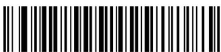
Beeper Frequency Adjustment
(Default: 2500 Hz)
Laser On Time
This parameter sets the maximum time decode processing continues during a scan attempt. It is programmable in 0.1 second increments from 0.5 to 9.9 seconds.
To set a Laser On Time, scan the bar code below. Next scan two numeric bar codes beginning on page 10-93 that correspond to the desired on time. Include a leading zero for times less than 1.0 second. For example, to set an on time of 0.5 seconds, scan the bar code below, then scan the 0 and 5 bar codes. To change the selection or to cancel an incorrect entry, scan the Cancel bar code on page 10-95.

Laser On Time
Scan Angle

NOTE This option is supported by the Symbol MS1207FZY only.
This parameter sets the scan angle to the default or alternate angle.
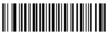
*Default Angle

Alternate Angle
Power Mode
This parameter determines whether or not power remains on after a decode attempt. In Low Power mode, the scanner enters into a low power consumption mode when possible, provided all WAKEUP signals are released. In Continuous On mode, power remains on after each decode attempt.

Continuous On

*Low Power
Trigger Mode
- Level - A trigger pull activates the laser and decode processing. The laser remains on and decode processing continues until a trigger release, a valid decode, or the Laser On Time-out is reached.
- Pulse - A trigger pull activates the laser and decode processing. The laser remains on and decode processing continues until a valid decode or the Laser On Time-out is reached.
- Continuous - The laser is always on and decoding.
- Blink - This trigger mode is used for triggerless ScanStand operation. Scanning range is reduced in this mode. This mode is only supported by Symbol MS1207FZY models.
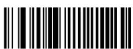
Level

Pulse

*Continuous
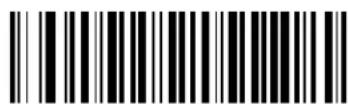
Blink
Scanning Mode

NOTE These options are supported by the Symbol MS2207, MS2207VHD, and MS3207 only.
Select one of the following scanning modes:
• Smart Raster • Always Raster
- Slab Only Raster • Programmable Raster
- Omnidirectional (Cyclone) • Semi-Omnidirectional

NOTE If you select Omnidirectional, Motorola recommends disabling the following parameters: PDF417, MicroPDF417, DataBar Limited, CC-C, CC-AB, TLC-39 and Linear UPC.

* Smart Raster

Always Raster

Programmable Raster
Slab Pattern

Omnidirectional Pattern

Semi-Omni Pattern
Aiming Mode
For handheld mode only, select an aiming dot to appear for a normal or extended period of time.

*No Aiming Dot
Aiming Dot
Normal (200 ms) Timeout

Aiming Dot
Extended (400 ms) Timeout
Programmable Raster Height and Raster Expansion Speed

NOTE Only the Symbol MS2207, MS2207VHD, and MS3207 support these options.
If you enabled Programmable Raster or Always Raster, this parameter selects the laser pattern's height and rate of expansion. This parameter is intended for very specific applications, and is usually not necessary.
To select the laser pattern's height and/or rate of expansion:
- Scan the bar code for either Raster Height or Raster Expansion Speed below.
- Scan two numeric bar codes beginning on page 10-93 that represent a two-digit value. Valid values are between 01 and 15.
To change the selection or to cancel an incorrect entry, scan the Cancel bar code on page 10-95.

Raster Height (Default 15)
Raster Expansion Speed (Default 11)
Timeout Between Decodes
Timeout Between Decodes, Same Symbol
When in Continuous triggering mode, this parameter sets the minimum duration of not decoding data before the scanner decodes a second bar code identical to one just decoded. This reduces the risk of accidentally scanning the same symbol twice. It is programmable in 0.1 second increments from 0.0 to 9.9 seconds. The recommended interval is 0.6 seconds
Timeout Between Decodes, Different Symbol
This option sets the minimum duration of not decoding data before the scanner decodes a second (different) bar code. Use this in Continuous mode to prevent the scanner from decoding when a different symbol appears in the scanner's field of view before the timeout period between decodes expires. This is programmable in 0.1 second increments from 0.0 to 9.9 seconds. The recommended value is 0.0 seconds.
Select the timeout between decodes for the same or different symbols.
- Scan the option bar code to set.
- Scan two numeric bar codes beginning on page 10-93 which correspond to the desired interval, in 0.1 second increments.
To change the selection or to cancel an incorrect entry, scan the Cancel bar code on page 10-95.
Timeout Between Decodes - Same Symbol

Timeout Between Decodes - Different Symbols
Beep After Good Decode
Scan this symbol to set the scanner to beep after a good decode.
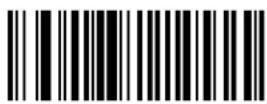
*Beep After Good Decode
Scan this symbol to set the scanner not to beep after a good decode. The beeper still operates during parameter menu scanning and indicates error conditions.

Do Not Beep After Good Decode
Transmit "No Read" Message
Enable this option to transmit "NR" if a 1-D symbol does not decode, and "FR" if a 2-D symbol does not decode. Any enabled prefix or suffixes are appended around this message.
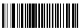
Enable No Read
If you disable this parameter, and a symbol can not be decoded, no message is sent to the host.

*Disable No Read
Parameter Scanning
To disable the decoding of parameter bar codes, scan the bar code below. The scanner can still decode the Set Defaults parameter bar code. To enable decoding of parameter bar codes, either scan *Enable Parameter Scanning or Set All Defaults.

*Enable Parameter Scanning

Disable Parameter Scanning
Linear Code Type Security Level

NOTE Does not apply to Code 128.
MiniScan scanners offer four levels of decode security for linear code types (e.g., Code 39, Interleaved 2 of 5). Select higher security levels for decreasing levels of bar code quality. As security levels increase, the scanner's aggressiveness decreases.
Select the security level appropriate for bar code quality.
Linear Security Level 1
The following code types must be successfully read twice before being decoded:
| Code Type Length | |
| Codabar All | |
| MSI Plessey 4 or less | |
| D 2 of 5 8 or less | |
| I 2 of 5 8 or less |
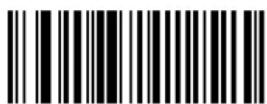
Linear Security Level 1
Linear Security Level 2
All code types must be successfully read twice before being decoded.
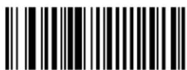
*Linear Security Level 2
Linear Security Level 3
Code types other than the following must be successfully read twice before being decoded. The following codes must be read three times:
| Code Type Length | |
| MSI Plessey 4 or less | |
| D 2 of 5 8 or less | |
| I 2 of 5 8 or less |
Linear Security Level 3
Linear Security Level 4
All code types must be successfully read three times before being decoded.

Linear Security Level 4
Bi-directional Redundancy
This parameter is only valid if you enabled a Linear Code Type Security Level on page 10-18. When this parameter is enabled, a bar code must be successfully scanned in both directions (forward and reverse) before being decoded.
Enable Bi-directional Redundancy

*Disable Bi-directional Redundancy
UPC/EAN
Enable/Disable UPC-A
To enable or disable UPC-A, scan the appropriate bar code below.
*Enable UPC-A
Disable UPC-A
Enable/Disable UPC-E
To enable or disable UPC-E, scan the appropriate bar code below.

*Enable UPC-E

Disable UPC-E
Enable/Disable EAN-13
To enable or disable EAN-13, scan the appropriate bar code below.

*Enable EAN-13

Disable EAN-13
Enable/Disable Bookland EAN
To enable or disable EAN Bookland, scan the appropriate bar code below.

Enable Bookland EAN
*Disable Bookland EAN

NOTE If you enable Bookland EAN, select a Bookland ISBN Format on page 10-36. Also select either Decode UPC/EAN Supplementals, Autodiscriminate UPC/EAN Supplementals, or Enable 978/979 Supplemental Mode in Decode UPC/EAN Supplementals on page 10-24.
UPC/EAN Coupon Code
Enable this to decode UPC-A bar codes starting with digit '5', EAN-13 bar codes starting with digit '99', and UPC-A/EAN-128 Coupon Codes. You must enable UPC-A, EAN-13 and EAN-128 to scan all types of Coupon Codes.

Enable UPC/EAN
Coupon Code
*Disable UPC/EAN Coupon Code

NOTE Use the Decode UPC/EAN Supplemental Redundancy on page 10-28 parameter to control autodiscrimination of the EAN-128 (right half) of a coupon code.
Decode UPC/EAN Supplementals
Supplementals are bar codes appended according to specific format conventions (e.g., UPC A+2, UPC E+2, EAN 13+2). The following options are available:
- If you select Ignore UPC/EAN with Supplementals, and the scanner is presented with a UPC/EAN plus supplemental symbol, the scanner decodes UPC/EAN and ignores the supplemental characters.
- If you select Decode UPC/EAN with Supplementals, the scanner only decodes UPC/EAN symbols with supplemental characters, and ignores symbols without supplementals.
- If you select Autodiscriminate UPC/EAN Supplementals, the scanner decodes UPC/EAN symbols with supplemental characters immediately. If the symbol does not have a supplemental, the scanner must decode the bar code the number of times set via Decode UPC/EAN Supplemental Redundancy on page 10-28 before transmitting its data to confirm that there is no supplemental.
- If you select one of the following Supplemental Mode options, the scanner immediately transmits EAN-13 bar codes starting with that prefix that have supplemental characters. If the symbol does not have a supplemental, the scanner must decode the bar code the number of times set via Decode UPC/EAN Supplemental Redundancy on page 10-28 before transmitting its data to confirm that there is no supplemental. The scanner transmits UPC/EAN bar codes that do not have that prefix immediately.
- Enable 378/379 Supplemental Mode
- Enable 978/979 Supplemental Mode

NOTE If you select 978/979 Supplemental Mode and are scanning Bookland EAN bar codes, see Enable/Disable Bookland EAN on page 10-22 to enable Bookland EAN, and select a format using Bookland ISBN Format on page 10-36.
- Enable 977 Supplemental Mode
- Enable 414/419/434/439 Supplemental Mode
- Enable 491 Supplemental Mode
- Enable Smart Supplemental Mode - applies to EAN-13 bar codes starting with any prefix listed previously.
- Supplemental User-Programmable Type 1 - applies to EAN-13 bar codes starting with a 3-digit user-defined prefix. Set this 3-digit prefix using User-Programmable Supplementals on page 10-28.
- Supplemental User-Programmable Type 1 and 2 - applies to EAN-13 bar codes starting with either of two 3-digit user-defined prefixes. Set the 3-digit prefixes using User-Programmable Supplementals on page 10-28.
- Smart Supplemental Plus User-Programmable 1 - applies to EAN-13 bar codes starting with any prefix listed previously or the user-defined prefix set using User-Programmable Supplementals on page 10-28.
- Smart Supplemental Plus User-Programmable 1 and 2 - applies to EAN-13 bar codes starting with any prefix listed previously or one of the two user-defined prefixes set using User-Programmable Supplementals on page 10-28.

NOTE To minimize the risk of invalid data transmission, select either to decode or ignore supplemental characters.
Decode UPC/EAN Supplementals (continued)
Select the desired option by scanning one of the following bar codes.

Decode UPC/EAN With Supplementals

*Ignore UPC/EAN Supplementals

Autodiscriminate UPC/EAN Supplementals

Enable 378/379 Supplemental Mode

Enable 978/979 Supplemental Mode
Decode UPC/EAN Supplementals (continued)
Enable 977 Supplemental Mode

Enable 414/419/434/439 Supplemental Mode
Enable 491 Supplemental Mode

Enable Smart Supplemental Mode
Decode UPC/EAN Supplementals (continued)
Supplemental User-Programmable Type 1

Supplemental User-Programmable Type 1 and 2

Smart Supplemental Plus User-Programmable 1

Smart Supplemental Plus User-Programmable 1 and 2
User-Programmable Supplementals
If you selected a Supplemental User-Programmable option from Decode UPC/EAN Supplementals on page 10-24, select User-Programmable Supplemental 1 to set the 3-digit prefix. Then select the 3 digits using the numeric bar codes beginning on page 10-93. Select User-Programmable Supplemental 2 to set a second 3-digit prefix. Then select the 3 digits using the numeric bar codes beginning on page 10-93.

User-Programmable Supplemental 1

User-Programmable Supplemental 2
Decode UPC/EAN Supplemental Redundancy
With Autodiscriminate UPC/EAN Supplementals selected, this option adjusts the number of times (from 2 to 30) to decode a symbol without supplementals before transmission. Motorola recommends five or above when decoding a mix of UPC/EAN symbols with and without supplementals.
Scan the bar code below to select a decode redundancy value. Next scan two numeric bar codes beginning on page 10-93. Enter a leading zero for single digit numbers. To change the selection or to cancel an incorrect entry, scan the Cancel bar code on page 10-95.

Decode UPC/EAN
Supplemental Redundancy
Transmit UPC-A Check Digit
Scan the appropriate bar code below to transmit the symbol with or without the UPC-A check digit.

*Transmit UPC-A Check Digit

Do Not Transmit UPC-A Check Digit
Transmit UPC-E Check Digit
Scan the appropriate bar code below to transmit the symbol with or without the UPC-E check digit.

*Transmit UPC-E Check Digit

Do Not Transmit UPC-E Check Digit
Transmit UPC-E1 Check Digit
Scan the appropriate bar code below to transmit the symbol with or without the UPC-E1 check digit.

*Transmit UPC-E1 CHECK DIGIT

Do Not Transmit UPC-E1 Check Digit
UPC-A Preamble
Select one of the following options to transmit a UPC-A preamble (Country Code and System Character) to the host device: transmit system character only, transmit system character and country code ("0" for USA), or transmit no preamble.
No Preamble ()

*System Character (

System Character & Country Code (
UPC-E Preamble
Select one of the following options to transmit a UPC-E preamble (Country Code and System Character) to the host device: transmit system character only, transmit system character and country code ("0" for USA), or transmit no preamble.

No Preamble ()

*System Character (

System Character & Country Code (
UPC-E1 Preamble
Select one of the following options to transmit a UPC-E1 preamble (Country Code and System Character) to the host device: transmit system character only, transmit system character and country code ("0" for USA), or transmit no preamble.

No Preamble ()
*System Character (

System Character & Country Code (
Convert UPC-E to UPC-A
This parameter converts UPC-E (zero suppressed) decoded data to UPC-A format before transmission. After conversion, data follows UPC-A format and is affected by UPC-A programming selections (e.g., Preamble, Check Digit).
Scan Do Not Convert UPC-E To UPC-A to transmit UPC-E (zero suppressed) decoded data.
Convert UPC-E To UPC-A (Enable)

*Do Not Convert UPC-E To UPC-A (Disable)
Convert UPC-E1 to UPC-A
Enable this parameter to convert UPC-E1 (zero suppressed) decoded data to UPC-A format before transmission. After conversion, data follows UPC-A format and is affected by UPC-A programming selections (e.g., Preamble, Check Digit).
Scan Do Not Convert UPC-E To UPC-A to transmit UPC-E1 (zero suppressed) decoded data.

Convert UPC-E1 To UPC-A (Enable)

*Do Not Convert UPC-E1 To UPC-A (Disable)
EAN Zero Extend
Enable this to add five leading zeros to decoded EAN-8 symbols to make them compatible in format to EAN-13 symbols.
Disable this parameter to transmit EAN-8 symbols as is.
Enable EAN Zero Extend

*Disable EAN Zero Extend
Bookland ISBN Format
If you enabled Bookland EAN using Enable/Disable Bookland EAN on page 10-22, select one of the following formats for Bookland data:
- Bookland ISBN-10 - The scanner reports Bookland data starting with 978 in traditional 10-digit format with the special Bookland check digit for backward-compatibility. Data starting with 979 is not considered Bookland in this mode.
- Bookland ISBN-13 - The scanner reports Bookland data (starting with either 978 or 979) as EAN-13 in 13-digit format to meet the 2007 ISBN-13 protocol.

*Bookland ISBN-10
Bookland ISBN-13

NOTE For Bookland EAN to function properly, first enable Bookland EAN using Enable/Disable Bookland EAN on page 10-22, then select either Decode UPC/EAN Supplementals, Autodiscriminate UPC/EAN Supplementals, or Enable 978/979 Supplemental Mode in Decode UPC/EAN Supplementals on page 10-24.
UPC/EAN Security Level
MiniScan scanners offer four levels of decode security for UPC/EAN bar codes. Select higher levels of security for decreasing levels of bar code quality. Increasing security decreases the scanner's aggressiveness, so choose only that level of security necessary for the application.
UPC/EAN Security Level 0
This default setting allows the scanner to operate in its most aggressive state, while providing sufficient security in decoding “in-spec” UPC/EAN bar codes.

*UPC/EAN Security Level 0
UPC/EAN Security Level 1
Select this option if misdecodes occur. This security level eliminates most misdecodes.
UPC/EAN Security Level 1
UPC/EAN Security Level 2
Select this option if Security level 1 fails to eliminate misdecodes.

UPC/EAN Security Level 2
UPC/EAN Security Level 3
If misdecodes still occur after selecting Security Level 2, select this security level. Be advised, selecting this option is an extreme measure against misdecoding severely out of spec bar codes. Selecting this level of security significantly impairs the scanner's decoding ability. If you need this level of security, try to improve the quality of the bar codes.

UPC/EAN Security Level 3
Linear UPC/EAN Decode
This option applies to code types containing two adjacent blocks (e.g., UPC-A, EAN-8, EAN-13). When enabled, a bar code transmits only when one laser scan successfully decodes both the left and right blocks. Enable this option when bar codes are in proximity to each other.

Enable Linear UPC/EAN Decode
*Disable Linear UPC/EAN Decode
UPC Half Block Stitching

NOTE Only the Symbol MS2207, MS2207VHD and MS3207 support this option.
This parameter enables UPC Half Block Stitching.
Enable UPC Half Block Stitching

*Disable UPC Half Block Stitching
Code 128
Enable/Disable Code 128
To enable or disable Code 128, scan the appropriate bar code below.

*Enable Code 128

Disable Code 128
Enable/Disable UCC/EAN-128
To enable or disable UCC/EAN-128, scan the appropriate bar code below.

*Enable UCC/EAN-128

Disable UCC/EAN-128
Enable/Disable ISBT 128
To enable or disable ISBT 128, scan the appropriate bar code below.
Enable ISBT 128
*Disable ISBT 128
Lengths for Code 128
No length setting is required for Code 128.
Code 128 Decode Performance

NOTE Only the Symbol MS2207, MS2207VHD and MS3207 support this option.
This option offers three levels of decode performance or “aggressiveness” for Code 128 symbols. Increasing the performance level reduces the amount of required bar code orientation, useful when scanning very long and/or truncated bar codes. Increased levels reduce decode security.
If you enable this option, you can select a Decode Performance level from the next page to suit performance needs.

*Enable Code 128 Decode Performance

Disable Code 128 Decode Performance
Code 128 Decode Performance Level

NOTE Only the Symbol MS2207, MS2207VHD and MS3207 support this option.
Select a level of decode performance.
Code 128 Decode Performance Level 1
Code 128 Decode Performance Level 2

*Code 128 Decode Performance Level 3
Code 39
Enable/Disable Code 39
To enable or disable Code 39, scan the appropriate bar code below.

*Enable Code 39

Disable Code 39
Enable/Disable Trioptic Code 39
Trioptic Code 39 is a variant of Code 39 used in marking computer tape cartridges. Trioptic Code 39 symbols always contain six characters. Do not enable Trioptic Code 39 and Code 39 Full ASCII simultaneously.
To enable or disable Trioptic Code 39, scan the appropriate bar code below.

Enable Trioptic Code 39
*Disable Trioptic Code 39
Convert Code 39 to Code 32
Code 32 is a variant of Code 39 used by the Italian pharmaceutical industry. Scan the appropriate bar code to enable or disable converting Code 39 to Code 32.

NOTE Code 39 must be enabled for this parameter to function.

Convert Code 39 To Code 32
*Do Not Convert Code 39 To Code 32
Code 32 Prefix
Enable this parameter to add the prefix character "A" to all Code 32 bar codes. Convert Code 39 to Code 32 must be enabled for this parameter to function.
*Enable Code 32 Prefix

Disable Code 32 Prefix
Set Lengths for Code 39
The length of a code refers to the number of characters (i.e., human readable characters), including check digit(s) the code contains. Set lengths for Code 39 to any length, one or two discrete lengths, or lengths within a specific range. If Code 39 Full ASCII is enabled, Length Within a Range or Any Length are the preferred options.
One Discrete Length - This option limits decodes to only Code 39 symbols containing a selected length. Select lengths using the Numeric Bar Codes on page 10-93. For example, to decode only Code 39 symbols with 14 characters, scan Code 39 - One Discrete Length, then scan 1 followed by 4. To change the selection or cancel an incorrect entry, scan the Cancel bar code on page 10-95.

Code 39 - One Discrete Length
Two Discrete Lengths - This option limits decodes to only those Code 39 symbols containing either of two selected lengths. Select lengths using the Numeric Bar Codes on page 10-93. For example, to decode only those Code 39 symbols containing either 2 or 14 characters, select Code 39 - Two Discrete Lengths, then scan 0, 2, 1, and then 4. To change the selection or cancel an incorrect entry, scan the Cancel bar code on page 10-95.

Code 39 - Two Discrete Lengths
Length Within Range - This option limits decodes to only those Code 39 symbols within a specified range. Select lengths using the Numeric Bar Codes on page 10-93. For example, to decode Code 39 symbols containing between 4 and 12 characters, first scan Code 39 Length Within Range. Then scan 0, 4, 1 and 2 (single digit numbers must always be preceded by a leading zero). To change the selection or cancel an incorrect entry, scan the Cancel bar code on page 10-95.

*Code 39 - Length Within Range
Any Length - Scan this option to decode Code 39 symbols containing any number of characters.

Code 39 - Any Length
Code 39 Check Digit Verification
Enable this feature to check the integrity of all Code 39 symbols to verify that the data complies with specified check digit algorithm. The scanner only decodes Code 39 symbols which include a modulo 43 check digit.
Enable Code 39 Check Digit
*Disable Code 39 Check Digit
Transmit Code 39 Check Digit
Scan this symbol to transmit the check digit with the data.

Transmit Code 39 Check Digit (Enable)
Scan this symbol to transmit data without the check digit.
When enabled, the ASCII character set assigns a code to letters, punctuation marks, numerals, and most control keystrokes on the keyboard.
The first 32 codes are non-printable and are assigned to keyboard control characters such as BACKSPACE and RETURN. The other 96 are called printable codes because all but SPACE and DELETE produce visible characters.
Code 39 Full ASCII interprets the bar code special character (( + \% /) preceding a Code 39 character and assigns an ASCII character value to the pair. For example, when Code 39 Full ASCII is enabled and a +B is scanned, it is interpreted as b, %J as ?, and \H emulates the keystroke BACKSPACE. Scanning ABC\M outputs the keystroke equivalent of ABC ENTER.
Do not enable Code 39 Full ASCII and Trioptic Code 39 simultaneously.
The scanner does not autodiscriminate between Code 39 and Code 39 Full ASCII.

Enable Code 39 Full ASCII

*Disable Code 39 Full ASCII
Code 39 Decode Performance

NOTE Only the Symbol MS2207, MS2207VHD, and MS3207 support this option.
This option offers three levels of decode performance or “aggressiveness” for Code 39 symbols. Increasing the performance level reduces the amount of required bar code orientation, useful when scanning very long and/or truncated bar codes. Increased levels reduce decode security.
If you enable this option, you can select a Decode Performance level from the next page to suit performance needs.

NOTE This option only works with Code 39 One Discrete Length.
*Enable Code 39 Decode Performance
Disable Code 39 Decode Performance
Code 39 Decode Performance Level

NOTE Only the Symbol MS2207, MS2207VHD, and MS3207 support this option.
Select a level of decode performance.
Code 39 Decode Performance Level 1

Code 39 Decode Performance Level 2

*Code 39 Decode Performance Level 3
Code 93
Set Lengths for Code 93
The length of a code refers to the number of characters (i.e., human readable characters), including check digit(s) the code contains. Select lengths for Code 93 for any length, one or two discrete lengths, or lengths within a specific range.
One Discrete Length - Select this option to decode only codes containing a selected length. Select lengths using the Numeric Bar Codes on page 10-93. For example, select Code 93 One Discrete Length, then scan 1, 4, to limit decoding to only Code 93 symbols containing 14 characters. To change the selection or cancel an incorrect entry, scan the Cancel bar code on page 10-95.

Code 93 - One Discrete Length
Two Discrete Lengths - Select this option to decode only codes containing two selected lengths. Select lengths using the Numeric Bar Codes on page 10-93. For example, select Code 93 Two Discrete Lengths, then scan 0, 2, 1, 4, to limit the decoding to only Code 93 symbols containing 2 or 14 characters. To change the selection or cancel an incorrect entry, scan the Cancel bar code on page 10-95.

Code 93 - Two Discrete Lengths
Length Within Range - Select this option to decode only those codes within a specified range. Select lengths using the Numeric Bar Codes on page 10-93. For example, to decode Code 93 symbols containing between 4 and 12 characters, first scan Code 93 Length Within Range, then scan 0, 4, 1 and 2 (single digit numbers must always be preceded by a leading zero). To change the selection or cancel an incorrect entry, scan the Cancel bar code on page 10-95.

*Code 93 - Length Within Range
Any Length - Scan this option to decode Code 93 symbols containing any number of characters.

Code 93 - Any Length
Code 11
Enable/Disable Code 11
To enable or disable Code 11, scan the appropriate bar code below.

Enable Code 11
*Disable Code 11
Set Lengths for Code 11
The length of a code refers to the number of characters (i.e., human readable characters), including check digit(s) the code contains. Set lengths for Code 11 to any length, one or two discrete lengths, or lengths within a specific range.
One Discrete Length - Select this option to decode only codes containing a selected length. Select lengths using the Numeric Bar Codes on page 10-93. For example, select Code 11 One Discrete Length, then scan 1, 4, to limit the decoding to only Code 11 symbols containing 14 characters. To change the selection or cancel an incorrect entry, scan the Cancel bar code on page 10-95.

Code 11 - One Discrete Length
Two Discrete Lengths - Select this option to decode only codes containing two selected lengths. Select lengths using the Numeric Bar Codes on page 10-93. For example, select Code 11 Two Discrete Lengths, then scan 0, 2, 1, 4, to limit the decoding to only Code 11 symbols containing 2 or 14 characters. To change the selection or cancel an incorrect entry, scan the Cancel bar code on page 10-95.

Code 11 - Two Discrete Lengths
Length Within Range - Select this option to decode only codes within a specified range. Select lengths using the Numeric Bar Codes on page 10-93. For example, to decode Code 11 symbols containing between 4 and 12 characters, first scan Code 11 Length Within Range, then scan 0, 4, 1 and 2 (single digit numbers must always be preceded by a leading zero). To change the selection or cancel an incorrect entry, scan the Cancel bar code on page 10-95.
*Code 11 - Length Within Range
Any Length - Scan this option to decode Code 11 symbols containing any number of characters.
Code 11 - Any Length
Code 11 Check Digit Verification
Enable this to check the integrity of a Code 11 symbol to ensure it complies with a specified check digit algorithm. Select either to check for one check digit, check for two check digits, or to disable the feature.

*Disable
One Check Digit

Two Check Digits
Transmit Code 11 Check Digit
Scan this symbol to transmit the check digit with the data.

Transmit Code 11 Check Digit (Enable)
Scan this symbol to transmit data without the check digit.
Enable/Disable Interleaved 2 of 5
To enable or disable Interleaved 2 of 5, scan the appropriate bar code below.

Enable Interleaved 2 of 5

*Disable Interleaved 2 of 5
Set Lengths for Interleaved 2 of 5
The length of a code refers to the number of characters (i.e., human readable characters) the code contains, and includes check digits. Set lengths for 12 of 5 to any length, one or two discrete lengths, or lengths within a specific range.
One Discrete Length - Select this option to decode only codes containing a selected length. Select lengths using the Numeric Bar Codes on page 10-93. For example, select I 2 of 5 One Discrete Length, then scan 1, 4, to decode only I 2 of 5 symbols containing 14 characters. To change the selection or cancel an incorrect entry, scan the Cancel bar code on page 10-95.
*1 2 of 5 - One Discrete Length
Two Discrete Lengths - Select this option to decode only codes containing two selected lengths. Select lengths using the Numeric Bar Codes on page 10-93. For example, select I 2 of 5 Two Discrete Lengths, then scan 0, 2, 1, 4, to decode only I 2 of 5 symbols containing 2 or 14 characters. To change the selection or cancel an incorrect entry, scan the Cancel bar code on page 10-95.

I 2 of 5 - Two Discrete Lengths
Length Within Range - Select this option to decode only codes within a specified range. Select lengths using the Numeric Bar Codes on page 10-93. For example, to decode I 2 of 5 symbols containing between 4 and 12 characters, first scan I 2 of 5 Length Within Range, then scan 0, 4, 1 and 2 (single digit numbers must always be preceded by a leading zero). To change the selection or cancel an incorrect entry, scan the Cancel bar code on page 10-95.

I 2 of 5 - Length Within Range
Any Length - Scan this option to decode 12 of 5 symbols containing any number of characters.

NOTE Selecting this option can lead to misdecodes for 12 of 5 codes.

I 2 of 5 - Any Length
I 2 of 5 Check Digit Verification
Enable this to check the integrity of an 12 of 5 symbol to ensure it complies with a specified algorithm, either USS (Uniform Symbology Specification), or OPCC (Optical Product Code Council).

*Disable
USS Check Digit

OPCC Check Digit
Transmit I 2 of 5 Check Digit
Scan this symbol to transmit the check digit with the data.
Transmit I 2 of 5 Check Digit (Enable)
Scan this symbol to transmit data without the check digit.

*Do Not Transmit I 2 of 5 Check Digit (Disable)
Convert I 2 of 5 to EAN-13
This parameter converts a 14 character I 2 of 5 code into EAN-13, and transmits to the host as EAN-13. To accomplish this, I 2 of 5 must be enabled, one length must be set to 14, and the code must have a leading zero and a valid EAN-13 check digit.

Convert I 2 of 5 to EAN-13 (Enable)

*Do Not Convert I 2 of 5 to EAN-13 (Disable)
Discrete 2 of 5
Enable/Disable Discrete 2 of 5
To enable or disable Discrete 2 of 5, scan the appropriate bar code below.
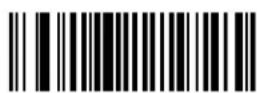
Enable Discrete 2 of 5

*Disable Discrete 2 of 5
Set Lengths for Discrete 2 of 5
The length of a code refers to the number of characters (i.e., human readable characters) the code contains, and includes check digits. Set lengths for D 2 of 5 to any length, one or two discrete lengths, or lengths within a specific range.
One Discrete Length - Select this option to decode only codes containing a selected length. Select lengths using the Numeric Bar Codes on page 10-93. For example, select D 2 of 5 One Discrete Length, then scan 1, 4, to decode only D 2 of 5 symbols containing 14 characters. To change the selection or cancel an incorrect entry, scan the Cancel bar code on page 10-95.

*D 2 of 5 - One Discrete Length
Two Discrete Lengths - Select this option to decode only codes containing two selected lengths. Select lengths using the Numeric Bar Codes on page 10-93. For example, select D 2 of 5 Two Discrete Lengths, then scan 0, 2, 1, 4, to decode only D 2 of 5 symbols containing 2 or 14 characters. To change the selection or cancel an incorrect entry, scan the Cancel bar code on page 10-95.
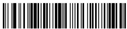
D 2 of 5 - Two Discrete Lengths
Length Within Range - Select this option to decode codes within a specified range. Select lengths using the Numeric Bar Codes on page 10-93. For example, to decode D 2 of 5 symbols containing between 4 and 12 characters, first scan D 2 of 5 Length Within Range, then scan 0, 4, 1 and 2 (enter a leading zero for single digit numbers). To change the selection or cancel an incorrect entry, scan the Cancel bar code on page 10-95.

D 2 of 5 - Length Within Range
Any Length - Scan this option to decode D 2 of 5 symbols containing any number of characters.

NOTE Selecting this option can lead to misdecodes for D 2 of 5 codes.

D 2 of 5 - Any Length
Codabar
Enable/Disable Codabar
To enable or disable Codabar, scan the appropriate bar code below.

Enable Codabar
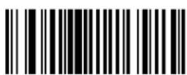
*Disable Codabar
Set Lengths for Codabar
The length of a code refers to the number of characters (i.e., human readable characters) the code contains, including start or stop characters. Set lengths for Codabar to any length, one or two discrete lengths, or lengths within a specific range.
One Discrete Length - Select this option to decode only codes containing a selected length. Select lengths using the Numeric Bar Codes on page 10-93. For example, select Codabar One Discrete Length, then scan 1, 4, to decode only Codabar symbols containing 14 characters. To change the selection or cancel an incorrect entry, scan the Cancel bar code on page 10-95.
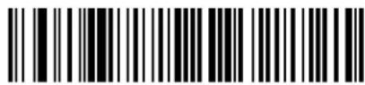
Codabar - One Discrete Length
Two Discrete Lengths - Select this option to decode only codes containing two selected lengths. Select lengths using the Numeric Bar Codes on page 10-93. For example, select Codabar Two Discrete Lengths, then scan 0, 2, 1, 4, to decode only Codabar symbols containing 2 or 14 characters. To change the selection or cancel an incorrect entry, scan the Cancel bar code on page 10-95.

Codabar - Two Discrete Lengths
Length Within Range - Select this option to decode a code within a specified range. Select lengths using the Numeric Bar Codes on page 10-93. For example, to decode Codabar symbols containing between 4 and 12 characters, first scan Codabar Length Within Range, then scan 0, 4, 1 and 2 (enter a leading zero for single digit numbers). To change the selection or cancel an incorrect entry, scan the Cancel bar code on page 10-95.
*Codabar - Length Within Range
Any Length - Scan this option to decode Codabar symbols containing any number of characters.

Codabar - Any Length
CLSI Editing
Enable this to strip the start and stop characters and insert a space after the first, fifth, and tenth characters of a 14-character Codabar symbol.

NOTE Symbol length does not include start and stop characters.
Enable CLSI Editing

*Disable CLSI Editing
NOTIS Editing
Enable this to strip the start and stop characters from decoded Codabar symbol.

Enable NOTIS Editing

*Disable NOTIS Editing
MSI Plessey
Enable/Disable MSI Plessey
To enable or disable MSI Plessey, scan the appropriate bar code below.

Enable MSI Plessey

*Disable MSI Plessey
Set Lengths for MSI Plessey
The length of a code refers to the number of characters (i.e., human readable characters) the code contains, and includes check digits. Set lengths for MSI Plessey to any length, one or two discrete lengths, or lengths within a specific range.
One Discrete Length - Select this option to decode only codes containing a selected length. Select lengths using the Numeric Bar Codes on page 10-93. For example, select MSI Plessey One Discrete Length, then scan 1, 4, to decode only MSI Plessey symbols containing 14 characters. To change the selection or cancel an incorrect entry, scan the Cancel bar code on page 10-95.

MSI Plessey - One Discrete Length
Two Discrete Lengths - Select this option to decode only codes containing two selected lengths. Select lengths using the Numeric Bar Codes on page 10-93. For example, select MSI Plessey Two Discrete Lengths, then scan 0, 2, 1, 4, to decode only MSI Plessey symbols containing 2 or 14 characters. To change the selection or cancel an incorrect entry, scan the Cancel bar code on page 10-95.

MSI Plessey - Two Discrete Lengths
Length Within Range - Select this option to decode codes within a specified range. Select lengths using the Numeric Bar Codes on page 10-93. For example, to decode MSI Plessey symbols containing between 4 and 12 characters, first scan MSI Plessey Length Within Range, then scan 0, 4, 1 and 2 (Enter a leading zero for single digit numbers). To change the selection or cancel an incorrect entry, scan the Cancel bar code on page 10-95.

*MSI Plessey - Length Within Range
Any Length - Scan this option to decode MSI Plessey symbols containing any number of characters.

NOTE Selecting this option can cause misdecodes for MSI Plessey codes.

MSI Plessey - Any Length
MSI Plessey Check Digits
These check digits at the end of the bar code verify the integrity of the data. At least one check digit is required. Check digits are not automatically transmitted with the data.

*One MSI Plessey Check Digit
If you select two check digits, also select an MSI Plessey Check Digit Algorithm. See page 10-68.

Two MSI Plessey Check Digits
Transmit MSI Plessey Check Digit
Scan this symbol to transmit the check digit with the data.

Transmit MSI Plessey Check Digit (Enable)
Scan this symbol to transmit data without the check digit.

*Do Not Transmit MSI Plessey Check Digit (Disable)
MSI Plessey Check Digit Algorithm
If you selected Two MSI Plessey Check Digits, an additional verification is required to ensure integrity. Select one of the following algorithms.
MOD 10/ MOD 11

*MOD 10/ MOD 10
PDF417/MicroPDF417
NOTE Only the Symbol MS2207, MS2207VHD, and MS3207 support these options.
Enable/Disable PDF417
To enable or disable PDF417, scan the appropriate bar code below.
Enable PDF417
Disable PDF417
Enable/Disable MicroPDF417
To enable or disable MicroPDF417, scan the appropriate bar code below.
Enable MicroPDF417
*Disable MicroPDF417
MicroPDF Performance
If you have problems decoding MicroPDF symbols, select Selective Performance.
This can decrease decoding aggressiveness on some symbols.

*Standard Performance for MicroPDF
Selective Performance for MicroPDF
Code 128 Emulation
Enable this parameter to transmit data from certain MicroPDF417 symbols as Code 128. You must enable Transmit AIM Symbology Identifiers for this parameter to work.
Enabling Code 128 Emulation transmits these MicroPDF417 symbols with one of the following prefixes:
]C1 if the first codeword is 903-907, 912, 914, 915
]C2 if the first codeword is 908 or 909
]C0 if the first codeword is 910 or 911
Disabling this transmits them with one of the following prefixes:
]L3 if the first codeword is 903-907, 912, 914, 915
]L4 if the first codeword is 908 or 909
]L5 if the first codeword is 910 or 911
Scan a bar code below to enable or disable Code 128 Emulation.

Enable Code 128 Emulation

*Disable Code 128 Emulation
GS1 DataBar
GS1 DataBar-14
To enable or disable GS1 DataBar-14, scan the appropriate bar code below.

Enable GS1 DataBar-14
*Disable GS1 DataBar-14
GS1 DataBar Limited
To enable or disable GS1 DataBar Limited, scan the appropriate bar code below.

Enable GS1 DataBar Limited

*Disable GS1 DataBar Limited
GS1 DataBar Expanded
To enable or disable GS1 DataBar Expanded, scan the appropriate bar code below.
Enable GS1 DataBar Expanded

*Disable GS1 DataBar Expanded
Convert GS1 DataBar to UPC/EAN

NOTE The Symbol MS1207FZY and MS1207WA only support this option.
This parameter only applies to GS1 DataBar-14 and GS1 DataBar Limited symbols not decoded as part of a Composite symbol. When this conversion is enabled, DataBar-14 and DataBar Limited symbols encoding a single zero as the first digit have the leading '010' stripped and the bar code reported as EAN-13.
Bar codes beginning with two or more zeros but not six zeros have the leading '0100' stripped and the bar code reported as UPC-A. The UPC-A Preamble parameter to transmit the system character and country code applies to converted bar codes. Note that neither the system character nor the check digit can be stripped.
Enable Convert GS1 DataBar to UPC/EAN

*Disable Convert GS1 DataBar to UPC/EAN
Composite

NOTE Only the Symbol MS2207, MS2207VHD, and MS3207 support these options.
Composite CC-C
Scan a bar code below to enable or disable Composite bar codes of type CC-C.

Enable CC-C
*Disable CC-C
Composite CC-A/B
Scan a bar code below to enable or disable Composite bar codes of type CC-A/B.
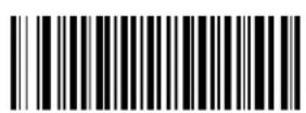
Enable CC-A/B

*Disable CC-A/B
Composite TLC-39
Scan a bar code below to enable or disable Composite bar codes of type TLC-39.

Enable TLC39
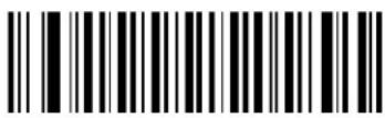
*Disable TLC39
UPC Composite Mode
UPC symbols can be “linked” with a 2D symbol during transmission as if they were one symbol. Three options are offered for these symbols:
- Select UPC Never Linked to transmit UPC bar codes regardless of whether a 2D symbol is detected.
- Select UPC Always Linked to transmit UPC bar codes and the 2D portion. If 2D is not present, the UPC bar code does not transmit.
- If Autodiscriminate UPC Composites is selected, the scanner determines if there is a 2D portion, then transmits the UPC, as well as the 2D portion if present.

UPC Never Linked

*UPC Always Linked

Autodiscriminate UPC Composites
Data Options
Transmit Code ID Character
A code ID character identifies the code type of a scanned bar code. This is useful when decoding more than one code type. The code ID character is inserted between the prefix character (if selected) and the decoded symbol.
Select no code ID character, a Symbol Code ID character, or an AIM Code ID character. The Symbol Code ID characters are listed below.
Table 10-2 Symbol Code ID Characters
| Code Type Symbol Identifier | |
| UPC-A, UPC-E, UPC-E1, EAN-13, EAN-8 A | |
| Code 39, Code 32 B | |
| Codabar C | |
| Code 128, ISBT 128 D | |
| Code 93 E | |
| Interleaved 2 of 5 F | |
| Discrete 2 of 5, D 2of 5 IATA G | |
| Code 11 H | |
| MSI Plessey J | |
| UCC/EAN 128 K | |
| Bookland EAN | L |
| Trioptic Code 39 | M |
| Coupon Code | N |
| GS1 DataBarGS1 DataBar (all variants) | R |
| Composite* | T |
| Scanlet | W |
| PDF417, Micro PDF417, Macro PDF417, Micro MacroPDF417 | X |
*Note: UPC/EAN Composite transmits in two portions, each with a "T" prefix.
Transmit Code ID Character (continued)
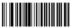
Symbol Code ID Character

AIM Code ID Character

*None
Prefix/Suffix Values
You can append a prefix and/or one or two suffixes to scan data to use in data editing. To set a value for a prefix or suffix, scan a four-digit number (i.e., four bar codes; see Numeric Bar Codes beginning on page 10-93) that corresponds to that value. See Table A-1 on page A-1 for the four-digit codes.
To change the selection or cancel an incorrect entry, scan the Cancel bar code on page 10-95.

NOTE In order to use Prefix/Suffix values, first set the Scan Data Transmission Format on page 10-80.

Scan Prefix

Scan Suffix 1

Scan Suffix 2

Data Format Cancel
Scan Data Transmission Format
To change the Scan Data Transmission Format, scan the Scan Options bar code below, then select one of four options:
- Data As Is
-

NOTE To set values for the prefix and/or suffix, see Prefix/Suffix Values on page 10-79.
After making a selection, scan the Enter bar code on page 10-81. To change the selection or to cancel an incorrect entry, scan the Data Format Cancel bar code on page 10-81.
To add a carriage return/enter after each bar code scanned, scan the following bar codes in order:
-
- Enter (on page 10-81).
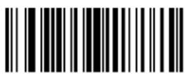
Scan Options
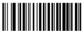
*Data As Is
Scan Data Transmission Format (continued)


Enter
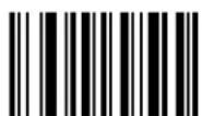
Data Format Cancel
Event Reporting
The host can request the decoder to provide certain information (events) relative to the decoder's behavior. Enable or disable the events listed in Table 10-3 by scanning the appropriate bar codes on the following pages. Parameter number format for these parameters follows those shown in the Simple Serial Interface (SSI) Programmer's Guide for parameters numbered 256 or higher.
Table 10-3 Event Codes
| Event Class Event | Code Reported |
| Decode Event Non-parameter decode 01h | |
| Boot Up Event System power-up 03h | |
| Parameter Event Parameter entry error | 07h |
| Parameter stored | 08h |
| Defaults set (and parameter event is enabled by default) | 0Ah |
| Number expected | 0Fh |
Decode Event
When enabled, the scanner sends a message to the host when it successfully decodes a bar code. When disabled, no message is sent.

Enable

*Disable
Boot Up Event
When enabled, the scanner sends a message to the host when power is applied. When disabled, no message is sent.

Enable

*Disable
Parameter Event
When enabled, the scanner sends a message to the host when one of the events specified in Table 10-3 on page 10-82 occurs. When disabled, no message is sent.

Enable

*Disable
Macro PDF Features

NOTE Only the Symbol MS2207, MS2207VHD, and MS3207 support these options.
Transmit Symbols in Codeword Format
Enable this to transmit each PDF symbol as directly decoded data codewords, whether or not that symbol is part of a macro PDF sequence. Note that data is output as codeword values, not as interpreted data.
“Codeword values” is an ASCII representation of a number from 000 to 928 for each codeword, preceded by an escape character. This escape character is a backslash by default, but you can change this value. For example, the codeword value 005 is sent to the host in the form of \005 for GLIs, and \C005C for ECIs. This output format is based on the AIM USA Uniform Symbology Specification for PDF417 (1994).
All output codewords are exactly 4 characters for GLIs and 6 characters for ECIs. However, there can be non-decodable characters in the PDF symbol, such as a GLI sequence. This special codeword sequence activates a certain kind of interpretation to the encoded data. Non-decodable codewords like GLIs are embedded in the output stream like any other codeword, e.g., \927\001.
Because GLIs are indistinguishable from other codewords in the output data stream, the host must recognize them as GLIs and process their interpretations.
Note that when a macro PDF sequence is transmitted, the last character in the last block of data transmitted is always \922 (if selected). This indicates the end of that macro PDF transmission.
Scan the appropriate bar code to enable or disable this.

Enable Transmit In Codeword Format

*Disable Transmit In Codeword Format
Transmit Unknown Codewords
Select Transmit Unknown Codewords to use the output codeword format for transmitting any non-GLI or non-macro PDF codeword. Select Do Not Transmit Unknown Codewords to sound a decode error beep when an unknown codeword is found.

Transmit Unknown Codewords

*Do Not Transmit Unknown Codewords
Escape Characters
This enables the backslash () character as an Escape character for systems that can process transmissions containing special data sequences. Scan a bar code below to either format special data (e.g., GLI escapes, MacroPDF417 Control Block optional fields) according to the GLI (Global Label Identifier) protocol or the ECI (Extended Channel Interpretation) protocol, or to disable this parameter.

ECI Protocol

GLI Protocol

*None
Delete Character Set ECIs
Select Delete Character Set ECIs to delete any escape sequences representing Character Set ECIs (also known as GLIs) from its buffer before transmission. In many receiving systems, Character Set ECIs can be removed without affecting the way data is displayed or processed.
Select Transmit Character Set ECIs to transmit data from PDF417 and MicroPDF417 bar codes containing Character Set ECIs, even when the ECI Protocol is disabled.
Scan a bar code to delete or transmit character set ECIs.

Delete Character Set ECIs
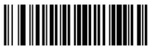
*Transmit Character Set ECIs
ECI Decoder
This parameter enables the scanner to interpret any Extended Channel Interpretations (ECIs) that are supported by the scanner firmware. This does not affect symbols not encoded using ECIs. This version of the product supports ECIs 000900 through 000913, used for efficient encoding of Common Data Syntax Format 00-99. If this parameter is disabled, and a symbol is scanned that was encoded using an ECI escape, the scanner transmits the ECI escape followed by the uninterpreted data.
Scan a bar code to enable or disable this option.

*Enable ECI Decoder
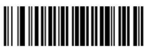
Disable ECI Decoder
Transmit Macro PDF User-Selected Fields

NOTE Only the Symbol MS2207, MS2207VHD, and MS3207 support these options.
Enable or disable each of the following parameters to indicate whether or not to transmit the specified field in subsequently scanned Macro PDF417 symbols. The options cannot be changed in the middle of a Macro PDF set entry. All user-selected fields are prefixed by \923 for GLIs, and \C923C for ECIs. Tags and examples in the following parameters demonstrate GLI protocol, but the ECI tag (\C923C) can be used instead if ECI protocol is enabled.
Transmit File Name
Parameter # B0h
Transmit File Name activates transmission of the file name field. The field character tag is \923\000. For example, the filename MANHOURS.WK1 is sent as: \923\000MANHOURS.WK1.

Enable File Name Transmit
Transmit Block Count
Transmit Block Count activates transmission of the block count field. The field character tag is \923\001. For example, the field may be: \923\0011856.
Enable Transmit Block Count

*Disable Transmit Block Count
Transmit Time Stamp
Transmit Time Stamp activates transmission of the time stamp field. The field character tag is \923\002. For example, the field may be: \923\0022123443243234.

Enable Transmit Time Stamp

*Disable Transmit Time Stamp
Transmit Sender
Transmit Sender activates transmission of the sender field. The field character tag is \923\003. For example, the field may be: \923\003Motorola Holtsville, NY.
Enable Sender Transmit
Transmit Addressee activates transmission of the addressee field. The field character tag is \923\004. For example, the field may be: \923\004AIM USA.

Enable Addressee Transmit

*Disable Addressee Transmit
Transmit Checksum
Transmit Checksum activates transmission of the checksum field. The field character tag is \923\006. For example, the field may be: \923\00663823.

Enable Checksum Transmit
*Disable Checksum Transmit
Transmit File Size
Transmit File Size activates transmission of the file size field. The field character tag is \923\005. For example, the field may be: \923\005179234.

Enable File Size Transmit

*Disable File Size Transmit
Transmit Macro PDF Control Header
Transmit Macro PDF Control Header activates transmission of the control header, which contains the segment index and the file ID. For example, the field can be: \92800000\725\120\343. The five digits after the \928 are the segment index (or block index), and \725\120\343 is the file ID.

Enable Macro PDF Control Header Transmit

*Disable Macro PDF Control Header Transmit
Last Blocker Marker
Enable Last Block Marker marks the last block in the set by the codeword \922.

Enable Last Block Marker
*Disable Last Block Marker
Numeric Bar Codes
For parameters requiring specific numeric values, scan the appropriately numbered bar code(s).
0

1
2
3

4
Numeric Bar Codes (continued)

5

6

7

8
9
Cancel
To change a selection or cancel an incorrect entry, scan the bar code below.

Cancel
Chapter 11 RS-232 Interface
Introduction
This chapter provides RS-232 host information for setting up the MiniScan XX07 Series scanner. The RS-232 interface connects the MiniScan scanner to point-of-sale devices, host computers, or other devices with an available RS-232 port (e.g., com port).
If Table 11-2 does not list your host, set the communication parameters to match the host device. Refer to the documentation for the host device.
This scanner uses TTL RS-232 levels which interface with all PCs with no additional hardware.

NOTE Particularly noisy electrical environments may require a cable with an RS-232 transceiver. To obtain this cable contact Motorola Enterprise Mobility Support.
Throughout the programming bar code menus, asterisks (*) indicate default values.

* Indicates Default
Baud Rate 9600
Feature/Option
RS-232 Default Parameters
Table 11-1 lists the defaults for RS-232 host parameters. To change any option, scan the appropriate bar code(s) in the Parameter Descriptions section beginning on page 11-5.

NOTE See Chapter 9, Maintenance and Troubleshooting for all user preferences, hosts, symbologies, and miscellaneous parameters.
Table 11-1 RS-232 Host Default Table
| Parameter Default | Page Number | |
| RS-232 Host Parameters | ||
| RS-232 Host Types | Standard 1 | 11-5 |
| Baud Rate 9600 | 11-7 | |
| Parity Type None | 11-8 | |
| Stop Bit Select 1 Stop Bit | 11-9 | |
| Data Bits 8-Bit | 11-9 | |
| Check Receive Errors Enable | 11-10 | |
| Hardware Handshaking None | 11-10 | |
| Software Handshaking None | 11-12 | |
| Host Serial Response Time-out | 2 Sec | 11-14 |
| RTS Line State | Low RTS | 11-15 |
| Beep on | Disable | 11-15 |
| Intercharacter Delay | 0 msec | 11-16 |
| Nixdorf Beep/LED Options | Normal Operation | 11-17 |
| Ignore Unknown Characters | Send Bar Code | 11-17 |
| 1User selection is required to configure this interface; this is the most common selection. | ||
RS-232 Host Parameters
Various RS-232 hosts use their own parameter default settings (Table 11-2). Selecting the ICL, Fujitsu, Wincor-Nixdorf Mode A, Wincor-Nixdorf Mode B, Olivetti, Omron, or standard sets the defaults listed below.
Table 11-2 Terminal Specific RS-232
| Parameter | Standard (Default) | ICL Fujitsu | Wincor-Nixdorf Mode A | Wincor-Nixdorf Mode B/ OPOS | Olivetti Omron | ||
| Transmit Code ID No Yes Yes Yes Yes Yes | |||||||
| Data Transmission Format | Data as is Data/Suffix Data/Suffix Data/Suffix Data/Suffix Prefix/Data/Suffix | Data/Suffix | |||||
| Suffix CR/LF(7013) | CR (1013) CR (1013) CR | (1013) CR (1013) ETX (1003) CR (1013) | |||||
| Baud Rate | 9600 | 9600 | 9600 | 9600 | 9600 | 9600 | 9600 |
| Parity | None | Even | None | Odd | Odd | Even | None |
| Hardware Handshaking | None | RTS/CTS Option 3 | None | RTS/CTS Option 3 | RTS/CTS Option 3 | None | None |
| Software Handshaking | None | None | None | None | None | Ack/Nak | None |
| Serial Response Time-out | 2 Sec. | 9.9 Sec. | 2 Sec. | 9.9 Sec. | 9.9 Sec. | 9.9 Sec. | 9.9 Sec. |
| Stop Bit Select | One | One | One | One | One | One | One |
| ASCII Format | 8-Bit | 8-Bit | 8-Bit | 8-Bit | 8-Bit | 7-Bit | 8-Bit |
| Beep OnDisableDisableDisableDisableDisableDisable | Disable | Disable | Disable | Disable | Disable | Disable | Disable |
| RTS Line State | Low | High | Low | Low | Low = No data to send | Low | High |
| Prefix | None | None | None | None | None | STX (1002) | None |
*In the Nixdorf Mode B, if CTS is low, scanning is disabled. When CTS is high, scanning is enabled. **If Nixdorf Mode B is scanned without the scanner connected to the proper host, the scanner may not be able to scan. If this happens, scan a different RS-232 host type within 5 seconds of cycling power to the scanner.
RS-232 Host Parameters (continued)
Selecting the ICL, Fujitsu, Wincor-Nixdorf Mode A, Wincor-Nixdorf Mode B, OPOS, Olivetti, or Omron terminal enables the transmission of code ID characters listed in Table 11-3. These code ID characters are not programmable and are separate from the Transmit Code ID feature. Do not enable the Transmit Code ID feature for these terminals.
Table 11-3 Terminal-Specific Code ID Characters
| Parameter ICL Fujitsu | Wincor-Nixdorf Mode A | Wincor-Nixdorf Mode B/OPOS | Olivetti Omron | |||
| U | P | C | - | A | A | A |
| U | P | C | - | E | E | E |
| E | A | N | - | 8 | / | J |
| E | A | N | - | 1 | 3 | / |
| Code 39 | C | None | M | M | M | C |
| Codabar | N | None | N | N | N | N |
| Code 128 | L | None | K | K | K | L |
| I 2 of 5 | I | None | I | I | I | I |
| Code 93 | None | None | L | L | L | None |
| D 2 of 5 | H | None | H | H | H | H |
| UCC/EAN 128 | L | None | P | P | P | L |
| MSI | None | None | O | O | O | None |
| B | o | o | k | l | a | n |
| Trioptic | None | None | None | None | None | None |
| Code 11 | None | None | None | None | None | None |
| IATA | H | None | H | H | None | None |
| Code 32 | None | None | None | None | None | None |
RS-232 Host Types
To select an RS-232 host interface, scan one of the following bar codes.

NOTE You must select an interface as there is no default; Standard RS-232 is the most common selection.

Standard RS-232

ICL RS-232

Wincor-Nixdorf RS-232 Mode A

Wincor-Nixdorf RS-232 Mode B
RS-232 Host Types (continued)
Fujitsu RS-232
Baud Rate
Baud rate is the number of bits of data transmitted per second. Set the scanner's baud rate to match the host's baud rate setting, or data may not reach the host device or may reach it in distorted form.

Baud Rate 600
Baud Rate 1200

Baud Rate 2400

Baud Rate 4800

*Baud Rate 9600

Baud Rate 19,200

Baud Rate 38,400
Parity
A parity check bit is the most significant bit of each ASCII coded character. Select the parity type according to host device requirements.
Select Odd parity to set the parity bit value to 0 or 1, based on data, to ensure that an odd number of 1 bits are contained in the coded character.

Odd
Select Even parity to set the parity bit value to 0 or 1, based on data, to ensure that an even number of 1 bits are contained in the coded character.
Even
Select Mark parity and the parity bit is always 1.
Mark
Select Space parity and the parity bit is always 0.

Space
Select None when no parity bit is required.

*None
Stop Bit Select
The stop bit(s) at the end of each transmitted character marks the end of transmission of one character and prepares the receiving device for the next character in the serial data stream. Select the number of stop bits (one or two) the host device is programmed to accommodate.

*1 Stop Bit

2 Stop Bits
Data Bits
This parameter allows the scanner to interface with devices requiring a 7-bit or 8-bit ASCII protocol.
7-Bit
*8-Bit
Check Receive Errors
Select whether or not to check the parity, framing, and overrun of received characters. The parity value of received characters is verified against the parity parameter selected earlier.
*Check For Received Errors

Do Not Check For Received Errors
Hardware Handshaking
The data interface consists of an RS-232 port designed to operate either with or without the hardware handshaking lines, Request to Send (RTS), and Clear to Send (CTS).
Disable Standard RTS/CTS handshaking to transmit scan data as it becomes available. Select Standard RTS/CTS handshaking to transmit scan data according to the following sequence:
- The scanner reads the CTS line for activity. If CTS is asserted, the scanner waits up to the Host Serial Response Time-out for the host to negate the CTS line. If, after the Host Serial Response Time-out (default), the CTS line is still asserted, the scanner sounds a transmit error and discards any scanned data.
- When the CTS line is negated, the scanner asserts the RTS line and waits up to the Host Serial Response Time-out for the host to assert CTS. When the host asserts CTS, the scanner transmits the data. If, after the Host Serial Response Time-out (default), the CTS line is not asserted, the scanner sounds a transmit error, and discards the data.
- When data transmission is complete, the scanner negates RTS 10 msec after sending the last character.
- The host responds by negating CTS. The scanner checks for a negated CTS upon the next transmission of data.
During data transmission, the CTS line should be asserted. If CTS is deasserted for more than 50 ms between characters, the transmission is aborted, the scanner sounds a transmission error, and the data is discarded.
If this communications sequence fails, the scanner issues an error indication. In this case, the data is lost and must be rescanned.
If Hardware Handshaking and Software Handshaking are both enabled, Hardware Handshaking takes precedence.

NOTE The DTR signal is jumpered to the active state.
None
Scan the bar code below if to disable Hardware Handshaking.

Standard RTS/CTS
Scan the bar code below to select Standard RTS/CTS Hardware Handshaking.
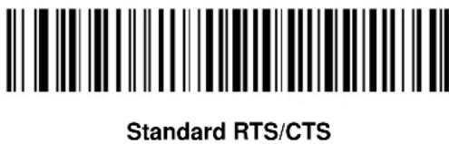
RTS/CTS Option 1
When RTS/CTS Option 1 is selected, the scanner asserts RTS before transmitting and ignores the state of CTS. The scanner de-asserts RTS when the transmission is complete.

RTS/CTS Option 2
When Option 2 is selected, RTS is always high or low (user-programmed logic level). However, the scanner waits for CTS to be asserted before transmitting data. If CTS is not asserted within the Host Serial Response Time-out (default), the scanner issues an error indication and discards the data.

RTS/CTS Option 3
When Option 3 is selected, the scanner asserts RTS prior to any data transmission, regardless of the state of CTS. The scanner waits up to the Host Serial Response Time-out (default) for CTS to be asserted. If CTS is not asserted during this time, the scanner issues an error indication and discards the data. The scanner de-asserts RTS when transmission is complete.

Software Handshaking
This parameter offers control of the data transmission process in addition to, or instead of, that offered by hardware handshaking. There are five options.
If Software Handshaking and Hardware Handshaking are both enabled, Hardware Handshaking takes precedence.
None
When this option is selected, data is transmitted immediately.

*None
ACK/NAK
When this option is selected, after transmitting data, the scanner expects either an ACK or NAK response from the host. When the scanner receives a NAK, it re-transmits the data and waits for either an ACK or NAK. After three unsuccessful attempts to send data, the scanner issues an error indication and discards the data.
The scanner waits up to the programmable Host Serial Response Time-out to receive an ACK or NAK. If the scanner does not get a response in this time, it issues an error indication and discards the data. There are no retries when a time-out occurs.

ACK/NAK
ENQ
When this option is selected, the scanner waits for an ENQ character from the host before transmitting data. If the scanner does not receive an ENQ within the Host Serial Response Time-out, it issues an error indication and discards the data. The host must transmit an ENQ character at least every Host Serial Response Time-out to prevent transmission errors.
ENQ
ACK/NAK with ENQ
This combines the two previous options.
ACK/NAK with ENQ
XON/XOFF
An XOFF character turns the scanner transmission off until the scanner receives an XON character. There are two situations for XON/XOFF:
- The scanner receives XOFF before has it data to send. When the scanner has data to send, it waits up to Host Serial Response Time-out for an XON character before transmission. If the scanner does not receive an XON within this time, it issues an error indication and discards the data.
- The scanner receives XOFF during a transmission. Data transmission then stops after sending the current byte. When the scanner receives an XON character, it sends the rest of the data message. The scanner waits indefinitely for the XON.
XON/XOFF
Host Serial Response Time-out
This parameter specifies how long the scanner waits for an ACK, NAK, or CTS before determining that a transmission error occurred. This only applies if you enabled an ACK/NAK Software Handshaking mode or RTS/CTS Hardware Handshaking mode.
*Minimum: 2 Sec

Low: 2.5 Sec

Medium: 5 Sec

High: 7.5 Sec
Maximum: 9.9 Sec
RTS Line State
This parameter sets the idle state of the Serial Host RTS line. Scan a bar code below to select Low RTS or High RTS line state.
*Host: Low RTS

Host: High RTS
Beep on
When this parameter is enabled, the scanner issues a beep when a

Beep On
*Do Not Beep On
Intercharacter Delay
This parameter specifies the intercharacter delay inserted between character transmissions.

*Minimum: 0 msec
Low: 25 msec

Medium: 50 msec
High: 75 msec

Maximum: 99 msec
Nixdorf Beep/LED Options
When Nixdorf Mode B is selected, this indicates when the scanner beeps and turns on its LED after a decode.
*Normal Operation (Beep/LED immediately after decode)

Beep/LED After Transmission

Beep/LED After CTS Pulse
Ignore Unknown Characters
Unknown characters are characters the host does not recognize. Select Send Bar Codes with Unknown Characters to transmit all bar code data except for unknown characters. The scanner sounds no error beeps. Select Do Not Send Bar Codes With Unknown Characters to send bar code data up to the first unknown character. The scanner sounds four error beeps.

*Send Bar Code With Unknown Characters
Do Not Send Bar Codes With Unknown Characters
Chapter 12 USB Interface
Introduction
This chapter describes how to connect and configure the Symbol MSXX07 Series scanner with a USB host. The MiniScan attaches directly to a USB host, or a powered USB hub, which powers it. No additional power supply is required. See Connecting the Symbol MSXX07 via USB on page 2-7 for more information.
Throughout the programming bar code menus, asterisks (*) indicate default values.

*North American, Standard USB Keyboard
* Indicates Default
Feature/Option
Connecting a USB Interface
The scanner connects with USB hosts including:
• Desktop PCs and Notebooks
- Apple™ iMac, G4, iBooks (North America only)
• IBM SurePOS terminals
- Sun, IBM, and other network computers that support more than one keyboard.
The following operating systems support the scanner through USB:
• Windows 98, 2000, ME, XP
• MacOS 8.5 and above
- IBM 4690 OS.
The scanner also interfaces with other USB hosts that support USB Human Interface Devices (HID). For more information on USB technology, hosts, and peripheral devices, visit www.symbol.com/usb.
USB Default Parameters
Table 12-1 lists the defaults for USB host parameters. To change any option, scan the appropriate bar code(s) provided in USB Host Parameters on page 12-3.

NOTE See Chapter 9, Maintenance and Troubleshooting for all user preferences, hosts, symbologies, and miscellaneous default parameters.
Table 12-1 USB Host Parameters Default Table
| Parameter Default | Page Number | |
| USB Device Type HID Keyboard Emulation | 12-3 | |
| USB Country Keyboard Types (Country Codes) North American | 12-4 | |
| USB Keystroke Delay No Delay | 12-7 | |
| USB CAPS Lock Override Disable | 12-8 | |
| USB Ignore Unknown Characters Enable | 12-9 | |
| Emulate Keypad Disable | 12-9 | |
| USB FN1 Substitution Disable | 12-10 | |
| Function Key Mapping Disable | 12-10 | |
| Simulated Caps Lock Disable | 12-11 | |
| Convert Case | None | 12-11 |
USB Host Parameters
USB Device Type
Select the desired USB device type.

NOTE When changing USB Device Types, the scanner automatically restarts and issues the standard startup beep sequences.
*HID Keyboard Emulation

IBM Table Top USB
IBM Hand-Held USB
USB Country Keyboard Types (Country Codes)
Scan the bar code corresponding to the keyboard type. This setting applies only to the USB HID Keyboard Emulation device.

*North American Standard USB Keyboard

German Windows

French Windows
USB Country Keyboard Types (continued)

French Canadian Windows 95/98

French Canadian Windows 2000/XP

Spanish Windows

Italian Windows
USB Country Keyboard Types (continued)

Swedish Windows
UK English Windows

Japanese Windows (ASCII)
Portuguese-Brazilian Windows
USB Keystroke Delay
This parameter sets the delay, in milliseconds, between emulated keystrokes. Scan a bar code below to increase the delay when hosts require a slower transmission of data.
*No Delay

Medium Delay (20 msec)
Long Delay (40 msec)
USB CAPS Lock Override
This option applies only to the HID Keyboard Emulation device. When enabled, the case of the data is preserved regardless of the state of the caps lock key. This setting is always enabled for the Japanese, Windows (ASCII) keyboard type.

Override Caps Lock Key (Enable)

*Do Not Override Caps Lock Key (Disable)
USB Ignore Unknown Characters
This option applies only to the HID Keyboard Emulation device and IBM device. Unknown characters are characters the host does not recognize. Select Send Bar Codes With Unknown Characters to send all bar code data except for unknown characters. No error beeps sound. When Do Not Send Bar Codes With Unknown Characters is selected, bar codes containing at least one unknown character are not sent to the host, and an error beep sounds.
*Send Bar Codes With Unknown Characters (Transmit)

Do Not Send Bar Codes with Unknown Characters (Disable)
Emulate Keypad
When enabled, all characters are sent as ASCII sequences over the numeric keypad. For example ASCII A is sent as "ALT make" 0 6 5 "ALT Break".

*Disable Keypad Emulation
Enable Keypad Emulation
USB Keyboard FN 1 Substitution
This option applies only to the USB HID Keyboard Emulation device. Enable this to replace any FN 1 characters in an EAN 128 bar code with a Key Category and value.

Enable

*Disable
ASCII values under 32 are normally sent as a control-key sequences (see Table A-2 on page A-6). Enable this to send the keys in bold in place of the standard key mapping. Table entries that do not have a bold entry remain the same whether or not this parameter is enabled.

*Disable Function Key Mapping
Enable Function Key Mapping
Simulated Caps Lock
Enable this to invert upper and lower case characters on the scanned bar code as if the Caps Lock state is enabled on the keyboard. This is done regardless of the current state of the keyboard's Caps Lock state.

*Disable Simulated Caps Lock

Enable Simulated Caps Lock
Convert Case
Enable this to convert all bar code data to the selected case.

*No Case Conversion

Convert All to Upper Case

Convert All to Lower Case
12 - 12 Symbol MiniScan MSXX07 Series Integration Guide
Chapter 13 Advanced Data Formatting
Introduction
Advanced Data Formatting (ADF) is a means of customizing data before transmission to the host device. Scan data can be edited to suit particular requirements.
Implement ADF by scanning a related series of bar codes, which begin on page 13-8, that programs the scanner with ADF rules.
Avoid using ADF formatting with bar codes containing more than 60 characters. To add a prefix or suffix value for such bar codes, use Add Prefix/Suffix setting. Using ADF with longer bar codes transmits the bar code in segments of length 252 or less (depending on the host selected), and applies the rule to each segment
Rules: Criteria Linked to Actions
ADF uses rules to customize data. These rules perform detailed actions when the data meets certain criteria. One rule may consist of single or multiple criteria applied to single or multiple actions.
For instance, a data formatting rule could be:
Criteria: When scan data is Code 39, length 12, and data at the start position is the string "129",
Actions: pad all sends with zeros to length 8, send all data up to X, send a space.
If you scan a Code 39 bar code of 1299X1559828, the following transmits: 00001299
The rule specifies the editing conditions and requirements before data transmission occurs.
Using ADF Bar Codes
When programming a rule, make sure the rule is logically correct. Plan ahead before scanning.
To program each data formatting rule:
- Start the Rule. Scan the Begin New Rule bar code on page 13-8.
- Criteria. Scan the bar codes for all pertinent criteria. Criteria can include code type (e.g., Code 128), code length, or data that contains a specific character string (e.g., the digits "129"). These options are described in Criteria on page 13-11.
- Actions. Scan all actions related to, or affecting, these criteria. The actions of a rule specify how to format the data for transmission. These options are described in ADF Bar Code Menu Example on page 13-2.
- Save the Rule. Scan the Save Rule bar code on page 13-8. This places the rule in the "top" position in the rule buffer.
- Erase criteria, actions, and entire rules by scanning the appropriate bar code on page 13-9.
ADF Bar Code Menu Example
This section provides an example of how to enter ADF rules for scan data.
An auto parts distribution center wants to encode manufacturer ID, part number, and destination code into their own Code 128 bar codes. The distribution center also has products that carry UPC bar codes, placed there by the manufacturer. The Code 128 bar codes have the following format:
MMMMPPPPPDD
Where: M = Manufacturer ID
P = Part Number
D = Destination Code
The distribution center uses a PC with dedicated control characters for manufacturer ID
The following rules must be entered:
When scanning data of code type Code 128, send the next 5 characters, send the manufacturer ID key
When scanning data of code type UPC/EAN, send all data, send the manufacturer ID key
To enter these rules, see the following steps:
Rule 1: The Code 128 Scanning Rule
Step Bar Code On Page Beep Indication
1 Begin New Rule 13-8 High High
2 Code 128 13-11 High High
3 Send next 5 characters 13-26 High High
4 Send
5 Send next 5 characters 13-26 High High
6 Send
7 Send next 2 characters 13-25 High High
8 Send
9 Save Rule 13-8 High Low High Low
Rule 2: The UPC Scanning Rule
Step Bar Code On Page Beep Indication
1 Begin New Rule 13-8 High High
2 UPC/EAN 13-13 High High
4 Send
5 Save Rule 13-8 High Low High Low
3 Send all remaining data 13-25 High High
To correct any errors made while entering this rule, scan the Quit Entering Rules bar code on page 13-9. If you already saved the rule, scan the Erase Previously Saved Rule bar code on page 13-9.
Alternate Rule Sets
Group ADF rules into one of four alternate sets which you can turn on and off when needed. This is useful to format the same message in different ways. For example, a Code 128 bar code contains the following information:
Class (2 digits), Stock Number (8) digits, Price (5 digits)
The bar code might look like this:
245671243701500
where:
Class = 24
Stock Number = 56712437
Price = 01500
Ordinarily, data is sent as follows:
24 (class key)
56712437 (stock key)
01500 (enter key)
But, when there is a sale, send only the following:
24 (class key)
56712437 (stock key)
and the cashier keys the price manually.
To implement this, first enter an ADF rule that applies to the normal situation, such as:
Scan Rule Belongs to Set 1. When scanning a bar code of length 15, send the next 2 characters, send the class key, send the next 8 characters, send the stock key, send the data that remains, send the Enter key.
The "sale" rule may look like this:
Scan Rule Belongs to Set 2. When scanning a bar code of length 15, send the next 2 characters, send the class key, send the next 8 characters, send the stock key.
To switch between the two sets of rules, program a “switching rule” to specify the type of bar code that must be scanned to switch between the rule sets. For example, in the case of the “sale” rule above, the rule programmer wants the cashier to scan the bar code “M” before a sale. To do this, enter the following rule:
When scanning a bar code of length 1 that begins with "M", select rule set number 1.
Program another rule to switch back.
When scanning a bar code of length 1 that begins with "N", turn off rule set number 1.
Or include the switching back to normal rules in the "sale" rule:
When scanning a bar code of length 15, send the next 2 characters, send the class key, send the next 8 characters, send the stock key, turn off rule set 1.
For optimal results, scan the Disable All Rule Sets bar code on page 13-10 after programming a rule belonging to an alternate rule set.
In addition to enabling and disabling rule sets within the rules, enable or disable them by scanning the appropriate bar codes on page 13-10.
Rules Hierarchy (in Bar Codes)
The order of programming individual rules is important. Program the most general rule first.
All programmed rules are stored in a buffer. As they are programmed, they are stored at the "top" of a rules list. If you created three rules, the list is configured as follows:
Third Rule
Second Rule
First Rule
When scanning data, the rules list is checked from top to bottom to determine if the criteria matches (and therefore, if the actions occur). Input is modified into the data format specified by the first matching set of criteria it finds. Be sure to program the most general rule first.
For example, if the THIRD rule states:
When scanning a bar code of any length, send all data, then send the ENTER key.
And the SECOND rule states:
When scanning a Code 128 bar code of length 12, send the first four characters, then send the ENTER key, then send all remaining data.
If you scan a Code 128 bar code of length 12, the THIRD rule would apply, and the SECOND rule would appear to not function.
Note that the standard data editing functions also create ADF rules. Scan options are entered as ADF rules, and the hierarchy mentioned above also applies to them. For the scanner, this applies to prefix/suffix programming in the parameter Scan Data Transmission Format on page 10-80.
These rules reside in the same “rule list” as ADF rules, so the order of their creation is also important.
Default Rules
Every unit has a default rule to send all scan data. Units with custom software may have one or more default rules burned in. The rules hierarchy checks user programmable rules first, then the default rules. To disable default rules enter the following general rule in the user programmable buffer:
When receiving scan data, send all data.
Since this rule always applies, ADF will never use the default rules.
ADF Bar Codes
Table 13-1 lists the bar codes available through ADF.
Table 13-1 ADF Bar Codes
| Parameter | Page Number |
| Special Commands | 13-8 |
| Pause Duration | 13-8 |
| Begin New Rule | 13-8 |
| Save Rule | 13-8 |
| Erase | 13-9 |
| Quit Entering Rules | 13-9 |
| Disable Rule Set | 13-10 |
| Criteria | 13-11 |
| Code Types | 13-11 |
| Code Lengths | 13-16 |
| 1 Character - 6 Characters | 13-16 |
| 7 Characters - 13 Characters | 13-17 |
| 14 Characters - 20 Characters | 13-18 |
| 21 Characters - 27 Characters | 13-19 |
| 28 Characters - 30 Characters | 13-20 |
| Specific String at Start | 13-20 |
| Specific String, Any Location | 13-21 |
| Any Message OK | 13-21 |
| Numeric Keypad | 13-22 |
| Rule Belongs To Set | 13-24 |
| Actions | 13-25 |
| Send Data | 13-25 |
| Send Data Up To Character 13-25 | |
| Send Next Character 13-25 | |
| Send All Data That Remains 13-25 | |
| Send Next 2 Characters - Send Next 20 Characters | 13-25 |
| Move Cursor | 13-29 |
| Send Pause | 13-29 |
| Skip Ahead | 13-30 |
| Skip Back | 13-31 |
| Send Preset Value | 13-33 |
| Remove All Spaces | 13-33 |
| Crunch All Spaces | 13-33 |
| Stop Space Removal | 13-33 |
| Remove Leading Zeros | 13-34 |
| Stop Zero Removal | 13-34 |
| Pad Data with Spaces | 13-35 |
| Pad Data with Zeros | 13-39 |
| Beeps | 13-44 |
| Control Characters | 13-44 |
| Keyboard Characters | 13-49 |
| Send ALT Characters | 13-63 |
| Send Keypad Characters | 13-68 |
| Send Function Key | 13-73 |
| Send F1 Key - Send F24 Key | 13-73 |
| Send PF1 Key - Send PF30 Key | 13-76 |
| Send Right Control Key | 13-80 |
| Send Graphic User Interface (GUI) Characters | 13-81 |
| Send GUI 0 - Send GUI 9 | 13-81 |
| Send GUI A - Send GUI Z | 13-82 |
| Turn On/Off Rule Sets | 13-86 |
| Alphanumeric Keyboard | 13-88 |
| Space - ` | 13-88 |
| 0 - 9 | 13-92 |
| A - Z | 13-93 |
| Cancel | 13-97 |
| End of Message | 13-97 |
| a - z | 13-97 |
| { - ~ | 13-101 |
Special Commands
Pause Duration
This parameter, along with the Send Pause parameter on page 13-29, inserts a pause in the data transmission. To set the pause scan a two-digit number (i.e., two bar codes) representing a 0.1 second interval. For example, scan bar codes 0 and 1 to insert a 0.1 second pause; 0 and 5 to insert a 0.5 second delay. See Numeric Bar Codes on page 10-93. To correct an error or change a selection, scan Cancel on page 10-95.
Pause Duration
Begin New Rule
Scan the bar code below to start entering a new rule.

Begin New Rule
Save Rule
Scan the bar code below to save the rule.

Save Rule
Erase
Use these bar codes to erase criteria, actions, or rules.

Erase Criteria And Start Again

Erase Actions And Start Again
Erase Previously Saved Rule

Erase All Rules
Quit Entering Rules
Scan the bar code below to quit entering rules.

Quit Entering Rules
Disable Rule Set
Use these bar codes to disable rule sets.
Disable Rule Set 1
Disable Rule Set 2

Disable Rule Set 3

Disable Rule Set 4
Disable All Rule Sets
Criteria
Code Types
Select all code types to be affected by the rule. Scan all selected codes in succession, prior to selecting other criteria. To select all code types, do not scan any code type.

Code Types (continued)

Code Types (continued)

MSI
UCC/EAN 128

UPC-E1

Bookland EAN

Trioptic Code 39

Code 11

Code 32
Code Types (continued)

ISBT 128
Coupon Code

PDF417

MicroPDF

Macro PDF

Macro MicroPDF
Code Types (continued)

TLC 39

UPC/EAN Composites

GS1 DataBar and EAN128 Composites

NOTE When selecting composite bar codes, enable AIM IDs if parsing UPC or EAN composite data, or data from an application that uses symbol separators.
Code Lengths
Scan these bar codes to define the number of characters the selected code types must contain. Select one length per rule only. Do not select any code length to select code types of any length.

1 Character

2 Characters
3 Characters
4 Characters
5 Characters

6 Characters
Code Lengths (continued)

7 Characters

8 Characters
9 Characters

10 Characters

11 Characters

12 Characters

13 Characters
Code Lengths (continued)
14 Characters

15 Characters
16 Characters

17 Characters
18 Characters
19 Characters

20 Characters
Code Lengths (continued)

21 Characters

22 Characters
23 Characters
24 Characters
25 Characters

26 Characters

27 Characters
Code Lengths (continued)

28 Characters

29 Characters

30 Characters
Message Containing A Specific Data String
Use this feature to select whether the formatting affects data that begins with a specific character or data string, or contains a specific character or data string.
There are 4 features:
- Specific String at Start
• Specific String, Any Location - Any Message OK
- Rule Belongs to Set
Specific String at Start
- Scan the following bar code.
- Scan the bar codes representing the desired character or characters (up to a total of 8) using the Alphanumeric Keyboard on page 13-88.
- Scan End of Message bar code on page 13-97.

Specific String At Start
Specific String, Any Location
- Scan the following bar code.
- Enter a location by scanning a two-digit number representing the position (use a leading zero if necessary) using the Numeric Keypad on page 13-22.
- Scan the bar codes representing the desired character or characters (up to a total of 8) using the Alphanumeric Keyboard on page 13-88.
- Scan End of Message bar code on page 13-97.

Specific String Any Location
Any Message OK
Do not scan any bar code to format all selected code types, regardless of information contained.
Numeric Keypad
Bar codes on this page should not be confused with those on the alphanumeric keyboard.

0

1

2
3

4

5
6
Numeric Keypad (continued)
8
7

9

Cancel
Rule Belongs To Set
Select the set to which a rule belongs. There are four possible rule sets. See Alternate Rule Sets on page 13-3 for more information.

Rule Belongs To Set 1
Rule Belongs To Set 2

Rule Belongs To Set 3
Rule Belongs To Set 4
Actions
Select how to format the data for transmission.
Send Data
Send all data that follows, send all data up to a specific character selected from the Alphanumeric Keyboard on page 13-88, or send the next X characters. Note that only bar codes for Send Next 1 to 20 appear here, and can be scanned multiple times to send values greater than 20. For instance, to send the next 28 characters, scan Send Next 20 Characters, then Send Next 8 Characters.

Send Data Up To Character

Send All Data That Remains

Send Next Character
Send Next 2 Characters

Send Next 3 Characters
Send Next 4 Characters
Send Data (continued)

Send Next 5 Characters
Send Next 6 Characters

Send Next 7 Characters
Send Next 8 Characters

Send Next 9 Characters
Send Next 10 Characters

Send Next 11 Characters
Send Data (continued)

Send Next 12 Characters

Send Next 13 Characters

Send Next 14 Characters

Send Next 15 Characters

Send Next 16 Characters

Send Next 17 Characters

Send Next 18 Characters
Send Data (continued)

Send Next 19 Characters
Send Next 20 Characters
Setup Field(s)
Table 13-2 Setup Field(s) Definitions
| Parameter Description Page | ||
| Move Cursor | ||
| Move Cursor To a Character Scan | the Move Cursor To Character, then any printable ASCII character from the Alphanumeric Keyboard on page 13-88. This moves the cursor to the position after the matching character. If the character is not there, the rule fails and ADF tries the next rule. | 13-29 |
| Move Cursor to Start of Data | Scan this bar code to move cursor to the beginning of the data. | 13-29 |
| Move Cursor Past a Character This action moves the cursor past all sequential occurrences of a selected character. For example, if the selected character is ‘A’, then the cursor moves past ‘A’, ‘AA’, ‘AAA’, etc. Scan the Move Cursor Past Character, then select a character from the Alphanumeric Keyboard on page 13-88. If the character is not there, the cursor does not move (i.e., has no effect). | 13-29 | |
| Skip Ahead “N” Characters Scan one of these bar codes to select the number of positions ahead to move the cursor. | 13-30 | |
| Skip Back “N” Characters Scan one of these bar codes to select the number of positions back to move the cursor. | 13-31 | |
| Send Preset Value Send Values 1 through 6 by scanning the appropriate bar code. Set these values using the prefix/suffix values.Value 1 = Scan SuffixValue 2 = Scan PrefixValues 3-6 are not applicable | 13-31 | |
Move Cursor
Scan a bar code below to move the cursor in relation to a specified character. Then enter a character by scanning a bar code from the Alphanumeric Keyboard on page 13-88.

NOTE If there is no match when the rule is interpreted and the rule fails, the next rule is checked.

Move Cursor To Character
Move Cursor To Start
Move Cursor Past Character
Send Pause
Scan the bar code below to insert a pause in the data transmission. The Pause Duration parameter controls the length of this pause.

Send Pause
Skip Ahead
Use the following bar codes to skip ahead characters.

Skip Ahead 1 Character

Skip Ahead 2 Characters

Skip Ahead 3 Characters

Skip Ahead 4 Characters

Skip Ahead 5 Characters

Skip Ahead 6 Characters

Skip Ahead 7 Characters
Skip Ahead (continued)
Skip Ahead 8 Characters
Skip Ahead 9 Characters

Skip Ahead 10 Characters
Skip Back
Use the following bar codes to skip back characters.
Skip Back 1 Character

Skip Back 2 Characters

Skip Back 3 Characters
Skip Back (continued)
Skip Back 4 Characters

Skip Back 5 Characters
Skip Back 6 Characters

Skip Back 7 Characters
Skip Back 8 Characters
Skip Back 9 Characters

Skip Back 10 Characters
Send Preset Value
Use these bar codes to send preset values. These values must be set using the Scan Prefix and Scan Suffix bar codes on page 10-79.

Send Prefix

Send Suffix
Modify Data
Modify data as described below. The following actions work for all send commands that follow it within a rule. Programming pad zeros to length 6, send next 3 characters, stop padding, send next 5 characters, adds three zeros to the first send, and the next send is unaffected by the padding. These options do not apply to the Send Keystroke or Send Preset Value options.
Remove All Spaces
To remove all spaces in the send commands that follow, scan the bar code below.

Remove All Spaces
Crunch All Spaces
To leave one space between words, scan the bar code below. This also removes all leading and trailing spaces.
Crunch All Spaces
Stop Space Removal
Scan the bar code below to disable space removal.
Stop Space Removal
Remove Leading Zeros
Scan the bar code below to remove all leading zeros.

Remove Leading Zeros
Stop Zero Removal
Scan the bar code below to disable the removal of zeros.

Stop Zero Removal
Pad Data with Spaces
To pad data to the left, scan the bar code containing the desired number of spaces. Send commands activate this parameter.

Pad Spaces To Length 1

Pad Spaces To Length 2

Pad Spaces To Length 3
Pad Spaces To Length 4

Pad Spaces To Length 5

Pad Spaces To Length 6

Pad Spaces To Length 7
Pad Data with Spaces (continued)

Pad Spaces To Length 9

Pad Spaces To Length 8

Pad Spaces To Length 10

Pad Spaces To Length 11

Pad Spaces To Length 12

Pad Spaces To Length 13
Pad Spaces To Length 14
Pad Data with Spaces (continued)

Pad Spaces To Length 15

Pad Spaces To Length 16

Pad Spaces To Length 17
Pad Spaces To Length 18

Pad Spaces To Length 19
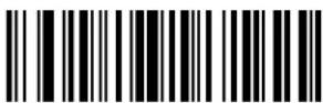
Pad Spaces To Length 20
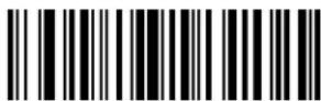
Pad Spaces To Length 21
Pad Data with Spaces (continued)

Pad Spaces To Length 23
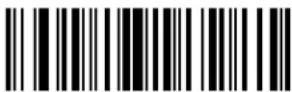
Pad Spaces To Length 22

Pad Spaces To Length 24

Pad Spaces To Length 25

Pad Spaces To Length 26

Pad Spaces To Length 27

Pad Spaces To Length 28
Pad Data with Spaces (continued)

Pad Spaces To Length 29

Pad Spaces To Length 30

Stop Pad Spaces
Pad Data with Zeros
To pad data to the left, scan the bar code containing the desired number of zeros. Send commands activate this parameter.

Pad Zeros To Length 1

Pad Zeros To Length 2

Pad Zeros To Length 3
Pad Data with Zeros (continued)
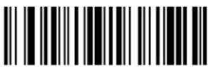
Pad Zeros To Length 4
Pad Zeros To Length 5

Pad Zeros To Length 6

Pad Zeros To Length 7

Pad Zeros To Length 8
Pad Zeros To Length 9

Pad Zeros To Length 10
Pad Data with Zeros (continued)

Pad Zeros To Length 11

Pad Zeros To Length 12
Pad Zeros To Length 13

Pad Zeros To Length 14

Pad Zeros To Length 15

Pad Zeros To Length 16

Pad Zeros To Length 17
Pad Data with Zeros (continued)

Pad Zeros To Length 18

Pad Zeros To Length 19
Pad Zeros To Length 20

Pad Zeros To Length 21

Pad Zeros To Length 22

Pad Zeros To Length 23

Pad Zeros To Length 24
Pad Data with Zeros (continued)
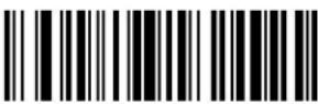
Pad Zeros To Length 25

Pad Zeros To Length 26

Pad Zeros To Length 27

Pad Zeros To Length 28

Pad Zeros To Length 29
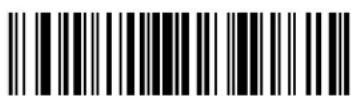
Pad Zeros To Length 30

Stop Pad Zeros
Beeps
Select a beep sequence for each ADF rule.
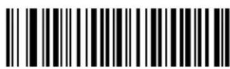
Beep Once

Beep Twice
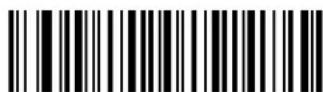
Beep Three Times
Send Keystroke (Control Characters and Keyboard Characters)
Control Characters
Scan a Send bar code for the keystroke to send.

Send Control 2
Send Control A
Send Control B
Control Characters (continued)


Send Control I
Control Characters (continued)

Send Control J

Send Control K

Send Control L
Send Control M
Send Control N

Send Control O
Send Control P
Control Characters (continued)

Send Control W
Control Characters (continued)

Send Control X

Send Control Y
Send Control Z

Send Control [

Send Control \

Send Control ]
Control Characters (continued)
Send Control 6

Send Control -
Keyboard Characters
Scan a Send bar code for the keyboard characters to send.

Send Space

Send!
Send "
Send #
Keyboard Characters (continued)

Send \$

Send %

Send &

Send '

Send (

Send )
Send *
Keyboard Characters (continued)

Send 1
Keyboard Characters (continued)

Send 2

Send 3

Send 4
Send 5

Send 6

Send 7

Send 8
Keyboard Characters (continued)


Send ?
Keyboard Characters (continued)
Send @

Send A

Send B

Send C

Send D

Send E
Send F
Keyboard Characters (continued)


Send M
Keyboard Characters (continued)
Send N

Send O

Send P

Send Q

Send R

Send S

Send T
Keyboard Characters (continued)


Send [
Keyboard Characters (continued)

Send \

Send ]
Send ^

Send _

Send
Send a

Send b
Keyboard Characters (continued)
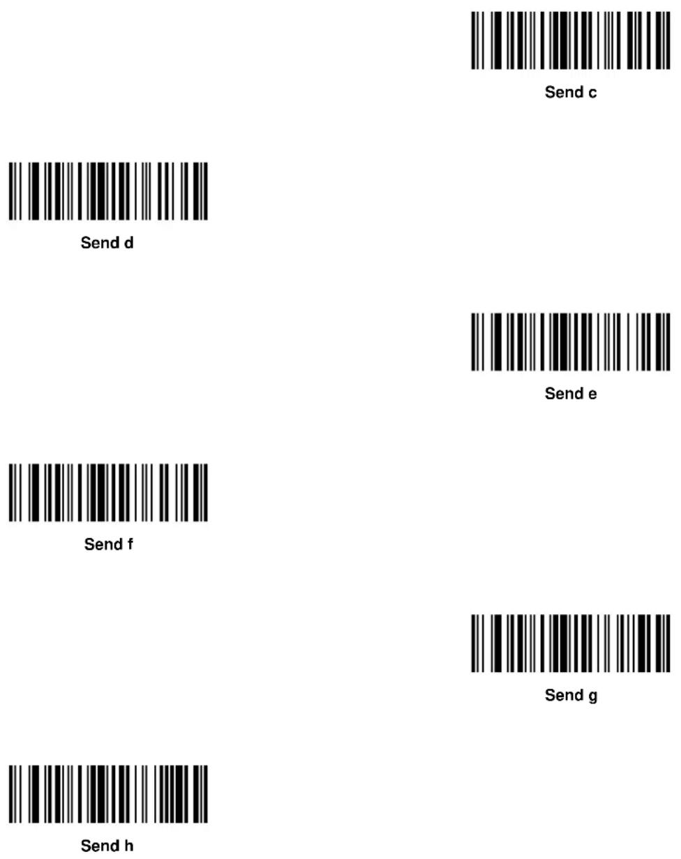

Send i
Keyboard Characters (continued)

Send j

Send k

Send I
Send m

Send n
Send o

Send p
Keyboard Characters (continued)


Send w
Keyboard Characters (continued)
Send x

Send y

Send z

Send {

Send |

Send }

Send \~
Send ALT Characters
Send Alt 2

Send Alt A

Send Alt B

Send Alt C

Send Alt D

Send Alt E

Send Alt F
Send ALT Characters (continued)

Send Alt H

Send Alt G

Send Alt I

Send Alt J

Send Alt K
Send Alt L

Send Alt M
Send ALT Characters (continued)
Send Alt N

Send Alt O

Send Alt P

Send Alt Q

Send Alt R
Send Alt S

Send Alt T
Send ALT Characters (continued)
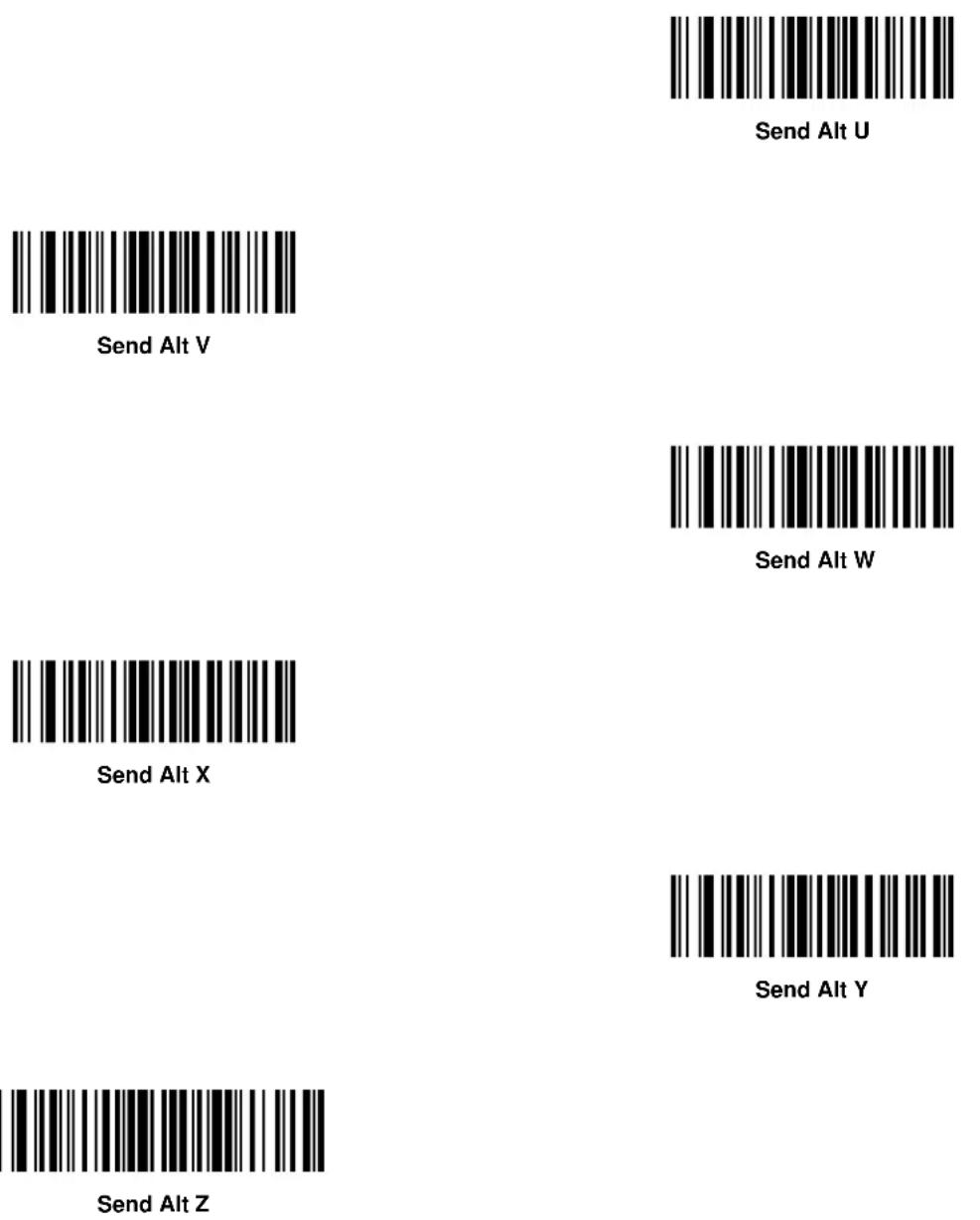

Send Alt [
Send ALT Characters (continued)
Send Alt \
Send Alt ]
Send Keypad Characters
Send Keypad *
Send Keypad +

Send Keypad -

Send Keypad.
Send Keypad /

Send Keypad 0
Send Keypad 1
Send Keypad Characters (continued)

Send Keypad 2

Send Keypad 3

Send Keypad 4

Send Keypad 5

Send Keypad 6

Send Keypad 7
Send Keypad 8
Send Keypad Characters (continued)

Send Keypad 9

Send Keypad Enter
Send Keypad Numlock

Send Break Key

Send Delete Key
Send Page Up Key
Send End Key
Send Keypad Characters (continued)

Send Page Down Key

Send Pause Key

Send Scroll Lock Key

Send Backspace Key

Send Tab Key
Send Print Screen Key

Send Insert Key
Send Keypad Characters (continued)

Send Home Key

Send Enter Key

Send Escape Key

Send Up Arrow Key

Send Down Arrow Key

Send Left Arrow Key

Send Right Arrow Key
Send Function Key
Send F1 Key

Send F2 Key

Send F3 Key

Send F4 Key
Send F5 Key
Send F6 Key

Send F7 Key
Send Function Key (continued)

Send F14 Key
Send Function Key (continued)

Send F15 Key

Send F16 Key

Send F17 Key
Send F18 Key

Send F19 Key

Send F20 Key

Send F21 Key
Send Function Key (continued)


Send PF4 Key
Send Function Key (continued)

Send PF5 Key

Send PF6 Key

Send PF7 Key

Send PF8 Key

Send PF9 Key

Send PF10 Key

Send PF11 Key
Send Function Key (continued)

Send Function Key (continued)

Send PF19 Key

Send PF20 Key

Send PF21 Key
Send PF22 Key

Send PF23 Key
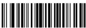
Send PF24 Key

Send PF25 Key
Send Function Key (continued)

Send Right Control Key
The "Send Right Control Key" action will send a tap (press and release) of the Right Control Key.

Send Right Control Key
Send Graphic User Interface (GUI) Characters
The Send Graphic User Interface Character actions tap the specified key while holding the System Dependent Graphic User Interface (GUI) Key. The definition of the Graphic User Interface key depends on the attached system:

Send GUI 0

Send GUI 1

Send GUI 2
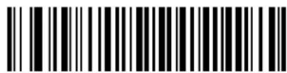
Send GUI 3

Send GUI 4
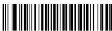
Send GUI 5
Send Graphic User Interface (GUI) Characters (continued)

Send GUI 6

Send GUI 7

Send GUI 8

Send GUI 9

Send GUI A

Send GUI B

Send GUI C
Send Graphic User Interface (GUI) Characters (continued)
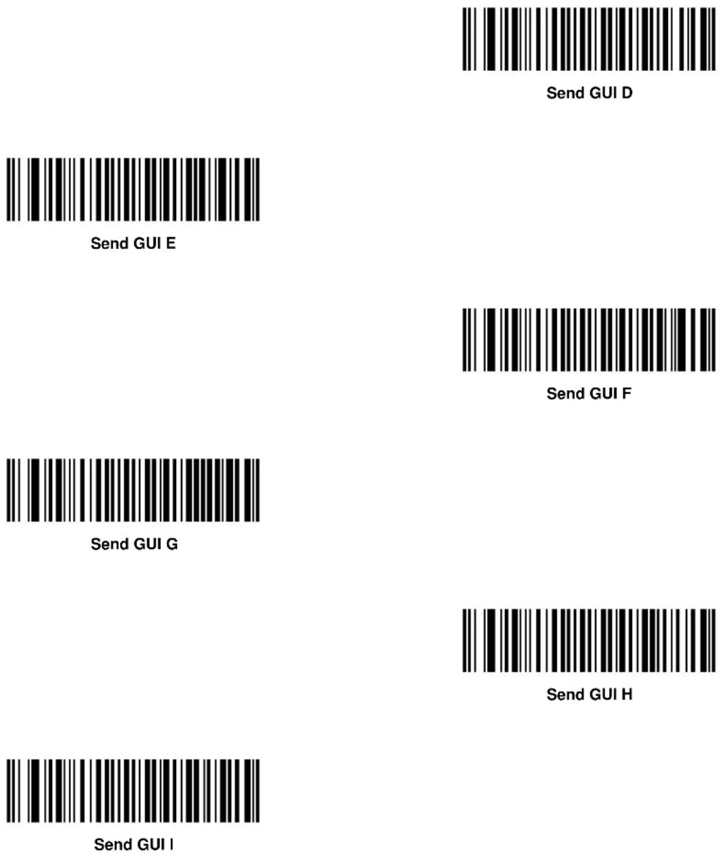

Send GUI J
Send Graphic User Interface (GUI) Characters (continued)

Send GUI K

Send GUI L

Send GUI M

Send GUI N
Send GUI O

Send GUI P

Send GUI Q
Send Graphic User Interface (GUI) Characters (continued)


Send GUI X
Send Graphic User Interface (GUI) Characters (continued)

Send GUI Y
Send GUI Z
Turn On/Off Rule Sets
Use these bar codes to turn rule sets on and off.
Turn On Rule Set 1

Turn On Rule Set 2

Turn On Rule Set 3
Turn On Rule Set 4
Turn On/Off Rule Sets (continued)
Use these bar codes to turn rule sets on and off.

Turn Off Rule Set 1
Turn Off Rule Set 2

Turn Off Rule Set 3

Turn Off Rule Set 4
Alphanumeric Keyboard

Space


\$

%
*

+

(Dash)
Alphanumeric Keyboard (continued)
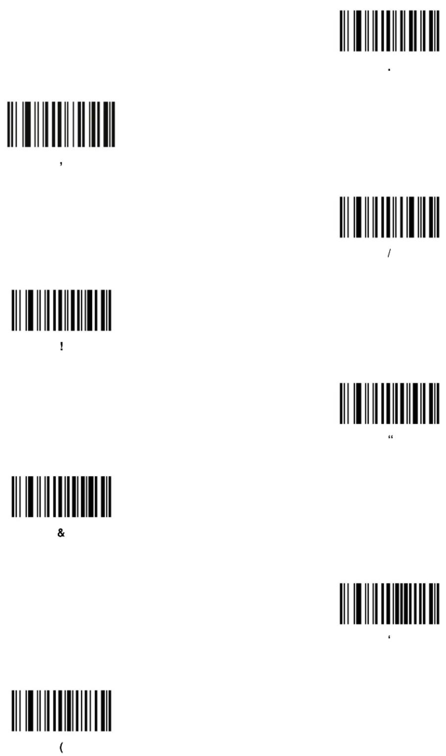
Alphanumeric Keyboard (continued)


Alphanumeric Keyboard (continued)
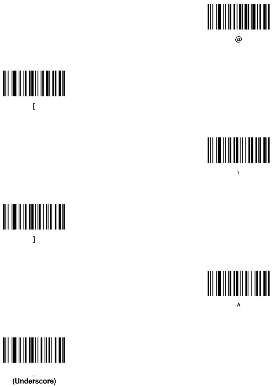

、
Alphanumeric Keyboard (continued)

NOTE Do not confuse numeric bar codes with those on the numeric keypad
0
1
2
3

4
5
Alphanumeric Keyboard (continued)

6

7

8
9

A
B

C
Alphanumeric Keyboard (continued)

Alphanumeric Keyboard (continued)

K

L
M

N
0
P

Q
Alphanumeric Keyboard (continued)

Alphanumeric Keyboard (continued)

Y

Z

Cancel
End of Message
a

b

C
Alphanumeric Keyboard (continued)

Alphanumeric Keyboard (continued)
k
|

m
n

0
p

q
Alphanumeric Keyboard (continued)

Alphanumeric Keyboard (continued)


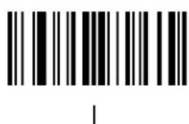


13 - 102Symbol MiniScan MSXX07 Series Integration Guide
Chapter 14 Mounting Template
Introduction
This chapter provides mounting templates for the MiniScan scanners. Copy the page with your MiniScan model's template to aid in mounting.
Symbol MS1207FZY/MS1207WA/MS2207/MS2207VHD Mounting Template


Figure 14-1 Symbol MS1207FZY/MS1207WA/MS2207/MS2207VHD Mounting Template
Symbol MS3207 Mounting Template


Figure 14-2 Symbol MS3207 Mounting Template
Appendix A ASCII Character Sets
RS-232 ASCII Character Set
Assign the values in Table A-1 as prefixes or suffixes for ASCII character data transmission in an RS-232 environment.
Table A-1 Prefix/Suffix Values
| Prefix/Suffix Value | Full ASCII Code 39 Encode Character | ASCII Character |
| 1000 %U NUL | ||
| 1001 A SOH | ||
| 1002B STX | ||
| 1003 C ETX | ||
| 1004D EOT | ||
| 1005 E ENQ | ||
| 1006F ACK | ||
| 1007 G BELL | ||
| 1008H BACKSPACE | ||
| 1009 I HORIZONTAL TAB | ||
| 1010J LF/NEW LINE | ||
| 1011 K VT | ||
| 1012L FF | ||
| 1013 M CR/ENTER | ||
| 1014N SO | ||
| 1015 O SI | ||
| 1016P DLE | ||
| 1017 Q DC1 | ||
| 1018R DC2 | ||
| 1019 S DC3 | ||
| 1020T DC4 | ||
| 1021 U NAK | ||
| 1022V SYN | ||
| 1023 W ETB | ||
| 1024X CAN | ||
| 1025 Y EM | ||
| 1026Z SUB | ||
| 1027 %A ESC | ||
| 1028 %B FS | ||
| 1029 %C GS | ||
| 1030 %D RS | ||
| 1031 %E US | ||
| 1032 Space Space | ||
| 1033 /A ! | ||
| 1034 /B " | ||
| 1035 /C # | ||
| 1036 /D $ | ||
| 1037 /E % | ||
| 1038 /F & | ||
| 1039 /G ' | ||
| 1040 /H ( | ||
| 1041 /I ) | ||
| 1042 /J | * | |
| 1043 /K + | ||
| 1044 /L | , | |
| 1045 -- | ||
| 1046 .. | ||
| 1047 /O / | ||
| 1048 0 0 | ||
| 1049 1 1 | ||
| 1050 2 2 | ||
| 1051 3 3 | ||
| 1052 4 4 | ||
| 1053 5 5 | ||
| 1054 6 6 | ||
| 1055 7 7 | ||
| 1056 8 8 | ||
| 1057 9 9 | ||
| 1058 /Z : | ||
| 1059 %F ; | ||
| 1060 %G < | ||
| 1061 %H = | ||
| 1062 %I > | ||
| 1063 %J ? | ||
| 1064 %V @ | ||
| 1065 A A | ||
| 1066 B B | ||
| 1067 C C | ||
| 1068 D D | ||
| 1069 E E | ||
| 1070 F F | ||
| 1071 G | G | |
| 1072 H H | ||
| 1073 I I | ||
| 1074 J J | ||
| 1075 K K | ||
| 1076 L L | ||
| 1077 M M | ||
| 1078 N N | ||
| 1079 O O | ||
| 1080 P P | ||
| 1081 Q Q | ||
| 1082 R R | ||
| 1083 S S | ||
| 1084 T T | ||
| 1085 U U | ||
| 1086 V V | ||
| 1087 W W | ||
| 1088 X X | ||
| 1089 Y Y | ||
| 1090 Z Z | ||
| 1091 %K [ | ||
| 1092 %L \ | ||
| 1093 %M ] | ||
| 1094 %N ^ | ||
| 1095 %O _ | ||
| 1096 %W ^ | ||
| 1097 +A | a | |
| 1098 +B | b | |
| 1099 +C | c | |
| 1100 | +D | d |
| 1101 | +E | e |
| 1102 | +F | f |
| 1103 +G g | ||
| 1104 +H h | ||
| 1105 +I i | ||
| 1106 +J j | ||
| 1107 +K k | ||
| 1108 +L l | ||
| 1109 +M m | ||
| 1110+Nn | ||
| 1111 +O o | ||
| 1112+P p | ||
| 1113+Q q | ||
| 1114+R r | ||
| 1115+S s | ||
| 1116+T t | ||
| 1117+U u | ||
| 1118+V v | ||
| 1119+W w | ||
| 1120+X x | ||
| 1121+Y y | ||
| 1122+Z z | ||
| 1123 %P { | ||
| 1124 %Q | | | |
| 1125 %R | } | |
| 1126 %S ~ | ||
| 1127 | Undefined | |
| 7013 | ENTER |
USB ASCII Character Set
Use the values in Table A-2 for ASCII character data transmission in a USB environment.
Table A-2 USB ASCII Character Set
| Prefix/ Suffix Value | Full ASCII Code 39 Encode Char. | Keystroke |
| 1000 %U CTRL 2 | ||
| 1001 A CTRL A | ||
| 1002B CTRL B | ||
| 1003 C CTRL C | ||
| 1004D CTRL D | ||
| 1005 E CTRL E | ||
| 1006F CTRL F | ||
| 1007 G CTRL G | ||
| 1008H | CTRL H / BACKSPACE* | |
| 1009 I | CTRL I / HORIZONTAL TAB* | |
| 1010J CTRL J | ||
| 1011 K CTRL K | ||
| 1012L CTRL L | ||
| 1013 M | CTRL M / ENTER* | |
| 1014N CTRL N | ||
| 1015 O CTRL O | ||
| 1016P CTRL P | ||
| 1017 Q CTRL Q | ||
| 1018R CTRL R | ||
| 1019 S CTRL S | ||
| 1020T CTRL T | ||
| 1021 U CTRL U | ||
| 1022V CTRL V | ||
| 1023 W CTRL W | ||
| 1024X CTRL X | ||
| 1025 Y CTRL Y | ||
| 1026Z CTRL Z | ||
| 1027 %A CTRL [/ | ESC* | |
| 1028 %B CTRL \ | ||
| 1029 %C CTRL ] | ||
| 1030 %D CTRL 6 | ||
| 1031 %E CTRL - | ||
| 1032 Space Space | ||
| 1033 /A ! | ||
| 1034 /B " | ||
| 1035 /C # | ||
| 1036 /D $ | ||
| 1037 /E % | ||
| 1038 /F & | ||
| 1039 /G ' | ||
| 1040 /H ( | ||
| 1041 /I ) | ||
| 1042 /J * | ||
| 1043 /K + | ||
| 1044 /L , | ||
| 1045 -- | ||
| 1046 . | . | |
| 1047 /o / | ||
| 1048 0 0 | ||
| 1049 1 1 | ||
| 1050 2 2 | ||
| 1051 3 3 | ||
| 1052 4 4 | ||
| 1053 5 5 | ||
| 1054 6 6 | ||
| 1055 7 7 | ||
| 1056 8 8 | ||
| 1057 9 9 | ||
| 1058 /Z : | ||
| 1059 %F ; | ||
| 1060 %G < | ||
| 1061 %H = | ||
| 1062 %I > | ||
| 1063 %J ? | ||
| 1064 %V @ | ||
| 1065 A A | ||
| 1066 B B | ||
| 1067 C C | ||
| 1068 D D | ||
| 1069 E E | ||
| 1070 F F | ||
| 1071 G G | ||
| 1072 H H | ||
| 1073 I I | ||
| 1074 J J | ||
| 1075 K K | ||
| 1076 L L | ||
| 1077 M | M | |
| 1078 N N | ||
| 1079 O O | ||
| 1080 P P | ||
| 1081 Q Q | ||
| 1082 R R | ||
| 1083 S S | ||
| 1084 T T | ||
| 1085 U U | ||
| 1086 V V | ||
| 1087 W W | ||
| 1088 X X | ||
| 1089 Y Y | ||
| 1090 Z Z | ||
| 1091 %K [ | ||
| 1092 %L \ | ||
| 1093 %M ] | ||
| 1094 %N ^ | ||
| 1095 %O _ | ||
| 1096 %W ` | ||
| 1097 +A a | ||
| 1098 +B b | ||
| 1099 +C c | ||
| 1100 | +D d | |
| 1101 | +E e | |
| 1102 | +F | f |
| 1103 | +G | g |
| 1104 | +H h | |
| 1105 | +I | i |
| 1106 | +J | j |
| 1107 | +K k | |
| 1108 | +L | l |
| 1109 +M m | ||
| 1110 +Nn | ||
| 1111 +Oo | ||
| 1112 +Pp | ||
| 1113 +Qq | ||
| 1114 +Rr | ||
| 1115 +Ss | ||
| 1116 +Tt | ||
| 1117 +Uu | ||
| 1118 +Vv | ||
| 1119 +Ww | ||
| 1120 +X x | ||
| 1121 +Y y | ||
| 1122 +Z z | ||
| 1123 %P { | ||
| 1124 %Q | | ||
| 1125 %R } | ||
| 1126 %S ~ | ||
| ALT Keys Keystroke | ||
| 2064 | ALT 2 | |
| 2065 | ALT A | |
| 2066 | ALT B | |
| 2067 | ALT C | |
| 2068 | ALT D | |
| 2069 | ALT E | |
| 2070 | ALT F | |
| 2071 | ALT G | |
| 2072 | ALT H | |
| 2073 ALT I | ||
| 2074 ALT J | ||
| 2075 ALT K | ||
| 2076 ALT L | ||
| 2077 ALT M | ||
| 2078 ALT N | ||
| 2079 ALT O | ||
| 2080 ALT P | ||
| 2081 ALT Q | ||
| 2082 ALT R | ||
| 2083 ALT S | ||
| 2084 ALT T | ||
| 2085 ALT U | ||
| 2086 ALT V | ||
| 2087 ALT W | ||
| 2088 ALT X | ||
| 2089 ALT Y | ||
| 2090 ALT Z | ||
| GUI Shift KeysThe AppleTM iMac keyboard has an apple key on either side of the space bar. Windows-based systems have a GUI key to the left of the left ALT key, and to the right of the right ALT key. | ||
| Other Value Keystroke | ||
| 3000 Right Control Key | ||
| 3048 GUI 0 | ||
| 3049 GUI 1 | ||
| 3050 GUI 2 | ||
| 3051 GUI 3 | ||
| 3052 GUI 4 | ||
| 3053 GUI 5 | ||
| *The keystroke in bold is sent only if Function Key Mapping is enabled. | ||
| 3054 GUI 6 | ||
| 3055 GUI 7 | ||
| 3056 GUI 8 | ||
| 3057 GUI 9 | ||
| 3065 GUI A | ||
| 3066 GUI B | ||
| 3067 GUI C | ||
| 3068 GUI D | ||
| 3069 GUI E | ||
| 3070 GUI F | ||
| 3071 GUI G | ||
| 3072 GUI H | ||
| 3073 GUI I | ||
| 3074 GUI J | ||
| 3075 GUI K | ||
| 3076 GUI L | ||
| 3077 GUI M | ||
| 3078 GUI N | ||
| 3079 GUI O | ||
| 3080 GUI P | ||
| 3081 GUI Q | ||
| 3082 GUI R | ||
| 3083 GUI S | ||
| 3084 GUI T | ||
| 3085 GUI U | ||
| 3086 GUI V | ||
| 3087 GUI W | ||
| 3088 GUI X | ||
| 3089 GUI Y | ||
| 3090 GUI Z | ||
| F Keys Keystroke | ||
| 5001 F1 | ||
| 5002 F2 | ||
| 5003 F3 | ||
| 5004 F4 | ||
| 5005 F5 | ||
| 5006 F6 | ||
| 5007 F7 | ||
| 5008 F8 | ||
| 5009 F9 | ||
| 5010 F10 | ||
| 5011 F11 | ||
| 5012 F12 | ||
| 5013 F13 | ||
| 5014 F14 | ||
| 5015 F15 | ||
| 5016 F16 | ||
| 5017 F17 | ||
| 5018 F18 | ||
| 5019 F19 | ||
| 5020 F20 | ||
| 5021 F21 | ||
| 5022 F22 | ||
| 5023 F23 | ||
| 5024 F24 | ||
| Keypad Keystroke | ||
| 6042 * | ||
| 6043 + | ||
| 6044 undefined | ||
| 6045 - | ||
| 6046 . | ||
| 6047 / | ||
| 6048 0 | ||
| 6049 1 | ||
| 6050 2 | ||
| 6051 3 | ||
| 6052 4 | ||
| 6053 5 | ||
| 6054 6 | ||
| 6055 7 | ||
| 6056 8 | ||
| 6057 9 | ||
| 6058 Enter | ||
| 6059 Num Lock | ||
| Extended Keypad Keystroke | ||
| 7001 Break | ||
| 7002 Delete | ||
| 7003 PgUp | ||
| 7004 End | ||
| 7005 Pg Dn | ||
| 7006 Pause | ||
| 7007 Scroll Lock | ||
| 7008 Backspace | ||
| 7009 Tab | ||
| 7010 Print Screen | ||
| 7011 Insert | ||
| 7012 Home | ||
| 7013 Enter | ||
| 7014 Escape | ||
| 7015 Up Arrow | ||
| 7016 Down Arrow | ||
| 7017 Left Arrow | ||
| 7018 Right Arrow | ||
| *The keystroke in bold is sent only if Function Key Mapping is enabled. | ||
A - 16 Symbol MiniScan MSXX07 Series Integration Guide
Glossary
A
AIM. Automatic Identification Manufacturers, Inc. is the trade association for manufacturers of automatic identification systems.
Alphanumeric. A character set that contains letters, numbers and other characters such as special symbols.
Aperture. The opening in an optical system defined by a lens or baffle that establishes the field of view.
ASCII. American Standard Code for Information Interchange. A 7 bit-plus-parity code representing 128 letters, numerals, punctuation marks and control characters. It is a standard data transmission code in the U.S.
Aspect Ratio. The ratio of symbol height to symbol length in a 2-dimensional symbol.
Autodiscrimination. The ability of an interface controller to determine the code type of a scanned bar code. After this determination is made, the information content is decoded.
Automatic Identification System. The application of various technologies, such as bar code recognition, image recognition, voice recognition and RF/MW transponders, for the purpose of data entry into a data processing system and bypassing the key-entry component of traditional data entry.
B
Background. The area surrounding a printed symbol including the spaces and quiet zones.
Bar. The dark element in a printed bar code symbol.
Bar Code. A pattern of variable-width bars and spaces which represents numeric or alphanumeric data in machine-readable form. The general format of a bar code symbol consists of a leading margin, start character, data or message character, check character (if any), stop character, and trailing margin. Within this framework, each recognizable symbology uses its own unique format. See Symbology.
Bar Code Character. A single group of bars and spaces which represent an individual number, letter, punctuation mark or other symbol.
Bar Code Density. The number of characters represented per unit of measurement (e.g., characters per inch).
Bar Code Reader. A device used to read or decode a bar code symbol.
Bar Code Symbol. The combination of symbol characters and features required by a particular symbology, including quiet zones, start and stop characters, data characters, check characters and other auxiliary patterns, that together form a complete scannable entity. See Symbol.
Bar Height. The dimension of a bar measured perpendicular to the bar width.
Bar Width. Thickness of a bar measured from the edge closest to the symbol start character to the trailing edge of the same bar.
Baud Rate. A measure of the data flow or number of signaling events occurring per second. When one bit is the standard "event," this is a measure of bits per second (bps). For example, a baud rate of 50 means transmission of 50 bits of data per second.
Bi-directional. Denotes that a machine-readable symbol can be read successfully in two directions – either backwards or forwards. Also identifies a scanner that can operate or a bar code that can be read independent of scanning direction.
Binary. Denotes a numbering system to base 2 in which numbers are expressed as combinations of the digits 0 and 1 with positional weighting based on powers of 2. In computing, these can be represented electrically by 'off' and 'on' respectively or in machine-readable symbols by narrow and wide elements or by the absence or presence of a bar module.
Bit. Binary digit. One bit is the basic unit of binary information. Generally, eight consecutive bits compose one byte of data. The pattern of 0 and 1 values within the byte determines its meaning.
Bits per Second (bps). Bits transmitted or received.
bps. See Bits Per Second.
Byte. On an addressable boundary, eight adjacent binary digits (0 and 1) combined in a pattern to represent a specific character or numeric value. Bits are numbered from the right, 0 through 7, with bit 0 the low-order bit. One byte in memory is used to store one ASCII character.
or
A sequential series of bits comprising one character and handled as one unit. Usually encoded in the ASCII format, a byte usually consists of eight bits and represents one alphabetic or special character, two decimal digits or eight binary bits.
C
CDRH. Center for Devices and Radiological Health. A federal agency responsible for regulating laser product safety. This agency specifies various laser operation classes based on power output during operation.
CDRH Class 1. This is the lowest power CDRH laser classification. CDRH Class 1 devices are safe under reasonably foreseeable conditions of operation. Software and other controls to limit exposure to laser light may be required to achieve CDRH Class 1 operation. The CDRH time base for Class 1 devices is 10,000 seconds.
CDRH Class 2. CDRH Class II devices may not emit more than 1 milliwatt average radiant power. Eye protection for CDRH Class II devices is normally afforded by aversion responses, including the blink reflex.
Character. A pattern of bars and spaces which either directly represents data or indicates a control function, such as a number, letter, punctuation mark, or communications control contained in a message.
Character Set. Those characters available for encoding in a particular bar code symbology.
Check Digit. A digit used to verify a correct symbol decode. The scanner inserts the decoded data into an arithmetic formula and checks that the resulting number matches the encoded check digit. Check digits are required for UPC but are optional for other symbologies. Using check digits decreases the chance of substitution errors when a symbol is decoded.
Codabar. A discrete self-checking code with a character set consisting of digits 0 to 9 and six additional characters: (- \$ : / , +).
Code. A set of unambiguous rules specifying the way in which data may be represented as numbers and letters used to represent information. See Number System.
Code 128. A high density symbology which allows the controller to encode all 128 ASCII characters without adding extra symbol elements.
Code 3 of 9 (Code 39). A versatile and widely used alphanumeric bar code symbology with a set of 43 character types, including all uppercase letters, numerals from 0 to 9 and 7 special characters (- . / + % \$ and space). The code name is derived from the fact that 3 of 9 elements representing a character are wide, while the remaining 6 are narrow.
Code 93. An industrial symbology compatible with Code 39 but offering a full character ASCII set and a higher coding density than Code 39.
Code Length. Number of data characters in a bar code between the start and stop characters, not including those characters.
Codeword. As a symbol character value, this is an intermediate level of coding between source data and the graphical encoding in the symbol.
COM port. Communication port; ports are identified by number, e.g., COM1, COM2.
Concatination. The construction of a string of data from two or more strings by appending each string in succession. The linking or chaining together of separate items of data in a bar code symbol or of the data contained in two or more separate bar code symbols (also referred to as message append and structured append).
Continuous Code. A bar code or symbol in which all spaces within the symbol are parts of characters. There are no intercharacter gaps in a continuous code. The absence of gaps allows for greater information density.
Contrast. The difference in reflectance between the black and white (or bar and space) areas of a symbol.
D
Data Identifier. A specified character or string of characters that defines the intended use of the data element that follows. For the purposes of automatic data capture technologies, data identifier refers to the alphanumeric identifiers as defined in ANSI MH10.8.2, formerly known as ANSI/FACT data identifiers.
Data Matrix. This error correcting, 2-dimensional matrix symbology was originally developed in 1989, and a finalized design was completed in 1995 by International Data Matrix. It's capable of encoding various character sets including strictly numeric data, alphanumeric data and all ISO 646 (ASCII) characters, as well as special character sets. The symbology has both error detection and error correction features. Each Data Matrix symbol consists of data regions, which contain nominally square modules set out in a regular array. A dark module is a binary 1 and a light module is a binary 0. There is no specified minimum or maximum for the X or Y dimension. The data region is surrounded by a finder pattern, a perimeter to the data region that is 1 module wide, which is surrounded by a quiet zone on all four sides of the symbol. Two adjacent sides are solid dark lines used primarily to define physical size, orientation and symbol distortion. The two opposite sides consist of alternating dark and light modules. These are used primarily to define the cell structure but also assist in determining physical size and distortion. There are 2 types of Data Matrix symbologies: ECC 000 - 140 with several available levels of convolutional error correction, and ECC 200, which uses Reed-Solomon error correction. For ISO/IEC JTC 1/SC 31 purposes, only ECC 200 is recommended. The intellectual property rights associated with Data Matrix have been committed to the public domain.
Data Structure. The stipulation of the type of information that is included in a bar code, such as its order and format.
Dead Zone. An area within a scanner's field of view, in which specular reflection may prevent a successful decode.
Decode. To recognize a bar code symbology (e.g., UPC/EAN) and then analyze the content of the specific bar code scanned.
Decode Algorithm. A decoding scheme that converts pulse widths into data representation of the letters or numbers encoded within a bar code symbol.
Decoder. An electronic package that receives the signals from the scanning function, performs the algorithm to interpret the signals into meaningful data and provides the interface to other devices.
Decryption. Decryption is the decoding and unscrambling of received encrypted data. Also see, Encryption and Key.
Depth of Field. The range between minimum and maximum distances at which a scanner can read a symbol with a certain minimum element width.
Diffuse Reflection. The component of reflected light that emanates in all directions from the reflecting surface.
Discrete 2 of 5. A binary bar code symbology representing each character by a group of five bars, two of which are wide. The location of wide bars in the group determines which character is encoded; spaces are insignificant. Only numeric characters (0 to 9) and START/STOP characters may be encoded.
Discrete Code. A bar code or symbol in which the spaces between characters (intercharacter gaps) are not part of the code.
DRAM. Dynamic random access memory.
E
EAN. European Article Number. This European/International version of the UPC provides its own coding format and symbology standards. Element dimensions are specified metrically. EAN is used primarily in retail.
EAN/UPC. A fixed-length, numeric 13-digit bar code symbol consisting of 30 dark elements and 29 intervening light elements. Each character is represented by 2 bars and 2 spaces over 7 modules. A bar may be comprised of 1, 2, 3 or 4 modules. Each EAN/U.P.C. symbol consists of a leading quiet zone, a start pattern, 7 left-hand data characters, a center bar pattern, 5 right-hand data characters, a Modulo 10 check character, a stop pattern and a trailing quiet zone.
U.P.C. is often considered a 12-digit code. The 13th digit of EAN/U.P.C. symbol is a derived character in the left-most position. In the case of U.P.C., this derived left-most character is a 0.
Element. Generic term for a bar or space.
Encoded Area. Total linear dimension occupied by all characters of a code pattern, including start/stop characters and data.
ENQ (RS-232). ENQ software handshaking is also supported for the data sent to the host.
Error Correction. A reader or decoder's use of mathematical schemes to reconstruct or replace damaged or missing symbol characters to enable the reading of the symbol data.
Error-Correction Characters. Symbol characters used for error correction and detection, calculated automatically from the other symbol characters.
Error-Correction Level. An indicator of the number of characters used in a symbology for error correction. A higher level of error correction allows for correcting greater potential symbol damage.
Error Detection. This occurs when error-correction characters detect that the presence of errors in the symbol exceeds the error correction capacity, and keeps the symbol from being decoded as erroneous data.
Error-Detection Characters. Symbol characters reserved for error detection that are calculated automatically from the other symbol characters.
ESD. Electro-Static Discharge
F
Fixed Beam Bar Code Reader. A scanning device where scanning motion is achieved by moving the object relative to the reader; as opposed to a moving beam reader.
G
GS1 DataBar. Formerly Reduced Space Symbology (RSS): A family of space efficient symbologies developed by UCC.EAN.
Guard Bars. Bars located at both ends and the center of a UPC and EAN symbol to provide reference points for scanning.
H
Horizontal Bar Code. A bar code or symbol with an overall length dimension that is parallel to the horizon, which resembles a picket fence.
Host Computer. A computer that serves other terminals in a network, providing such services as computation, database access, supervisory programs and network control.
Hz. Hertz; A unit of frequency equal to one cycle per second.
|
IEC. International Electrotechnical Commission. This international agency regulates laser safety by specifying various laser operation classes based on power output during operation.
IEC (825) Class 1. This is the lowest power IEC laser classification. IEC Class 1 devices are safe under reasonably foreseeable conditions of operation. Software and other controls to limit exposure to laser light may be required to achieve IEC Class 1 operation. The IEC time base for Class 1 devices is 100 seconds if intentional viewing of laser light is not required in the design or function of the device. The IEC time base for Class 1 devices is 30,000 seconds where intentional viewing of laser light is inherent in the design or function of the device.
Input/Output Ports. I/O ports are primarily dedicated to passing information into or out of the terminal memory. Series 9000 mobile computers include Serial and USB ports.
Intercharacter Gap. The space between two adjacent bar code characters in a discrete code.
Interleaved 2 of 5. A binary bar code symbology representing character pairs in groups of five bars and five interleaved spaces. Interleaving provides for greater information density. The location of wide elements (bar/spaces) within each group determines which characters are encoded. This continuous code type uses no intercharacter spaces. Only numeric (0 to 9) and START/STOP characters may be encoded.
Interleaved Bar Code. A bar code in which characters are paired together, using bars to represent the first character and the intervening spaces to represent the second.
I/O Ports. interface The connection between two devices, defined by common physical characteristics, signal characteristics, and signal meanings. Types of interfaces include RS-232 and PCMCIA.
K
Key. A key is the specific code used by the algorithm to encrypt or decrypt the data. Also see, Encryption and Decrypting.
L
LASER. Light Amplification by Stimulated Emission of Radiation. The laser is an intense light source. Light from a laser is all the same frequency, unlike the output of an incandescent bulb. Laser light is typically coherent and has a high energy density.
Laser Diode. A gallium-arsenide semiconductor type of laser connected to a power source to generate a laser beam. This laser type is a compact source of coherent light.
Laser Scanner. An optical bar code reading device using a coherent laser light beam as its source of illumination.
LCD. See Liquid Crystal Display.
LED Indicator. A semiconductor diode (LED - Light Emitting Diode) used as an indicator, often in digital displays. The semiconductor uses applied voltage to produce light of a certain frequency determined by the semiconductor's particular chemical composition.
Light Emitting Diode. See LED.
Liquid Crystal Display (LCD). A display that uses liquid crystal sealed between two glass plates. The crystals are excited by precise electrical charges, causing them to reflect light outside according to their bias. They use little electricity and react relatively quickly. They require external light to reflect their information to the user.
M
Matrix Symbols. A 2-dimensional array of regular polygon shaped cells where the center-to-center distance of adjacent elements is uniform. The arrangement of the cells represents data and/or symbology functions. Matrix symbols may include recognition patterns that do not follow the same rule as the other elements within the symbol (i.e., Data Matrix and Maxicode).
MIL. 1 mil = 1 thousandth of an inch; a unit of measure often used to quantify bar code printing and scanning dimensions.
Misread (Misdecode). A condition which occurs when the data output of a reader or interface controller does not agree with the data encoded within a bar code symbol.
Module. (1) The narrowest nominal width unit of measure in a symbol. In certain symbologies, element widths are specified as multiples of 1 module. Equivalent to X dimension; or (2) a single cell in a matrix symbology used to encode 1 bit of data. In Maxicode, the module shape is a regular hexagon. In Data Matrix, the module shape is nominally square. In PDF417, the module shape is a regular rectangle. In bar code symbologies, the module shape is a regular rectangle.
Module Check Digit or Character. A character within the symbol data field calculated using modular arithmetic that is used for error detection. The calculated character is determined by applying a code algorithm to the data field contents. See Check Character.
Moving Beam Bar Code Reader. A device where scanning motion is achieved by mechanically moving the optical geometry.
MRD. Minimum reflectance difference: a formula that is used to determine if there is an adequate difference between absorbed and reflected light.
N
Nanometer. Unit of measure used to define the wavelength of light that is equal to 10-9 meter.
Nominal. The exact (or ideal) intended value for a specified parameter. Tolerances are specified as positive and negative deviations from this value.
Nominal Size. Standard size for a bar code symbol. Most UPC/EAN codes are used over a range of magnifications (e.g., from 0.80 to 2.00 of nominal).
Non-Contact Reader/Scanner. Bar code readers requiring no physical contact with the printed symbol.
Non-read. The absence of data at the scanner output after an attempted scan, which is due to no code, defective code, scanner failure or operator error.
O
Omnidirectional. Bar codes read in any orientation relative to the scanner.
Optical Throw. The distance from the scanner face to the closest point at which symbol can be read; also, optical throw is the difference between range and depth of field.
Orientation. The alignment of the symbol's scan path. Two possible orientations are horizontal with vertical bars and spaces (picket fence) and vertical with horizontal bars and spaces (ladder).
Overhead. The fixed number of characters required for start, stop and checking in a given symbol. For example, a symbol requiring a start, stop and 2 check characters contains 4 characters of overhead.
P
Parameter. A variable that can have different values assigned to it.
PDF417. An error correcting 2-dimensional multi-row symbol developed in 1992 by Symbol Technologies, PDF417 symbols are constructed from 4 bars and 4 spaces over 17 modules. The symbol size is from 3 to 90 rows. There is no specified minimum or maximum for X or Y dimension. With at least the recommended minimum level of error correction, the recommended Y dimension is 3X. With less than the minimum recommended level of error correction, the recommended Y dimension is 4X. A quiet zone of 2X is specified on each side of a symbol. Because of delta decode techniques, the symbology is immune from uniform bar width growth. PDF417 supports cross-row scanning. The intellectual property rights associated with PDF417 have been committed to the public domain.
Percent Decode. The average probability that a single scan of a bar code would result in a successful decode. In a well-designed bar code scanning system, that probability should approach near 100%.
Pitch. Rotation of a bar code symbol in an axis parallel to the direction of the bars.
Plessey Code. A pulse-width, modulated bar code commonly used for shelf marking in grocery stores.
Postnet Code. Code developed by the U.S. Postal Service to assist in the automatic sorting of mail.
Print Contrast Signal (PCS). Measurement of the contrast (brightness difference) between the bars and spaces of a symbol. A minimum PCS value is needed for a bar code symbol to be scannable. PCS = (RL - RD) / RL, where RL is the reflectance factor of the background and RD the reflectance factor of the dark bars.
Programming Mode. The state in which a scanner is configured for parameter values. See Scanning Mode.
Q
Quiet Zone. A clear space, containing no dark marks, which precedes the start character of a bar code symbol and follows the stop character.
QWERTY. A standard keyboard commonly used on North American and some European PC keyboards. "QWERTY" refers to the arrangement of keys on the left side of the third row of keys.
R
Reflectance. Amount of light returned from an illuminated surface.
Resolution. The narrowest element dimension which is distinguished by a particular reading device or printed with a particular device or method.
RS-232. An Electronic Industries Association (EIA) standard that defines the connector, connector pins, and signals used to transfer data serially from one device to another.
s
Scan Area. Area intended to contain a symbol.
Scanner. An electronic device used to scan bar code symbols and produce a digitized pattern that corresponds to the bars and spaces of the symbol. Its three main components are: 1) Light source (laser or photoelectric cell) - illuminates a bar code,; 2) Photodetector - registers the difference in reflected light (more light reflected from spaces); 3) Signal conditioning circuit - transforms optical detector output into a digitized bar pattern.
Scanning Mode. The scanner is energized, programmed and ready to read a bar code.
Scanning Sequence. A method of programming or configuring parameters for a bar code reading system by scanning bar code menus.
Self-Checking Code. A symbology that uses a checking algorithm to detect encoding errors within the characters of a bar code symbol.
Skew. Rotation of a bar code symbol on an axis parallel to the symbol's length.
Space. The lighter element of a bar code formed by the background between bars.
Space Width. The thickness of a space measured from the edge closest to the symbol start character to the trailing edge of the same space.
Specular Reflection. The mirror-like direct reflection of light from a surface, which can cause difficulty decoding a bar code.
Stacked Symbol (2-D Symbols). A 2-dimensional (2-D) symbol with sequences of linear (width-coded) data that are stacked one upon another (i.e., PDF417).
Start/Stop Character. A pattern of bars and spaces that provides the scanner with start and stop reading instructions and scanning direction. The start and stop characters are normally to the left and right margins of a horizontal code.
Substrate. A foundation material on which a substance or image is placed.
Symbol. A scannable unit that encodes data within the conventions of a certain symbology, usually including start/stop characters, quiet zones, data characters and check characters.
Symbol Aspect Ratio. The ratio of symbol height to symbol width.
Symbol Density. The number of data characters per unit length; usually expressed as characters per inch (CPI).
Symbol Height. The distance between the outside edges of the quiet zones of the first row and the last row.
Symbol Length. Length of symbol measured from the beginning of the quiet zone (margin) adjacent to the start character to the end of the quiet zone (margin) adjacent to a stop character.
Symbology. The structural rules and conventions for representing data within a particular bar code type (e.g. UPC/EAN, Code 39, PDF417, etc.).
T
Tilt. Rotation of a bar code symbol on an axis perpendicular to the substrate.
Tolerance. Allowable deviation from the nominal bar or space width.
Two-dimensional symbology. A machine-readable symbol which must be examined both vertically and horizontally to read the entire message.
A 2-dimensional (2-D) symbol may be one of two types of machine-readable symbols: a Matrix Symbol or a stacked symbol. 2-D symbols differ from linear bar codes with the ability for high data content, small size, data efficiency and error correction capability.
U
UCC. Uniform Code Council: the organization that administers the U.P.C and other retail standards.
UCC.EAN-128. Code 128 with a Function 1 character in the first position that is the symbology used with the UCC.EAN format for a universal product number (UPN).
UPC. Universal Product Code. A relatively complex numeric symbology. Each character consists of two bars and two spaces, each of which is any of four widths. The standard symbology for retail food packages in the United States.
V
Variable Length Code. A code with a number of encoded characters within a range, as opposed to a code with a fixed number of encoded characters.
Vertical Bar Code. A bar code pattern presented in such orientation that the symbol from start to stop is perpendicular to the horizon. The individual bars are in an array appearing as rungs of a ladder.
Visible Laser Diode (VLD). A solid state device which produces visible laser light.
W
Wand Scanner. A handheld scanning device used as a contact bar code or OCR reader.
Wedge. A device that plugs in between a keyboard and a terminal and allows data to be entered by a keyboard or by various types of scanners.
X
X Dimension. The dimension of the narrowest bar and narrowest space in a bar code.
Y
Y Dimension. The height of the modules in a row of a 2-dimensional (2-D) symbols.
Glossary - 12 Symbol MiniScan MSXX07 Series Integration Guide
Index
A
accessories 2-15
actions 13-2
adding window 2-12
ADF 13-1
actions....13-1, 13-25
move cursor 13-29
send data 13-25
setup fields 13-28
alphanumeric keyboard 13-88
alternate rule sets 13-3
bar code list 13-6
bar code menu example 13-2
beep 13-44
code lengths 13-16
code types 13-11
criteria 13-1, 13-11
default rules 13-5
move cursor past a character 13-28
move cursor to a character 13-28
move cursor to start of data 13-28
numeric keypad .....13-22, 13-23
pad spaces 13-35
pad zeros 13-39
rules 13-1
rules hierarchy 13-4
send alt characters 13-63
send control characters ..... 13-44
send function key 13-73
send keyboard characters ..... 13-49
send keypad characters 13-68
send preset value 13-28
send value 13-33
skip ahead "n" characters 13-28
skip ahead characters 13-30
skip back "n" characters 13-28
skip back characters 13-31
space removal 13-33
special commands 13-8
specific data string 13-20
specific string
any location 13-21
any message ok 13-21
at start 13-20
rule belongs to set 13-24
turn off rule sets 13-86, 13-87
zero removal 13-33
advanced data formatting 13-1
actions 13-1, 13-25
alphanumeric keyboard 13-88
alternate rule sets 13-3
bar code menu example 13-2
beep 13-44
code lengths 13-16
code types 13-11
criteria 13-1, 13-11
default rules 13-5
numeric keypad 13-22, 13-23
pad spaces 13-35
pad zeros 13-39
rules 13-1
rules hierarchy 13-4
send alt characters 13-63
send control characters 13-44
send function key 13-73
send keyboard characters 13-49
send keypad characters 13-68
send preset value 13-33
setup fields 13-28
skip ahead characters 13-30
skip back characters 13-31
space removal 13-33
special commands 13-8
specific data string 13-20
turn off rule sets 13-86, 13-87
zero removal 13-33
aiming modes 10-13
anti-reflection coaters 2-14
applications 1-2
fixed mount 1-2
OEM 1-2
assembling stand 2-3
B
bar codes
ADF list 13-6
data options pause duration .... 13-8
RS-232 baud rate 11-7
beep on bel 11-15
check receive errors 11-10
data bits 11-9
default table 11-2
hardware handshaking 11-10
host serial response time-out ..... 11-14
host types 11-5
intercharacter delay 11-16
parity 11-8
RTS line state 11-15
software handshaking 11-12
stop bit select 11-15
scan angle 10-10
set defaults 10-2
USB caps lock override ..... 12-8
country keyboard types 12-4
default table 12-2
device type 12-3
keystroke delay 12-7
unknown characters 12-9
beeper definitions 3-7
beeper definitions 3-7
block diagram 1-3
bracket mounting scanner 2-4
bullets .....xiv
C
code types ADF 13-11
codewords 10-85
transmit unknown 10-86
connection 2-6
via USB 2-7, 12-1
conventions notational ..... xiv
conveyor applications applications conveyor 2-10
D
decode zone MS1207FZY 4-7 MS1207WA 5-7 MS2207 6-8 MS2207VHD 7-8 MS3207 8-9
default parameters....10-2 RS-232....11-2 USB....12-2
default table 10-2
dimensions MS1207FZY 4-6 MS1207WA 5-5 MS2207 6-6 MS2207VHD 7-6 MS3207 8-7
E
ECI decoder ..... 10-87 delete character set ECIs ..... 10-87
electrical interface MS1207FZY 4-2 MS1207WA 5-2 MS2207 6-2 MS2207VHD 7-2 MS3207 8-2
escape characters 10-86
H
host types RS-232 11-5 USB 12-3
humidity MS1207FZY 4-5 MS1207WA 5-5 MS2207 6-6 MS2207VHD 7-6 MS3207 8-7
|
information, service ...... xv
installation
connecting MiniScan 2-6
location 2-7
mechanical drawing
MS1207FZY 4-3
MS1207WA 5-3
MS2207 6-3
MS2207VHD 7-3
MS3207 8-4
mounting 2-1
mounting scanner on bracket 2-4
mounting scanner on stand 2-3
mounting stand 2-3
stand 2-3
via USB 2-7, 12-1
interface pin-outs ..... 4-2, 5-2, 6-2, 7-2, 8-2
L
laser class
MS1207FZY 4-6
MS1207WA 5-5
MS2207 6-6
MS2207VHD 7-6
MS3207 8-7
laser power
MS1207FZY 4-5
MS1207WA 5-5
MS2207 6-5
MS2207VHD 7-5
MS3207 8-6
LED
definitions 3-7
M
macro PDF
delete character set ECIs 10-87
ECI decoder 10-87
escape characters ..... 10-86
last blocker marker 10-92
transmit addressee 10-90
transmit block count 10-89
transmit checksum 10-91
transmit file name 10-88
transmit filesize 10-91
transmit macro PDF control header 10-92
transmit sender 10-90
transmit symbols in codeword format ..... 10-85
transmit time stamp 10-89
transmit unknown codewords 10-86
transmit user-selected fields 10-88
maintenance 9-1
mechanical drawing
MS1207FZY 4-3
MS1207WA 5-3
MS2207 6-3
MS2207VHD 7-3
MS3207 8-4
mounting 2-1
mounting bracket 2-4
mounting template 14-1, 14-2
N
notational conventions xiv
0
operational parameters 10-1
P
parameters
operational 10-1
RS-232 11-3
USB 12-3
power requirements
MS1207FZY 4-5
MS1207WA 5-5
MS2207 6-5
MS2207VHD 7-5
MS3207 8-6
print contrast
MS1207FZY 4-5
MS1207WA 5-5
MS2207 6-5
MS2207VHD 7-5
MS3207 8-6
programming bar codes
aiming mode 10-13
beep after good decode 10-16
beeper frequency adjustment 10-9
beeper tone 10-9
beeper volume 10-8
bi-directional redundancy 10-19
cancel 10-95
Codabar 10-62
CLSI editing 10-64
enable/disable 10-62
length 10-63
NOTIS editing 10-64
Code 11 10-52
check digit verification ..... 10-54
lengths 10-53
transmit check digit 10-55
Code 128....10-39
decode performance ..... 10-41
lengths 10-40
UCC/EAN-128 10-39
Code 128 emulation .... 10-71
Code 39 10-43
check digit verification 10-46
Code 39 full ASCII 10-47
decode performance ..... 10-48
lengths 10-45
transmit check digit 10-46
Trioptic Code 39 10-43
Code 93 lengths ..... 10-51
composite CC-A/B 10-74
composite CC-C 10-74
convert GS1 DataBar to UPC/EAN ..... 10-73
delete character set ECIs 10-87
Discrete 2 of 5 lengths ..... 10-61
ECI decoder 10-87
escape characters 10-86
event reporting 10-82-10-84
boot up event 10-83
decode event 10-83
parameter event 10-84
GS1 DataBar Expanded 10-73
GS1 DataBar Limited 10-72
GS1 DataBar-14 10-72
Interleaved 2 of 5 10-56
check digit verification 10-58
convert | 2 of 5 to EAN-13 ..... 10-59
lengths 10-57
transmit check digit 10-59
ISBT 128 enable/disable 10-40
laser on time 10-10
last blocker marker 10-92
linear code type security .....10-18-10-19
linear UPC/EAN decode 10-38
MicroPDF417 10-69
performance 10-70
MSI plessey 10-65
check digit algorithm ..... 10-68
check digits 10-67
lengths 10-66
transmit check digit 10-67
numeric bar codes 10-93-??
PDF417 10-69
power mode 10-11
prefix/suffix values 10-79
programmable raster size/expansion ..... 10-14
scan data transmission format 10-80
scanning mode 10-12
set defaults 10-7
timeout between decodes ..... 10-15
transmit addressee 10-90
transmit block count 10-89
transmit checksum 10-91
transmit code ID character 10-77
transmit file name 10-88
transmit filesize 10-91
transmit macro PDF control header ..... 10-92
transmit macro PDF user-selected fields .... 10-88
transmit no read message ..... 10-16, 10-17
transmit sender 10-90
transmit symbols in codeword format ..... 10-85
transmit time stamp 10-89
transmit unknown codewords 10-86
trigger modes 10-11
UPC composite mode 10-76
UPC half block stitching 10-38
UPC/EAN 10-20
bookland EAN 10-22
bookland ISBN format 10-36
convert UPC-E to UPC-A 10-34
convert UPC-E1 to UPC-A ..... 10-34
coupon code 10-23
decode supplementals 10-24
EAN zero extend 10-35
EAN-13 10-22
EAN-8 10-21
security level 10-37
supplemental redundancy ..... 10-28
supplementals 10-25
UPC-A 10-20
UPC-A check digit 10-29
UPC-A preamble 10-31
UPC-E 10-20
UPC-E check digit 10-29
UPC-E preamble 10-32
UPC-E1 10-21
cyclone omnidirectional 3-4
high density single scan line 3-2
raster....3-1, 3-2
single scan line 3-1
scanning modes 10-12
scanning tips 3-5
service information ...... xv
setup
connecting a USB interface .....2-7, 12-1
skew, pitch and roll 4-6, 5-6, 6-7, 7-7, 8-8
stand
mounting 2-3
mounting scanner 2-3
glass 2-12
window properties 2-13
T
technical specifications
MS1207FZY 4-5
MS1207WA 5-5
MS2207 6-5
MS2207VHD 7-5
MS3207 8-6
temperature
MS1207FZY 4-5
MS1207WA 5-5
MS2207 6-6
MS2207VHD 7-6
MS3207 8-7
triggering options....3-5, 10-11
troubleshooting 9-2
U
USB connection 2-7, 12-1
USB default parameters 12-2
USB parameters 12-3
W
weight
MS1207FZY 4-6
MS1207WA 5-6
MS2207 6-6
MS2207VHD 7-6
MS3207 8-7
window
adding 2-12
window coatings 2-13
anti-reflection 2-13
polysiloxane 2-13
window manufacturers 2-14
window material 2-12
acrylic 2-12
CR-39 2-12
Index - 6 Symbol MiniScan MSXX07 Series Integration Guide
Tell Us What You Think...
We'd like to know what you think about this Manual. Please take a moment to fill out this questionnaire and fax this form to: (631) 738-4618, or mail to:
Motorola, Inc.
One Motorola Plaza M/S B-10
Holtsville, NY 11742-1300
Attention: Technical Publications Manager
Advanced Data Capture Division
IMPORTANT: If you need product support, please call the appropriate customer support number provided. Unfortunately, we cannot provide customer support at the fax number above.
Manual Title:
(please include revision level)
How familiar were you with this product before using this manual?
□ Very familiar Slightly familiar Not at all familiar
Did this manual meet your needs? If not, please explain.
What topics need to be added to the index, if applicable?
What topics do you feel need to be better discussed? Please be specific.
What can we do to further improve our manuals?

MOTOROLA
Motorola, Inc.
One Motorola Plaza
Holtsville, New York 11742, USA
1-800-927-9626
http://www.symbol.com
MOTOROLA and the Stylized M Logo and Symbol and the Symbol logo are registered in the U.S. Patent and Trademark Office.
All other product or service names are the property of their respective owners.
© Motorola, Inc. 2008

72E-67135-04 Revision A - May 2008
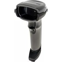
- Symbol MiniScan MSXX07 Series Integration Guide
- Patents
- Warranty
- Revision History
- Table of Contents
- About This Guide
- Chapter 1: Getting Started
- Chapter 2: Installation
- Chapter 3: Scanning
- Chapter 4: Symbol MS1207FZY Specifications
- Chapter 5: Symbol MS1207WA Specifications
- Chapter 6: Symbol MS2207 Specifications
- Chapter 7: Symbol MS2207VHD Specifications
- Chapter 8: Symbol MS3207 Specifications
- Chapter 9: Maintenance and Troubleshooting
- Chapter 10: Parameter Menus
- Chapter 11: RS-232 Interface
- Chapter 12: USB Interface
- Chapter 13: Advanced Data Formatting
- Chapter 14: Mounting Template
- Appendix A: ASCII Character Sets
- Index
- Introduction
- Chapter Descriptions
- Notational Conventions
- Related Documents
- Service Information
- Chapter 1 Getting Started
- Symbol MSXX07 Series Features
- Typical Applications
- Block Diagram
- Miniscan Block Diagram Descriptions
- Chapter 2 Installation
- Unpacking
- Mounting
- Mounting the Scanner on the Optional Stand
- Assembling the Stand
- Mounting the Stand (optional)
- Screw Mount
- Tape Mount
- Mounting the Scanner on the Optional Mounting Bracket
- Connecting the MiniScan
- Connecting the Symbol MSXX07 via USB
- Location and Positioning
- CAUTION
- Using the MiniScan as an Embedded Scanner
- Calculating the Usable Scan Length Method
- Testing the Usable Scan Length Method
- Conveyor Applications
- Symbol is Perpendicular to Conveyor Movement
- Example
- Symbol is Parallel to Conveyor Movement
- Embedded Applications Requiring a Window
- Window Material
- Acrylic
- CR-39
- Chemically Tempered Float Glass
- Window Coatings
- Anti-Reflection Coatings
- Polysiloxane Coating
- Embedded Window Angle and Position
- Accessories
- Application Notes
- TTL RS-232
- USB Warning - Potential Host Side Issues
- Chapter 3 Scanning
- MiniScan Scan Patterns
- Symbol MS1207FZY and MS1207WA Scan Pattern
- Symbol MS2207 and MS2207VHD Scan Patterns
- Smart Raster Scan Pattern
- High Density Single Scan Line Scan Pattern
- Symbol MS3207 Scan Patterns
- Semi-omnidirectional Scan Pattern
- Omnidirectional Scan Pattern
- Scan Angle Selection
- Operation in Blink Mode
- Scanning Tips
- Scan the Entire Symbol
- Position at an Angle
- Trigger Options
- Continuous (Default)
- Level Trigger
- Pulse Trigger
- Blink
- Beeper and LED Definitions
- - 8 Symbol MiniScan MSXX07 Series Integration Guide
- Chapter 4 Symbol MS1207FZY Specifications
- Symbol MS1207FZY Electrical Interface
- Symbol MS1207FZY Mechanical Drawings
- Symbol MS1207FZY Technical Specifications
- Symbol MS1207FZY Decode Zone
- Usable Scan Length
- Chapter 5 Symbol MS1207WA Specifications
- Symbol MS1207WA Electrical Interface
- Symbol MS1207WA Mechanical Drawings
- Symbol MS1207WA Technical Specifications
- Symbol MS1207WA Decode Zone
- Chapter 6 Symbol MS2207 Specifications
- Symbol MS2207 Electrical Interface
- Symbol MS2207 Mechanical Drawings
- Symbol MS2207 Technical Specifications
- Symbol MS2207 Decode Zones
- Symbol MS2207 1D Decode Zone
- Symbol MS2207 1D Decode Distances
- Notes:
- Symbol MS2207 2D Decode Zone
- Symbol MS2207 2D Decode Distances
- Chapter 7 Symbol MS2207VHD Specifications
- Symbol MS2207VHD Electrical Interface
- Symbol MS2207VHD Mechanical Drawings
- Symbol MS2207VHD Technical Specifications
- Symbol MS2207VHD Decode Zones
- Symbol MS2207VHD 1D Decode Zone
- Symbol MS2207VHD 1D Decode Distances
- Symbol MS2207VHD 2D Decode Zone
- Symbol MS2207VHD 2D Decode Distances
- Chapter 8 Symbol MS3207 Specifications
- Symbol MS3207 Electrical Interface
- Symbol MS3207 Mechanical Drawings
- Symbol MS3207 Technical Specifications
- Symbol MS3207 Decode Zones
- Symbol MS3207 Omnidirectional Decode Distances
- Symbol MS3207 2D Slab/Raster Decode Distances
- Chapter 9 Maintenance and Troubleshooting
- Maintenance
- Troubleshooting
- Chapter 10 Parameter Menus
- Operational Parameters
- Default Table
- Set Default Parameter
- Scanning Options
- Beeper Volume
- Beeper Tone
- Beeper Frequency Adjustment
- Laser On Time
- Scan Angle
- Power Mode
- Trigger Mode
- Scanning Mode
- Aiming Mode
- Programmable Raster Height and Raster Expansion Speed
- Timeout Between Decodes
- Timeout Between Decodes, Same Symbol
- Timeout Between Decodes, Different Symbol
- Beep After Good Decode
- Transmit "No Read" Message
- Parameter Scanning
- Linear Code Type Security Level
- Linear Security Level 1
- Linear Security Level 2
- Linear Security Level 3
- Linear Security Level 4
- Bi-directional Redundancy
- UPC/EAN
- Enable/Disable UPC-A
- Enable/Disable UPC-E
- Enable/Disable EAN-13
- Enable/Disable Bookland EAN
- UPC/EAN Coupon Code
- Decode UPC/EAN Supplementals
- Decode UPC/EAN Supplementals (continued)
- User-Programmable Supplementals
- Decode UPC/EAN Supplemental Redundancy
- Transmit UPC-A Check Digit
- Transmit UPC-E Check Digit
- Transmit UPC-E1 Check Digit
- UPC-A Preamble
- UPC-E Preamble
- UPC-E1 Preamble
- Convert UPC-E to UPC-A
- Convert UPC-E1 to UPC-A
- EAN Zero Extend
- Bookland ISBN Format
- UPC/EAN Security Level
- UPC/EAN Security Level 0
- UPC/EAN Security Level 1
- UPC/EAN Security Level 2
- UPC/EAN Security Level 3
- Linear UPC/EAN Decode
- UPC Half Block Stitching
- Code 128
- Enable/Disable Code 128
- Enable/Disable UCC/EAN-128
- Enable/Disable ISBT 128
- Lengths for Code 128
- Code 128 Decode Performance
- Code 128 Decode Performance Level
- Code 39
- Enable/Disable Code 39
- Enable/Disable Trioptic Code 39
- Convert Code 39 to Code 32
- Code 32 Prefix
- Set Lengths for Code 39
- Code 39 Check Digit Verification
- Transmit Code 39 Check Digit
- Code 39 Decode Performance
- Code 39 Decode Performance Level
- Code 93
- Set Lengths for Code 93
- Code 11
- Enable/Disable Code 11
- Set Lengths for Code 11
- Code 11 Check Digit Verification
- Transmit Code 11 Check Digit
- Enable/Disable Interleaved 2 of 5
- Set Lengths for Interleaved 2 of 5
- I 2 of 5 Check Digit Verification
- Transmit I 2 of 5 Check Digit
- Convert I 2 of 5 to EAN-13
- Discrete 2 of 5
- Enable/Disable Discrete 2 of 5
- Set Lengths for Discrete 2 of 5
- Codabar
- Enable/Disable Codabar
- Set Lengths for Codabar
- CLSI Editing
- NOTIS Editing
- MSI Plessey
- Enable/Disable MSI Plessey
- Set Lengths for MSI Plessey
- MSI Plessey Check Digits
- Transmit MSI Plessey Check Digit
- MSI Plessey Check Digit Algorithm
- PDF417/MicroPDF417
- Enable/Disable PDF417
- Enable/Disable MicroPDF417
- MicroPDF Performance
- Code 128 Emulation
- GS1 DataBar
- GS1 DataBar-14
- GS1 DataBar Limited
- GS1 DataBar Expanded
- Convert GS1 DataBar to UPC/EAN
- Composite
- Composite CC-C
- Composite CC-A/B
- Composite TLC-39
- UPC Composite Mode
- Data Options
- Transmit Code ID Character
- Transmit Code ID Character (continued)
- Prefix/Suffix Values
- Scan Data Transmission Format
- Event Reporting
- Decode Event
- Boot Up Event
- Parameter Event
- Macro PDF Features
- Transmit Symbols in Codeword Format
- Transmit Unknown Codewords
- Escape Characters
- Delete Character Set ECIs
- ECI Decoder
- Transmit Macro PDF User-Selected Fields
- Transmit File Name
- Parameter # B0h
- Transmit Block Count
- Transmit Time Stamp
- Transmit Sender
- Transmit Checksum
- Transmit File Size
- Transmit Macro PDF Control Header
- Last Blocker Marker
- Numeric Bar Codes
- Cancel
- Chapter 11 RS-232 Interface
- RS-232 Default Parameters
- RS-232 Host Parameters
- RS-232 Host Parameters (continued)
- RS-232 Host Types
- Baud Rate
- Parity
- Stop Bit Select
- Data Bits
- Check Receive Errors
- Hardware Handshaking
- None
- Standard RTS/CTS
- RTS/CTS Option 1
- RTS/CTS Option 2
- RTS/CTS Option 3
- Software Handshaking
- ACK/NAK
- ENQ
- ACK/NAK with ENQ
- XON/XOFF
- Host Serial Response Time-out
- RTS Line State
- Beep on
- Intercharacter Delay
- Nixdorf Beep/LED Options
- Ignore Unknown Characters
- Chapter 12 USB Interface
- Connecting a USB Interface
- USB Default Parameters
- USB Host Parameters
- USB Device Type
- USB Country Keyboard Types (Country Codes)
- USB Keystroke Delay
- USB CAPS Lock Override
- USB Ignore Unknown Characters
- Emulate Keypad
- USB Keyboard FN 1 Substitution
- Simulated Caps Lock
- Convert Case
- Chapter 13 Advanced Data Formatting
- Rules: Criteria Linked to Actions
- Using ADF Bar Codes
- ADF Bar Code Menu Example
- Rule 1: The Code 128 Scanning Rule
- Step Bar Code On Page Beep Indication
- Rule 2: The UPC Scanning Rule
- Alternate Rule Sets
- Rules Hierarchy (in Bar Codes)
- Default Rules
- ADF Bar Codes
- Special Commands
- Pause Duration
- Begin New Rule
- Save Rule
- Erase
- Quit Entering Rules
- Disable Rule Set
- Criteria
- Code Types
- Code Types (continued)
- Code Lengths
- Code Lengths (continued)
- Message Containing A Specific Data String
- Specific String at Start
- Specific String, Any Location
- Any Message OK
- Numeric Keypad
- Rule Belongs To Set
- Actions
- Send Data
- Send Data (continued)
- Setup Field(s)
- Move Cursor
- Send Pause
- Skip Ahead
- Skip Back
- Send Preset Value
- Modify Data
- Remove All Spaces
- Crunch All Spaces
- Stop Space Removal
- Remove Leading Zeros
- Stop Zero Removal
- Pad Data with Spaces
- Pad Data with Zeros
- Pad Data with Zeros (continued)
- Beeps
- Send Keystroke (Control Characters and Keyboard Characters)
- Keyboard Characters
- Send Keypad Characters (continued)
- Send Right Control Key
- Send Graphic User Interface (GUI) Characters
- Turn On/Off Rule Sets
- Turn On/Off Rule Sets (continued)
- Alphanumeric Keyboard (continued)
- Chapter 14 Mounting Template
- Symbol MS1207FZY/MS1207WA/MS2207/MS2207VHD Mounting Template
- Symbol MS3207 Mounting Template
- Appendix A ASCII Character Sets
- RS-232 ASCII Character Set
- USB ASCII Character Set
- Glossary
- A
- B
- bps. See Bits Per Second.
- C
- D
- E
- F
- G
- H
- |
- K
- L
- M
- N
- O
- P
- Q
- R
- s
- T
- U
- V
- W
- X
- Y
- installation
- mechanical drawing
- laser class
- laser power
- LED
- macro PDF
- 0
- parameters
- power requirements
- print contrast
- programming bar codes
- Tell Us What You Think...
- MOTOROLA
Brand : MOTOROLA
Model : MS1207WA
Category : Barcode Reader