SA-24600HD - Voice recorder Provision-ISR - Free user manual and instructions
Find the device manual for free SA-24600HD Provision-ISR in PDF.

| Product Type | Voice Recorder |
| Brand | Provision-ISR |
| Model | SA-24600HD |
| Dimensions | 120 x 70 x 20 mm |
| Weight | 150 g |
| Power Source | DC 5V / USB |
| Recording Formats | MP3, WAV |
| Storage | Internal 8 GB memory, expandable via MicroSD card up to 32 GB |
| Battery | Rechargeable lithium-ion, 2000 mAh |
| Recording Time | Up to 24 hours (depending on settings) |
| Display | LCD screen with backlight |
| Microphone | Built-in stereo microphone |
| Speaker | Built-in speaker |
| Connectivity | USB 2.0, 3.5 mm headphone jack |
| Main Functions | Voice activation, noise reduction, loop recording, password protection, timestamp |
| Maintenance | Clean with a soft, dry cloth. Keep away from liquids. |
| Safety | Do not expose to water or extreme temperatures. Do not disassemble. |
| Spare Parts | Not user-replaceable; contact support for service |
| Repairability | Non-user-serviceable. Contact authorized service center. |
| General Information | User manual available online at notice-facile.com |
Frequently Asked Questions - SA-24600HD Provision-ISR
User questions about SA-24600HD Provision-ISR
0 question about this device. Answer the ones you know or ask your own.
Ask a new question about this device
Download the instructions for your Voice recorder in PDF format for free! Find your manual SA-24600HD - Provision-ISR and take your electronic device back in hand. On this page are published all the documents necessary for the use of your device. SA-24600HD by Provision-ISR.
USER MANUAL SA-24600HD Provision-ISR
natural_image
Three black PROVISION 15R audio equipment units with control knobs and buttons (no visible text or symbols on the devices themselves)Digital Video Recorder User Manual
CAUTION
- Read this user manual carefully to ensure correct and safe use of your PROVISION-ISR DVR.
- The content of this manual could be outdated or incorrect, for any clarification contact PROVISION-ISR support.
- This device should be operated only from the type of power source indicated on the marking label. The voltage of the power must be verified before using.
- If you plan not to use the DVR for a long time, shutdown and unplug the power cable.
- Do not place this device close to a heat sources (e.g. radiators, heat registers, stoves or other device).
- Do not place this device near water. Clean only with a dry cloth
- Do not block any ventilation openings and make surethe device is in a ventilated place.
- Avoid damaging the HDD, neverunpluga DVR!! If the DVR is working, the recording must be ended before shutting it down.
Press the "shut down" button from the main menu, and wait for this message: "Now you can unplug the DVR". - This equipment is for indoor use only.
- Do not expose the DVR to rain, to high humidity, or to extreme temperature conditions.
- In case any solid or liquid get inside the DVR:shut down and unplug the power line and call a qualified technician.
- Refer all servicing to qualified service personnel. No any parts repaired by yourself without technical aid or approval.
- This manual is suitable for the PROVISION-ISR 4/8/16/32 channel digital video recorders.
- All examples and pictures used in this manual are from PROVISION-ISR DVRs.
Digital Video Recorder User Manual
Table of Contents
1 Introduction....1
1.1 DVR Introduction .... 1
2 Hardware Installation....4
2.1 Install Hard Drive &DVD Writer....4
2.1.1 Install the Hard Drive (1U and small 1U DVR case)....4
2.1.2 Install the DVD Writer (1U DVR case)....5
2.1.3 Install the DVD Writer (2U DVR case)....5
2.1.4 Install the Hard Drive (2U DVR case) 6
2.1.5 Install the DVD Writer (2U DVR case)....8
2.2Front Panel Descriptions: 9
2.2.1 Front Panel Description (1U DVR case): 9
2.2.2Front Panel Description (small 1U DVR case):....10
2.2.3 Front Panel Description (2U DVR case)....11
2.3 Rear Panel Descriptions....13
2.3.1 Rear Panel Description (SA-4100HDX+)....13
2.3.2 Rear Panel Description (SA-4100HDE+). 14
2.3.3 Rear Panel Description (SA-8200N+). 15
2.3.4 Rear Panel Description (SA-16400N+). 16
2.3.5 Rear Panel Description (SA-16400NE+) 17
2.3.6 Rear Panel Description (SA-8200HD+)....18
2.3.7 Rear Panel Description (SA-8100SDI)....19
2.3.8Rear Panel Description (SA-4025SDI)....20
2.3.9 Rear Panel Description (SA-4100SDI)....21
2.3.10 Rear Panel Description (SA-24600)....22
2.3.11Rear Panel Description (SA-32800)....23
2.3.12 Rear Panel Description (SA-8200D1SDI)....24
Digital Video Recorder User Manual
2.3.13 Rear Panel Description (SA-8200SDI)....25
2.3.14 Rear Panel Description (SA-16200SDI/SA-16400SDI)....26
2.4 Remote Controller....27
2.5 Control with Mouse 30
2.5.1 Connect Mouse....30
2.5.2 Use Mouse....30
3 Basic Function Instruction 31
3.1 Power On/Off 31
3.1.1 Power on 31
3.1.2 Power off....31
3.2 Login....32
3.3 Live preview ....32
3.3.1 Live playback....33
4 Main menu setup guide....34
4.1 Basic configuration 35
4.1.1 System....35
4.1.2 Time & date....36
4.1.3 DST....37
4.2 Live configuration....37
4.2.1 Live 37
4.2.2 Main monitor....38
4.2.3 Spot 39
4.2.4 Mask....39
4.3 Record configuration....40
4.3.1 Enable 40
4.3.2 Record stream....41
4.3.3 Time 41
Digital Video Recorder User Manual
4.3.4 Stamp 42
4.3.5 Recycle record....43
4.3.6 Snap....43
4.4 Schedule configuration....43
4.4.1 Schedule....43
4.4.2Motion....45
4.4.3 Sensor....45
4.5 Alarm configuration 46
4.5.1 Sensor....46
4.5.2 Motion....48
4.5.3 Video loss....50
4.5.4Other alarm 51
4.5.5 Alarm out....52
4.6 Network configuration....53
4.6.1 Network....53
4.6.2 Sub stream....54
4.6.3Email 55
4.6.4 Other settings ....55
4.7P.T.Z configuration....60
4.8 Advanced....63
4.8.1 Reset....64
4.8.2 Import/Export....64
4.8.3 Block/Allow list....64
5 Record search & playback and backup 65
5.1 Time search....65
5.2 Event search....66
5.3 File management....67
Digital Video Recorder User Manual
5.4 Image 68
5.5 Backup....68
6 Manage DVR....69
6.1 Check system information....69
6.1.1 System information....69
6.1.2 Event information....69
6.1.3 Log information 69
6.1.4 Network information....69
6.1.5 Online information....69
6.1.6 Recording data 69
6.2 Manual alarm 70
6.3 Disk management....70
6.4 Upgrade....70
6.5 Logoff 70
7 Remote Surveillance....71
7.1 IE Remote Surveillance....71
7.1.1 On LAN....71
7.1.2 On WAN....71
7.2 Remote Surveillance through Macintosh with Safari: 73
7.2.1 On LAN....74
7.2.2 On WAN....76
7.3 The remote live preview interface....77
7.4 Remote playback & backup 80
7.4.1 Remote playback....80
7.4.2 Remote backup....86
7.5 Remote System configuration....87
7.6 Remote Management 88
Digital Video Recorder User Manual
Remote Information Search 88
8 Mobile Surveillance 89
8.1 iPhone/iPad app (SuperLivePro for iOS): 89
8.2 SuperLivePro 1.0 Manual (for iOS)....90
8.4 Windows Mobile application 96
8.5 Symbian OS application....97
8.6 BlackBerry OS application installation guide 99
8.6.1 Installation instruction for BlackBerry Mobile phone Client 99
8.6.2 BlackBerry OS application guide....101
Appendix A Q&A 105
Appendix B Calculate Recording Capacity....111
Appendix C Compatible Devices....112
Appendix D 4CH DVR Specifications....114
Appendix E 8CH DVR Specifications....115
Appendix G 24CH/32CH DVR Specifications....117
Digital Video Recorder User Manual
1 Introduction
1.1 DVR Introduction
Thesemodel DVRs (Digital Video Recorder) are designed specifically for CCTV system. The device contains high-performance video processing chips and an embedded Linux system, it utilizes advanced standard technologies, such as H.264 with low bit rate, Dual stream, SATA interface, VGA output mouse supported, IE browser supported with full remote control, mobile view(by phones) and more. All those ensure its superior and stable performance. Due to these distinctive characteristics, it is widely used in banks, telecommunication, transportation, factories, warehouse, irrigation and more.
This manual is for the following DVRs:thesmall1U case DVR: SA-16400N+, SA-8200N+, SA-4100HDE+, SA-4100HDX+, the 1U case DVRs: SA-16400NE+, SA-16400HD+, SA-8200HD+, SA-8100SDI, SA-4025SDI, SA-4100SDI, SA-24600, and the 2U case DVRs: SA-32800, SA-8200D1SDI, SA-8200SDI, SA-16200SDI, SA-16400SDI
Main Features
COMPRESSION FORMAT
• Standard H.264 compression with low bit rate and better image quality.
• Supports mixed D1 and CIF resolutions.
• SA-32800 supports D1 on four channels: 1,9,17 and 25 (25 fps).
LIVE SURVEILLANCE
• Supports VGA output (and zoom X4 option).
• Supports HDMI output (not the SA-24600 DVR model)
• Supports channel security by hiding live display.
• Displays the local record state and basic information.
• Supports USB mouse for full control.
RECORD MEDIA
• 1U case and 2U case DVRsupportsinstallation of additional SATA hard drives.
Digital Video Recorder User Manual
• Supports zoomX4 option during playback.
BACKUP
• SupportsUSB 2.0 devices for backup.
• Supports installation of a built-in SATA DVD writer for backup (not small 1U case DVR).
• Supportssaving recorded files with AVI standard format for a remote computer through internet.
• Supports import/export of definitions/settings.
• Supports E-mail Notification function with (or without) attached snapshot.
RECORD & PLAYBACK
- Record modes: Manual, Schedule, Motion detection and Sensor alarm recording.
• Supports recycle recording after HDD is full.
• Resolution, frame rate and picture quality are adjustable.
• 128MB for every video file packaging.
• Up to 16audio channels.
• Record search mode: time search and event search.
• Supports playback of all camerassimultaneously.
• Supports deleting orprotectingspecified recorded files.
• Supports remote playback in NetworkClientthrough LAN or internet.
ALARM
• 1 or 4 alarm output channels(4 channels in 2U case DVR) and 4, 8, or 16 alarm inputchannels.
• Supports schedule for motion detection and sensor alarm.
• Supports pre-recording and post recording.
• Motion or alarm triggers recording/PTZ predefined control/e-mail notification/buzzer of predefined channels.
• Supports linked PTZ preset, auto cruise and track of the corresponding channel.
Digital Video Recorder User Manual
PTZ CONTROL
• Supports multiple PTZ protocols.
• Supports128 PTZ presets and 8 auto cruise tracks.
• Supportsremote PTZ control through internet.
SECURITY
- Usermanagement: log search, system setup, two way audio, file management, disk management, remote login, live view, manual record, playback, PTZ control and remote live view.
• Supports1 administrator and 63 usernames and linked passwords w/wo associated Mac address.
• Supports event log recording and viewing, unlimited number of events.
• Supports disconnecting online users.
• Supports two-way audio function.
NETWORK
• Supports TCP/IP, DHCP, PPPoE, DDNS protocols.
• Supports IE browser for remote view.
• Supports limiting the maximum number of online clients (5 users for 4/8 channel DVR and 10 users for 16/32 channel DVR).
● Supports dual stream. Network stream is adjustable independently to fit the network bandwidth and environment.
• Supportssnap picture.
• Supports color adjustment in remote live
• Supports remote timesearch, event search, and channel playback with picture snap.
• Supports remote PTZ control with preset and auto cruise.
• Supports remote full menu setup, changing all the DVR parameters remotely.
• Supports mobile surveillance by smart phones; iPhone, Android, Symbian, WinCE and blackberry.
• SupportsCMS; designated program for remote management of multiple devices
- For NE/HD series DVR supports IP block/allow list via the internet.
Digital Video Recorder User Manual
2 Hardware Installation
Notice: Check the unit and the accessories after getting the DVR.
shut down the device and unplug the power line before any new connections to other devices. Don't hot plug in/out
Please note:
Small1U case DVR: SA-16400N+, SA-8200N+, SA-4100HDE+, SA-4100HDX+
1U case DVR: SA-16400NE+, SA-16400HD+, SA-8200HD+, SA-8200SDI, SA-4025SDI, SA-4100SDI, SA-24600
2U case DVR:SA-32800, SA8200D1SDI, SA-8200SDI, SA-16200SDI, SA-16400SDI
2.1 Install Hard Drive & DVD Writer
2.1.1 Install the Hard Drive(1U and small 1U DVR case)
Notice: 1. The 1U and 2U DVR units support multiple SATA hard drives (the small 1U case DVR supports one hard drive). Please use the hard drive on the compatible devices listespecially for security and safe field.
- Please calculate HDD capacity according to the recording setting. Please refer to "Appendix B Calculate Recording Capacity".
Step1: unplug the DVR from the power line, then unscrew and carefully open the top cover
Step2:Connect the HDD power and data cables. Place the HDD on the bottom case as Fig2.1.
Step3:Secure the HDD using the appropriate screws(Fig2.2)
Note: For easeof installment: connect the cables beforefastening the HDD to the bottom plate.
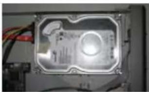
natural_image
Interior view of an electronic device casing with visible circuitry and wiring (no text or symbols)Fig 2.1 HDD placement
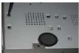
natural_image
Close-up of a computer monitor with ventilation grille and control buttons (no visible text or symbols)Fig 2.2 Securing the HDD
Digital Video Recorder User Manual
2.1.2 Install the DVD Writer (1U DVR case)
Notice: 1. The DVD writers must be on the compatible devices list.
Please refer to "Appendix C Compatible Devices"
- This device is only for backup
Step1:unplug from the power line, then unscrew and carefully open the top cover
Step2: Connect the power and data cables, and then place the DVD writer on the bottom case as Fig2.3.
Step3: Secure the DVD writer using the appropriate screws (Fig2.4)
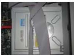
natural_image
Interior view of a computer room with monitor, keyboard, and mouse (no visible text or symbols)Fig 2.3 DVD Writer placement
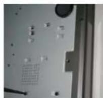
natural_image
Close-up of a mechanical component with holes and a grid pattern (no visible text or symbols)Fig 2.4 fasten the Writer
2.1.3 Install the DVD Writer(2U DVR case)
Notice: 1. The writers must be on the compatible devices list. Please refer to "Appendix C Compatible Devices" 2. This device is only for backup
Step1:unplug the DVR from the power line, unscrew and Open the top cover
Step2: Connect the HDD power / data cables. Place the DVD writer onto the bottom case as below.
Step3: Secure the DVD writer using the appropriate screws.
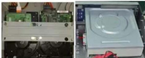
natural_image
Two views of an electronic device showing a circuit board and a circular display unit (no visible text or symbols)Fig 2.1 Connect HDDFig 2.2 Connect the DVD Writer (Besides the HDD)
Digital Video Recorder User Manual
2.1.4 Install the Hard Drive(2U DVR case)
Notice: 1. This series support four SATA hard drives or three SATA hard drives plus one DVD writer. (User can also choose to install eight SATA hard drives or four SATA hard drives plus one DVD writer. Here take eight SATA hard drives installation for example). Use the hard drive onthe compatible devices list. Please refer to "Appendix C Compatible devices".
2. Please calculate HDD capacity according to the recording setting. Please refer to "Appendix B Calculate Recording Capacity".
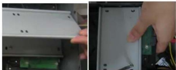
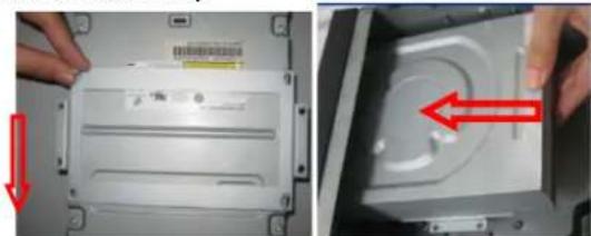
Step 1: Unscrew and open the case and then unscrew the screws in the both sides to take out of the upper iron bar as shown below:
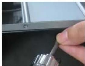
natural_image
Close-up of a hand holding a metallic tool, partially visible against a dark background (no text or symbols)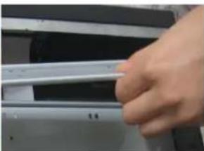
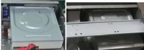
natural_image
Close-up of a hand holding a white object over a dark surface, possibly a laptop or electronic device (no visible text or symbols)Step 2: Place the HDD under the lower iron bar and aim the screw holes of the HDD at the iron bar holes. Then screw firmly and connect the power and data cables. The pictures are shown as follows:
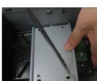
natural_image
Close-up of a hand holding a screwdriver inserted into a device component (no visible text or symbols)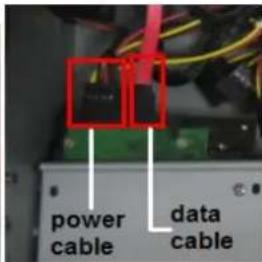
Digital Video Recorder User Manual
Step 3: Install other three HDD according to above-mentioned method. Then cover the upper iron bar and screw it firmly. Place the HDD under the iron bar and secure as shown below:
natural_image
Close-up of a hand inserting a white plastic component into a device (no visible text or symbols)Step 4: Install up to four HDDs under the upper iron bar as shown below:
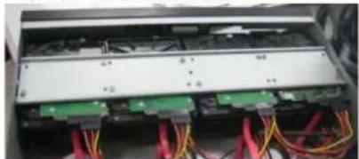
natural_image
Interior view of an electronic device showing a circuit board with multiple connected components and red cables (no visible text or symbols)Digital Video Recorder User Manual
2.1.5 Install the DVD Writer(2U DVR case)
Step 1: Unscrew and open the case. Then unscrew the screws on both sides to remove the upper bar as shown below:
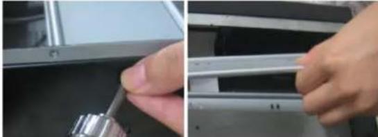
natural_image
Close-up of hands installing or adjusting a metal component on a mechanical assembly (no visible text or symbols)Step 2: Install the DVD holder that came with the device. Please let the screw holes of the DVD aim and the bolts. Try to place the holder farther away from the front and then screw firmly. Then, put the DVD with the holder into the case and let the screw holes of the case aim at the holder's. Next, tighten the bolts firmly.
natural_image
Two-panel image showing a computer drive with a red arrow indicating the next close-up (no text or symbols visible)Step 3: Connect the power and data cables and install the upper iron bar. Then, screw firmly with screws in the both sides.
natural_image
Two views of a white electronic device casing, one open and one closed, showing internal components (no visible text or symbols)Note: The DVD installation uses a space that could be used to install a hard drive.
Digital Video Recorder User Manual
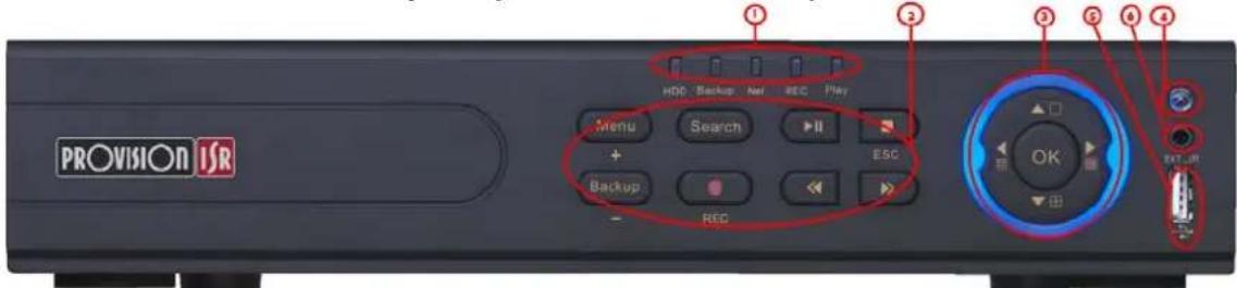
2.2 Front Panel Descriptions:
2.2.1 Front Panel Description (1U DVR case):

| Item | Type | Name Description | |
| 1 | Work state indicator | Power | Power indicator, when connection , the light is blue |
| HDD | When HDD is writing and reading , the light is blue | ||
| Net | When access to network , the light is blue | ||
| Backup | When backup files and data, the light is blue | ||
| Play | When playing video, the light is blue | ||
| REC | When recording, the light is blue | ||
| 2 | Compound button | MENU/+ | 1. Enter menu in live 2. Increase the value in setup |
| BACKUP/- | 1. Decrease the value in setup2. Enter backup mode in live | ||
| RECORD/FOCUS | 1. Record manually2. FOCUS function enables at PTZ mode. | ||
| REW/SPEED | 1. Rewind key2. SPEED function enables at PTZ mode | ||
| SEARCH/ZOOM | 1. Enter search mode2.ZOOM function enables at PTZ mode. | ||
| PLAY /IRIS | 1. Enter play interface2. IRIS function enables at PTZ mode | ||
| FF/ P.T.Z. | 1. Fast forward2. Enter PTZ mode in live | ||
| STOP/ESC | 1. Quit play mode2. Exit the current interface or status | ||
| 3 | Digital button | 1-9 or 0/10+ | Input number 1-9 or choose camera / Input number0, 10 and the above number together with other digital keys |
| 4 | Input button | Direction button Change direction to select items | |
| Multi-screen | Change screen display mode like1/4/9/16 channel | ||
| Enter button Confirm selection | |||
| 5 | IR receiver | IR | Remote controller receiver |
| 6 | USB | USB port | external USB devices for USB flash, USB HDD for backup, firmware update or connect to USB mouse |
| 7 | Extension | EXT_IR | To connect to external cable for IR receiver |
Digital Video Recorder User Manual
2.2.2 Front Panel Description(small 1U DVR case):
| Item | Type | Name Description | |
| 1 | Work state indicator | Power | Power indicator, when connection , the light is blue |
| HDD | When HDD is writing and reading , the light is blue | ||
| Net | When access to network , the light is blue | ||
| Backup | When backup files and data, the light is blue | ||
| Play | When playing video, the light is blue | ||
| REC | When recording, the light is blue | ||
| 2 | Compound button | MENU/+ | 1. Enter menu in live 2. Increase the value in setup |
| BACKUP/- | 1. Decrease the value in setup2. Enter backup mode in live | ||
| RECORD/FOCUS | 1. Record manually2. FOCUS function enables at PTZ mode. | ||
| REW/SPEED | 1. Rewind key 2. SPEED function enables at PTZ mode | ||
| SEARCH/ZOOM | 1. Enter search mode2.ZOOM function enables at PTZ mode. | ||
| PLAY /IRIS | 1. Enter play interface2. IRIS function enables at PTZ mode | ||
| FF/ P.T.Z. | 1. Fast forward2. Enter PTZ mode in live | ||
| STOP/ESC | 1. Quit play mode2. Exit the current interface or status | ||
| 3 | Input button | Direction button | Change direction to select items |
| Multi-screen | Change screen display mode like1/4/9 channel | ||
| Enter button | Confirm selection | ||
| 4 | IR receiver | IR | Remote controller receiver |
| 5 | USB | USB port | external USB devices (USB flash, USB HDD for backup, update firmware, USB mouse) |
| 6 | External IR | EXT_IR | Extension for the IR receiver |
Digital Video Recorder User Manual
2.2.3 Front Panel Description (2U DVR case)
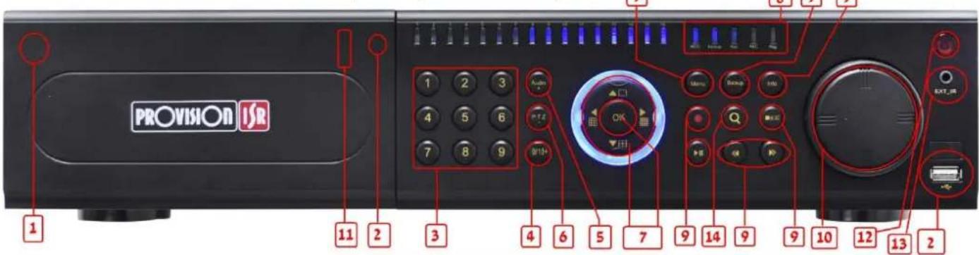
| Item | Name | Function | |
| 1 | Power Button | Soft switch off to stop firmware running. Do it before power off. | |
| 2 | DVD button | Press this button, user can place the DVD to do backup. | |
| 3 | Keys 0-9 | Input number 1-9 or choose camera | |
| 4 | (0/——) | 1. represents decade number. 2. Indicates digital number 0 | |
| 5 | AUDIO/+ | 1. Control voice2. Increase the value in setup | |
| 6 | P.T.Z./ - | 1. Enter PTZ mode in live2. Decrease the value in setup | |
| 7 | Input button | Direction button | Change direction to select items |
| Multi-screen | Change screen display mode like1/4/9/16 channel | ||
| Enter button | Confirm selection | ||
| 8 | Work state indicator | REC | When recording, the light is blue |
| HDD | When HDD is writing and reading , the light is blue | ||
| Backup | When backup files and data, the light is blue | ||
| Net | When access to network , the light is blue | ||
| Play | When playing video, the light is blue | ||
| Power | Power indicator, when connection , the light is blue | ||
| 9 | Function button | MENU | Enter menu in live |
| INFO | Check data, same as: Main menu=>Information | ||
Digital Video Recorder User Manual
| Item | Name | Function | |
| BACKUP | Enter backup mode in live | ||
| SEARCH | Enter search mode | ||
| REW | Rewind | ||
| FF | Fast forward | ||
| REC | Record manually | ||
| PLAY | Play/Pause | ||
| STOP | Stop/Esc | ||
| 10 | Jog dial | Control rewind/fast forward/frame when playing the image. | |
| 11 | USB port | external USB devices (USB flash, USB HDD for backup, update firmware, USB mouse) | |
| 12 | IR receiver | IR | Remote controller receiver |
| 13 | External IR | EXT_IR | Extension for the IR receiver |
Digital Video Recorder User Manual
2.3 RearPanel Descriptions
2.3.1 Rear Panel Description(SA-4100HDX+)
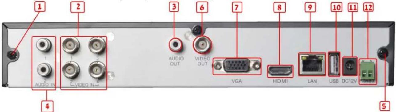
| Item | Name | Description |
| 1 | Ground connection | Grounding (also for the alarm in ground connection) |
| 2 | Video in | Video input channels from 1-4 |
| 3 | Audio out | Auxiliary audio output |
| 4 | Audio in | 2 CH Audio input |
| 5 | Ground connection | Connect to ground (choose only one ground, do not connect both!) |
| 6 | Video out | Video output (BNC) |
| 7 | VGA port | VGA output, connect to monitor |
| 8 | HDMI | HDMI output, connect to monitor |
| 9 | LAN | Network port |
| 10 | USB port | Connect USB mouse or connect external USB devices |
| 11 | DC12V | POWER INPUT |
| 12 | RS485 | Connect to speed dome (RS485 PTZ cameras) |
Digital Video Recorder User Manual
2.3.2 Rear Panel Description (SA-4100HDE+)

| Item | Name | Description |
| 1 | Audio in | 4 CH Audio input |
| 2 | Video in | Video input channels from 1-4 |
| 3 | Ground | Grounding (also for the alarm in ground connection) |
| 4 | Audio out | Auxiliary audio output |
| 5 | Video out | Connect to monitor |
| 6 | Spot | Connect to monitor with no menu display |
| 7 | Power switch | ON/OFF switch |
| 8 | RS485 | Connect to speed dome (RS485 PTZ cameras) |
| 9 | ALARM OUT | 1-ch relay output. Connect to external alarm |
| 10 | ALARM IN | Connect to external sensor1-4 |
| 11 | HDMI | HDMI output, connect to monitor |
| 12 | VGA port | VGA output, connect to monitor |
| 13 | LAN | Network port |
| 14 | USB | Connect the USB mouse or an external USB device |
| 15 | DC12V | POWER INPUT |
Digital Video Recorder User Manual
2.3.3 Rear Panel Description (SA-8200N+)
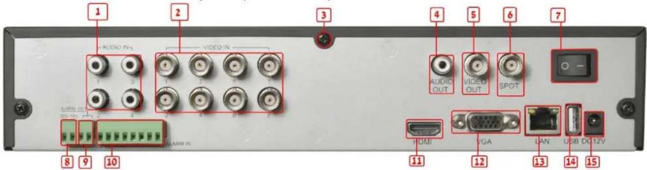
| Item | Name Description | |
| 1 | Audio in | 4 CH Audio input |
| 2 | Video in | Video input channels from 1-8 |
| 3 | Ground | Grounding (also for the alarm in ground connection) |
| 4 | Audio out | Auxiliary audio output |
| 5 | Video out | Connect to monitor |
| 6 | Spot | Connect to monitor with no menu display |
| 7 | Power switch | ON/OFF switch |
| 8 | RS485 | Connect to speed dome (RS485 PTZ cameras) |
| 9 | ALARM OUT | 1-ch relay output. Connect to external alarm |
| 10 | ALARM IN | Connect to external sensor 1-8 |
| 11 | HDMI | HDMI output, connect to monitor |
| 12 | VGA port | VGA output, connect to monitor |
| 13 | LAN | Network port |
| 14 | USB | Connect the USB mouse or an external USB device |
| 15 | DC12V | POWER INPUT |
Digital Video Recorder User Manual
2.3.4 Rear Panel Description (SA-16400N+)
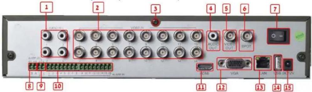
| Item | Name Description | |
| 1 | Audio in | 4 CH Audio input |
| 2 | Video in | Video input channels from 1-16 |
| 3 | Ground | Grounding (also for the alarm inground connection) |
| 4 | Audio out | Auxiliary audio output |
| 5 | Video out | Connect to monitor |
| 6 | Spot | Connect to monitor with no menu display |
| 7 | Power switch | ON/OFF switch |
| 8 | RS485 | Connect to speed dome (RS485 PTZ cameras) |
| 9 | ALARM OUT | 1-ch relay output. Connect to external alarm |
| 10 | ALARM IN | Connect to external sensor 1-16 |
| 11 | HDMI | HDMI output, connect to monitor |
| 12 | VGA port | VGA output, connect to monitor |
| 13 | LAN | Network port |
| 14 | USB | Connect the USB mouse or an external USB device |
| 15 | DC12V | POWER INPUT |
Digital Video Recorder User Manual
2.3.5 Rear Panel Description (SA-16400NE+)
| Item | Name Description | |
| 1 | Power switch | ON/OFF switch |
| 2 | P/Z | Connect to speed dome (RS485 PTZ cameras) |
| 3 | K/B | Connect to keyboard |
| 4 | Audio in | 4 CH Audio input |
| 5 | Video out | Connect to monitor |
| 6 | Video in | Video input channels from 1-16 |
| 7 | VGA port | VGA output, connect to monitor |
| 8 | FAN | Fan for ventilation, DO NOT COVER THE FAN. |
| 9 | DC12V | POWER INPUT |
| 10 | Ground | Grounding (also for the alarm in ground connection) |
| 11 | ALARM IN | Connect to external sensor 1-16 |
| 12 | Audio out | Auxiliary audio output |
| 13 | Spot | Connect to monitor with no menu display |
| 14 | HDMI | HDMI output, connect to monitor |
| 15 | USB | Connect the USB mouse or an external USB device |
| 16 | LAN | Network port |
| 17 | ALARM OUT | 1-ch relay output. Connect to external alarm |
Digital Video Recorder User Manual
2.3.6 Rear Panel Description(SA-8200HD+)
| Item | Name Description | |
| 1 | Power switch | ON/OFF switch |
| 2 | P/Z | Connect to speed dome (RS485 PTZ cameras) |
| 3 | K/B | Connect to keyboard |
| 4 | Audio in | 4 CH Audio input |
| 5 | Audio out | Auxiliary audio output |
| 6 | Spot | Connect to monitor with no menu display |
| 7 | Video out | Connect to monitor |
| 8 | FAN | Fan for ventilation, DO NOT COVER THE FAN. |
| 9 | DC12V | POWER INPUT |
| 10 | Ground | Grounding (also for the alarm in ground connection) |
| 11 | ALARM IN | Connect to external sensor 1-8 |
| 12 | HDMI | HDMI output, connect to monitor |
| 13 | VGA port | VGA output, connect to monitor |
| 14 | USB | Connect the USB mouse or an external USB device |
| 15 | LAN | Network port |
| 16 | Video in | Video input channels from 1-8 |
| 17 | ALARM OUT | 1-ch relay output. Connect to external alarm |
Digital Video Recorder User Manual
2.3.7 Rear Panel Description(SA-8100SDI)
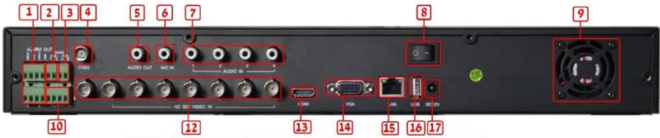
| Item | Name | Description |
| 1 | ALARM OUT | 4-ch relay output. Connect to external alarm |
| 2 | P/Z | Connect to speed dome (RS485 PTZ cameras) |
| 3 | K/B | Connect to keyboard |
| 4 | Video out | Connect to monitor |
| 5 | Audio out | Auxiliary audio output |
| 6 | MIC IN | Auxiliary audio input for personal microphone |
| 7 | Audio in | 4 CH Audio input |
| 8 | Power switch | ON/OFF switch |
| 9 | FAN | Fan for ventilation, DO NOT COVER THE FAN. |
| 10 | ALARM IN | Connect to external sensor 1-4 |
| 12 | Video in | HD SDI Video input channels 1-8 |
| 13 | HDMI | HDMI output, connect to monitor |
| 14 | VGA | VGA output, connect to monitor |
| 15 | LAN | Network port |
| 16 | USB | Connect the USB mouse or an external USB device |
| 17 | DC12V | POWER INPUT |
Digital Video Recorder User Manual
2.3.8 Rear Panel Description(SA-4025SDI)
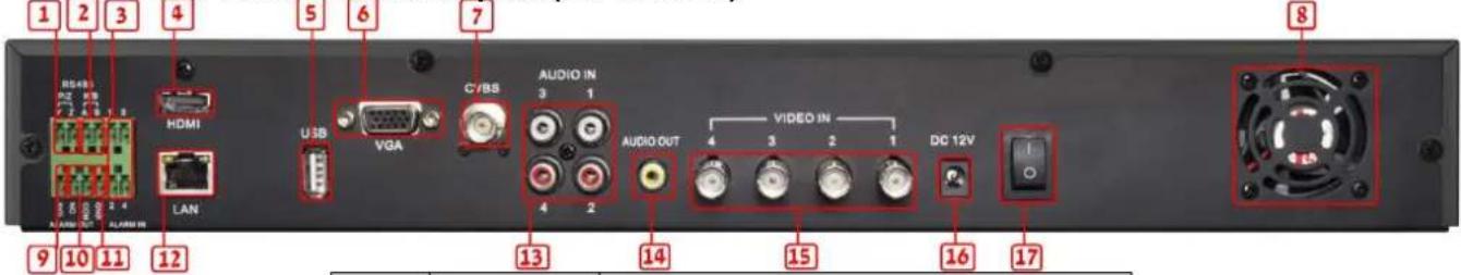
| Item | Name Description | |
| 1 | P/Z | Connect to speed dome (RS485 PTZ cameras) |
| 2 K/B | Connect to keyboard | |
| 3 | ALARM IN | Connect to external sensor 1-4 |
| 4 | HDMI | HDMI output, connect to monitor |
| 5 | USB | Connect the USB mouse or an external USB device |
| 6 | VGA port | VGA output, connect to monitor |
| 7 | Video out | Connect to monitor |
| 8 | FAN | Fan for ventilation, DO NOT COVER THE FAN. |
| 9 | + 5V | +5 Volt |
| 10 | ALARM OUT | 1-ch relay output. Connect to external alarm |
| 11 | Ground | Grounding (also for the alarm in ground connection) |
| 12 | LAN | Network port |
| 13 | Audio in | 4 CH Audio input |
| 14 | Audio out | Auxiliary audio output |
| 15 | Video in | Video input channels from 1-4 |
| 16 | DC12V | POWER INPUT |
| 17 | Power switch | ON/OFF switch |
Digital Video Recorder User Manual
2.3.9 Rear Panel Description(SA-4100SDI)
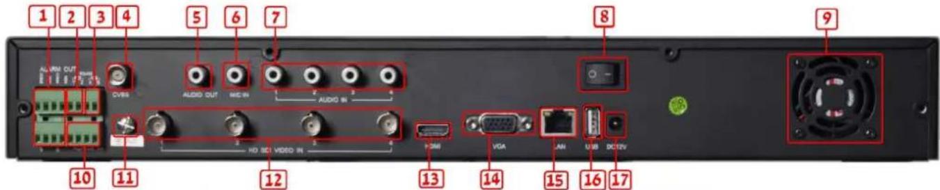
| Item | Name | Description |
| 1 | ALARM OUT | 4-ch relay output. Connect to external alarm |
| 2 | P/Z | Connect to speed dome (RS485 PTZ cameras) |
| 3 | K/B | Connect to keyboard |
| 4 | Video out | Connect to monitor |
| 5 | Audio out | Auxiliary audio output |
| 6 | MIC IN | Auxiliary audio input for personal microphone |
| 7 | Audio in | 4 CH Audio input |
| 8 | Power switch | ON/OFF switch |
| 9 | FAN | Fan for ventilation, DO NOT COVER THE FAN. |
| 10 | ALARM IN | Connect to external sensor 1-4 |
| 11 | Ground | Grounding (also for the alarm in ground connection) |
| 12 | Video in | HD SDI Video input channels 1-4 |
| 13 | HDMI | HDMI output, connect to monitor |
| 14 | VGA | VGA output, connect to monitor |
| 15 | LAN | Network port |
| 16 | USB | Connect the USB mouse or an external USB device |
| 17 | DC12V | POWER INPUT |
Digital Video Recorder User Manual
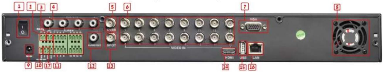
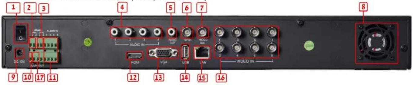
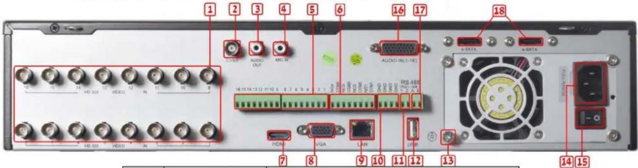
2.3.10 Rear Panel Description(SA-24600)
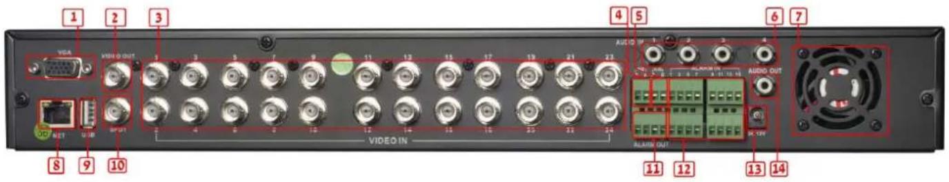
| Item | Name | Description |
| 1 | VGA | VGA output, connect to monitor |
| 2 | Video out | Connect to monitor |
| 3 | Video in | Video input channels 1-24 |
| 4 | P/Z | Connect to speed dome (RS485 PTZ cameras) |
| 5 | K/B | Connect to keyboard |
| 6 | Audio in | 4 CH auxiliary audio input |
| 7 FAN For cooling the device | ||
| 8 | NET | Network port |
| 9 | USB | Connect the USB mouse or an external USB device |
| 10 | Spot | Connect to monitor with no menu display |
| 11 | ALARM OUT | 1-ch relay output. Connect to external alarm. |
| 12 | ALARM IN | Connect to external sensor1-16 |
| 13 | POWER INPUT | DC12V |
| 14 | Audio out | Auxiliary audio output |
Digital Video Recorder User Manual
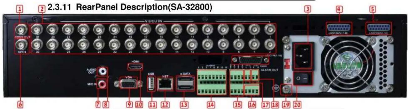
| Item | Name | Description |
| 1 Video out Connect to monitor | ||
| 2 | Video in | Video input channels(1- 32-ch) |
| 3 | POWER INPUT | 110VAC or 230VAC |
| 4 | Loop Out (17-32) | Video out (with a 16 channel plug) for channels 17-32. |
| 5 | Loop Out (1-16) | Video out (with a 16 channel plug) for channels 1-16. |
| 6 Spot | Connect to monitor with no menu display | |
| 7 MIC IN | Auxiliary audio input for personal microphone | |
| 8 | Audio out Auxiliary audio output | |
| 9 | VGA | VGA output, connect to monitor |
| 10 | HDMI | HDMI output, connect to monitor |
| 11 | USB | Connect the USB mouse or an external USB device |
| 12 | LAN | Network port |
| 13 | e-SATA | Connection for external e-SATA HDD for backp |
| 14 | ALARM IN | Connect to external sensor1-16 |
| 15/16 | ALARM OUT/Ground | 4ch relay output. Connect to external alarm. |
| 17 | P/Z | Connect to speed dome |
| 18 | K/B | Connect to keyboard |
| 19 | Ground | Grounding (also for the alarm in ground connection) |
| 20 | POWER SWITCH | Switch on/off |
| 21 | Audio in | 16 CH Audio input (with a 16 channel plug) |
Digital Video Recorder User Manual
2.3.12 RearPanel Description(SA-8200D1SDI)
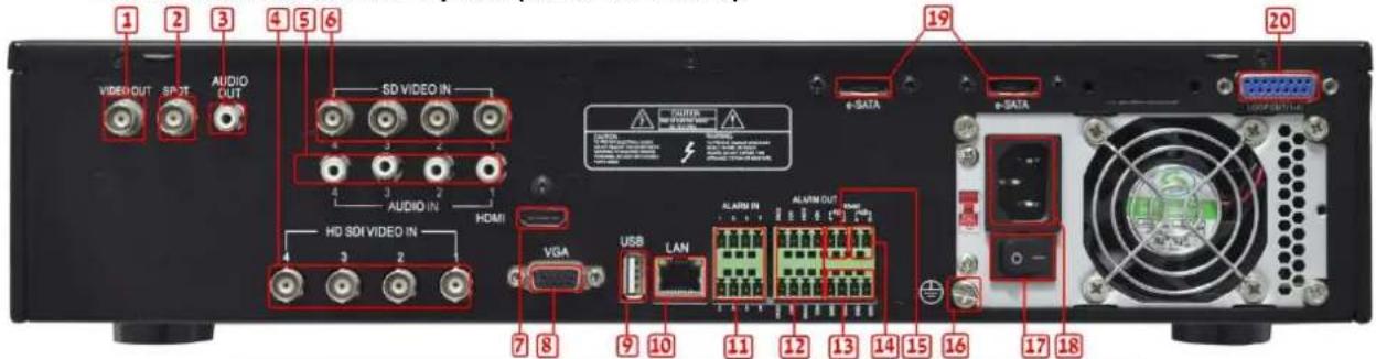
| Item | Name | Description |
| 1 | Video out | Connect to monitor |
| 2 | Spot | Connect to monitor with no menu display |
| 3 | Audio out | Auxiliary audio output |
| 4 | Video in | HD SDI Video input channels(1-4) |
| 5 | Audio in | 4 CH auxiliary Audio input |
| 6 | Video in | D1 or CIF Video input channels(1-4) |
| 7 | HDMI | HDMI output, connect to monitor |
| 8 | VGA | VGA output, connect to monitor |
| 9 | USB | Connect the USB mouse or an external USB device |
| 10 | LAN | Network port |
| 11 | ALARM IN | Connect to external sensor1-8 |
| 12/13 | ALARM OUT/Ground | 4ch relay output. Connect to external alarm. |
| 14 | K/B | Connect to keyboard |
| 15 | P/Z | Connect to speed dome |
| 16 | Ground | Grounding |
| 17 | POWER SWITCH | Switch on/off |
| 18 | POWER INPUT | 110VAC or 230VAC |
| 19 | e-SATA | Connection for external e-SATA HDD for backup |
| 20 | Loop Out (1-16) | Video out (with a 16 channel plug) for channels 1-16. |
Digital Video Recorder User Manual
2.3.13 RearPanel Description(SA-8200SDI)
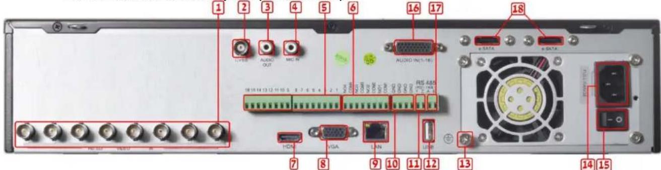
| Item | Name | Description |
| 1 | Video in | HD SDI Video input channels(1-8) |
| 2 | Video out | Connect to monitor |
| 3 | Audio out | Auxiliary audio output |
| 4 | MIC IN | Auxiliary audio input for personal microphone |
| 5 | ALARM IN | Connect to external sensor1-16 |
| 6 | ALARM OUT | 4ch relay output. Connect to external alarm. |
| 7 | HDMI | HDMI output, connect to monitor |
| 8 | VGA | VGA output, connect to monitor |
| 9 | LAN | Network port |
| 10 | Ground | Ground for alarm in |
| 11 | P/Z | Connect to speed dome |
| 12 | USB | Connect the USB mouse or an external USB device |
| 13 | Ground | Ground for DVR |
| 14 | POWER INPUT | 110VAC or 230VAC |
| 15 | POWER SWITCH | Switch on/off |
| 16 | Audio in | 16 CH Audio input (with a 16 channel plug) |
| 17 | K/B | Connect to keyboard |
| 18 | e-SATA | Connection for external e-SATA HDD for backup |
Digital Video Recorder User Manual
2.3.14 RearPanel Description(SA-16200SDI/SA-16400SDI)
| Item | Name | Description |
| 1 | Video in | HD SDI Video input channels(1-16) |
| 2 | Video out | Connect to monitor |
| 3 | Audio out | Auxiliary audio output |
| 4 | MIC IN | Auxiliary audio input for personal microphone |
| 5 | ALARM IN | Connect to external sensor1-16 |
| 6 | ALARM OUT | 4ch relay output. Connect to external alarm. |
| 7 | HDMI | HDMI output, connect to monitor |
| 8 | VGA | VGA output, connect to monitor |
| 9 | LAN | Network port |
| 10 | Ground | Ground for alarm in |
| 11 | P/Z | Connect to speed dome |
| 12 | USB Connect the USB mouse or an external USB device | |
| 13 | Ground | Ground for DVR |
| 14 | POWER INPUT | 110VAC or 230VAC |
| 15 | POWER SWITCH | Switch on/off |
| 16 | Audio in | 16 CH Audio input (with a 16 channel plug) |
| 17 | K/B | Connect to keyboard |
| 18 | e-SATA | Connection for external e-SATA HDD for backup |
Digital Video Recorder User Manual
2.4 Remote Controller
The remote requires two AAA size batteries. For installing the batteries open the battery cover on the Remote Controller, placetwo batteries according to the correct polarity marked on the remote (+ and -), then fasten the battery cover to back its place.
Notice: if the remote is not working follow those steps:
- Check batteries poles are according to the marking inside the remote and check the remote.
- Replace the batteries and check the remote.
- Check IR sensor is not covered and check the remote.
if you suspect the remote is malfunctioned contact your dealer to replace your remote control unit. The interface of remote controller is shown in Fig2.8 Remote Controller.
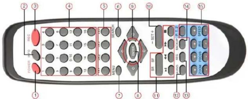
Fig 2.8 Remote Controller
Digital Video Recorder User Manual
| Item | Name | Function |
| 1 | Power Button | Soft switch off to stop firmware running. Do it before power off. |
| 2 | INFO Button | Get information about the DVR like firmware version, HDD information |
| 3 | REC Button | To record manually |
| 4 | Digital Button | Input digital or choose camera |
| 5 | Multi-Screen Button | To choose multi-screen display mode |
| 6 | SEARCH Button | To enter search mode |
| 7 | MENU Button | To enter menu |
| 8 | ENTER Button | To confirm the choice or setup |
| 9 | Direction Button | Move cursor in setup or pan/tilt/zoom PTZ |
| 10 | +/- Button | To increase or decrease the value in setup |
| 11 | Playback Control Button | To control playback, Fast forward/rewind/stop/single frame play |
| 12 | AUDIO Button | To enable audio output in live mode |
| 13 | Auto Dwell Button | To enter auto dwell mode |
| 14 | BACKUP Button | To enter backup mode |
| 15 | PTZ Control Button | To control PTZ camera: Move camera/zoom/focus/iris/speed control |
Operation processes with remote controller to control multi-DVR systems:
The device ID of the DVR can be changed. The default device ID is 0 (DVR and remote). To use the remote controller for a single DVR, don't reset the device ID, You can operate the DVR (with ID=0) directly. In case of multiple DVR systems follow these steps:
Step1: Activate remote controller to control DVR: enable DVR: point the IR led of the remote controller to the IR receiver on the front panel of the DVR. Press the number key 8 twice. Input device ID (Range from: 0-65535) with other digital number: 0-9. Press the ENTER button to confirm.
Step2:User maychange the device ID of the DVR:main menu =>System configuration=>Basic configuration=>device ID. It is not recommended to set other DVRs with the same device ID if it is in the same room. Please note that longer IDs are less convenient to operate.
Step3: To cancel controller DVR connection: aim the IR remote controllers led to the IR receiver that on the front panel, press the number key 8 twice, then input the device ID that needs to be cancelled from controlling, press ENTER button to confirm. After that, the DVR will not be controlled by that remote controller.
Digital Video Recorder User Manual
The "small 1U" DVR models contain the small remote controller.
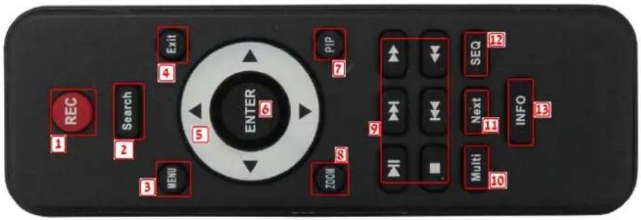
| Item | Name | Function |
| 1 | REC | Start or stop manual recording |
| 2 | SEARCH | Go to the search screen |
| 3 | MENU | Go to themain menu |
| 4 | Exit | Go back (without saving, the same as cancel) |
| 5 | Arrows | Move cursor (menu) or move (PTZ mode) |
| 6 | ENTER | confirm the choice or setup |
| 7 | PIP | Start or stop picture in picture mode |
| 8 | ZOOM | Zoom mode (ON/OFF) |
| 9 | Play control | During playback controls the movie |
| 10 | Multi | Multi-screen display mode (ON/OFF) |
| 11 | NEXT | Go to next selection |
| 12 | SEQ | Sequence mode (ON/OFF) |
| 13 | INFO | Go to theINFO menu |
Digital Video Recorder User Manual
2.5 Control with Mouse
2.5.1 Connect Mouse
The DVR supports USB mouse through the ports on the rear panel, please refer to Fig2.8.
Notice: If mouse is not detected or doesn't work:
- Make sure the mouse is plugged to the correct USB mouse port not the USB port2. Replace the mouse
2.5.2 Use Mouse
In live:
Double-click (left button) on one camera screen for full screen display. Double-click again to return to the previous screen display. Click right button to show the control bar at the bottom of the screen. Here are all control and setup. Click right mouse again to hide the control bar.
In setup:
Click left button to enter or accept. Click right button to cancel, or to return to the previous menu. To input a value, move cursor to the blank area and click left button once. An virtual keyboard will appear as in Fig2.9. It supports digitals, letters and symbols input.
Some values can be modified by the wheel, such as time. Move the cursor above the value, and roll the wheel to change the value.
Mouse drag; i.e. Set motion detection area: click customized, hold and drag to set motion detection area. Set schedule: hold and drag left button to set schedule time
In playback or backup:
Click left button to choose the options. Click "X" button to return to live mode.
![1 2 3 4 5 6 7 8 9 0 Backspace q w e r t y u i o p [ ] \ a s d f g h j k l ; ' Enter Shift z x c v b n m . , / / Esc - =](/content/2026/05/1068066/images/83dce810fffdc98a7c2330addc9a6b585dbbd97bfbb8311da58ac400be73fc3c.jpg)
Fig 2.9 virtual keyboard
In PTZ control:
Click left button to choose the buttons to control the PTZ. Click right button to return to live.
Notice:Mouse is the default tool in all the operation below unlessindicated otherwise.
Digital Video Recorder User Manual
3 Basic Function Instruction
3.1 Power On/Off
Before you power on the unit, please make sure all the cables are connected properly.
3.1.1 Power on
Step1: Plug in the power; switch on the power button (16-channel DVR only)
Step2: The device will start loading, and the power indicator will have blue color.
Step3: Before loading the camera view, a WIZZARDwindow will be pop-up and you could changethe time zone, time setup, network configuration, record configuration, disk management and more. User may or may not perform initial setup here or perform the setup from the menu as described on the relevant chapters. The setup Wizard is optional, to skip this step click on the "Exit" button. To disable the wizzardmark the option "startup wizzard" on the first page of the startup.
Notice: this serial device displays the menu either on VGA monitor or on the BNC monitor. To switch between the two outputs press the "ESC" button until you hear a long beep.
If there is no display or you can only see the cameras without the main menu after clicking the right button on the mouse press the "esc" button until a beep sounds. The VGA and video out (BNC) displays will switch.
3.1.2 Power off
You can power off the device by using remote controller, keyboard or mouse.
By remote controller: Press the "Power" button, the Shutdown window will appear, click "OK", the unit display a message on the screen, "it is now safe to unplug the DVR". Now you may disconnect the power line.
By keyboard and mouse:Step1: enter the Menu,

then select "System Shut Down" icon, the Shutdown window will appear, click OK, the unit display a message on the screen, "it is now safe to unplug the DVR". Now you may disconnect the power line.
Digital Video Recorder User Manual
3.2 Login
You can login and logout from the DVR system. After logout the user cannot operate except changing the multi-screen display.
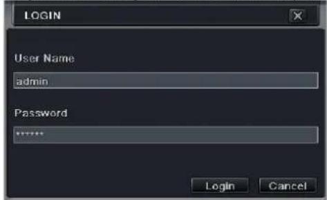
Fig 3-1 Login
Notice: The default user name is "admin" and the password is "123456"
Tochange thepassword, or to add or deletea user refer to Fig 4.7 "User management configuration".
3.3 Live preview

natural_image
Grid of six identical panels showing a road scene with trees and vehicles, no visible text or symbols.Fig 3-2 live preview interface
| Symbol | Meaning |
| Green | Manual record |
| Yellow | Motion detection record |
| Red | Sensor Alarm record |
| Blue | Schedule record |
Digital Video Recorder User Manual
3.3.1 Live playback
Click Play button to playback recordings. You can change settings by clicking on the buttons on screen.
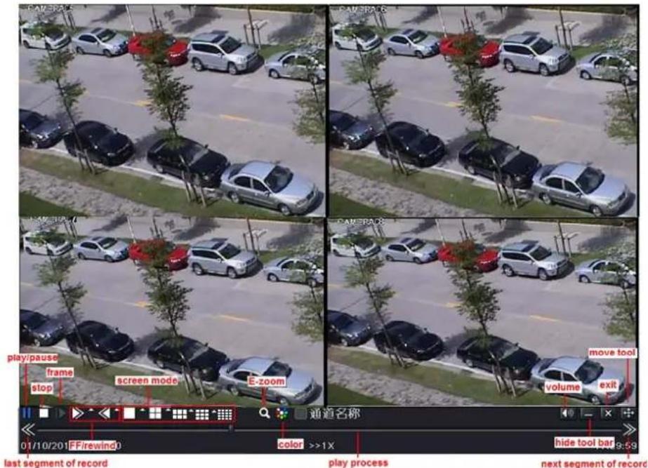
Fig 3-3 live playback
Digital Video Recorder User Manual
4 Main menu setup guide
Click right mouse or press ESC button on the front panel: the control bar will appear on the bottom of the screen, refer to Fig 4-1:

Fig 4-1 main menu toolbar
Click the icon beside "screen mode" to select the channels. There is an option for 6/8/13 channels with a main channel in the middle of the screen. You can arrange the order by drag and drop for the live display.
Dwell: this mode is used to display a 1/4/6/9/16 picture-screen that alternate every few seconds. To modify the settings go to main menu=>setup=>live=>main monitor.
Color: this mode is used to adjust the color of the live pictures.
E-Zoom: this mode is used to digitally magnify an image on live or recorded data: Left click the picture, right click and select Zoom. Simply press left mouse and drag the picture to view different parts of the image. Double-click the left mouse to exit E-Zoom mode.
Volume: this mode is used to mute or unmute and to select the audio channel if the audio out is connected to an amplified monitor.
PTZ: this mode is used to control pan/tilt/zoom and to access the menu of some smart PTZcameras. The control will change rotation position, speed of the dome and start track, auto scan or cruise in this interface. Refer to PTZ manual for more details.
Snap: (NE series) click this button to create a snapshot of the live cameras. These pictures will be saved on the SATA disk.
Record: this mode is used to start or stop continues record.
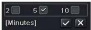
Playback: this mode is used to start playback of the latest2, 5 or 10 minutes recorded on the DVR =>
Move tool: this mode is used to movethe menu.
PIP: All models have PIP (picture in picture), activated from the taskbar(Screen mode)
Function menu: this mode is used to reach the main menu as Fig 4-2; you can also press MENU button on the front panel or operate with remote controllertodisplay the main menu. Click Setup icon will pop-up the configuration menu:
Digital Video Recorder User Manual
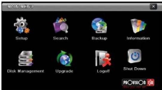
Fig 4-2 main menu
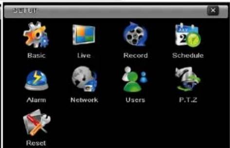
configuration menu
4.1 Basic configuration
The basic configuration has three sub menus: system, date& time and DST.
4.1.1 System
Step1: enter into system configuration=>basic configuration=>system; refer to Fig 4-3:
Step2: in this interface you can setup the device name, device ID, video format, max network users, VGA resolution and language. The definitions for every parameters display as below:
Device name: the device name can be displayed on the client end or CMS; which helps recognizing the device remotely.
Video format: there are two modes: PAL and NTSC. Selection of the video format must be identical to that of cameras.
![TANTIC System Date & Time DST Device Name FDVR Device ID 0 Video Format NTSC Password Check ✓ Show System Time ✓ Max Online Users 18 Video Output VCA 1624x768 Language English Logout After [Minutes] Never Startup Wizard ✓ Not Display When Logout Default Apply Exit](/content/2026/05/1068066/images/ed732b8ffef4b26b22f7072d13bbee341c314c8c78fdd8a4dc64fd6ca05ae5e2.jpg)
Fig 4-3 basic configuration-basic
Digital Video Recorder User Manual
Password check: enabling this option prompts user name and password before user can perform operations on the DVR.
Show System time: displays the time in live view.
Startup wizard: This option enables the wizardon startup.
Max network uses: set the maximumsimultaneous users via network connection.
VGA resolution: the resolution of live displayinterface, range from: VGA800*600, VGA1024*768, VGA1280*1024and CVBS.
Note : When switching between VGA and CVBSconnect to relevant monitor. (Also see 3.1.1)
Language: setup the menu language.
"Not Display When Logout": an option to hide all live channels before logging inlocally.
Note: after changing the languageor video output, the device willreboot.
4.1.2 Time & date
System configuration=>basicconfiguration=>time&date; refer to Fig 4-4.
Set the date format, time format, time zone in this interface; mark "sync time with NTP server" to refresh NTP server date or adjust system date manually.
Reset default setting; click the "default" button and then "apply" button to save the setting. click the "exit" button to exit current interface.
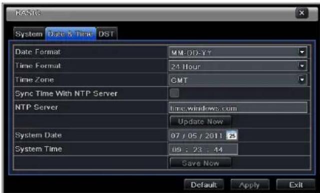
Fig 4-4 basic configuration-time & date
Digital Video Recorder User Manual
4.1.3 DST
System configuration=>basic configuration=>DST; refer to Fig 4-5:
In this interface you can enable daylight saving time, set the DST time offset, mode, start & end month/week/date.
Reset default setting; click the "default" button and then "apply" button to save the setting. Pressthe "exit" button to exit current interface.
![BASIC System Date & Time DST Daylight Saving Time Time Offset [Hours] 1 Mode Week Date From 01 / 01 / 2008 25 00 : 00 : 00 Until 01 / 01 / 2008 25 00 : 00 : 00 Default Apply Exit](/content/2026/05/1068066/images/2700099988514d92706e5bc84c851c87ebac3275dc29b9f98b3014594aa475fc.jpg)
Fig 4-5 basic configuration-DST
4.2 Live configuration
The live configuration has four submenus: live, host monitor, Spot and mask.
4.2.1 Live
This option is used to change camera name, adjust colors: brightness, hue, saturation and contrast.
Step1:System configuration=>live configuration=>live; refer to Fig 4-6:
Note: Clicking on acamera Name will pop up a soft keyboard. Now you can change the camera name.
Step2: if you unmark camera name the name will be hidden.
Digital Video Recorder User Manual
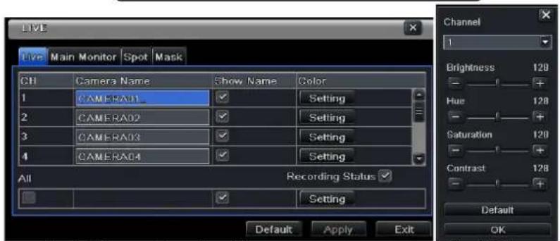
Fig 4-6 live configuration→live
Fig 4-7 live-color adjustment
Step3: clicking the "setting" button will pop-up a window (Fig 4-7) in this interface, you can adjust brightness, hue, saturation and contrast in live. The "default" button will restore the DVR to default live setting, click "OK" button to save the setting.
Step4: you can setup all channels with same parameters bymarking "all", and then "Apply".
4.2.2 Main monitor
System configuration=>live configuration=>main monitor; refer to Fig 4-8. Select group size: 1×1,2×2,2×3,3×3,4×4 and channels on each group.
Dwell time: the time interval for a picture group before switching to the next group.
After selecting the split mode setup the picture groups.
Click button to setup the previous channel groups of dwell picture.
![Live Main Monitor Spot Mask Display Mode 2X2 1/4 Channel 1 Channel 2 Channel 3 Channel 4 Dwell Time[3] 5 Max Group 4 .Current Group 1 Default Apply Exit](/content/2026/05/1068066/images/a9ed7635226b679939f8d5f8ca5c4aac2b129e12281939e666b0ea9cc61f8c72.jpg)
Fig 4-8 live configuration-host monitor
Digital Video Recorder User Manual
Click ▶ button to set the next channel group.
Step5: click "default" button to resort default setting; click "apply" button to save the setting; click "exit" button to exit current interface.
4.2.3 Spot
Step1: enter into system configuration→live configuration→Spot; refer to Fig 4-9:
Step2: select split mode: 1×1 and channel
Step3: dwell time: the time interval for a certain dwell picture display switching to next dwell picturedisplay
Step4: select the split mode and then setup current
picture group. Click button to setup the previous
channel groups of dwell picture. Click button to set the latter channel groups of dwell picture.
Reset default setting; click the "default" button and then "apply" button to save the setting. Press the "exit" button to exit current interface.
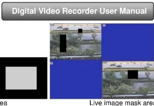
4.2.4 Mask
You can add up to three privacy mask areas on the live image picture, to block view and recording.
Setup mask area: click setting button, enter live image and press left mouse to create or move a privacy mask, refer to the picture on the next page. Pressthe "Apply" button to save your setting.
Delete mask area: double click on the mask area you want to delete. Click Apply button to save the setting.
![Live Main Monitor Spot Mask Display Mode 1X1 1/16 Channel: 1 Dwell Time[S] 5 Max Group:16 .Current Group:1 . Default Apply Exit](/content/2026/05/1068066/images/3c443027f6b0aaaad3a3ba1c9904464e1b3a565c9e5dde085fe7526057c6fe60.jpg)
Fig 4-9 live configuration-Spot
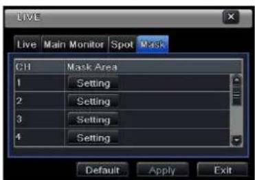
Fig 4-10 live configuration-mask
4.3 Record configuration
Record configuration includes six sub menus: enable, record bit rate, time, recycle record, stamp and snap for NE orHD series.
4.3.1 Enable
Step1: enter into system configuration→record configuration→enable; refer to Fig 4-11:
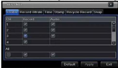
| Parameter | Meaning |
| Record | Record switch of every channels |
| Audio | Enable live record audio |
Fig 4-11 record configuration-enable
Step2: mark record, audio and record time to enable audio/video record.
Step3: user can setup all channels with the same parameters by marking "all", then "apply."
Digital Video Recorder User Manual
4.3.2 Record stream
Step1: go to system configuration→record configuration→record bit rate; refer to Fig 4-12:
Step2: setup rate, resolution, quality, encode and max bit stream
Step3: setup everychannel with the requiredparameters, or mark "All" and setto apply thechanges to all channels.
Reset default setting; click the "default" button and then "apply" button to save the setting. Pressthe "exit" button to exit current interface.
Note: if the rate value set is over high the maximum resources of the device, the value will be adjusted automatically.
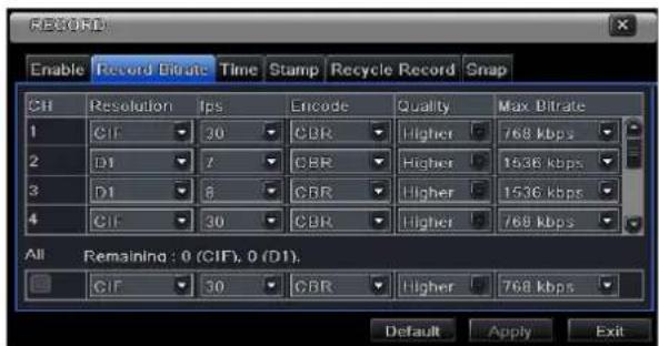
Fig 4-12 record configuration-record bit rate
| Parameter | Meaning |
| Rate | Range from: 1-30 (NTSC) 1-25(PAL) |
| Resolution | Support CIF, D1, and HD1 (D1, 12fps) |
| Quality | The higher the value is, the clearer the recorded image is. Six options: lowest, lower, low, medium, higher and highest. |
| Encode* | VBR and CBR |
| Max bit stream* | Range from: 64 Kbps, 128 Kbps, 256 Kbps, 512 Kbps, 768 Kbps, 1Mbps, 2 Mbps |
\*Only in NE or HD Series
4.3.3 Time
Step1: go to system configuration=>record configuration=>time; refer to Fig 4-13:
Pre-alarmrecord time: prerecord time before being triggered; (motion/sensor)triggering.
Post-alarm record: recording time after the alarm has stopped. There five options: 10s, 15s, 20s, 30s, 60s, 120s, 180s and 300s.
Digital Video Recorder User Manual
Expire time: the maximum time a recording will be in the system. If the set date is overdue, the record files will be deleted automatically. To setup all channels with the same parameters mark "all" and then click "apply".
Reset default setting; click the "default" button and then "apply" button to save the setting. Pressthe "exit" button to exit current interface.
![RECORD Enable Record Bitrate Time Stamp Recycle Record Snap CH Pre-alarm Record Time[S] Post-alarm Record Time[S] Expire[Days] 1 30 5X60 Never 2 30 30 Never 3 30 30 Never 4 30 30 Never All 30 30 Never Default Apply Exit](/content/2026/05/1068066/images/28d6c2e5ff54bec8e3f3391d35923252e4d2f1b81a33db8c30310784911f929b.jpg)
Fig 4-13 record configuration-time
4.3.4 Stamp
Stamp: Change the position of the camera name or the time stamp.
Step1: configuration=>record configuration=> stamp; refer to Fig 4-14:mark camera name, time stamp; click Setting button. Use cursor to drag the camera name and time stamp to the desiredpositions. To setup all channels with the same parameters mark "all" and then click "apply".
Reset default setting; click the "default" button and then "apply" button to save the setting. Pressthe "exit" button to exit current interface.
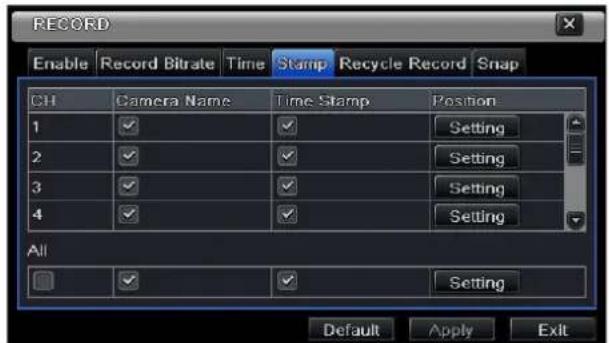
Fig 4-14 record configuration-stamp
Digital Video Recorder User Manual


Before repositioning after repositioning
4.3.5 Recycle record
System configuration=>record configuration=>recycle record; mark"recycle record" to enable recycle recording. When the disk is full the new files will overwrite the earliest files and keep recoding after the HDD is full; if You disable this function the DVR will stop recording when the HDD is full.
Reset default setting; click the "default" button and then "apply" button to save the setting. Press the "exit" button to exit current interface.
4.3.6 Snap
This option is used to set up Resolution, quality, snap shot interval and the number of pictures taken.
4.4 Schedule configuration
Schedule configuration includes three sub menus: schedule, motion and alarm.
4.4.1 Schedule
This table represents the days in a week from Sunday to Saturday, and on the top the 24 hours of a day. Click the grid to do relevant setup. Blue means checked area and gray means unchecked area.
Step1: enter into system configuration→schedule configuration→schedule; referring to Fig 4-15:
Digital Video Recorder User Manual
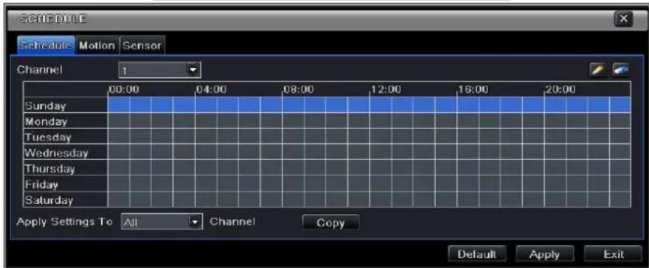
Fig 4-15 schedule configuration-schedule
Step2: select channel and double-click to pop up a window as Fig 4-16. Now you can edit week schedule:
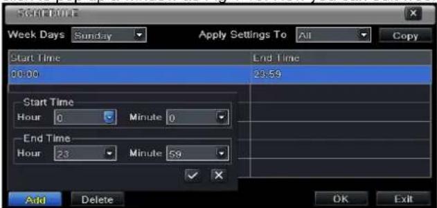
Fig 4-16 schedule-week schedule
- Press the "add" button to add a certain day schedule or press the "delete" button to delete the selected schedule; Copy: You can copy this schedule to other day by pressing "copy" then "ok".
Digital Video Recorder User Manual
Click "OK" button to save the setting; click "Exit" button to exit current interface.
- If the user wants to apply the schedule setting of certain channel to other or all channels, he needs to select channel and click "Copy" button.
4.4.2 Motion
Step1: enter into system configuration→schedule configuration→motion; refer to Fig 4-17:
Step2: the setup steps of motion are Similarto theschedule;Refer to 4.4.1 Schedule for details.
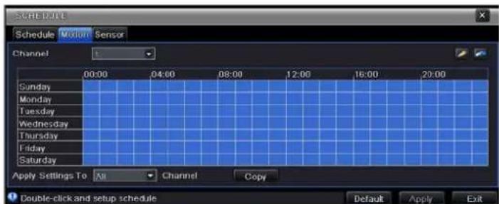
Fig 4-17 schedule configuration-motion
Note: the default schedule of motion detection is full-selected, that is, the color of schedule setting interface is blue.
4.4.3 Sensor
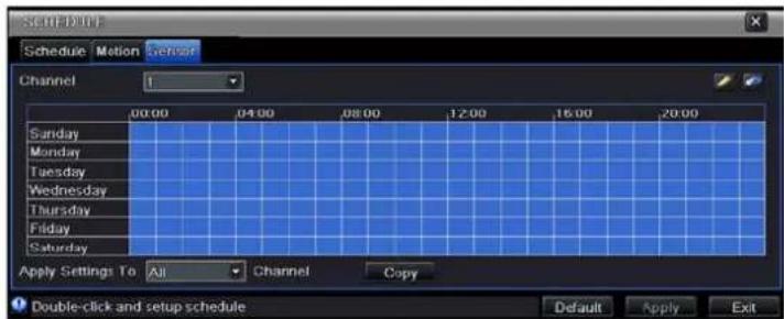
Step1: enter into system configuration→schedule configuration→alarm; refer to Fig 4-18:
Step2: the setup steps of alarm are Similarto the schedule; Refer to 4.4.1 Schedule for details.
Note: the default schedule of motion detection is full-selected, that is, the color of schedule setting interface is blue.
Fig 4-18 schedule configuration-sensor
Digital Video Recorder User Manual
4.5 Alarm configuration
Alarm configuration includes five sub menus: sensor, motion, video loss, other alarm and alarm out.
4.5.1 Sensor
Sensor includes three sub menus: basic, alarm handling and schedule.
- Basic
system configuration =>alarm configuration =>sensor =>basic;Refer to Fig 4-19: Enable sensor alarm and then set the alarm type according to triggered alarm type. Two option: NO and NC (Normally open/closed).
To setup all channels with the same parameters mark "all" then apply to save relevant setup to all channels.
Reset default setting; click the "default" button and then "apply" button to save the setting. Press the "exit" button to exit current interface.
- Alarm handling
Step1: enter into system configuration→alarm configuration→sensor→alarm handling; refer to Fig 4-20:
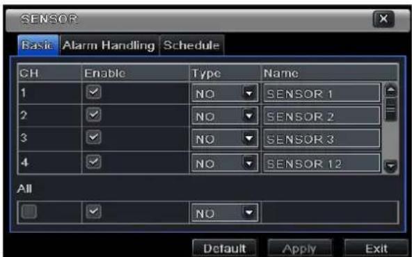
Fig 4-19 alarm configuration-sensor-basic
- Alarm handling
system configuration =>alarm configuration =>sensor =>alarm handling; refer to Fig 4-20: select hold time, click Trigger button, and a dialog box will pop-up as Fig 4-21:If Buzzer is selected, the sensor will prompt an alarm.
Note: there will be no alarm menu for DVRs that do not have an alarm system (for example the SA-4100HDX+ DVR model)
Digital Video Recorder User Manual
![SENSOR Basic Alarm Handling Schedule CH Holding Time[S] Trigger 1 10 Setting 2 10 Setting 3 10 Setting 4 10 Setting All 10 Setting Default Apply Exit](/content/2026/05/1068066/images/0987c41b5c39b279f2068fa89287a70b46c342b1234ba69331f55dcc7d7b2331.jpg)
Fig 4-20 alarm handling-triggerFig 4-21 alarm configuration-sensor-alarm handling
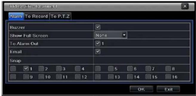
Full screen alarm: when alarm is triggered, there will pop up full screen alarm;
Email: Select this function. When an alarm is triggered, a notificationemail will be sent to thedesignatedemail box including trigger events, time, snap pictures, device name, ID camera name etc.
Snap (for NE or HD series): Select channels. When an alarm is triggered, the system will automatically save the captured pictures from the selected channel. If user activates the Email function, these pictures will also be sent to the designated email.
To alarm out: After selecting the channel, there will be triggered alarm out in the designated channel. Click OK button to save the setting; click Exit button to exit the current interface.
To record: Select recoding channels. It will record the camera when alarm is triggered. Click OK button to save the setting; click Exit button to exit the current interface.
To P.T.Z: set linked preset and cruise for alarm. User can select any channel or multi channels as linked channels. Click OK button to save the setting; click Exit button to exit the current interface.
To setup all channels with the same parameters mark "all" then apply to save relevant setup to all channels.
Reset default setting; click the "default" button and then "apply" button to save the setting. Press the "exit" button to exit current interface
Digital Video Recorder User Manual
- Schedule
System configuration =>alarm configuration =>sensor =>schedule;Refer to Fig 4-22: The setup steps of sensor schedule are similar with all schedules;Refer to 4.4.1 Schedule for details.
Note: the default schedule of sensor is to bealways on: the color of schedule setting interface is blue.
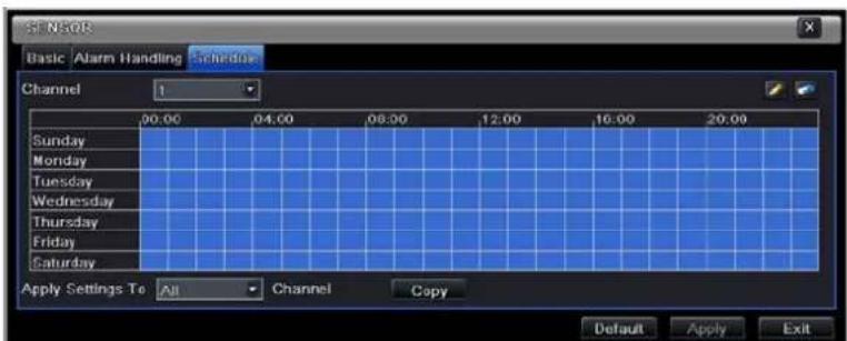
Fig 4-22 sensor-schedule
4.5.2 Motion
Motion includes two sub menus: motion and schedule.
- Motion
System configuration =>alarm configuration =>motion; refer to Fig 4-23: Enable motion alarm, set alarm hold time (time interval between two adjacent detective motions). If there is an additional motion detected during the interval period which is considered continuous movement; otherwise, it will be considered that those two adjacent detective motions are two different motion events. Click Trigger button, a dialog box will pop-up: The setup steps for motion trigger are similarto the alarm handling; Refer to Chapter 4.5.1 Sensor =>alarm handling for more details.
![MOTION Motion Schedule CH Enable Holding Time[S] Trigger Area 1 ✓ 10 Setting Setting 2 ✓ 10 Setting Setting 3 ✓ 10 Setting Setting 4 ✓ 10 Setting Setting All Default Apply Exit](/content/2026/05/1068066/images/5cd6f6e4bb3de45e6dc00fa1d9da44759dc9070e8f3c43290fb77d154d4ebbb0.jpg)
Fig 4-23 alarm configuration-motion
Digital Video Recorder User Manual
Next: click Area button, a dialog box will pop-up as Fig 4-24 a and 4-24b.
To set the sensitivity value (1-8) drag the slide bar in the Area interface, the default value is 6. The higher the value the higher the sensitivity to movement, meaning more events will be recorded. Due to the sensitivity is influenced by color and time (day or night), adjust its value according to the practical conditions; click 🏠 icon, set the whole area as detection area; click 📊 icon, the set detection area will be cleared; click 🔒 icon, user can test if the sensitivity value and motion area are suitable accordingly (refer to following picture); Click 🔒 icon, to save the setting; click ✕ icon, exit current interface.
Note: to set the area drag the mouse to the desired detection area, click icon to clear all set detection area firstly, and only thenset the area.

Fig 4-24b motion-area

Fig 4-24 motion-area
Digital Video Recorder User Manual
To setup all channels with the same parameters choose "all" then apply to save relevant setup to all channels
Reset default setting; click the "default" button and then "apply" button to save the setting. Pressthe "exit" button to exit current interface.
- Schedule
system configuration =>alarm configuration =>schedule; refer to Fig 4-25:the setup steps of alarm schedule are similar to those in 4.4.1
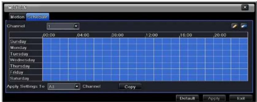
Fig4-25 alarm configuration-schedule
4.5.3 Video loss
System configuration =>alarm configuration =>video loss; refer to Fig 4-26:the setup steps of video loss trigger are similar to the alarm handling;Refer to Chapter 4.5.1 Sensor =>alarm handling for more details.
To setup all channels with the same parameters choose "all" then apply to save relevant setup to all channels.
Reset default setting; click the "default" button and then "apply" button to save the setting. Pressthe "exit" button to exit current interface.
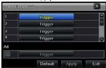
Fig 4-26 alarm configuration-video loss
Digital Video Recorder User Manual
4.5.4 Other alarm
Select system configuration→other alarm (as shown in Fig 4-27)
Disk full: You can choose the capacity of the disk storage and select the related alarm. If the disk is full, the system will perform according to the setup.
IP conflict: if there is an IP address conflict within the same network, the system will perform according to the setup.
Disconnect: if the system recognizes a network disconnection the system will perform according to the setup.
Disk Warning: if the disksends a warning the system will perform according to the setup
Disk Disconnected(an important improvement): when there is no recognized disk the system will perform according to the setup.
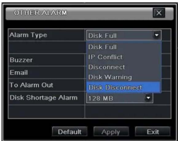
Fig4-27 other alarm
Reset default setting; click the "default" button and then "apply" button to save the setting. Press the "exit" button to exit current interface.
Select a hard disk in the list box. When the disk capacity is lower than that in the value, a message will appear on the lower right of the live image.
Digital Video Recorder User Manual
4.5.5 Alarm out
Alarm out includes three sub menus: alarm out, schedule and buzzer
- Alarm out
System configuration =>alarm out; refer to Fig 4-28: You can set relay alarm out name and select hold time (the interval time between the two adjacent alarms).
To setup all channels with the same parameters choose "all" then apply to save relevant setup to all channels.
Reset default setting; click the "default" button and then "apply" button to save the setting. Pressthe "exit" button to exit current interface.
![ALARM OUT Alarm Out Schedule Buzzer CH Relay Name Holding Time[S] 1 ALARM OUT 1 10 All 10 Default Apply Exit](/content/2026/05/1068066/images/36ab6a0a0408de468b2637e295ff9a36df8f269733af7ed084a8e8c1a6a9016c.jpg)
Fig 4-28 system configuration-alarm out
- Schedule
Configuration =>schedule;the setup steps of alarm out schedule are similar to those in4.4.1
Note: the default schedule of motion detection is set to always on: the color in the schedule is blue.
- Buzzer
Configuration => buzzer; mark Buzzer and set buzzer alarm hold time.
Digital Video Recorder User Manual
4.6 Network configuration
Network configuration includes four submenus: network, sub stream, Email and other settings.
4.6.1 Network
Step 1: Main menu =>system configuration =>network configuration =>network; refer to Fig4-29:
The defaultHTTP port is 80. If the value has changed, you need to add the port number after the IP address; if the HTTP port is set to 82, and the IP address is192.168.0.25the full address is: http://192.168.0.25:82 (both LAN and WAN)
The server port is the communication port.
If the option "Obtain an IP address automatically" is marked, the device will obtain the IP address, SubnetMask, Gateway and DNS servers from the DHCP (e.g. a router).
You can use PPPoE protocol to directly connect the DVR to anADSL modem. Mark the "PPPoE" checkbox, and add the user name and password, click "Apply" then "Test" to see if there is a problem with the data or connection.
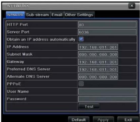
Tip: to connect multiple systems use consecutive IP and ports.
For example: use 10.0.0.95 with ports 95 and 6095, and 10.0.0.96 with ports 96 and 6096, and 10.0.0.97 with ports 96 and 6097.
Fig 4-29 network configuration-network
Digital Video Recorder User Manual
4.6.2 Sub stream

Fig 4-30 network configuration-sub stream
System configuration =>network configuration =>sub stream; refer to Fig 4-30:select fps, resolution, quality, encode and max bit rate
To setup all channels with the same parameters choose "all" then apply to save relevant setup to all channels.
Reset default setting; click the "default" button and then "apply" button to save the setting. Press the "exit" button to exit current interface.
Definitions and descriptions of Sub stream:
| Parameter | Meaning |
| FPS | Range from: 1-25 |
| Resolution | Support CIF |
| Quality | The quality of the clients' image. The higher the value is, the clearer the record image. Six options: lowest, lower, low, medium, higher and highest. |
| Encode | VBR and CBR |
| Max bit rate | Range from: 64/128/256/512/768 Kbps, 1 and 2 Mbps |
Digital Video Recorder User Manual
4.6.3 Email
system configuration =>network configuration =>email; refer to Fig 4-31
SMTP Server/Port: the name and port number of SMTP server. After selecting "This server requires a secure connection (SSL)", you can setup mail servers (such as Gmail/Yahoo/Hotmail) according to the e-mail providerrequirements
Note: Gmail SMTP server is "smtp.gmail.com", theport is 465 and the SSL Checkbox is marked [v].
Send address and password: sender's accountdetails.
Receive address: receiver's email address. Here you can add at most three e-mail addresses.
Click TEST button to test the validity of the mailbox.
Attaching image: when checked the mail sent will contain snap (also see 4.3.6).
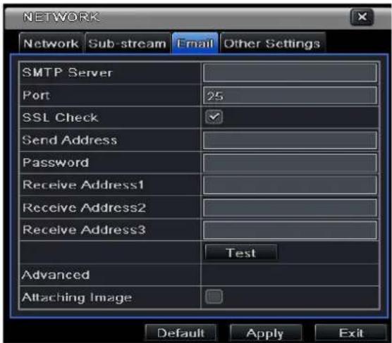
Fig 4-31 network configuration-email
4.6.4 Other settings
To enable the DDNS server option fill in theDDNS account location and validation. The host domain name is the final address of the registered website. Click TEST to test if the information is correct and the service works.
Reset default setting; click the "default" button and then "apply" button to save the setting. Pressthe "exit" button to exit current interface.
Digital Video Recorder User Manual
![NETWORK Network Sub-stream Email Other Settings DDNS DDNS Type www.dvrdydns.com User Name Password Host Domain DDNS Update [Hours] 3 Test UPnP Default Apply Exit](/content/2026/05/1068066/images/bb1b66d2c6e9f9dcca83151e5deb598b54c1ab7fd483cae96fd9da4b8b397ee3.jpg)
Note: The domain name server selected makes it possible to usea domain name forthe DVR instead of using the DVR's "external" IP address. First register for a user name and password (at the DDNS website), and then apply for a domain name. After completing the registration (and only if the correct port forwarding rules are in effect) you will be able to access yourDVR from the internet. Simply write your domain name in the internet browser's address bar.
Fig 4-32 network configuration-other settings
Using UPnP:A technician may prefer to use UPnPto access the DVR remotely from the WAN: enable UPnP function in the user's router and the DVR. When accessing the DVR through IE, user can check the IP address by the following method: Double-click the "My Network Places" icon onthe desktop in PC, select "Show icons for networked UPnP devices" in the "Network Tasks" list box,a information window will pop up, click "YES" button, "Windows Components Wizard" dialog box will pop up as shown as below picture, press "Next" to continue. After finished the installation of configuring components, the UPnP icons will display. Users can double-click certain icon and check the IP address of the device.
Digital Video Recorder User Manual
If "Show icons for networked UPnP devices" can't display in the "Network Tasks" list box, please follow the below operation:
- Click "Tools"- "Folder options" (figure 4-33)
- Select the "Show common tasks in folders" in the "Tasks" check box to display the UPnP icon (figure 4-34)
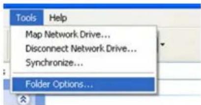
Figure 33
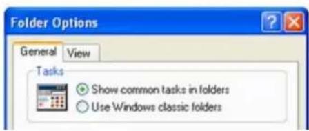
Figure 34
(a) To register a domain with Provision-ISR DDNS server follow these steps:
1) Visit our website: http://provision-isl-dns.com and register for a domain name by clicking "Registration" (figure 4-35)

Figure 35
Digital Video Recorder User Manual
2) Fill in the registration form, then click "Submit" (figure 4-36)
3) Fill in the host name you want to apply for. Now press "Request Domain", for example "home" (figure 4-37)
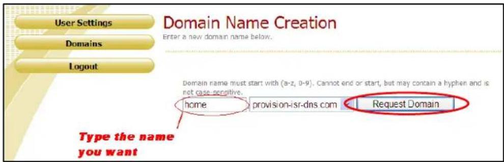
Figure 37
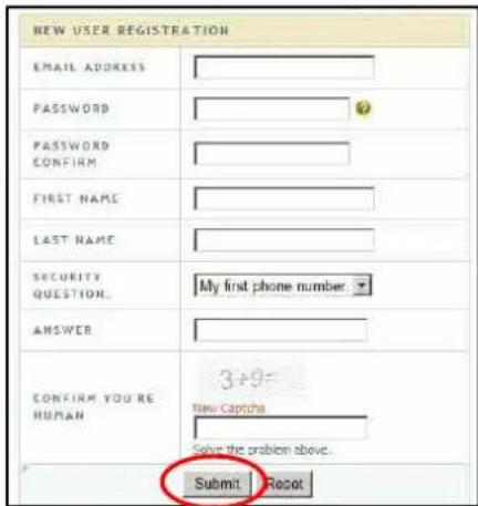
Figure 36
If there is no problem with the domain registration you will see the following message: "Your domain was successfully created." If you do not see this message, the domain name you requested is already in use and you will be requested to provide an alternate domain name (figure 4-37). You can create up to 35 domain records under a single account. The domain name is your DVR's address prefix, for example the domain "home" will appear as "home.provision-isr-dns.com".
Note: domain name is sometimes called host name.
Digital Video Recorder User Manual
User management configuration
Step 1: enter into system configuration =>user management configuration; refer to Fig 4-38:
Step 2: click Add button to display a dialog box as Fig 4-39:
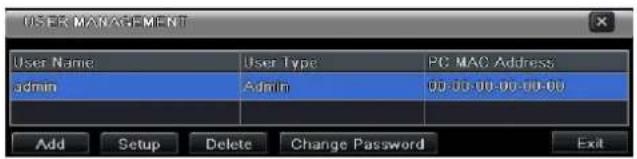
Fig 4-38 user-management
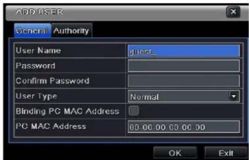
Fig 4-39 add-general
① General: Input user name, password; select user type: normal and advance, input the MAC address of the PC; click OK button. Then this user will be added into the user list box; click Exit button to exit the current interface.
Note: when the default value of binding PC MAC address is 0, the user is not boundtoa computer; the user can log to the DVR with that account only if the computer has a specific MAC address.
② Authority:
After adding a user, go to authority (Fig 4-40): In the authority interface, assign the operation limitations for that user. Click the Setup button to modify user name, user type and MAC binding address.
To delete a user choose that user in the user list box and then click "Delete" button. To change a password click the "Change Password" button and modify the password; click Exit button to exit the current interface (Fig 4-38)
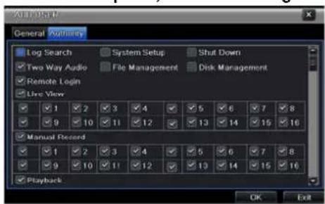
Fig 4-40 add user-authority
Digital Video Recorder User Manual
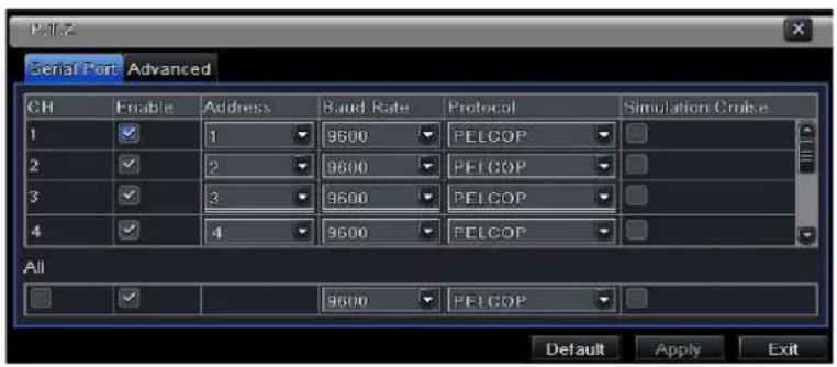
Fig 4-41 P.T.Z configuration-serial port
4.7 P.T.Z configuration
P.T.Z configuration includes two submenus: serial port and advance①Serial port
System configuration => P.T.Z configuration => serial port; Refer to Fig 4-41: mark "Enable" and then setup the value of that camera (address, baud rate and protocol according to the settings of the speed dome).
To setup all channels with the same parameters choose "all" then apply to save relevant setup to all channels.
Reset default setting; click the "default" button and then "apply" button to save the setting. Press the "exit" button to exit current interface.
"Simulative Cruise": the DVR will send presets in loop and not send the single "Cruise" command
Definitions and descriptions of network stream:
| Parameter | Meaning |
| Address | The address of the PTZ device |
| Baud rate | Baud rate of the PTZ device. Range form: 110, 300, 600, 1200, 2400, 4800, 9600, 19200, 34800, 57600, 115200, 230400, 460800, 921600. |
| Protocol | Communication protocol of the PTZ device. Range from: NULL, PELCOP, PELCOD, LILIN, MINKING, NEON, STAR, VIDO, DSCP, VISCA, |
Digital Video Recorder User Manual
SAMSUNG, RM110, HY, N-control.
③ Advance
Configuration => P.T.Z configuration =>advance;Refer to Fig 4-42: click preset "Setting" button to see a dialog box as Fig 4-43:
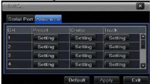
Fig 4-42 P.T.Z configuration-advance
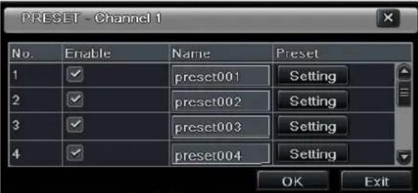
Fig 4-43 advance-preset setting
a. in the preset set interface, while clicking Setting button, a dialog will pop-up as Fig 3-44:

Digital Video Recorder User Manual
Fig 4-44 preset set-setting
b.user can control the dome rotates up, up left, down, right down, left, left down, right and up right and stop rotating; adjust the rotate speed and the value of zoom, focus and iris of the dome;
c. select the serial number of the preset point. If relevant click button to enable the PTZ wiper and click button to enable the PTZ light.
Note: PTZ must support wiper and light for these two functions to work. These two buttons are available only when using PELCOP or PELCOD.
Click Save button to save the settings, click — icon to hide the tool bar, right-key can remerge it; click ✗ icon to exit the current interface.
d. in the preset interface, click OK button to save the setting; click Exit button to exit current interface without saving. Step 3: in the Advance interface, click the cruise "Setting" button, a dialog box will pop-up as in Fig 4-45:
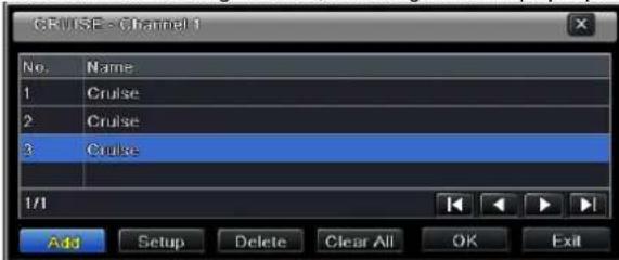
Fig 4-45; cruise set
a. click the "Add" button to add cruise line in the list box (max 8 cruise line can be added); select a cruise line and click Setup button to see a dialog box as Fig 4-46:
b.click Add icon + to set the speed and time of preset point; select a preset point and then click Delete icon 📁 to delete that preset point; click the "Modify" icon 🎨 to modify the setting of the highlighted preset point. Click ↑ ↑ ↓ ↓ to
Digital Video Recorder User Manual
adjust the position of the preset point. Click Preview button to preview the cruise line; click OK button to save the setting; click Exit button to exit current interface without saving.
c. select a preset point in the cruise line list box. Click "Delete" button to delete that cruise line; click Clear all button to clear all cruise line from the list box; click OK button to save the setting; click Exit button to exit current interface.
Step4: in the Advance interfaceclick "Setting" button, a dialog box will pop-up as Fig 4-47:
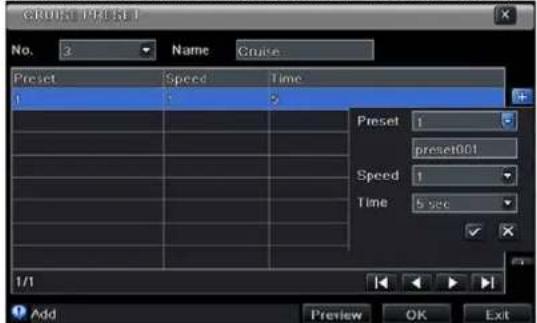
Fig 4-46 cruise set-modify cruise line
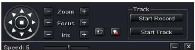
Fig 4-47 track setting
d. user can control the dome rotation up, up left, down, right down, left, left down, right and up right and stop rotating; adjust the rotate speed and the value of zoom, focus and iris of the dome; click Start Record button to record the move track of PTZ; click this button again can stop record; click Start track button to play recorded track; click this button again can stop play.
e.click — icon to hide the tool bar, right-key can remerge it; click ✗ icon to exit the current interface without saving.
4.8 Advanced
Advanced configuration includes three submenus: reset, import/export and Block/Allow list for the NE or HD series.
Digital Video Recorder User Manual
4.8.1 Reset
Reset all settings the device will reboot, please note: perform the reset only after consulting with a technician.
4.8.2 Import/Export
User can export the data files into mobile storage devices as backup function, and then import specified data files from mobile storage device to DVR.
4.8.3 Block/Allow list
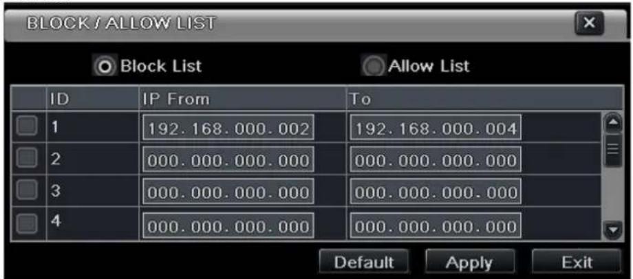
Fig 4-48 Block/Allow list
Theauthorized user can block/allowusers from accessing the DVR according to their IP address. For example,if authorized user wants to blockcomputer userswith IP addressesfrom 196.168.000.002 to 196.168.000.004, authorized user can markBlock list, and then input such IP address segment. After clicking Apply the settings will be saved. If authorized users allow computer users withina certain IP address segment to access DVR, they can markAllow-list, and add the IP to the allow list. All other users will be blocked.
Digital Video Recorder User Manual
5 Record search & playback and backup
Search configuration includes four submenus: time search, event search, file management and image.
5.1 Time search
Search configuration =>time search; Refer to Fig 5-1:
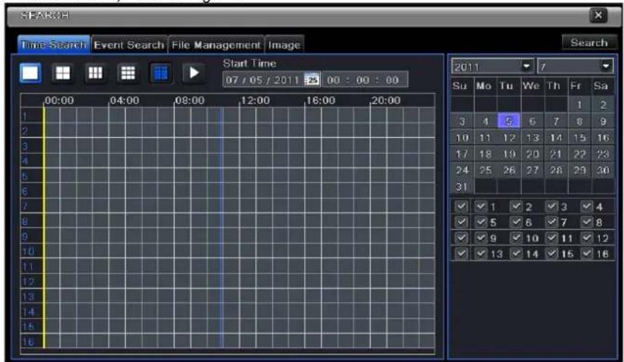
Fig 5-1 Search configuration-time search
select channel/s, screen display mode, (highlighted date in the calendar means there are recording on that date). Select the date, press the "Search" button, click on the time grid to set the play start time or input play record time manually.
Digital Video Recorder User Manual
Note: the vertical column represents the time (hours), while the horizontal column represents the channels.
Another option is to click Play

button to playback record on the main screen to start play of last 30 minutes.
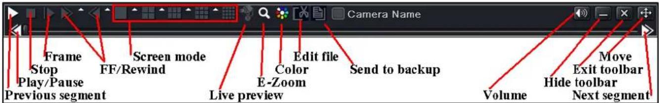
Note: when the monitor resolution is VGA800*600, the time search interface will appear a hide button, click this button, the whole interface can be expanded.
- During playback edit file 📄 to send a short movie for quick backup 📋 (minimum length is one minute)
• DVRs with 8 or more channels have 4CH live preview when playback, activated from the taskbar
5.2 Event search
Configuration =>event search; refer to Fig 5-2:
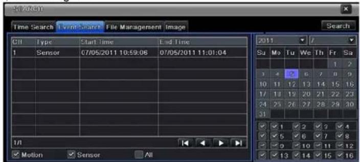
Digital Video Recorder User Manual
Fig 5-2 Search configuration-event search
Click on the "Search" button to display the event information in the event list box. Here you can select the date and channel. You can choose events by motion, sensor or All accordingly. Double clicking on a certain record file will start playback.
Note: when the monitor resolution is VGA800*600, the event search button will appear as a small line. Place the mouse on the line then click this button to expand the whole interface.
5.3 File management
Search configuration =>file management; Refer to Fig 5-3:

Fig 5-3 Search configuration-file management
After clicking the "Search" button, the files will be displayed in the file list box. You can make the selection according to date and channel number accordingly.
Lock: select a file and click the "Lock" button to lock this file, that file will not be deleted until unlocked.
Digital Video Recorder User Manual
Unlock: select a locked file and click the "Lock" button to unlock this file.
Delete: select an unlocked file and click Delete button to delete this file. After selecting the "All" button user can lock, unlock or delete all files in the file management column. Double clicking an unlocked item will playback the event.
5.4 Image
This option is used to set start, end time and channels to search the captured images and save, lock or delete these images. The capacity set is 2000 images which can be saved in the SATA disk. If there are more images saved in the SATA, those additional images will override prior images (first in first out). Double clicking an image will start playback from the time the image captured.
5.5 Backup
This unit supports backup by built-in SATA DVD Writer with USB Flash. User can also backup remotely using IE or safari browser via internet. Refer to 7.3.2 Remote backup. Enter backup configuration; refer to Fig 5-4:
Set the start & end time, select channels, and click on thesearch button, the searched data will be displayed on the data backup list. Selecting a data file or marking"All" to select all data files then clickingthe "Backup" button will display thebackup information window. In the backup information window you can check the relevant information of the backed up files, the storage type, the file type, etc. Clicking the"Start" button will start the backup.
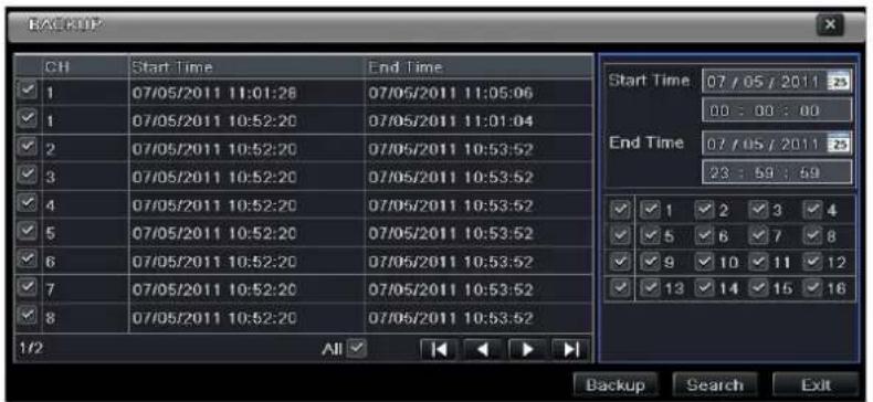
Fig 5-4 backup configuration
Digital Video Recorder User Manual
6 Manage DVR
6.1 Check system information
Display the system information. This includes five submenus: system, event, log, network and online user.
6.1.1 System information
In this interface, user can check the hardware version, MCU version, kernel version, device ID, etc.
6.1.2 Event information
This option is used to check data about recorded events according to the set date.
Note: if there are overlapping files, a “+” character will show behind the channel ID.
6.1.3 Log information
This option is used to check relevant log information according to time and date.
Data files can be exported into a mobile storage device such as a USB pen-drive.
6.1.4 Network information
This option is used to check relevant parameters of the network.
6.1.5 Online information
This option is used to check the details of the current connection of online users.
Refresh: refresh the current interface.
Disconnect (NE series): the administrator authorized to disconnect the client terminal. After disconnected this way the PC will not be able to access the device for the next five minutes.
6.1.6 Recording data: displays frame rate for each channel, HDD status, HDD usage, current record mode (motion, manual, alarm, schedule); display Video format: PAL or NTSC
Digital Video Recorder User Manual
6.2 Manual alarm
This option is used to activate the alarm manually, this option also activates the buzzer.
6.3 Disk management
1. Format the disk
Go to "disk management"
Note: please format the hard disk before startinga recording. If the disk is not formatted, it will show the status of the disk-free space, and total space show OM at the bottom of screenbut the DVR will not record.
Clicking the "Refresh" button will refresh the disk information in the list. Set the property of a disk and click Apply. To formata hard disk(s), select therelevant drives on the list and click "Format".
Note: all recorded files in the hard disk will be lost after formatted.
2. Advanced
User may check model, S/N, firmware, health status of the disk in this interface. User also can monitor the temperature, internal circuit, dielectric material of the disk, analysis the potential problems of the disk and warn so as to protect its data.
6.4 Upgrade
At present, the DVR only supports update via USB. Download the software from your vendor and make sure it matches the DVR. You can check the USB information in Disk management; the USB must be recognized and formatted (FAT32).
Upgrade method: theuser needs to copy the upgrade software into the USB storage device and then connectit to the USB port. Enter Menu→Upgrade, the upgrade software name is displayed in the upgrade list box, select that software and then click upgrade button. It will upgrade automatically. Never disconnect the power line during backup! Please wait for a while when the system is rebooted.
6.5 Logoff
Click Log off icon, a log off dialogue box will popup, click OK to log off. Click any button and the login menu will appear.
Digital Video Recorder User Manual
7 Remote Surveillance
7.1 IE Remote Surveillance
To view the DVR from a network it must be connected to a modem or router through the LAN/WAN. The network setup should be done accordingly. Please refer to 4.6 Network Setup. This DVR supports IE browser, Firefox and Chrome on Windows XP and Vista platform.
7.1.1 On LAN
Step 1: Enter into the DVR's Main Menu→Setup→Network interface to input IP address, Subnet Mask, etc. If using DHCP, enable DHCP in both the DVR and the router.
Step 2: Enter Record Setup to set network video parameters like resolution, frame rate etc.
Step 3: Open IE on a computer on the same network. Input the IP address of the DVR in IE address bar and press enter.
Step 4: IE will download ActiveX component automatically. Enter the username and password in the subsequent window
Notice: If you use an HTTP that is not 80, you will need to add the port number after IP address. For example, set HTTP port as 82, need input IP address like 192.168.0.25:82
User name and password here are the same with that used on the DVR. The default is admin and 123456.
7.1.2 On WAN
There are two ways for the DVR to connect to internet.
1. Connect the DVR to internet through router or virtual server
Step 1: Enter into the DVR's Main Menu→Setup→Network interface to input IP address, Subnet Mask, etc. If using DHCP, please enable DHCP in both the DVR and router.
Step 2: Forward IP address and port number in Virtual Server setup of the router or virtual server. Configure the firewall to allow accessing the DVR. (If the user has enabled the UPnP function in both the DVR and router, he can skip this step.)
Step 4: If users want to utilize dynamic domain name, please apply for a domain name in a DNS server supported by the DVR or router. Then add to the DVR or router.
This DVR supports www.dns2p.com, www.meibu.com, www.dyndns.com and www.no-ip.com.
Step 5: Open IE browser, input IP address, or dynamic domain name and enter.
Digital Video Recorder User Manual
Step 6: IE will download ActiveX automatically. Then a window pops up and asks for user name and password.Input user name and password correctly, and enter to view.
Note: If you cannot download and install ActiveX, please refer to Q&A.
2. Connect the DVR to internet directly.
Step 1: Enter into the DVR's Main Menu→Setup→Network interface to enable PPPoE and then input user name and password received from your ISP. Next, click 'Apply'. The DVR will connect to the server and would give a confirmation message.
Step 2: When accessing the remote interface of DVR, user can input WAN IP to access directly (user can enter into Main menu→Information→Network interface to check IP address). The browser will download Active X control
Step 3: The following setting steps are as the same as Step4, Step 5 and Step 6 in Point 1.
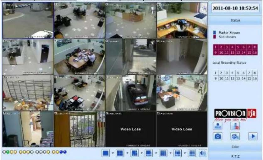
Fig 7-1 View with IE browser
Digital Video Recorder User Manual
7.2 Remote Surveillance through Macintosh with Safari:
Note: the current plug-in version supports only the 32-bit mode, so the safari browser must work on 32-bit mode. This works for Lion OS, with Safari 5.1, though upgrading your computer may cause failure to use Safari.
The Setting steps are as follows:
First: Right click safari icon and select "Show in Finder".
Second: Select Applications→Right click "Safari. App"→Select "Get Info".
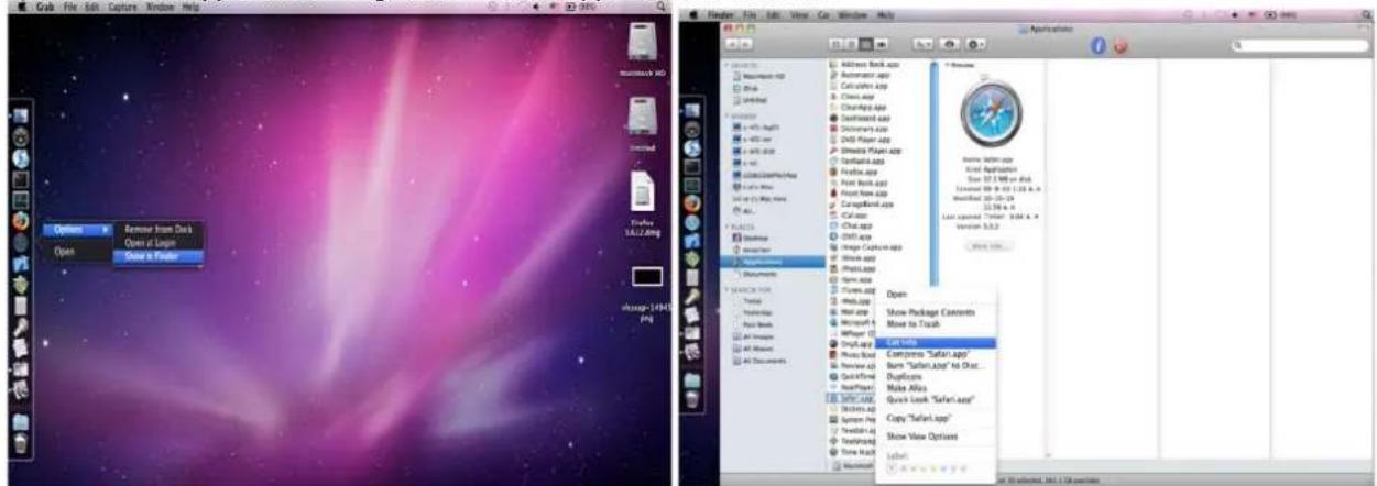
Third: Select "open in 32-bit mode".
Digital Video Recorder User Manual
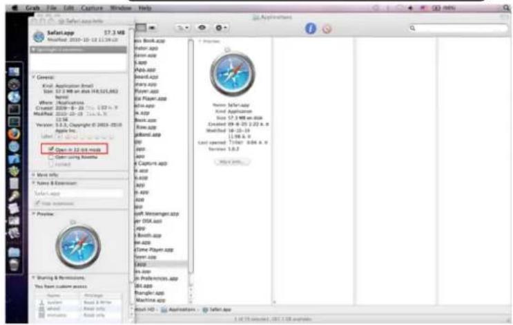
7.2.1 On LAN
Step 1: After starting Apple computer, click Preferences"→"Internet & Wireless"→click "Netv

icon. The following window will pop up. Please select "System
Internet & Wireless


Digital Video Recorder User Manual
Step 2: Enter into Network interface and then click "Ethernet Connected" to check the internet connection of Apple PC.
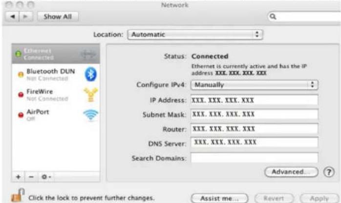
Step 3: After acquiring the IP address, Subnet Mask and so on, please enter into the DVR's Main Menu→Setup→Network interface to manually input IP address, Subnet Mask and Gateway according to the configuration of PC. The network segment should be the same as the PC. If using DHCP, please enable DHCP in the DVR and router.
Step 4: After finishing the above information, users can enter LAN IP and http port in the Safari browser. For example: input http://192.168.1.100:81(here 192.168.1.100 is LAN IP of DVR, 81 is the http port of DVR). Click “” button, the browser will download Active X control as shown below:

Digital Video Recorder User Manual
Step 5: Click icon and then select the Active X control, the welcome interface will be shown. Click "Continue"→"Install" button, the following window will pop up :
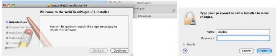
Input the name and password of Apple PC and then click "OK" to install this Active X control.

Step 6: After finishing installing the Active X control, please quit from the Safari browser. Right click icon on the desktop and then select "Quit" button to quit the browser. Then restart Safari browser. Input the IP address and http port to enter into the login interface of DVR.
7.2.2 On WAN
There are also two ways for DVR to connect to Internet.
1. Connect the DVR to internet through router or virtual server
Step 1: The network setups are the same as step one to step four of point 1 on WAN of IE remote surveillance.
Step 2: Enter WAN IP and http port in the Safari browser to install the Active control. The concrete steps are the same as step 5 and 6 of Chapter 7.2.1.
2. Connect the DVR to internet directly.
Step 1: The network setups are the same as step one of point 2 on WAN of IE remote surveillance.
Step 2: Enter WAN IP and http port in the Safari browser to install the Active control. The concrete steps are the same as step 5 and 6 of Chapter 7.2.1.
Digital Video Recorder User Manual
7.3 The remote live preview interface
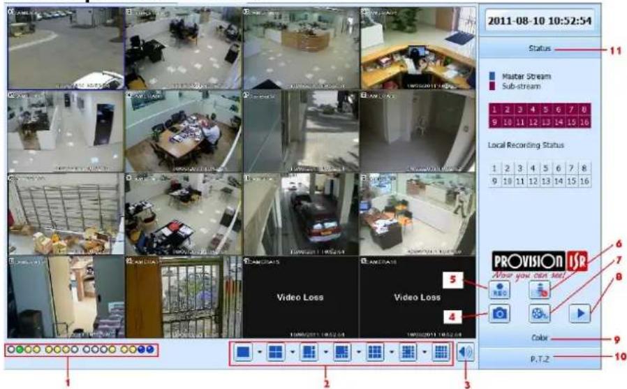
Fig 7-2 Remote live preview interface
Symbol and function Definitions:
| 1 | Channel indicator | 2 | Screen display mode | 3 | Volume |
| 4 | Snapping picture | 5 | Start record | 6 | Two way audio |
| 7 | Start client record | 8 | Playback | 9 | Color menu |
| 10 | PTZ control menu | 11 | Master/sub stream /record status | ||
Digital Video Recorder User Manual
Note: click button to record manual and the record file will be saved in user's PC.
Screen display mode:
Click the ▼ icon beside the screen display mode, channel select dialog will appear as below:
Take 8-channel DVR for example: user can mark channels form 1-ch to 16-ch at random to display the live pictures, 8 channels can be selected at most. Then click OK button to confirm the setting.
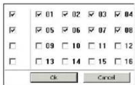
Fig 7-3 Channel select dialog
Snap pictures
Click "Snap" icon, the system will automatically capture pictures and save those pictures in the computer. User should set up the save path for those pictures in the Remote Preview interface Configuration Local configuration.
Color adjustment:
Drag the slide bar to adjust Brightness, Contrast, Hue, and Saturation. Click Default to reset them to original value.
| Buttons | Description |
| Drag the scroll bar to adjust the brightness of channel | |
| Drag the scroll bar to adjust the contrast of channel | |
| Drag the scroll bar to adjust the saturation of channel | |
| Drag the scroll bar to adjust the hue of channel | |
| Click this button to recover the default value of brightness, contrast, saturation and hue. | |
| Save the adjustment |
PTZ control (next page)
Digital Video Recorder User Manual
Please connect speed dome to the device via RS485 firstly, make sure the protocol of the speed dome is supported by the device and set the relative parameters manually. User can control the dome up, down, right, left or stop rotating on ControlCenter, adjust rotation speed, Iris and zoom, focus on the dome, and set the presets, etc.
Buttons definition:
| Buttons | Description |
 | means the dome rotate up.means the dome rotate up left.means the dome rotate up right means the dome rotate down.means the dome rotate left down.means the dome rotate right down.means the dome rotate left.means the dome rotate right.means the dome stop rotating. |
 | Drag the scroll bar to adjust rotating speed of the dome. |
| 'Iris' button. Click + button near 'Iris' button to increase light of the dome. Click button near 'Iris' button to decrease light of the dome. | |
 | 'Zoom' button. Click button near 'Zoom' button to zoom in the locale picture of this camera. Click button near 'Zoom' button to zoom out the locale picture of this camera. |
 | 'Focus' button. Click + button near 'Focus' button to have long focus. Click button near 'Focus' button to have short focus. |
 | Go to the Preset |
 | Select and do auto cruise |
| Track | |
 | Auto scan |
| Wiper button | |
 | Light button |
Digital Video Recorder User Manual
Click the right mouse on the live interface, a pull-down menu will appear as below
Stream: this DVR supports master stream and sub stream. Master stream has higher frame rate, max 25FPS (PAL) /30 FPS (NTSC) for every channel, but it needs higher network bandwidth simultaneously; second stream has low frame rate, max 6FPS (PAL) /7FPS (NTSC) for every channel, it requires low network bandwidth. Therefore, users can select the stream according to their bandwidth.
All to master/sub stream: set all channel to master stream or sub stream.
Enable audio: enable or disenable audio
Full screen: In full screen status, the live preview picture will display with full screen and the tool bar will be hid; double click left mouse or click right mouse to return
Zoom in: Single channel large screen electronic amplification
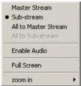
Fig 7-4 right key menu
7.4 Remote playback & backup
7.4.1 Remote playback
Click ▶ button to enter into record playback interface, refer to Fig 7-5:
Select the record date and channels and double-click the file name in the record file list box. Then user can play that file and preview the picture.
Note: the video and sound quality from a remote location could be poor if there is a connectivity problem, in those cases try consulting with a network engineer.
Digital Video Recorder User Manual
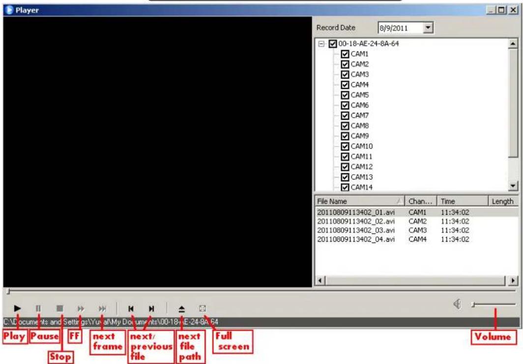
Fig 7-5 Play record file interface
Digital Video Recorder User Manual
This DVR supports remote time search, event search and file management.
By Time Search:
Step1: Enter into Search→time search; refer to Fig 7-6:
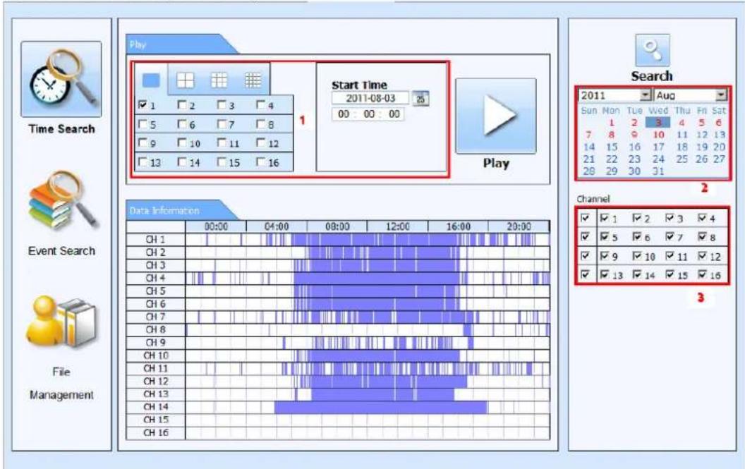
Fig 7-6 time search interface
Digital Video Recorder User Manual
Step2: click "Search" button. The record data will be displayed in the data information list box; the highlight date in the area② means have record data, click those data; select the record channels in area③
Step3: User can set the data playing time and display mode in the area① as required
Step4: Select certain item from the data information list box. Click "play" button to playback
Step5: Click the relevant buttons in the interface and then user can do some operations such as: FF, pause, change channel mode, research, etc. refer to Fig 7-7:
![LIVE SEARCH BACKUP CONFIG TOOLS INFO channel mode Start Time 2011-04-29 00:00:00 play mode play button progress bar the next segment [00:00:00 -- 00:28:59] 2011-04-28 00:00:06 play pause FF FW stop frame full screen volume snap exit](/content/2026/05/1068066/images/ea318fb49de9f044c871a5fb9e1ddd49c1aca7d0debad62168be6da63f0367de.jpg)
Fig 7-7 Time search playback
Digital Video Recorder User Manual
By Event Search:
Step1: Enter into Search→event search; refer to Fig 7-8:
| Event list | |||
| CH | Start time | End time | Type |
| 1 | 2010-01-09 00:01:07 | 2010-01-09 00:02:16 | motion |
| 1 | 2010-01-09 00:03:28 | 2010-01-09 01:24:11 | manual |
| 1 | 2010-01-09 00:08:36 | 2010-01-09 00:09:31 | motion |
| 1 | 2010-01-09 00:10:10 | 2010-01-09 00:10:58 | motion |
| 1 | 2010-01-09 00:11:30 | 2010-01-09 00:12:15 | motion |
| 1 | 2010-01-09 00:14:48 | 2010-01-09 00:15:43 | motion |
| 1 | 2010-01-09 00:15:45 | 2010-01-09 00:17:09 | motion |
| 1 | 2010-01-09 01:24:11 | 2010-01-09 02:46:11 | manual |
| 1 | 2010-01-09 02:46:11 | 2010-01-09 03:19:45 | manual |
| 1 | 2010-01-09 17:39:52 | 2010-01-09 17:57:12 | manual |
| 2 | 2010-01-09 00:01:07 | 2010-01-09 00:01:53 | motion |
| 2 | 2010-01-09 00:02:18 | 2010-01-09 00:03:01 | motion |
| 2 | 2010-01-09 00:03:01 | 2010-01-09 00:04:12 | motion |
| 2 | 2010-01-09 00:03:32 | 2010-01-09 00:54:27 | manual |
| 2 | 2010-01-09 00:14:22 | 2010-01-09 00:15:33 | motion |
| 2 | 201O- - - - - - - - - - - - - - - - - - - - - - - - - - - - - - - - - - - - - - - - - - - - - - - - - - - + | ||
| 2 | 2. OI-OI-OI-OI-OI-OI-OI-OI-OI-OI-OI-OI-OI-OI-OI-OI-OI-OI-OI-OI-OI-OI-OI-OI-OI-OI-OI-OI-OI-OI-OI-OI-OI-OI-OI-OI-OI-OI-OI-OI-OI-OI-OI-OI-OI-OI-OI-OI-OI-OI-OI-SO | ||
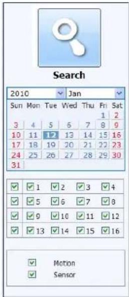
Fig 7-8 event search interface
Step2: click the highlight date and select record channels and then mark the event type: motion and sensor. Then click "search" button
Step3: the events will be display in the event list box and then double-click certain item to playback
Digital Video Recorder User Manual
File Management
Step1: Enter into Search→file management; refer to Fig 7-9:
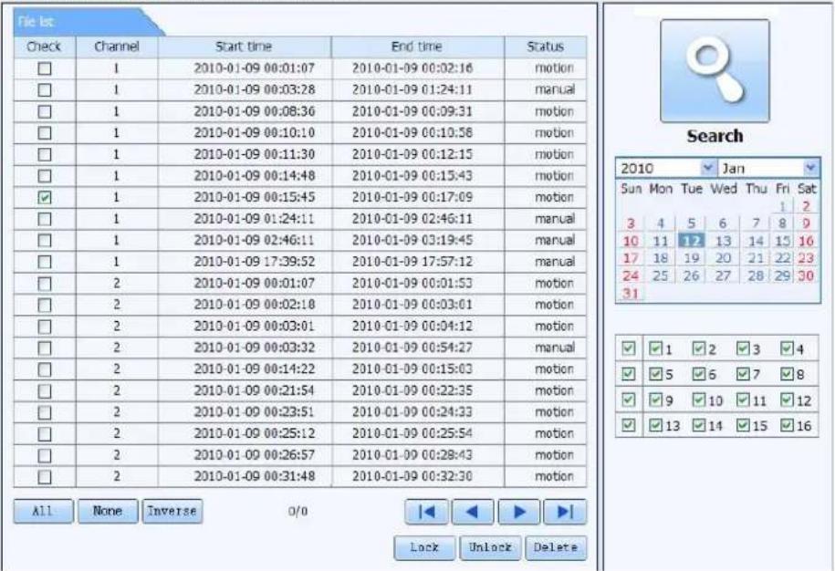
Fig 7-9 file management interface
Lock: select certain file item in the file list box and then click "Lock" button to lock this file that can not be deleted or overlaid
Unlock: select a locked file and then click "unlock" button to unlock this file
Delete: select an unlock file and then click "delete" button to delete this file from file list
Digital Video Recorder User Manual
7.4.2 Remote backup
Click Backup button to enter into backup interface, refers to Fig 7-10:
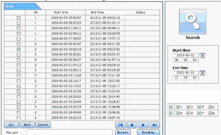
Fig 7-10 remote backup interface
Step1: select channels, set the start and end time and then click "search" button to display the file information in the file list box Step2: select backup files and click "browse" button to set the save path. Then click "backup" button to start backup. The backup files will be saved on user's PC.
Digital Video Recorder User Manual
7.5 Remote System configuration
User can remote setup the parameters of the device. Functions of remote configurations include: basic configuration, live configuration, record configuration, schedule configuration, alarm configuration, network configuration, PTZ configuration and user configuration. User should firstly select an item in the menu list on the left, and then setup the relative parameters. When one user setup parameters of a certain item, others cannot setup this one. Click Config to enter into the below interface refer to Fig 7-11:
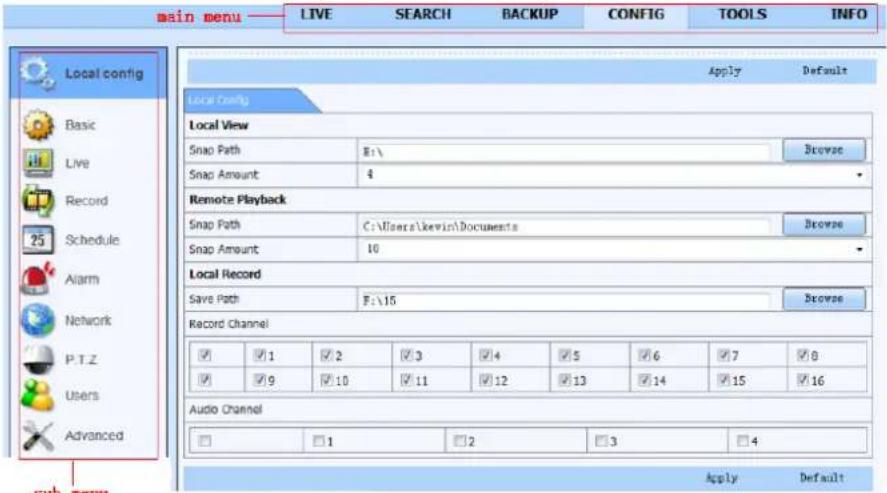
Fig 7-11 remote menu setup
The sub menu lists and the options in every item are similar with those on the DVR. Please refer to Chapter 3 Main Menu Setup Guide for more details.
Click "Apply" button to save above settings; click "default" button will recover the original settings.
Digital Video Recorder User Manual
7.6 Remote Management
Remote Information Search
The system will automatically record the working condition and operation process during the period of work. User can view information, such as username, IP address and so on. Enter into INFO→Log. User can set the start time to view the log record as follows:
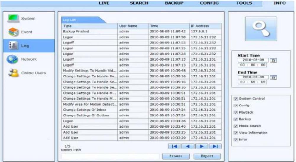
Fig 7-12 Remote information search
Note: There may be subtle differences with respect to functions of remote surveillance from different sources.
Important: Use "Tools" => "Manual Alarm" to activate the manual alarm (and an audible beep from the DVR: shown in chapter 6.2)
Digital Video Recorder User Manual
8 Mobile Surveillance
This DVR supports mobile surveillance by IPhone, Android, blackberry or smart phones with Windows mobile and Symbian OS, though the service may depend on the cellular service provider and 3G network availability and function. Dopod D600 (WM5) and Dopod S1 (WM6) was tested and work fine with the DVR.
To enable mobile surveillance, first enable network service on the DVR and router, please refer to Chapter 4.6 Network configuration. The next chapter is the instructions for mobile clients according to the phones OS.
8.1 iPhone/iPadapp (SuperLivePro for iOS):
- Install from iPhone.
Open App Store in your iPhone (Fig 8.1.1).
Enable "search" function to search "SuperLivePro" (Fig 8.1.2)
Click SuperLivePro, enter into "introduce" interface and then click "FREE", it will change into "INSTALL" (Fig 8.1.3)
Input iTunes Store password and then click "OK", the software will be installed automatically.
Note: if there is no Store account, you must register.
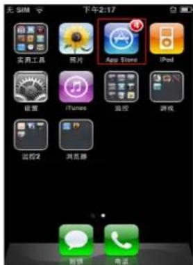
Fig 8.1.3
Digital Video Recorder User Manual
8.2 SuperLivePro 1.0 Manual (for iOS)
Login interface
Input server's IP address (or domain name), user name and password Click "Remember server" to save the setting; click button user can quick input saved server address, user name and password.;
If failed connecting, please check below points;
1.) Check the network connection to your iPad/iPhone.
2.) Check if the server address input is invalid.
3.) Check the username and password, please note that they are case sensitive; Note:do not usespacesin the username or password.
4.) Try changing the DVR's HTTP port and DATA port; in some countries, some ports may be blocked by carriers.
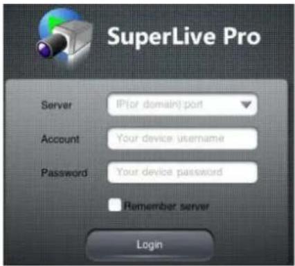
Fig 8.1.4
Live View Interface(Fig. 2)
After the log in, enter the live interface, then tap the proper key for the different function. (main screen, enlarge picture, 2-way audio, color adjustment, PTZ and PTZ presets.
Digital Video Recorder User Manual
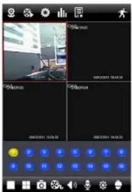
Main screen
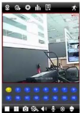
Enlarge picture
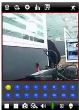
2-way audio
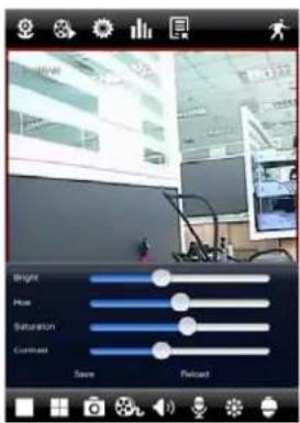
Color adjustment
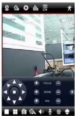
PTZ
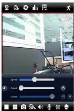
PTZ Presets
Digital Video Recorder User Manual
NavBarIcon meaning:
Quick Launch Bar Instruction:
Gestures instruction :
1.) Tap to select the current channel, double tap the live image to switch to single channel or multi-channel displaying.
2.) Press for 2+ seconds and drag to swap the position of a live channel.
3.) Tap to go back to normal mode when in full screen
Snapshots interface
You can see the captured images in the Image interface (Fig. 8.1.7), tap the thumbnail to check the full image.
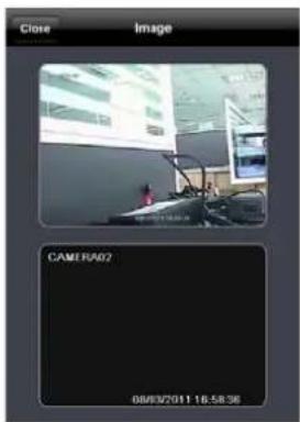
Fig. 8.1.7
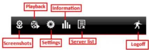
Fig. 8.1.5
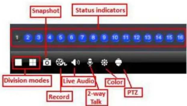
Fig. 8.1.6
Digital Video Recorder User Manual
Using the playback interface you can playback files on the DVR, follow the next steps just like on the web or local interface:
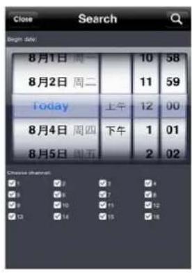
Remote file search
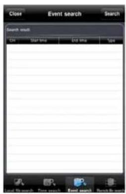
Event search
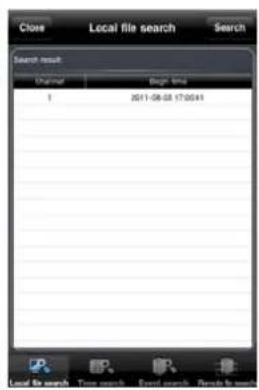
Local file search
Digital Video Recorder User Manual
Configuration and information interface to change DVR settings:
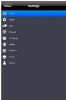
Settings menu
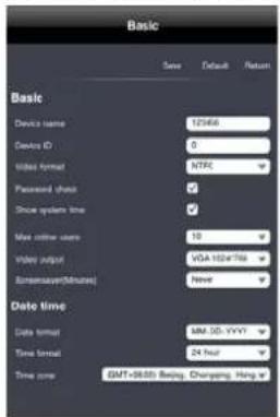
Basic menu
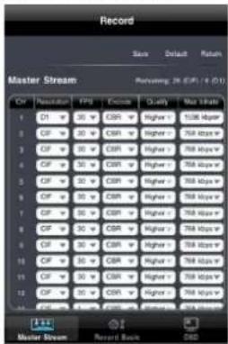
Record menu
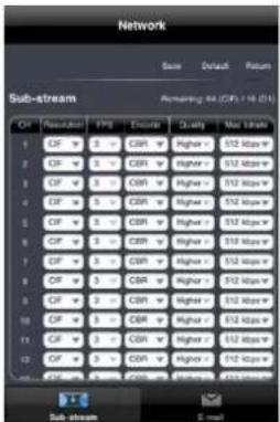
Network menu
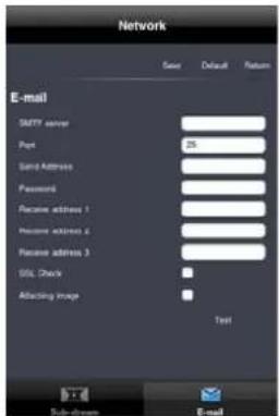
Email menu
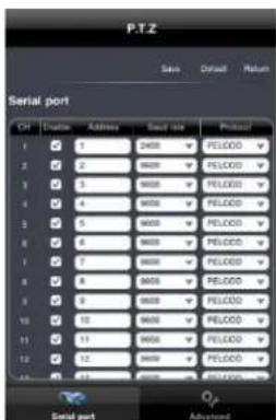
PTZ menu
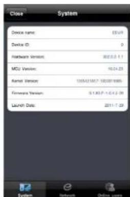
System menu
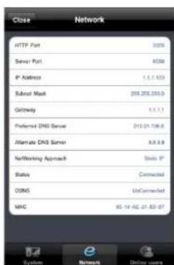
Network menu
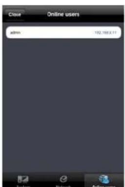
Online users
Digital Video Recorder User Manual
Device list interface for quick login (figure 8.1.8-8.1.9):
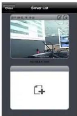
Fig. 8.1.8
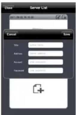
Fig. 8.1.9
Digital Video Recorder User Manual
8.4 Windows Mobile application
Step1: Firstly activate the network access on mobile phone and then run "Internet Explorer". Input the server's address and the connection is built up shown as below picture in the left:
Step2 : Click on the software name. A dialog box pops up as below picture in the middle:
Step3 : Click "Yes" to start downloading and installing:
Step4 : PCam will be opened automatically after installed. Refer picture in the right:
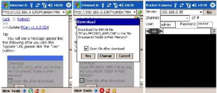
Step5 : Input the server's address, ID and password respectively in the columns of "Server", "User" and "Password", and click "Go" to log on the server. It will show the picture if access successfully. Refer below picture in the left:
Step6 : Camera 1 is the default channel after login. Change the channel in rolling-down menu of "Channel": refer below picture in the right:
Digital Video Recorder User Manual
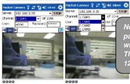
Notice: User name and password here are the same with that used on the DVR. The default is admin and 123456.
8.5 Symbian OS application
Please use the smart phones with symbian version supported by this unit. The detail information is as follows:
| Symbian S40 | support |
| Symbian UIQ | support |
| Symbian S80 | support |
| Symbian S60 | support |
| Symbian S60 3^rd Edition-Symbian OS v9.1 | support |
| Symbian S60 3^rd Edition with FP 1-Symbian OS v9.2 | support |
| Symbian S60 3^rd Edition with FP2-Symbian OS v9.3 | support |
| Symbian S60 5^th Edition-Symbian OS v9.4 | support |
| Symbian S60 5.1 Edition-Symbian OS v9.5 | support |
Step1: Firstly enable the network access on mobile phone. Then run Web browser.
Step2 : Input the DVR server's IP address in a new-built bookmark. Click this bookmark to connect to the DVR.Refer picture in the left:
Digital Video Recorder User Manual
Step3 : A welcome window will pop up and requires a package. Click the software name to download. Refer picture in the right:
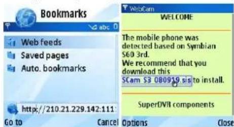
Step4 : A security windows will pop up after downloading and ask if install the package. Click YES to install.
Step5 : A Scam shortcut icon appears on the system menu after finished.
Step6 : Run Scam program. It will enter a function interface. Refer picture in the left:
Step7 : Click System setting-->Login Setting to enter login interface.Refer picture in the right:
Live view: to do mobile live view. Image view: to check the pictures Snapped in live view.
System setting: Login setting And Alarm setting
Help: function indication and help
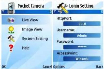
Step8 : Input the server's address, ID and password respectively. Then save.
Notice: About Access point, there may be different access points in different countries or from service providers.
Step9 : Enter Live View, it will connect the server and display pictures. Refer picture in the left:
Digital Video Recorder User Manual
Notice: User name and password here are the same with that used on the DVR. The default is admin and 123456. Step10 : In Live View, users can do snapshot, change channels and control PTZ. Refer picture in the right:
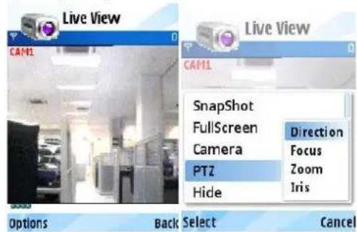
8.6 BlackBerry OS application installation guide
8.6.1 Installation instruction for BlackBerry Mobile phone Client
- Open the browser of BlackBerry phone and enter sever address
- Click "SuperCam" to link
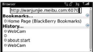
- Click "Download" button on the popup interface and the download progress will be shown.
Digital Video Recorder User Manual
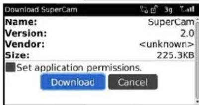
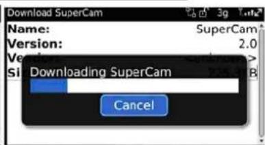
- Finished downloading, the software will be installed automatically.
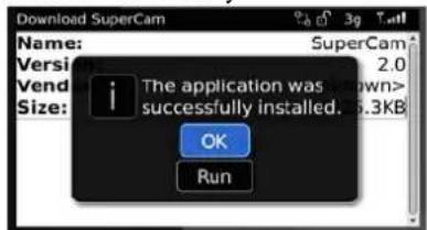
Note: If the software fails to download, please check in accordance with the following steps:
- Check whether the network of mobile phone is normal or not
- Check whether DVR server connect network normally or not
- Modify the option of Browser Configuration.
(1) Enter into Menu->Option->Browser Configuration; configure referring to the following figure in the left.
(2) Enter into Menu->Option->Cache Operations, clear up browser cache. Refer below picture in the right:
Digital Video Recorder User Manual
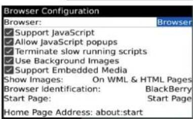
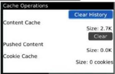
Note : When user used the SuperCam software in mobile phone with touch screen, there will be compatible problem.
Solution: Enter into Options Menu->Advance options->Applications->SuperCam and click "Disable Compatibility" button. This problem will be solved.
8.6.2 BlackBerry OS application guide
1. Login
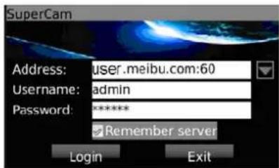
Enter server's IP address (or domain name), user's ID and password.
Click "Remember server" to save the setting; click ▼ button can quick input saved server address, user name and password.
Digital Video Recorder User Manual
2. Main interface
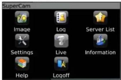
| Playback | playback record file | Image | image view |
| Log | log record | Server List | device list |
| Information | device information view | Help | software help center |
| Logoff | logoff and return to login interface | Settings | software setting |
| Live | live view |
3. Live view
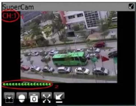
Note: User can click Return button on the Blackberry phone to return the previous interface.
| Mark 1 | Current viewing channel | Mark 2 | Channel status | ||
| [W240] | Switch channels |  | PTZ, click to switch to Fig 2 interface | ||
 | Snap |  | Full screen | ||
 | Background alarm |  | Stop rotating the PTZ | ||
 | Upward rotates the PTZ |  | Downward rotates the PTZ | ||
| [YOKT] | Leftward rotates the PTZ | [OT9C] | Rightward rotates the PTZ | ||
 | Zoom In/Focus In/Iris Add |  | Zoom Out/Focus Out/Iris Sub | ||
| Preset | Select the preset point | Group | Set the cruise line | ||
Digital Video Recorder User Manual
4. Server list
5. Software configuration
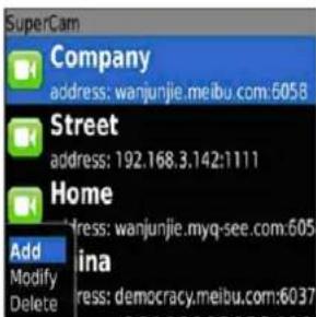
[Add] Add a server list
[Modify] Modify a server list
[Delete] Delete a server list
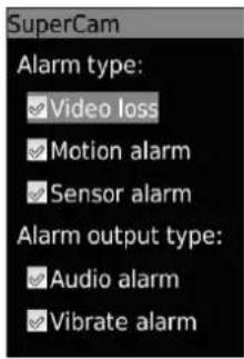
Alarm type: Setup the type of background alarm
(Video Loss/Sensor/Motion)
Alarm output type: Setup prompt type of background
Alarm (sound alarm/ bibrate alarm)
6. Information view
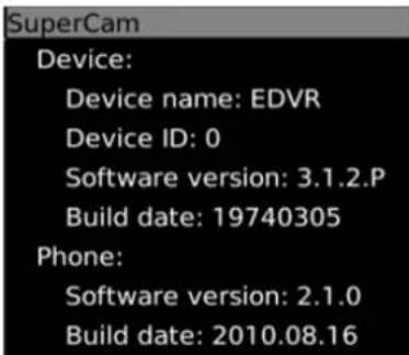
Device ID: the current connection device ID
Software version: the current connection device software version
Build date: the current connection device build date
Software version: the software version of mobile phone in use
Software build date: the software build date of mobile phone in use
Digital Video Recorder User Manual
Appendix A
Q&A
Q1. Why can't the DVR start after connecting to the power?
a. The adapter has been damaged or is malfunctioned, change power adapter.
b. The HDD might be malfunctioning Please remove the HDD to check.
Q2. The menu is missing from the live image display
a. Right click on the attached mouse or click the "menu" button on the DVR or remote.
b. Press the ESC button for 5 seconds until you hear a beep.
Q3. The led power indicator is on, but the screen is black
a. The power of the adapter is malfunctioned; try removing the HDD or change the power adapter.
b. The video format of the DVR is not compatible to that of the monitor.
c. Connection problem. Please check the integrity and placements of all cables and ports of the monitor and DVR.
d. The monitor is malfunctioning, check the monitor.
Q4. Why are there missing images on some or all of the channels of the DVR?
a. Connection problem. Please check the cable and the ports of all camerasto the DVR.
b. Camera problem. Please check the cameras and their power supply.
c. The video format of the DVR is different from that of the cameras. Please change DVR system format.
Q5. Cannot find HDD
a. The power of the adapter is not supplying enough power. Change the adapter.
b. Connection problem. Check the power and data cables.
c. The HDD is damaged. Change the HDD.
Digital Video Recorder User Manual
Q6. Cannot record
a. HDD not formatted. Format it manually to FAT32 first.
b. The record function is disabled or the setup is not correct. Please refer to Chapter 5 Record, search, playback and backup.
c. HDD is full and the recycle function is turned off. Please refer to 4.3 Record configurations. Changethe HDD or enable recycle.
d. The HDD is damaged. Change to a new one.
Q7. The mouse is not working.
a. wait 1-2 minutes after the mouse is connected. Try pressing up/down on the remote control to activate the mouse.
b. mouse not detected. Unplug then plug again.
c. The mouse is incompatible or malfunctioned. Please change the mouse.
Q8. Cannot download ActiveX control.
a. IE browser blocks activeX. Please do setup following below.
① Open IE browser. Click Tools----Internet Options....
Digital Video Recorder User Manual
②select Security----Custom Level....Refer to Fig 8-1
③Enable all the sub options under "ActiveX controls and plug-ins" refer to Fig 8-2
④ Then click ok to finish setup.
b. Other plug-ins or anti-virus block activeX. Please uninstall or close them.
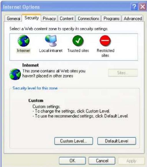
Fig8-1
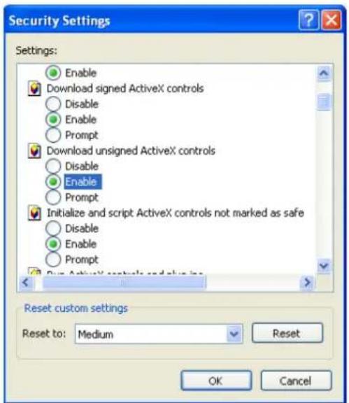
Fig8-2
Digital Video Recorder User Manual
Q9: when DVR starts, it displays "please wait..." all the time
First option: hard-disk data cable is causing the problem.
Solution: shut down and unplug the DVR from the power, check the cables connected to the hard-disk are connected. If this does not solve the problem try using different cables.
The second possible reason: DVR is forced to stop because hard disk has disabled track which causes the system checking hard while the disk cannot skip. Solution: Change another new hard disk or reformat the HDD.
Q10: How to input password and digital numbers
The method to input password and digital numbers is to click the password box, and thenavirtual keyboard will appear. Select the desired character (the initial password is 123456). To add the password, use the digital keys in the front panel or the digital keys on the remote controller.
Q11: Why is the hard disk used in a DVR identified as a new hard disk if directly used to another same type DVR? And why must we format it again?
When DVR only uses one hard disk, the hard disk removed from one to another same type DVR can work normally without format. However, when a DVRadds to a new hard disk, it will identify the hard disk as a new one and inquire whether to format no matter whether this hard disk used or not in another same type DVR before. In this condition, it can be used normally after formatted according to the guide; if two or more hard disks used in different DVRs, when used in another DVR with the same type, they will be identified to be two or more new hard disks, and all of them need to format. In general, please do not try using disks removed from a different DVR because the data may be lost.
Digital Video Recorder User Manual
Q12: Whatare the minimum configurations of PC for clients connecting?
| PC Module | Parameters |
| CPU | Intel Celeron 2.4G |
| Motherboard | Intel 845 |
| HDD | 80G |
| RAM | 512M |
| VGA | NVIDIA GeForce MX440/FX5200ATIRADEON 7500/X300 |
| OS | Windows 2000(SP4 above) /Windows XP(SP2 above) /VISTA |
| DirectX | 9.0 |
Q13: What are the PC configurations for 16-ch real time product with fully open channel mainstream?
| PC Module | Parameters |
| CPU | Intel Core(TM)2 Duo CPU E4600 |
| Motherboard | G31/P31 chip |
| HDD | 80G |
| RAM | 1GB |
| VGA | GMA3100/NVIDIA GeForce 8400/ATIRADEON HD3450 |
| OS | Windows 2000(SP4 above) /Windows XP(SP2 above) VISTA |
| DirectX | 9.0 |
Q14: How to handle the situation when codec Control is blocked to install in the VISTA or Win7 system?
If user gets this problem, may have two ways to fix it:
Digital Video Recorder User Manual
a. Enter Control Panel→User Account and Family Safety → User Account Control(refer to below picture); click Turn User Account on or off. Cancel Use User Account Control (UAC) to help protect your computer.
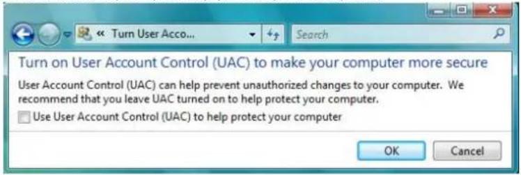
b. Right click IE browser (refer to Fig 14-2), select Run as administrator to run browser.
Digital Video Recorder User Manual
Appendix BCalculate Recording Capacity
Users can calculate the size of hard disk according to the saving time and DVR recording settings. The DVR uses fixed video bit rate. The below are the details at different settings.
| Video Format | Resolution | Frame RateTotally(FPS) | Video Quality | Bit Rate(kbps) | Used Space(MB/h) |
| NTSC CIF | 30 | Highest | 1M | 465 | |
| Higher | 768k | 297 | |||
| Medium | 512k | 230 | |||
| Low | 384k | 173 | |||
| Lower | 256k | 115 | |||
| Lowest | 128k | 56 | |||
| PAL CIF 25 | Highest | 1M | 466 | ||
| Higher | 768k | 295 | |||
| Medium | 512k | 235 | |||
| Low | 384k | 175 | |||
| Lower | 256k | 112 | |||
| Lowest | 128k | 56.4 |
The calculation format is: Total Recording capacity = Usedspace perhour (MB/h) (coverage rate of hard disk) × recording time (hour) × channel numbers (D1 resolution uses 4 times more space then CIF resolution)
For instance, one customer uses PAL cameras, set resolution to CIF, video quality to Lowest, frame rate to 25fps for enabling total 16 channels. He wants the unit to record continuously in a month. Below is the calculation:
Total Recoding capacity =56.4(mb/h) X 24(hours/day) X30(days) X16(channels)= 649728(MB)≈650(GB)
Therefore, customers just install two SATA HDDs with 320GB, it can almost record for one month.
Digital Video Recorder User Manual
Appendix C Compatible Devices
1. Verified & compatible USB drives (Format only to FAT32)
| Brand | Capacity |
| SSK | 512MB, 1G, 2GB |
| Netac | 4GB |
| Kingston | 2GB, 4GB |
| Aigo | 2GB |
| Smatter vider | 1GB |
| SanDisk | 4GB |
2. Verified& compatible SATA CD/DVD writers (only for backup)
| Brand | Model |
| TECLAST | GH22NP20/TL-22XD |
| BENQ | DW220S-0K4 |
| LITEON | DH—20A6S01C |
| LITEON | DH-20A4P02C |
| SAMSUNG | TS-H653B |
Digital Video Recorder User Manual
- Verified & compatible HDD list
| Brand | Capacity |
| WD AV-GP 20EURS-73S48Y0 | 2.0T |
| WD AV-GP 10EURS-630AB1 | 1.0T |
| WD 1002FAEX-00Z3A0 | 1.0T |
| WD AV-GP 5000AVDS-63U7B1 | 500G |
| WD 5000AADS-00L4B1 | 500G |
| WD AV-GP 3200AVVS-63L2B0 | 320G |
| WD 3200AAJS | 320G |
| Seagate Barracuda LP ST2000DL003 | 2.0T |
| Seagate Barracuda LP ST3200542AS | 2TB |
| Seagate Barracuda 7200.11 ST31500341AS | 1.5T |
| Seagate SV35.3 ST31000340SV | 1T |
| Seagate Pipeline HD.2 ST3500312CS | 500G |
| Seagate Barracuda 7200.10 ST3500630AS | 500G |
| Seagate Barracuda 7200.10 ST3250310AS | 250G |
| Seagate Barracuda 7200.10 ST3320620AS | 320G |
| Seagate Barracuda 7200.10 ST3250310AS | 250G |
| HITACHI Deskstar HDT725025VLA380 | 250G |
| HITACHI Deskstar HDT725032VLA360 | 320G |
Digital Video Recorder User Manual
Appendix D 4CH DVR Specifications
| SA-4100HDE+ SA-4100H | DX+ SA-4025SDI SA-4100SDI (1U) | |||
| Form at D1 D1 HD-SDI SDI 1080P | ||||
| Number of Inputs 4 4 4 4 | ||||
| Playback Channels 4 4 4 4 | ||||
| Remote Playback Channels | 4 4 1 1 | |||
| Live Preview While Playback | No | No | No | No |
| Loop | No | No | No | No |
| Image Capture | Yes | Yes | Yes | Yes |
| Output Type | CVBS, VGA, HDMI, Spot | CVBS, VGA, HDMI | CVBS, VGA, HDMI | CVBS, VGA, HDMI |
| Dual Display | YES | YES | Yes | Yes |
| Case | Small 1U | small 1U | 1U | 1U |
| Audio Input(Output) | 4(1) | 2(1) | 4(1) | 4(1) |
| Two Way Audio | Yes | Yes | No | Yes |
| Mic In | No | No | No | Yes |
| Alarm In(out) | 4(1) | No(No) | 4(1) | 4(4) |
| PTZ Control | RS485 | RS485 | RS485 | RS485 |
| Recording CIF | 100/120 FPS (Total) | 100/120 FPS (Total) | No | No |
| Recording Channels CIF | 4ch @ 25/30 FPS | 4ch @ 25/30 FPS | No | No |
| Recording D1 | 100/120 FPS (Total) | 100/120 FPS (Total) | No | No |
| Recording Channels D1 | 4ch @ 25/30 FPS | 4ch @ 25/30 FPS | No | No |
| Recording 1080P | No | No | 25/30 FPS (Total) | 100/120 FPS (Total) |
| Recording Channels 1080P | No | No | 4ch @ 6/7 FPS | 4ch @ 25/30 FPS |
| H.264 Compression | Baseline | Baseline | Advanced | High profile |
| HDD | 1 (3TB each) | 1 (3TB each) | 3 (2TB each) | 2 (3TB each) |
| HDD USB Port (E-SATA) | 1(0) | 1(0) | 1(0) | 1(0) |
| Ethernet | 100Mbps | 100Mbps | 1000 Mbps | 1000 Mbps |
| DVD Burner | No | No | Optional | Optional |
| Master Stream | 25/30fps@CIF | 25/30fps@CIF | 1-6/7 FPS @1080P | 25/30fps 1080P |
| Network Stream | 12/15fps @CIF | 12/15fps @CIF | 1-25/30 FPS @CIF | 25/30fps @CIF |
| IR Remote | Yes | Yes | Yes | Yes |
| IR Extention | Optional | Optional | Optional | Optional |
| Mouse | Yes | Yes | Yes | Yes |
| Power Supply | DC 12V/2A | 12V/2A | DC 12V/4A | 12V 4A |
Digital Video Recorder User Manual
Appendix E
8CH DVRSpecifications
| SA-8200N+ | SA-8200HD+ (1U) | SA-8200D1SDI | SA-8200SDI | SA-8100SDI (1U) | |
| Format | D1 + CIF | D1 | HD-SDI + D1 | SDI 1080P | SDI 1080P |
| Number of Inputs | 4 D1 + 4 CIF | 8 | 4 SDI + 4 D1 | 8 | 8 |
| Playback Channels | 8 | 8 | 4 | 4 | 8 |
| Remote Playback Channels | 4 | 4 | 1 | 1 | 1 |
| Live Preview While Playback | No | Yes | No | No | No |
| Loop | No | No | 4 | No | No |
| Image Capture | Yes | Yes | Yes | Yes | Yes |
| Output Type | CVBS, VGA, HDMI, Spot | CVBS, VGA, HDMI, Spot | CVBS, VGA, HDMI, Spot | CVBS, VGA, HDMI | CVBS, VGA, HDMI |
| Dual Display | Yes | Yes | Yes | Yes | Yes |
| Case | Small 1U | 1U | 2U | 2U | 1U |
| Audio Input | 4 | 4 | 4 | 8 | 4 |
| Audio Output | 1 | 1 | 1 | 1 | 1 |
| Two Way Audio | Yes | Yes | No | Yes | Yes |
| Mic In | No | No | No | Yes | No |
| Alarm In | 8 | 8 | 8 | 8 | 4 |
| Alarm Out | 1 | 1 | 4 | 4CH | 1 |
| PTZ Control | RS485 | RS485 | RS485 X2 | RS485 | RS485 |
| Recording CIF | 200/240 FPS (Total) | 200/240 FPS (Total) | No | No | No |
| Recording Channels CIF | 8ch @ 25/30 FPS | 8ch @ 25/30 FPS | No | No | No |
| Recording D1 | 100/120 FPS (Total) | 200/240 FPS (Total) | 100/120 FPS (Total) | No | No |
| Recording Channels D1 | 4ch@25/30FPS + 4ch@6/7FPS | 8ch @ 25/30 FPS | 4ch @ 25/30 FPS | No | No |
| Recording 1080P | No | No | 100/120 FPS (Total) | 200/240 FPS (Total) | 100/120 FPS (Total) |
| Recording Channels 1080P | No | No | 4ch @ 25/30 FPS | 4ch @ 25/30 FPS | 4ch @12/15 FPS |
| H.264 Compression | Baseline | Advanced | Advanced | High profile | High profile |
| HDD | 1 (3TB) | 2 (2TB) | 4 (2TB) | 8 (3TB) | 2 (3TB) |
| HDD USB Port | 1 | 1 | 1 | 1 | 1 |
| E-SATA | No | No | 2 | 2 | No |
| Ethernet | 100 Mbps | 1000 Mbps | 1000 Mbps | 1000 Mbps | 1000Mbps |
| DVD Burner | No | Optional | Optional | Optional | Optional |
| Master Stream | 1-25/30 FPS @CIF | 1-25/30 FPS @CIF | 1-25/30 FPS @1080P | 1-25/30 FPS @1080P | 12/15Fps@1080P |
| Network Stream | 12/15FPS@CIF | 1-25/30 FPS @CIF | 1-25/30 FPS @CIF | 1-25/30 FPS@CIF | 12/15Fps@CIF |
| IR Remote | Yes | Yes | Yes | Yes | Yes |
| IR Extention | Optional | Optional | Optional | Optional | Optional |
| Mouse | Yes | Yes | Yes | Yes | Yes |
| Power Supply | 12V/2A | DC 12V/4A | 100-240 VAC | 100-240 VAC | DC 12V/4A |
Digital Video Recorder User Manual
Appendix F 16CH DVRSpecifications
| SA-16400N+ SA-16400NE+ SA-16400HD+ (1U) SA-6200SDI SA-16400SDI | |||||
| Format | CIF | D1 + CIF | D1 | SDI 1080P | SDI 1080P |
| Number of Inputs | 16 | 4 D1 + 12 CIF | 16 | 16 | 16 |
| Local Playback Channels | 16 | 16 | 16 | 4 | 4 |
| Remote Playback Channels | 4 | 16 | 4 | 1 | 1 |
| Live Preview While Playback | Yes | No | Yes | No | No |
| Loop | No | No | No | No | No |
| Image Capture | Yes | Yes | Yes | Yes | Yes |
| Output Type | CVBS/VGA/HDMI/Spot | CVBS/VGA/HDMI/Spot | CVBS/VGA/HDMI/Spot | CVBS/VGA/HDMI | CVBS/VGA/HDMI |
| Dual Display | YES | No | Yes | Yes | Yes |
| Case | Small 1U | 1U | 1U | 2U | 2U |
| Audio Input (Output) | 4(1) | 4(1) | 4(1) | 16(1) | 16(1) |
| Two Way Audio | Yes | Yes | Yes | Yes | Yes |
| Mic In | No | No | No | Yes | Yes |
| Alarm In | 16 | 16 | 16 | 16 | 16 |
| Alarm Out | 1 | 1 | 1 | 4 | 4 |
| PTZ Control | RS485 | RS485 X2 | RS485 | RS485 | RS485 |
| Recording CIF | 400/480 FPS (Total) | 400/480 FPS (Total) | 400/480 FPS (Total) | No | No |
| Recording Channels CIF | 16ch @ 25/30 FPS | 16ch @ 25/30 FPS | 16ch @ 25/30 FPS | No | No |
| Recording D1 | 100/120 FPS (Total) | 135/165 FPS (Total) | 400/480 FPS (Total) | No | No |
| Recording Channels D1 | 16ch @ 6/7 FPS | 4ch@25/30FPS + 12ch@6/7FPS | 16ch @ 25/30 FPS | No | No |
| Recording 1080P | No | No | No | 200/240 FPS (Total) | 400/480 FPS (Total) |
| Recording Channels 1080P | No | No | No | 16ch @ 12/15 FPS | 16ch @ 25/30 FPS |
| H.264 Compression | Baseline | Baseline | Advanced | High profile | High Profile |
| HDD | 1 (3TB Max) | 2 (3TB each) | 2 (3TB each) | 8 (3TB each) | 8 (3TB each) |
| HDD USB Port (E-SATA) | 1(0) | 1(0) | 1(0) | 1(2) | 1(2) |
| Ethernet | 100M | 1000 Mbps | 1000 Mbps | 1000Mbps | 1000Mbps |
| DVD Burner | No | Optional | Optional | Optional | Optional |
| Master Stream | 1-25/30 FPS @CIF | 1-25/30 FPS @CIF | 1-25/30 FPS @CIF | 12/15fps@1080P | 1-25/30 FPS @1080P |
| Network Stream | 12/15Fps@CIF | 1-6/7 FPS@CIF | 1-25/30 FPS @CIF | 12/15Fps@CIF | 1-25/30 FPS @CIF |
| IR Remote/Extension socket | Yes | Yes | Yes | Yes | Yes |
| Mouse | Yes | Yes | Yes | Yes | Yes |
| Power Supply | 12V/2A | DC 12V/4A | DC 12V/4A | 220V | 220V |
Digital Video Recorder User Manual
Appendix G 24CH/32CH DVRSpecifications
| SA-24600 SA-32800 | ||
| Form at CIF D1* + CIF | ||
| Number of Inputs 24 4 D1* + 28 CIF | ||
| Local Playback Channels 16 16 | ||
| Remote Playback Channels 4 16 | ||
| Live Preview While Playback | Yes | No |
| Loop | No | 32 |
| Image Capture | Yes | Yes |
| Output Type CVBS/VGA/HDMI | CVBS/VGA/HDMI/Spot | |
| Dual Display | No No | |
| Case | 1U | 2U |
| Audio Input | 4 16 | |
| Audio Output | 1 | 1 |
| Two Way Audio | Yes | Yes |
| Mic In | No | 1 |
| Alarm In | 16 16 | |
| Alarm Out | 1 | 4 |
| PTZ Control RS485 X2 RS485 X2 | ||
| Recording CIF | 600/720 FPS (Total) | 800/960 FPS (Total) |
| Recording Channels CIF | No | 32ch @ 25/30 FPS |
| Recording D1 | No | 260/310 FPS (Total) |
| Recording Channels D1 | No | 4ch@25/30FPS + 28ch@6/7FPS |
| Recording 1080P | No | No |
| H.264 Compression | Baseline Baseline | |
| HDD | 3 (2TB each) | 8 (2TB each) |
| HDD USB Port (E-SATA) | 1(0) | 1(2) |
| Ethernet | 1000 Mbps | 1000 Mbps |
| DVD Burner | Optional | Optional |
| Master Stream | 1-25/30 FPS @CIF | 1-25/30 FPS @CIF |
| Network Stream | 1-6/7 FPS@CIF | 1-6/7 FPS@CIF |
| IR Remote/Extension socket | Yes | Yes |
| Mouse | Yes | Yes |
| Power Supply | DC 12V/5A | 100-240 VAC |