HNW300APN2 - Router Hamlet - Free user manual and instructions
Find the device manual for free HNW300APN2 Hamlet in PDF.


| Product Type | Wireless Router |
| Brand | Hamlet |
| Model | HNW300APN2 |
| Wireless Standard | IEEE 802.11b/g/n |
| Frequency Band | 2.4 GHz only |
| Maximum Data Rate | 300 Mbps |
| Antennas | 2 fixed external omni-directional (2T2R) |
| WAN Port | 1× 10/100 Mbps RJ-45 |
| LAN Ports | 4× 10/100 Mbps RJ-45 |
| Power Supply | DC 12V, 1A (external adapter) |
| Dimensions (W×D×H) | 155 × 115 × 30 mm |
| Weight | 190 g (without accessories) |
| Operating Temperature | 0 °C to 40 °C |
| Security | WEP, WPA/WPA2-PSK, WPA2-Enterprise, MAC address filtering |
| LED Indicators | Power, WAN, LAN (1-4), WiFi, WPS |
| Setup | Web-based configuration interface, Quick Setup Wizard |
| Warranty | 2 years |
Frequently Asked Questions - HNW300APN2 Hamlet
User questions about HNW300APN2 Hamlet
0 question about this device. Answer the ones you know or ask your own.
Ask a new question about this device
Download the instructions for your Router in PDF format for free! Find your manual HNW300APN2 - Hamlet and take your electronic device back in hand. On this page are published all the documents necessary for the use of your device. HNW300APN2 by Hamlet.
USER MANUAL HNW300APN2 Hamlet
User Manual
HNW300APN2
www.hamletcom.com
INDEX
1. Introduction......6
1.1 System Requirements....6
1.2 Package Contents....6
2. Specification....7
2.1 LED Meaning....7
2.2 Connectors 8
3. Installation & Setup....9
3.1 Connection of Wi-Fi Router 9
4. Configuration Procedures....10
4.1 Windows 98SE/ME/2000/XP....10
4.2 Windows Vista.... 12
4.3 Windows 7 15
4.4 Windows 8....17
5. Wi-Fi Router Configuration....21
6. Connect Wirelessly 26
7. Web Configuration ...... 28
7.1 Accessing the Web Interface....28
8. Quick Setup....29
8.1 Operation Mode Setup 30
8.2 WAN Interface Setup.... 32
8.3 Wireless Basic Setup 37
8.4 Wireless Security Setup 44
9. Operation Mode....56
9.1 Setting Operation Mode 56
10. Wireless Network 57
10.1 Basic Settings....57
10.2 Advanced Settings 59
10.3 Security 60
10.4 Access Control 66
10.5 WDS settings....69
10.6 Site Survey 78
10.7 WPS 84
10.8 Operations of AP - AP being an enrollee.... 88
10.9 Operations of AP - AP being a registrar 96
10.10 Wireless Schedule 102
11. LAN Interface.... 103
11.1 LAN Interface Setup 103
11.2 Changing the LAN IP address and subnet mask 105
11.3 Show Client 108
12. WAN Interface.... 109
12.1 Configuring Static IP connection....112
12.2 Configuring DHCP Client connection....113
12.3 Configuring PPPoE connection....114
12.4 Configuring PPTP connection 115
12.5 Configuring L2TP connection....116
12.6 Clone MAC Address....117
13. Port Filtering.... 118
13.1 Port filtering for TCP port 80....119
13.2 Port filtering for UDP port 53 120
14. IP Filtering.... 121
14.1 IP filtering for TCP with specified IP 122
14.2 IP filtering for UDP with specified IP 123
14.3 IP filtering for both TCP and UDP with specified IP 124
15. MAC Filtering.... 125
15.1 MAC filtering for specified MAC Address 126
16. Port Forwarding 127
16.1 Port Forwarding for TCP with specified IP 128
16.2 Port Forwarding for UDP with specified IP 129
17. URL Filtering.... 130
17.1 URL filtering for specified URL Address 131
18. DMZ 132
18.1 DMZ Host IP Address 133
19. VLAN 134
20. QoS 135
21. Route Setup.... 136
22. Status.... 137
23. Statistics.... 138
24. Dynamic DNS.... 139
24.1 Configure DynDNS.... 141
24.2 Configure TZO....142
25. Time Zone Setting 143
SNTP Server and SNTP Client Configuration settings 143
26. Denial-of-Service.... 144
27. Log 146
System Log 146
30.1 Setting your username and password.... 154
31. Logout.... 156
A Configuring your Computers....157
Configuring Ethernet PCs 157
B IP Addresses, Network Masks, and Subnets 158
IP Addresses 158
Subnet masks.... 159
C UPnP Control Point Software on Windows XP 160
UPnP Control Point Software on Windows XP with Firewall 160
D Troubleshooting 163
Troubleshooting Suggestions....163
Diagnosing Problem using IP Utilities 164
E Glossary 166
Dear Customer,
thanks for choosing an Hamlet product. Please carefully follow the instructions for its use and maintenance and, once this item has run its life span, we kindly ask You to dispose of it in an environmentally friendly way, by putting it in the separate bins for electrical/electronic waste, or to bring it back to your retailer who will collect it for free.
Responsibility Statement
The European importer declares that this product is compliant with CE standards. Importer references and contact details available on www.hamletcom.com in the “About Us” section.
The importer for Italy is:
In order to reduce paper consumption we only printed a concise version of CE declaration of conformity and Quick installation guide.
Full compliance declaration and product documentation will be available contacting us at info@hamletcom.com specifying product code and documentation required.
We inform You this product is manufactured with materials and components in compliance with RoHS
Directive 2002/95/CE; with WEEE Directive 2002/96/CE, 2003/108/CE Italian Legislative Decree
2005/151, LVD Directive 2006/95/EC and R&TTE 1999/5/EC for the following standards:
EN 60950-1: 2006 + A11: 2009 + A1: 2010 + A12: 2011
EN 300 328 V1.7.1 2006
EN 300 386 V1.6.1 09-2012
EN 301 489-1 V1.9.2 09-2011
This is a Class B product. In a domestic environment, this product may cause radio interference, in which case the user may be required to take adequate measures.

Trademarks
All trademarks and company names mentioned in this manual are used for description purpose only and remain property of their respective owners.
Changes
The material in this document is for information only and subject to change without notice. While reasonable efforts have been made in the preparation of this document to assure its accuracy, Hamlet assumes no liability resulting from errors or omissions in this document, or from the use of the information contained herein. Hamlet reserves the right to make changes or revisions in the product design or the product manual without reservation and without obligation to notify any person of such revisions and changes.
1. Introduction
The Hamlet HNW300APN2 is a 300Mbit Wi-Fi AP Router based on IEEE 802.11n Wi-Fi standard with a built in 4-port fast Ethernet Switch. It offers the easiest way to share and extend your high-speed DSL/Cable Modem Internet connection, either with or without wires. Network Address Translation (NAT) and VPN pass-through provide your network protection from hackers, while WEP and WPA encryption guard your wireless network for maximum privacy.
1.1 System Requirements
- A computer with pre-installed Ethernet adapter
- Pentium 200MHz processor or above
- Windows 98SE, ME, 2000, XP, Vista, 7 and 8 (for CD setup utility)
- 64MB of RAM or above
- 25MB free disk space
1.2 Package Contents
- Wi-Fi Router 300
• CD-ROM (Software & Manual) - Quick Installation Guide
- Ethernet Cable (RJ-45)
- Power Adaptor
2. Specification
2.1 LED Meaning
The Wi-Fi Router has indicator lights on the front side. Please see below for an explanation of the function of each indicator light.

Power indicator

WPS Active indicator

WAN Active indicator

Ethernet Active indicator

Wireless Active indicator
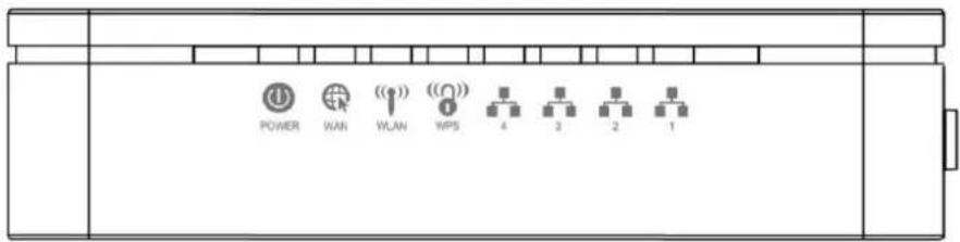
Table 1. LED function
| Label | Color | On | Flash | Off |
 | Green | Ready | Waiting for device ready | Power Off |
 | Green | The device has a WAN IP address from xDSL/Cable Modem | Transmit / Receive Data | No WAN IP address from xDSL/Cable Modem |
 | Green | WLAN Ready | Transmit / Receive Data | WLAN Off |
 | Green | - | Start WPS peer within 2 minutes | WPS Idle |
 | Green | Ethernet Connected | Transmit / Receive Data | Ethernet Disconnected |
2.2 Connectors
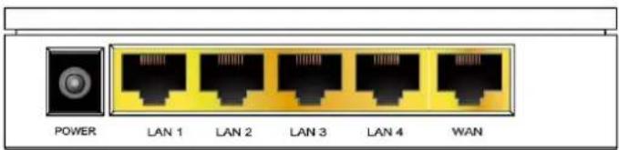
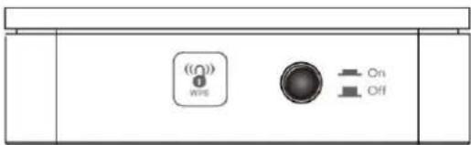
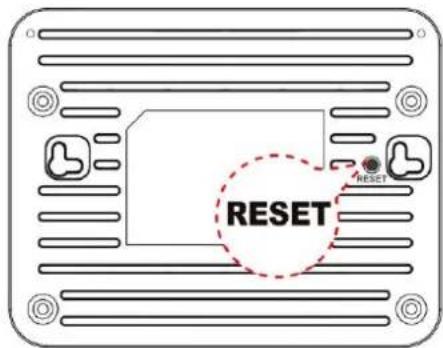
The below table shows the function of each connector and switch of the device.
| CONNECTOR | DESCRIPTION |
| POWER | Connects to the supplied power cable |
| LAN 1/2/3/4 | Connects the device via Ethernet to up to four PCs on your LAN |
| WAN | Connects the device via Ethernet to xDSL / Cable Modem |
| WPS | Press this button for at least three full seconds and the WPS LED will flash to start WPS |
| ON/OFF SWITCH | Power on/off the device |
| RESET | Press this button to reset the Wi-Fi Router to its default factory settings. |
Rear View of the Wireless AP Router
Side view with WPS button and ON/OFF switch
Bottom view with RESET button
3. Installation & Setup
Follow each step carefully and only go to the next step once you have completed the previous one.
Note: Be sure that you are well insulated from any power source to avoid electricity shock.
Note: Use only the manufacturer-approved power supply that shipped with the Wi-Fi Router.
- Connect the power to the Wi-Fi Router by plugging the power supply into an appropriate electrical outlet.
- If the Power LED is off, refer to "Troubleshooting" for information.
3.1 Connection of Wi-Fi Router
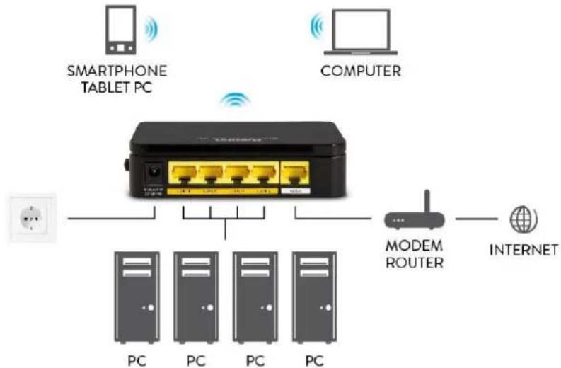
flowchart
graph TD
    A["SMARTPHONE TABLET PC"] -->|Wireless| B["Switch"]
    C["COMPUTER"] -->|Wireless| B
    D["Internet"] -->|Wireless| B
    B --> E["MODEM ROUTER"]
    E --> F["PC"]
    E --> G["PC"]
    E --> H["PC"]
    E --> I["PC"]
- Connect the RJ45 Ethernet cable from your xDSL/Cable Modem's Ethernet port to Wi-Fi Router's WAN Port.
- Connect the supplied RJ45 Ethernet cable from your PC's Ethernet port to any of the four Wi-Fi Router's LAN Ports.
- Connect the power adapter to the power inlet "Power" of the Wi-Fi Router and turn the "ON/OFF" power switch of your Wi-Fi Router ON.
4. Configuration Procedures
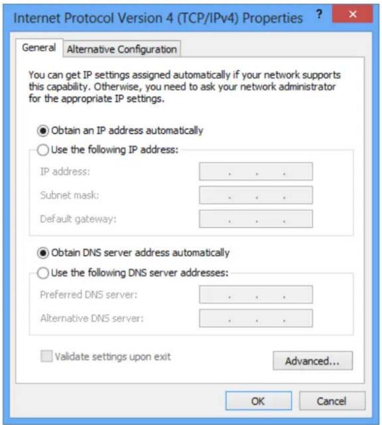
Before starting the Wi-Fi Router configuration, please kindly configure the PC computer as below, to have automatic IP address / DNS Server.
4.1 Windows 98SE/ME/2000/XP
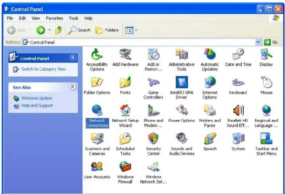
- Click on "Start" > "Control Panel" (in Classic View). In the Control Panel; double click on "Network Connections" to continue.
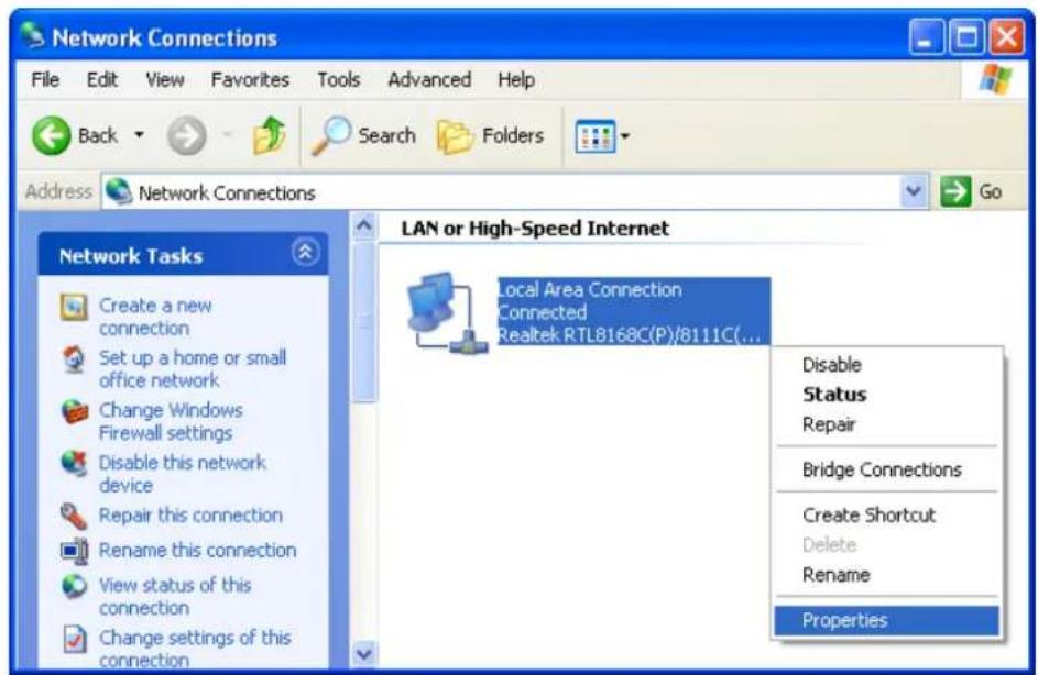
- Right click on "Local Area connection", then click "Properties".
- Double click on "Internet Protocol (TCP/IP)".
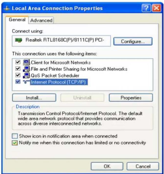
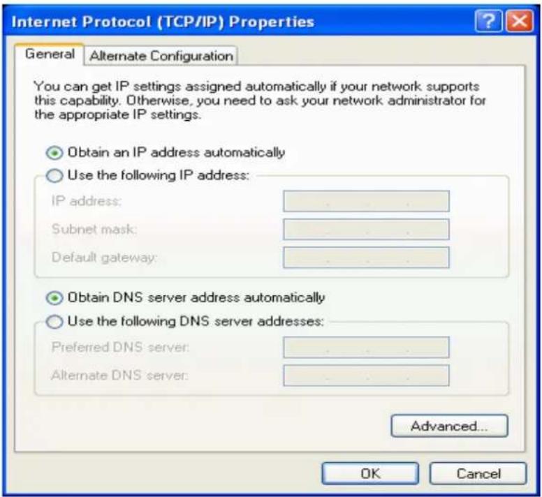
- Check "Obtain an IP address automatically" and "Obtain DNS server address automatically" then click on "OK" to continue.
- Click "Show icon in notification area when connected" (see screen image in 3. above) then click on "OK" to complete the setup procedures.
4.2 Windows Vista
- Click on "Start" > "Control Panel" > "Network and Sharing Center".
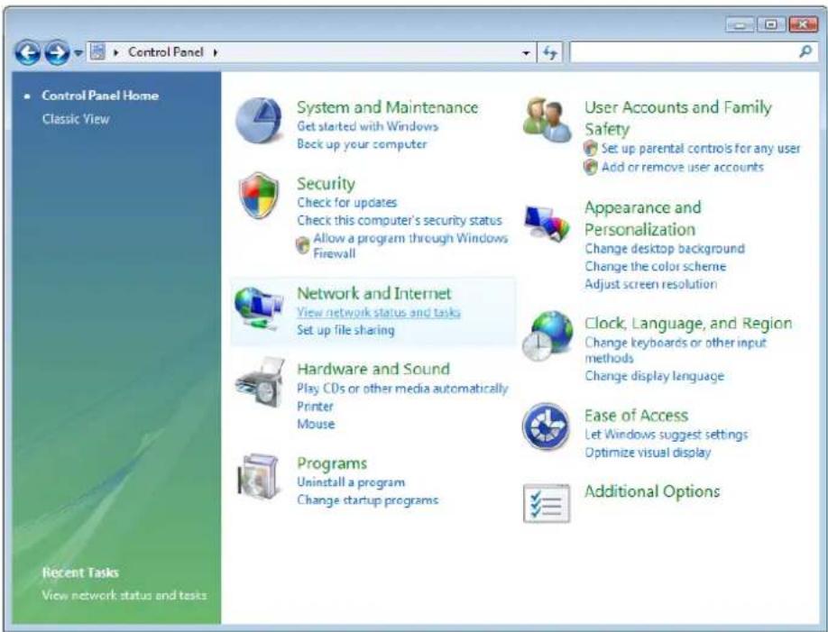
- In the Manage network connections, click on "Manage network connections" to continue.
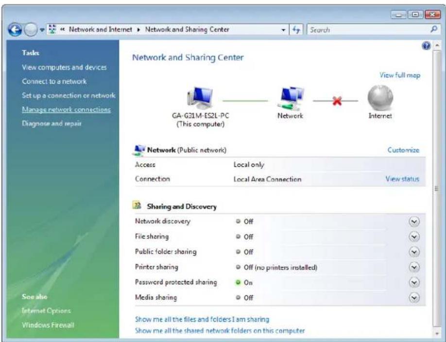
- Right click on "Local Area connection", then click "Properties".
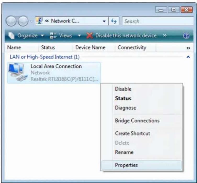
- The screen will display the information "User Account Control" and click "Continue" to continue.
- Double click on "Internet Protocol Version 4 (TCP/IPv4)".
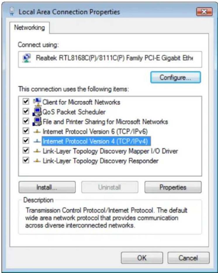
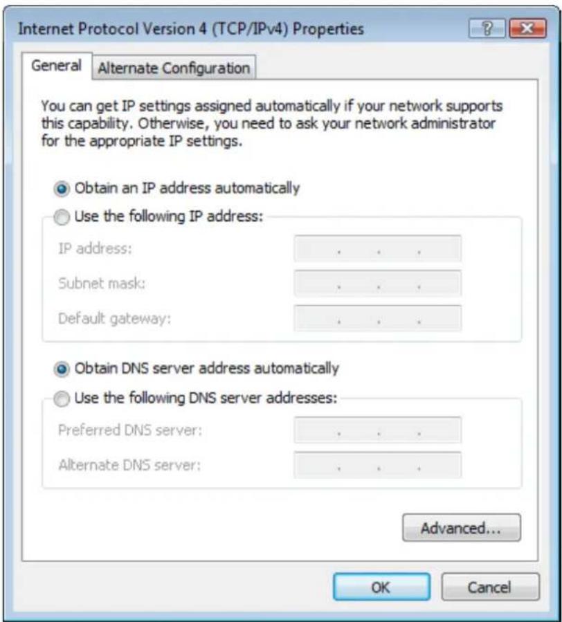
- Check "Obtain an IP address automatically" and "Obtain DNS server address automatically" then click on "OK" to continue.
4.3 Windows 7
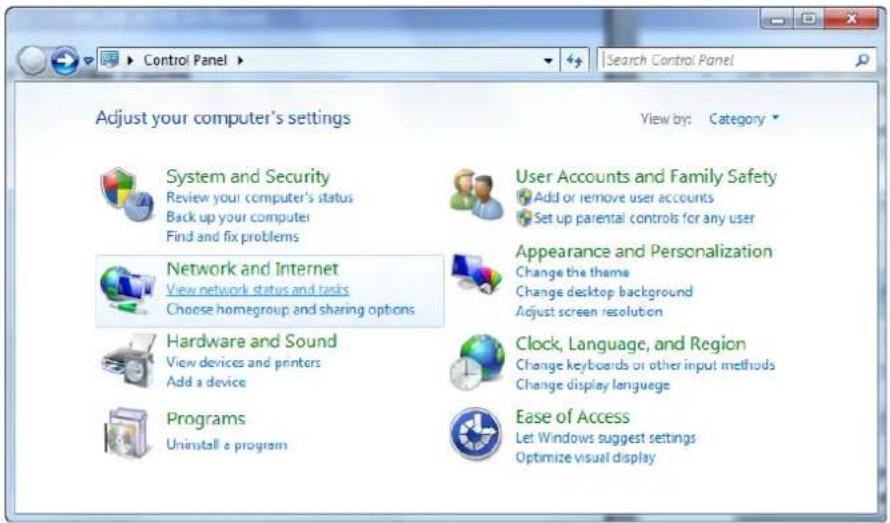
- Click on "Start" > "Control Panel" (in Category View) > "View network status and tasks".
- In the Control Panel Home, click on "Change adapter settings" to continue.
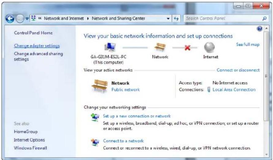
- Right click on "Local Area Connection", then click "Properties".
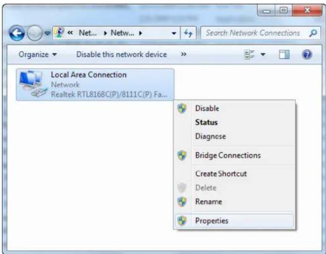
- Double click on "Internet Protocol Version 4 (TCP/IPv4)".
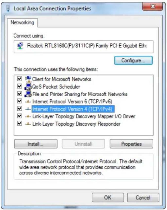
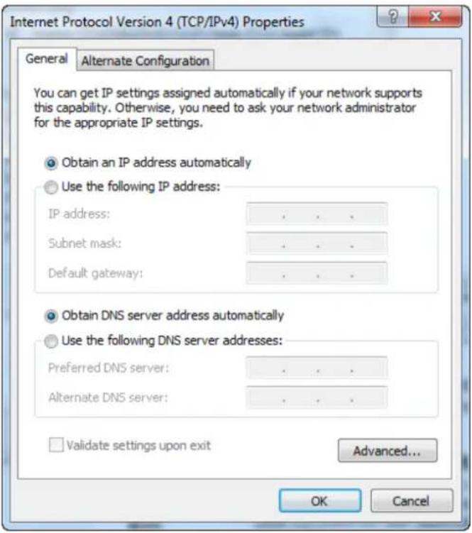
- Check "Obtain an IP address automatically" and "Obtain DNS server address automatically" then click on "OK" to continue.
4.4 Windows 8
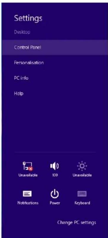
- Move the mouse or tap to the upper right corner and click on "Settings".

- Click on "Control Panel".
3. Click on "View network status and tasks".
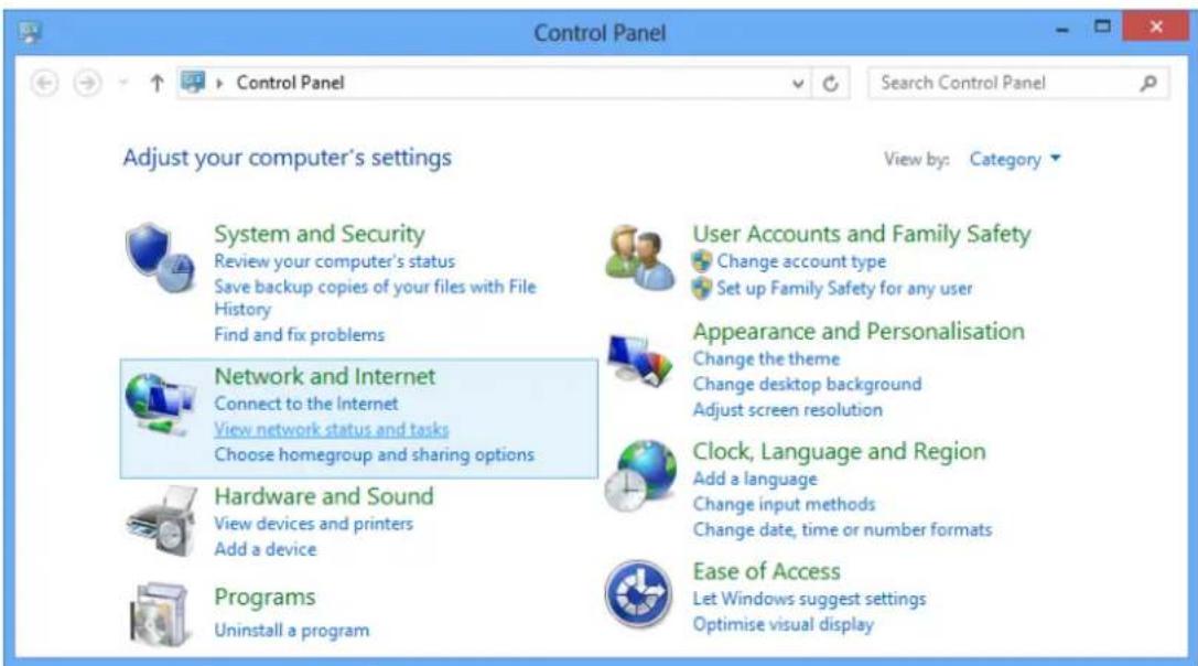
4. In the Control Panel Home, click on "Change adapter settings" to continue.
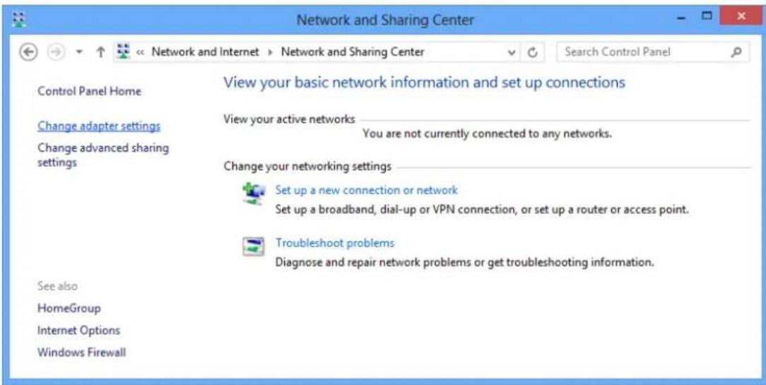
- Right click on "Ethernet", then click "Properties".
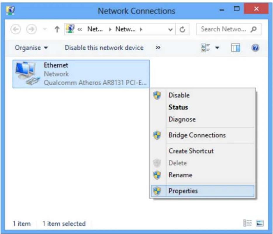
- Double click on "Internet Protocol Version 4 (TCP/IPv4)".
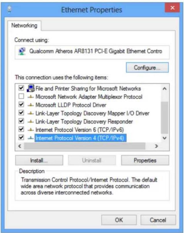
- Check "Obtain an IP address automatically" and "Obtain DNS server address automatically" then click on "OK" to continue.
5. Wi-Fi Router Configuration
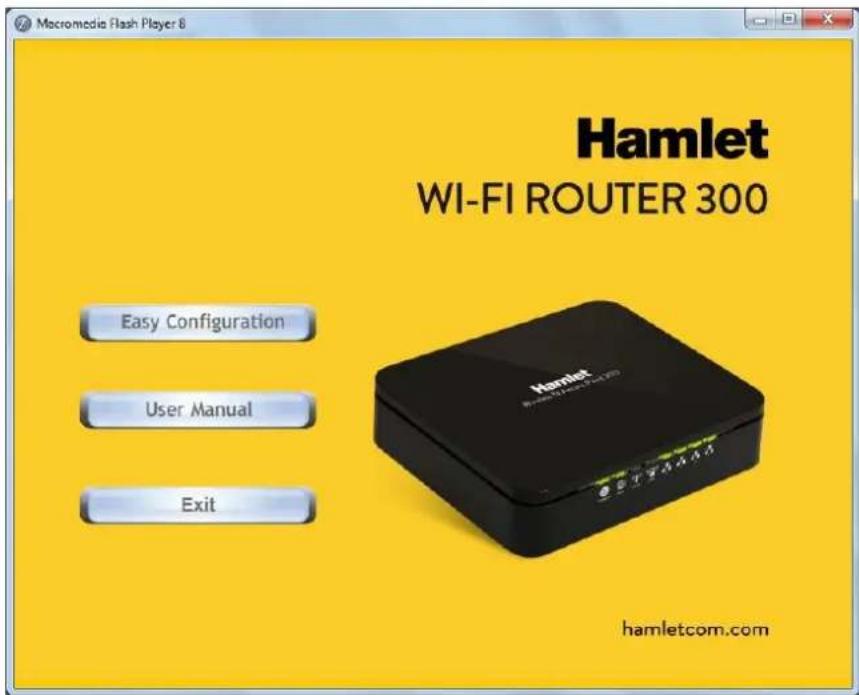
- Please insert the supplied CD into your CD-ROM drive.
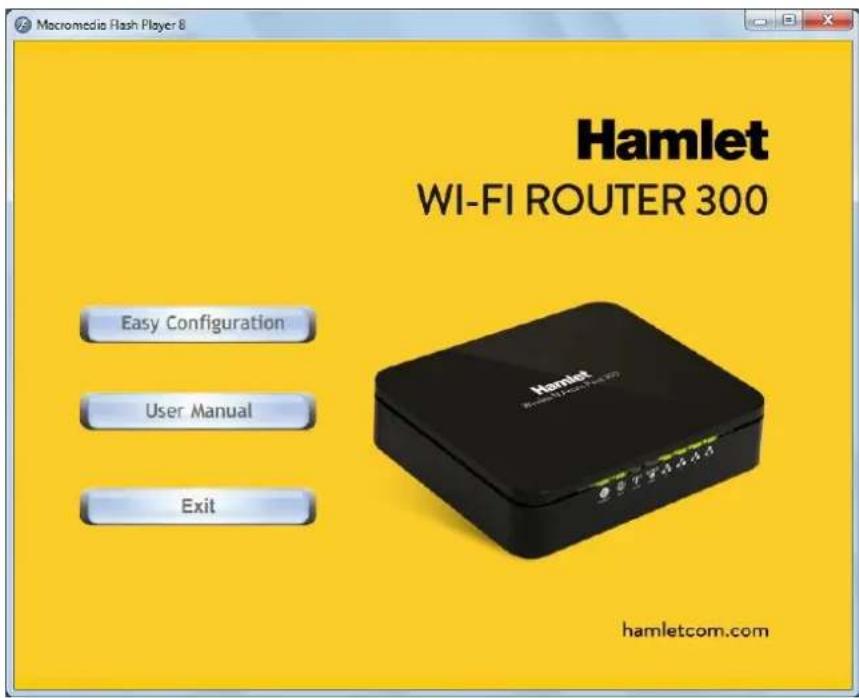
- The CD should auto-start, displaying the window shown in 3 below. If your CD does not start automatically, go to Windows Explorer, Select your CD drive and double click "autorun.exe".
- The screen below will appear. To configure the device, please click "Easy Configuration" button and follow the steps illustrated in the following pages.
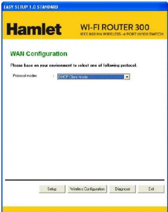
- Select the Protocol mode Fixed IP, DHCP client or PPPoE Mode and enter related parameters that your ISP (Internet Services Provider) or Network Administrator provided and then click "Wireless Configuration".
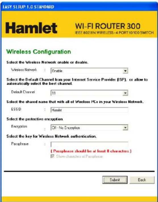
- Please enter the "ESSID" if you want to change the default settings (Network= Enable, ESSID = Hamlet).
- Choose the Encryption type if necessary, as Off – No Encryption (Default) / 64 Bit Encryption / 128 Bit Encryption / Wi-Fi Protected Access (TKIP) / Wi-Fi Protected Access2 (AES-CCMP) and WPA Mixed Mode. For example, you choose the WPA Mixed Mode type and configure Passphrase.
- Please click "Submit" button to continue.
Configuration examples
7-1. PPPoE
Select PPPoE Mode from Protocol modes drop-down list Enter Username and Password offered by the ISP. Click on Setup button
![EASY SETUP 1.0 STANDARD Hamlet WI-FI ROUTER 300 IEEE 802.1IN WIRELESS-4 PORT 10/10 SWITCH WAN Configuration Please base on your environment to select one of following protocol. Protocol modes : PPPoE Mode Please enter your ADSL Username and Password. The information from your Internet Service Provider. [ISP] Username : [Name your ISP gave you ] Password : [Password your ISP gave you ] Show characters of Password Setup Wireless Configuration Diagnose Exit](/content/2026/05/1067938/images/1986da5281a8cf9b091b2bfee6e5d96f2f46cb7b73f616bd1716f1c9911f22f3.jpg)
7-2. DHCP
Select DHCP Client Mode from Protocol modes drop-down list. Click on Setup button
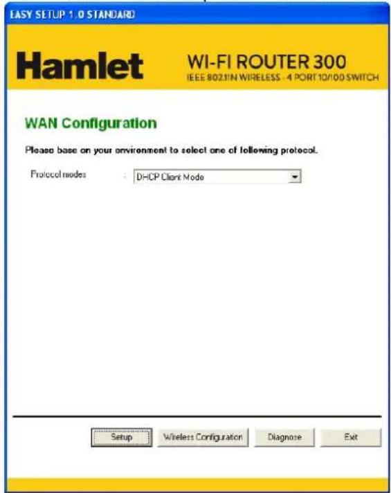
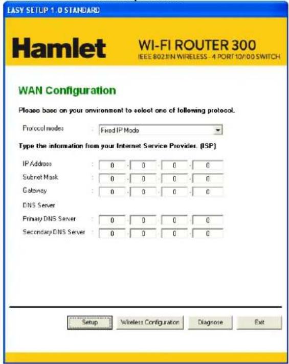
7-3. Fixed IP
Select Fixed IP Mode from Protocol modes drop-down list.
Config IP Address, Subnet mask, Gateway and DNS Server offered by ISP (Internet Services
Provider) or Network Administrator. Click on Setup button
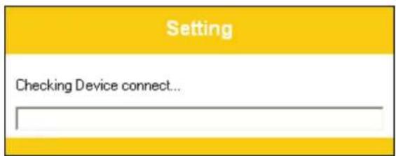
- Now, checking Wi-Fi Router hardware connection, Internet settings, WLAN settings, and connection status.
- Easy setup configuration completed. Click on "Close" to exit this program.
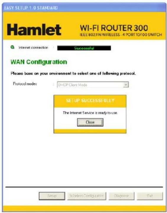
- Click on "Exit" to exit this program.
- Now, the Wi-Fi Router has been configured completely, and suitable for Wireless and Internet Connections.
6. Connect Wirelessly
Now that the Easy configuration setup is completed, you can connect wirelessly to your Wi-Fi AP Router. Follow the steps below to create a new wireless connection.
- Double click on the wireless icon on your computer and search for the wireless network that you enter ESSID name.
![[p] Wireless networks detected One or more wireless networks are in range of this computer. To see the list and connect, click this message](/content/2026/05/1067938/images/b6d41eb4f0d4859bfae222dc93eb4d2d138115994359e14d4d6d45fe17b7b6e7.jpg)
- Click on the wireless network that you enter ESSID name to connect.
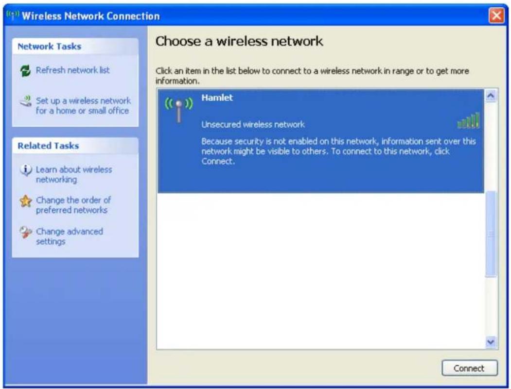
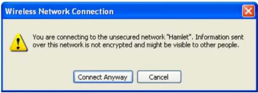
- If the wireless network isn't encrypted, click on "Connect Anyway" to connect.
- If the wireless network is encrypted, enter the network key that belongs to your Encryption type and Passphrase. You can later change this network key via the wireless configuration menu.
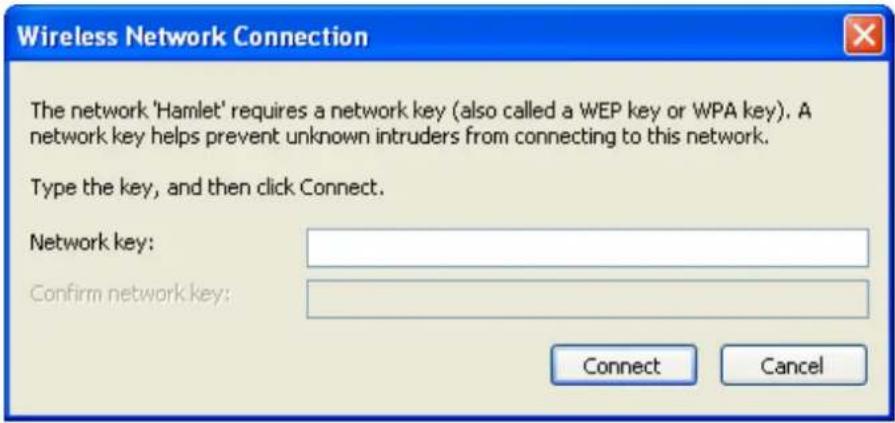
- Click on "Connect" or "Apply".
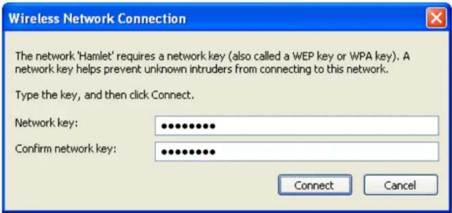
Now, your wireless connection to the Wi-Fi Router has been configured and you are able to connect to ISP / Website.
7. Web Configuration
The embedded web configuration allows you to manage the Wi-Fi Router from anywhere through a common web browser such as Internet Explorer or Firefox. Please note that JavaScript must be enabled.
7.1 Accessing the Web Interface
- Make sure your Wi-Fi Routers properly connected.
- Prepare your computer/computer network to connect to the Wi-Fi Router.
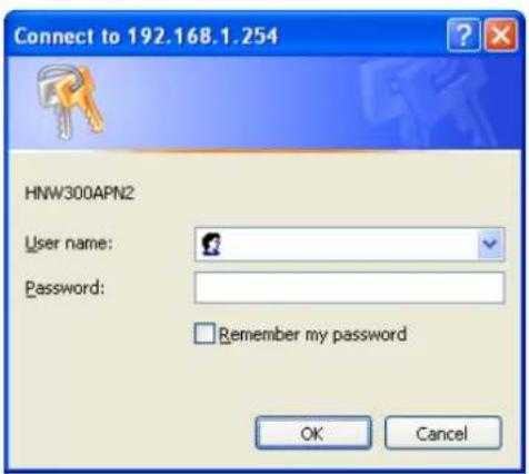
- Launch your web browser and type "http://192.168.1.254" in the address bar.
- An Enter Network Password window displays. Enter the user name ("admin" is the default), password ("hamlet" is the default) and click OK.
- You should now see the Status page of the Router.
Status
This page shows the current status and some basic settings of the device.
| System | |
| Uptime | 0day:0h:8m:41s |
| Firmware Version | v3.2.5 |
| Customer Version | REAN_E_v325_2T2R_CAR_01_131014 |
| Build Time | Mon Oct 14 04:23:11 EDT 2013 |
| Wireless Configuration | |
| Mode | AP |
| Band | 2.4 GHz (B+G+N) |
| SSID | Hamlet |
| Channel Number | 11 |
| Encryption | Disabled |
| BSSID | 00:13:33:00:00:21 |
| Associated Clients | 0 |
| TCP/IP Configuration | |
| Attain IP Protocol | Fixed IP |
| IP Address | 192.168.1.254 |
| Subnet Mask | 255.255.255.0 |
| Default Gateway | 192.168.1.254 |
| DHCP Server | Enabled |
| MAC Address | 00:13:33:00:00:1f |
| WAN Configuration | |
| Attain IP Protocol | Getting IP from DHCP server... |
| IP Address | 0.0.0.0 |
| Subnet Mask | 0.0.0.0 |
| Default Gateway | 0.0.0.0 |
| MAC Address | 00:13:33:00:00:20 |
8. Quick Setup
You can use "Quick Setup" to setup the Wi-Fi Router as follows, and the Wi-Fi Router will connect to the Internet. From the left-hand menu, click on Quick Setup. The following page is displayed:
Quick Setup
Operation Mode Setup
You can setup different modes to LAN and WLAN interface for NAT function.

Gateway:
In this mode, the device is supposed to connect to internet via ADSL/Cable Modem. The NAT is enabled and PCs in four LAN ports share the same IP to ISP through WAN port. The connection type can be setup in WAN page by using PPPOE, DHCP client, PPTP client, L2TP client or static IP.

Wireless ISP:
In this mode, all ethernet ports are bridged together and the wireless client will connect to ISP access point. The NAT is enabled and PCs in ethernet ports share the same IP to ISP through wireless LAN. You must set the wireless to client mode first and connect to the ISP AP in Site-Survey page. The connection type can be setup in WAN page by using PPPOE, DHCP client, PPTP client, L2TP client or static IP.
Next>>
Figure 1: Quick Setup page
8.1 Operation Mode Setup
You can setup different modes to LAN and WLAN interface for NAT function.
Gateway
In this mode, the device is supposed to connect to internet via ADSL/Cable Modem. The NAT is enabled and PCs in four LAN ports share the same IP to ISP through WAN port. The connection type can be setup in WAN page by using PPPoE, DHCP client or static IP.
To change the Operation Mode:
- From the left-hand menu, click on Quick Setup. The following page is displayed:
- Click on the ratio of Gateway and then click on Next>>.
Quick Setup
Operation Mode Setup
You can setup different modes to LAN and WLAN interface for NAT function.

Gateway:
In this mode, the device is supposed to connect to internet via ADSL/Cable Modem. The NAT is enabled and PCs in four LAN ports share the same IP to ISP through WAN port. The connection type can be setup in WAN page by using PPPOE, DHCP client, PPTP client, L2TP client or static IP.

Wireless ISP:
In this mode, all ethernet ports are bridged together and the wireless client will connect to ISP access point. The NAT is enabled and PCs in ethernet ports share the same IP to ISP through wireless LAN. You must set the wireless to client mode first and connect to the ISP AP in Site-Survey page. The connection type can be setup in WAN page by using PPPOE, DHCP client, PPTP client, L2TP client or static IP.
Next>>
Wireless ISP
In this mode, all Ethernet ports are bridged together and the wireless client will connect to ISP access point. The NAT is enabled and PCs in Ethernet ports share the same IP to ISP through wireless LAN. You must set the wireless to client mode first and connect to the ISP AP in Site-Survey page. The connection type can be setup in WAN page by using PPPOE, DHCP client or static IP.
To change the Operation Mode:
- From the left-hand menu, click on Quick Setup. The following page is displayed:
- Click on the ratio of Wireless ISP and then click on Next>>.
Quick Setup
Operation Mode Setup
You can setup different modes to LAN and WLAN interface for NAT function.
Gateway:
In this mode, the device is supposed to connect to internet via ADSL/Cable Modem. The NAT is enabled and PCs in four LAN ports share the same IP to ISP through WAN port. The connection type can be setup in WAN page by using PPPOE, DHCP client, PPTP client, L2TP client or static IP.
Wireless ISP:
In this mode, all ethernet ports are bridged together and the wireless client will connect to ISP access point. The NAT is enabled and PCs in ethernet ports share the same IP to ISP through wireless LAN. You must set the wireless to client mode first and connect to the ISP AP in Site-Survey page. The connection type can be setup in WAN page by using PPPOE, DHCP client, PPTP client, L2TP client or static IP.
Next>>
8.2 WAN Interface Setup
This page is used to configure the parameters for Internet network which connects to the WAN port of your Wi-Fi Router. Here you may change the access method to static IP, DHCP, or PPPoE by click the item value of WAN Access type.
To change the WAN Access Type:
- From the WAN Access Type drop-down list, select Static IP, DHCP Client, PPPoE, PPTP, or L2TP setting determined by your Network Administrator or ISP.
- Click Next>>.
Quick Setup
WAN Interface Setup
This page is used to configure the parameters for Internet network which connects to the WAN port of your Access Point. Here you may change the access method to static IP, DHCP, PPPoE, PPTP or L2TP by click the item value of WAN Access type.
WAN Access Type:


Static IP
In this mode, the device is supposed to connect to internet via ADSL/Cable Modem. The NAT is enabled and PCs in four LAN ports share the same IP to ISP through WAN port. The connection type can be setup in WAN page by using static IP.
- From the WAN Access Type drop-down list, select Static IP setting determined by your Network Administrator or ISP.
- Enter IP Address for example 172.1.1.1.
- Enter Subnet Mask for example 255.255.255.0.
- Enter Default Gateway for example 172.1.1.254.
- Enter DNS for example 172.1.1.254.
- Click Next>>.
Quick Setup
WAN Interface Setup
This page is used to configure the parameters for Internet network which connects to the WAN port of your Access Point. Here you may change the access method to static IP, DHCP, PPPoE, PPTP or L2TP by click the item value of WAN Access type.
WAN Access Type:
Static IP

IP Address:
172.1.1.1
Subnet Mask:
255.255.255.0
Default Gateway:
172.1.1.254
DNS :
172.1.1.254
Cancel
<<Back
Next>>
DHCP Client
- From the WAN Access Type drop-down list, select DHCP Client setting determined by your Network Administrator or ISP.
- Click Next>>.
Quick Setup
WAN Interface Setup
This page is used to configure the parameters for Internet network which connects to the WAN port of your Access Point. Here you may change the access method to static IP, DHCP, PPPoE, PPTP or L2TP by click the item value of WAN Access type.
WAN Access Type:
DHCP Client
Cancel
<<Back
Next>>
PPPoE
- From the WAN Access Type drop-down list, select PPPoE setting determined by your Network Administrator or ISP.
- Enter User Name for example 1234.
- Enter Password for example 1234.
- Click Next>>.
Quick Setup
WAN Interface Setup
This page is used to configure the parameters for Internet network which connects to the WAN port of your Access Point. Here you may change the access method to static IP, DHCP, PPPoE, PPTP or L2TP by click the item value of WAN Access type.
WAN Access Type:
PPPoE
User Name:
1234
Password:
●●●●
Cancel
<<Back
Next>>
PPTP
- From the WAN Access Type drop-down list, select PPTP setting provided by your Network Administrator or ISP.
- Click on the ratio of Dynamic IP (DHCP) or Static IP.
- Enter IP Address for example 172.1.1.1 provided by your Network Administrator or ISP (for Static IP only).
- Enter Subnet Mask for example 255.255.0.0 provided by your Network Administrator or ISP (for Static IP only).
- Enter Default Gateway for example 172.1.1.254 provided by your Network Administrator or ISP (for Static IP only).
- Enter Server Enter Server Domain Address for example 222.222.222.222 or www.example.com provided by your Network Administrator or ISP.
- Enter User Name for example 1234 provided by your Network Administrator or ISP.
- Enter Password for example 1234 provided by your Network Administrator or ISP.
- Click Next>>.
Quick Setup
WAN Interface Setup
This page is used to configure the parameters for Internet network which connects to the WAN port of your Access Point. Here you may change the access method to static IP, DHCP, PPPoE, PPTP or L2TP by click the item value of WAN Access type.
WAN Access Type:
PPTP
PPTP Mode:
○ Dynamic IP (DHCP)
Static IP
IP Address:
Subnet Mask:
Default Gateway:
Server Domain Address:
User Name:
Password:
Cancel <
L2TP
- From the WAN Access Type drop-down list, select L2TP setting provided by your Network Administrator or ISP.
- Click on the ratio of Dynamic IP (DHCP) or Static IP.
- Enter IP Address for example 172.1.1.1 provided by your Network Administrator or ISP (for Static IP only).
- Enter Subnet Mask for example 255.255.0.0 provided by your Network Administrator or ISP (for Static IP only).
- Enter Default Gateway for example 172.1.1.254 provided by your Network Administrator or ISP (for Static IP only).
- Enter Server Domain Address for example 222.222.222.222 or www.example.com provided by your Network Administrator or ISP.
- Enter User Name for example 1234 provided by your Network Administrator or ISP.
- Enter Password for example 1234 provided by your Network Administrator or ISP.
- Click Next>>.
Quick Setup
WAN Interface Setup
This page is used to configure the parameters for Internet network which connects to the WAN port of your Access Point. Here you may change the access method to static IP, DHCP, PPPoE, PPTP or L2TP by click the item value of WAN Access type.
WAN Access Type:
L2TP

L2TP Mode:

Dynamic IP (DHCP)

Static IP
IP Address:

0.0.0
Subnet Mask:

0.0.0
Default Gateway:

0.0.0
Server Domain Address:

0.0.0
User Name:

1 + u1 - 1 = ( 1 + u) u1 < 1 = u
Password:

8.3 Wireless Basic Setup
This page is used to configure the parameters for wireless LAN clients which may connect to your Wi-Fi Router.
Quick Setup
Wireless Basic Settings
This page is used to configure the parameters for wireless LAN clients which may connect to your Access Point.
Band: 2.4 GHz (B+G+N)
Mode: AP
Network Type: Infrastructure
SSID: Hamlet
Channel Width: 40MHz
ControlSideband: Upper
Channel Number: 11
☐ Add to Wireless Profile
Cancel <
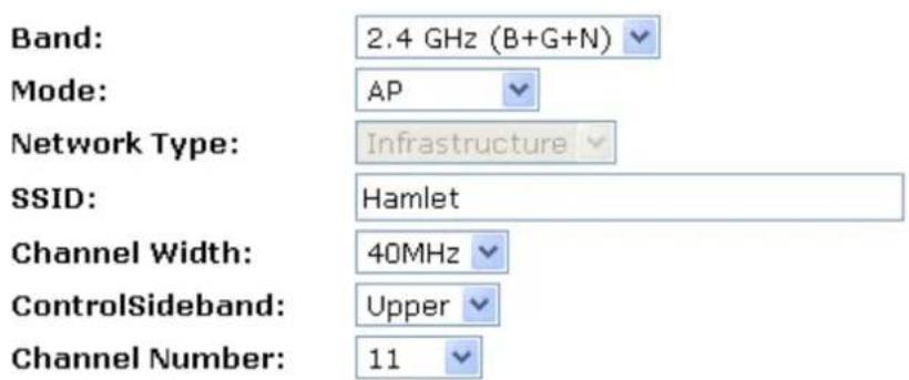
AP (Access Point)
Access Point is used to configure the parameters for wireless LAN clients who may connect to your Wi-Fi Router.
- From the Band drop-down list, select a Band.
- From the Mode drop-down list, select AP setting.
- Enter SSID for example 11n_AP_Router.
- From the Channel Width drop-down list, select a Channel Width.
- From the ControlSideband drop-down list, select a ControlSideband.
- From the Channel Number drop-down list, select a Channel Number.
- Click Next>>.
Quick Setup
Wireless Basic Settings
This page is used to configure the parameters for wireless LAN clients which may connect to your Access Point.
☐ Add to Wireless Profile

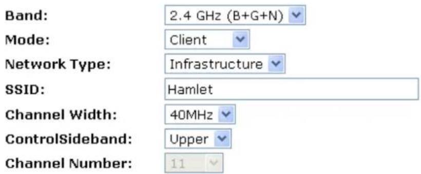
Client
This page is used to configure the parameters for wireless LAN clients which may connect to your Wi-Fi Router.
- From the Band drop-down list, select a Band.
- From the Mode drop-down list, select Client setting.
- From the Network Type drop-down list, select a Type.
- Enter SSID for example 11n_AP_Router.
- Click Next>>.
Quick Setup
Wireless Basic Settings
This page is used to configure the parameters for wireless LAN clients which may connect to your Access Point.
☐ Add to Wireless Profile

WDS (Wireless Distribution System)
WDS stands for Wireless Distribution System. It enables the Wi-Fi Routers (APs) to be connected wirelessly. Integrated Access Device can also provide you services of WDS.
Note: Integrated Access Device that supports WDS does not support security systems like WEP, WPA or WPA-Enterprise on a WDS network:
Sometimes you want to establish a multi-access point wireless network in your home or office, but you don't have Ethernet cabling running to the locations where you want to add the extra AP. After all, you may be using wireless because you don't have wires in place already.
One way to overcome this problem is to use a system built into Wireless Gateway that is known as Wireless Distribution System (WDS).
WDS basically creates a mesh network by providing a mechanism for access points to “talk” to each other as well as sending data to devices associated with them.
Note: WDS is based on some standardized 802.11 protocols, but there is no standardized way of implementing it that works across different AP and router vendors. So if you have a Wireless Gateway in one location and you want to create a WDS link to a other brand of router in another location (just to pick two brands at random), you probably won't be able to get it to work. You have your best luck when you use equipment from the same manufacturer
Note: When you use WDS as a repeater system, as described below, it effectively halves the data rate for clients connected to Integrated Wireless Gateway. That's because every bit of data needs to be sent twice (data is received by the AP and then retransmitted).
To configure WDS, you need to modify some settings on each AP within the network. Your exact steps (and the verbiage used) will vary from vendor to vendor. Generally, you'll see some settings like the following:
Main WDS station:
One of your WDS stations is the main base station for the WDS network. This AP is connected directly to your Internet connection, or connected to your router via a wired connection. The main station is the bridge to your Internet connection that all wireless traffic eventually flows through.
Repeater WDS stations:
In a simple, two-AP WDS network, the other “unwired” AP is a repeater. The repeater receives data from the main base station and relays the data to the wireless clients associated to the repeater station (and vice versa for data coming from the clients). If you have more than two APs, remote APs may be repeaters, or they may be relays that provide an intermediate stopping point for data if the repeater is too far away from the main station to communicate.
When you configure your main or base WDS station, take note of the channel you're set to and the ESSID or network name of your network. If your AP has any kind of channel auto configuration function that changes channels based on network conditions, be sure to disable this feature. If your main WDS station is also your network's router, make sure it's set up to distribute IP addresses in the network.
Note: Write down or otherwise take note of the MAC addresses of all of your WDS stations — many configuration software systems require you to know these addresses to make the configuration settings work. Write down the wireless MAC address (it's often on a sticker) and not the Ethernet MAC address
Turn on the WDS functionality in your main station (it's often labeled WDS, or may say something like Enable This Base Station As a WDS Main Base Station — that's the wording Apple uses for their AirPort Extreme products). When you turn on this functionality, the configuration software may ask you to identify the remote repeater(s). Have the MAC addresses of those repeaters handy in case you need them.
Depending upon how your software works, you may have to separately access the configuration software on the remote repeater APs to turn on WDS. Here are a few things to remember:
- You need to assign any other WDS stations to the same channel that your main base station is using. This is counterintuitive to many folks who have had the 802.11b/g “use channels 1, 6, and 11 and keep your APs on different channels” mantra driven into their heads for a long time!
- You set the ESSID of the remote location(s) using either a unique name or by using the same ESSID as you use for your main base station. (Whoa, our heads just exploded!) Using the same ESSID (a “roaming” network) is pretty cool. You associate with one AP one time and then your PC or Mac can associate with any AP on your WDS network without you having to do anything — it’s more seamless this way. But remember, you don’t have to do this — you can give each AP a unique ESSID and just configure your computer to associate with them according to your preference.
- Make sure you turn off any routing or DHCP functionality in the remote repeater stations. All of this functionality should be performed in the main base station or the network's main router.
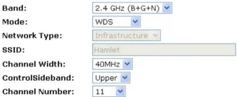
WDS (Wireless Distribution System) only
- From the Band drop-down list, select a Band.
- From the Mode drop-down list, select WDS setting.
- From the Channel Width drop-down list, select a Channel Width.
- From the ControlSideband drop-down list, select a ControlSideband.
- From the Channel Number drop-down list, select a Channel Number.
- Click Next>>.
Quick Setup
Wireless Basic Settings
This page is used to configure the parameters for wireless LAN clients which may connect to your Access Point.
☐ Add to Wireless Profile

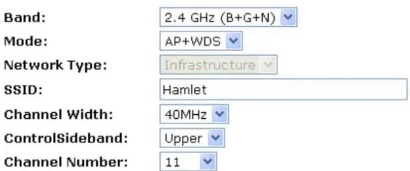
AP (Access Point) + WDS (Wireless Distribution System)
Access Point is used to configure the parameters for wireless LAN clients which may connect to your Wi-Fi Router.
- From the Band drop-down list, select a Band.
- From the Mode drop-down list, select AP+WDS setting.
- Enter SSID for example 11n_AP_Router.
- From the Channel Width drop-down list, select a Channel Width.
- From the ControlSideband drop-down list, select a ControlSideband.
- From the Channel Number drop-down list, select a Channel Number.
- Click Next>>.
Quick Setup
Wireless Basic Settings
This page is used to configure the parameters for wireless LAN clients which may connect to your Access Point.
☐ Add to Wireless Profile

8.4 Wireless Security Setup
This page allows you setup the wireless security. Turn on WEP or WPA by using Encryption Keys could prevent any unauthorized access to your wireless network.
Quick Setup
Wireless Security Setup
This page allows you setup the wireless security. Turn on WEP or WPA by using Encryption Keys could prevent any unauthorized access to your wireless network.
Encryption:
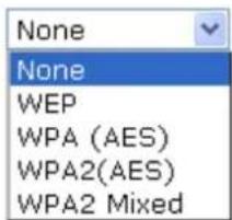

You can protect your wireless data from potential eavesdroppers by encrypting wireless data transmissions. An eavesdropper might set up a compatible wireless adapter within range of your device and attempt to access your network. Data encryption is the translation of data into a form that cannot be easily understood by unauthorized users.
There are two methods of wireless security to choose from:
- Wired Equivalent Privacy (WEP); data is encrypted into blocks of either 64 bits length or 128 bits length. The encrypted data can only be sent and received by users with access to a private network key. Each PC on your wireless network must be manually configured with the same key as your device in order to allow wireless encrypted data transmissions. Eavesdroppers cannot access your network if they do not know your private key. WEP is considered to be a low security option.
- Wi-Fi Protected Access (WPA); provides a stronger data encryption method (called Temporal Key Integrity Protocol (TKIP)). It runs in a special, easy-to-set-up home mode called Pre-Shared Key (PSK) that allows you to manually enter a pass phrase on all the devices in your wireless network. WPA data encryption is based on a WPA master key. The master key is derived from the pass phrase and the network name (SSID) of the device.
To configure security, choose one of the following options:
- If you do not want to use Wireless Network security, From the Encryption drop-down list, select None setting and then click Finished. None is the default setting, but you are strongly recommended to use wireless network security on your device.
- If you want to use WEP 64bit ASCII (5 characters) data encryption, follow the instructions in Configuring 64bit ASCII (5 characters) encryption.
- If you want to use WEP 64bit Hex (10 characters) data encryption, follow the instructions in Configuring WEP 64bit Hex (10 characters) security.
- If you want to use WEP 128bit ASCII (5 characters) data encryption, follow the instructions in Configuring WEP 128bit ASCII (5 characters) security.
- If you want to use WEP 128bit Hex (10 characters) data encryption, follow the instructions in Configuring WEP 128bit Hex (10 characters) security.
- If you want to use WPA (AES) - Wi-Fi Protected Access (AES) Passphrase encryption, follow the instructions in Configuring WPA (AES) Passphrase security.
- If you want to use WPA (AES) - Wi-Fi Protected Access (AES) HEX (64 characters) encryption, follow the instructions in Configuring WPA2 (AES) HEX (64 characters) security.
- If you want to use WPA2 (AES) - Wi-Fi Protected Access 2 (AES) Passphrase encryption, follow the instructions in Configuring WPA2 (AES) Passphrase security.
- If you want to use WPA2 (AES) - Wi-Fi Protected Access 2 (AES) HEX (64 characters) encryption, follow the instructions in Configuring WPA2 (AES) HEX (64 characters) security.
- If you want to use WPA2 Mixed-Wi-Fi Protected Access 2 (Mixed) Passphrase encryption, follow the instructions in Configuring WPA2 (Mixed) Passphrase security.
- If you want to use WPA2 Mixed-Wi-Fi Protected Access 2 (Mixed) HEX (64 characters) encryption, follow the instructions in Configuring WPA2 (Mixed) HEX (64 characters) security.
Configuring WEP 64bit ASCII (5 characters) security
The example set in this section is for 64bit encryption.
- From the Encryption drop-down list, select WEP setting.
- From the Key Length drop-down list, select 64-bit setting.
- From the Key Format drop-down list, select ASCII (5 characters) setting.
- Type the Key Setting.
- Click Finished.
Quick Setup
Wireless Security Setup
This page allows you setup the wireless security. Turn on WEP or WPA by using Encryption Keys could prevent any unauthorized access to your wireless network.
Encryption:
Key Length:
Key Format:
Key Setting:
WEP
64-bit
ASCII (5 characters)
The image contains no legible text or symbols. The OCR result "a" is a hallucination and does not correspond to any content in the source image. Therefore, the correct OCR output is an empty string.

- Change setting successfully! Please wait for a moment while rebooting.
Change setting successfully!
Please wait for a moment while rebooting ...
Configuring WEP 64bit Hex (10 characters) security
The example set in this section is for 64bit encryption.
- From the Encryption drop-down list, select WEP setting.
- From the Key Length drop-down list, select 64-bit setting.
- From the Key Format drop-down list, select Hex (10 characters) setting.
- Type the Key Setting.
- Click Finished.
Quick Setup
Wireless Security Setup
This page allows you setup the wireless security. Turn on WEP or WPA by using Encryption Keys could prevent any unauthorized access to your wireless network.
Encryption:
Key Length:
Key Format:
Key Setting:
WEP
64-bit
Hex (10 characters)
The image contains no legible text or symbols. The OCR result "the

- Change setting successfully! Please wait for a moment while rebooting.
Change setting successfully!
Please wait for a moment while rebooting ...
Configuring WEP 128bit ASCII (13 characters) security
The example set in this section is for 128bit encryption.
- From the Encryption drop-down list, select WEP setting.
- From the Key Length drop-down list, select 128-bit setting.
- From the Key Format drop-down list, select ASCII (13 characters) setting.
- Type the Key Setting.
- Click Finished.
Quick Setup
Wireless Security Setup
This page allows you setup the wireless security. Turn on WEP or WPA by using Encryption Keys could prevent any unauthorized access to your wireless network.
Encryption:
Key Length:
Key Format:
Key Setting:
WEP
128-bit
ASCII (13 characters)
※※※※※※※※※※※※※※
Cancel
<<Back
Finished
- Change setting successfully! Please wait for a moment while rebooting.
Change setting successfully!
Please wait for a moment while rebooting ...
Configuring WEP 128bit Hex (26 characters) security
The example set in this section is for 128bit encryption.
- From the Encryption drop-down list, select WEP setting.
- From the Key Length drop-down list, select 128-bit setting.
- From the Key Format drop-down list, select Hex (26 characters) setting.
- Type the Key Setting.
- Click Finished.
Quick Setup
Wireless Security Setup
This page allows you setup the wireless security. Turn on WEP or WPA by using Encryption Keys could prevent any unauthorized access to your wireless network.
Encryption:
Key Length:
Key Format:
Key Setting:
WEP
128-bit
Hex (26 characters)
- Change setting successfully! Please wait for a moment while rebooting.
Change setting successfully!
Please wait for a moment while rebooting ...
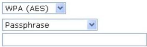
Configuring WPA (AES) Passphrase security
The example set in this section is for WPA (AES) Passphrase encryption..
- From the Encryption drop-down list, select WPA (AES) setting.
- From the Pre-Shared Key Format drop-down list, select Passphrase setting.
- Type the Pre-Shared Key.
- Click Finished.
Quick Setup
Wireless Security Setup
This page allows you setup the wireless security. Turn on WEP or WPA by using Encryption Keys could prevent any unauthorized access to your wireless network.
Encryption:
Pre-Shared Key Format:
Pre-Shared Key:

- Change setting successfully! Please wait for a moment while rebooting.
Change setting successfully!
Please wait for a moment while rebooting ...
Configuring WPA (AES) HEX (64 characters) security
The example set in this section is for WPA (TKIP) HEX (64 characters) encryption.
- From the Encryption drop-down list, select WPA (TKIP) setting.
- From the Pre-Shared Key Format drop-down list, select HEX (64 characters) setting.
- Type the Pre-Shared Key.
- Click Finished.
Quick Setup
Wireless Security Setup
This page allows you setup the wireless security. Turn on WEP or WPA by using Encryption Keys could prevent any unauthorized access to your wireless network.
Encryption:
WPA (AES)
Pre-Shared Key Format:
Hex (64 characters)
Pre-Shared Key:
Cancel <<Back Finished
- Change setting successfully! Please wait for a moment while rebooting.
Change setting successfully!
Please wait for a moment while rebooting ...
Configuring WPA2 (AES) Passphrase security
The example set in this section is for WPA2 (AES) Passphrase encryption.
- From the Encryption drop-down list, select WPA2 (AES) setting.
- From the Pre-Shared Key Format drop-down list, select Passphrase setting.
- Type the Pre-Shared Key.
- Click Finished.
Quick Setup
Wireless Security Setup
This page allows you setup the wireless security. Turn on WEP or WPA by using Encryption Keys could prevent any unauthorized access to your wireless network.
Encryption:
Pre-Shared Key Format:
Pre-Shared Key:
WPA2(AES)
Passphrase
01234657
Cancel
<<Back
Finished
- Change setting successfully! Please wait for a moment while rebooting.
Change setting successfully!
Please wait for a moment while rebooting ...
Configuring WPA2 (AES) HEX (64 characters) security
The example set in this section is for WPA2 (AES) HEX (64 characters) encryption.
- From the Encryption drop-down list, select WPA2 (AES) setting.
- From the Pre-Shared Key Format drop-down list, select HEX (64 characters) setting.
- Type the Pre-Shared Key.
- Click Finished.
Quick Setup
Wireless Security Setup
This page allows you setup the wireless security. Turn on WEP or WPA by using Encryption Keys could prevent any unauthorized access to your wireless network.
Encryption:
WPA2(AES)
Pre-Shared Key Format:
Hex (64 characters)
Pre-Shared Key:
012346578901234657890123465789
Cancel <<Back Finished
- Change setting successfully! Please wait for a moment while rebooting.
Change setting successfully!
Please wait for a moment while rebooting ...
Configuring WPA2 (Mixed) Passphrase security
The example set in this section is for WPA2 (Mixed) Passphrase encryption.
The WPA2 (Mixed) Passphrase encryption supports both WPA (TKIP) and WPA2 (AES).
- From the Encryption drop-down list, select WPA2 (Mixed) setting.
- From the Pre-Shared Key Format drop-down list, select Passphrase setting.
- Type the Pre-Shared Key.
- Click Finished.
Quick Setup
Wireless Security Setup
This page allows you setup the wireless security. Turn on WEP or WPA by using Encryption Keys could prevent any unauthorized access to your wireless network.
Encryption:
WPA2 Mixed

Pre-Shared Key Format:
Passphrase

Pre-Shared Key:
01234657
Cancel
<<Back
Finished
- Change setting successfully! Please wait for a moment while rebooting.
Change setting successfully!
Please wait for a moment while rebooting ...
Configuring WPA2 (Mixed) HEX (64 characters) security
The example set in this section is for WPA2 (Mixed) HEX (64 characters) encryption.
The WPA2 (Mixed) HEX (64 characters) encryption supports both WPA (TKIP) and WPA2 (AES).
- From the Encryption drop-down list, select WPA2 (Mixed) setting.
- From the Pre-Shared Key Format drop-down list, select HEX (64 characters) setting.
- Type the Pre-Shared Key.
- Click Finished.
Quick Setup
Wireless Security Setup
This page allows you setup the wireless security. Turn on WEP or WPA by using Encryption Keys could prevent any unauthorized access to your wireless network.
Encryption:
WPA2 Mixed
Pre-Shared Key Format:
Hex (64 characters)
Pre-Shared Key:
012346578901234657890123465789

- Change setting successfully! Please wait for a moment while rebooting.
Change setting successfully!
Please wait for a moment while rebooting ...
9. Operation Mode
This chapter describes how to configure the way that your device connects to the Internet. There are three options of Operation Mode: Gateway, Bridge and Wireless ISP.
9.1 Setting Operation Mode
To change the Operation Mode:
-
From the left-hand Operation Mode menu. The following page is displayed:
-
Click on the ratio of Gateway, Bridge or Wireless ISP and then click on Apply to active it.
Operation Mode
You can setup different modes to LAN and WLAN interface for NAT and bridging function.
Gateway:
In this mode, the device is supposed to connect to internet via ADSL/Cable Modem. The NAT is enabled and PCs in LAN ports share the same IP to ISP through WAN port. The connection type can be setup in WAN page by using PPPOE, DHCP client, PPTP client, L2TP client or static IP.
Bridge:
In this mode, all ethernet ports and wireless interface are bridged together and NAT function is disabled. All the WAN related function and firewall are not supported.
○ Wireless ISP:
In this mode, all ethernet ports are bridged together and the wireless client will connect to ISP access point. The NAT is enabled and PCs in ethernet ports share the same IP to ISP through wireless LAN. You must set the wireless to client mode first and connect to the ISP AP in Site-Survey page. The connection type can be setup in WAN page by using PPPOE, DHCP client, PPTP client, L2TP client or static IP.
Apply Change
Reset
10. Wireless Network
This chapter assumes that you have already set up your Wireless PCs and installed a compatible Wireless card on your device. See Configuring Wireless PCs.
10.1 Basic Settings
The Wireless Network page allows you to configure the Wireless features of your device. To access the Wireless Network Basic Settings page:
From the left-hand Wireless menu, click on Basic Settings. The following page is displayed:
Wireless Basic Settings
This page is used to configure the parameters for wireless LAN clients which may connect to your Access Point. Here you may change wireless encryption settings as well as wireless network parameters.

Disable Wireless LAN Interface
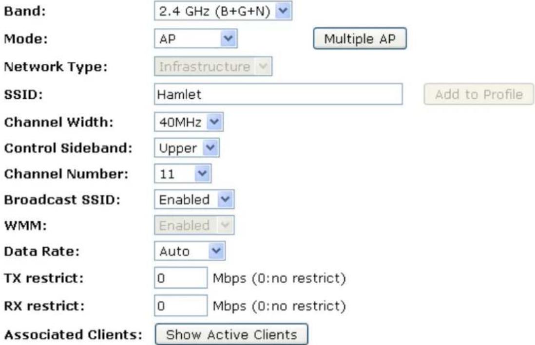


| Field | Description |
| Disable Wireless LAN Interface | Enable/Disable the Wireless LAN Interface.Default: Disable |
| Band | Specify the WLAN Mode to 802.11b/g Mixed mode, 802.11b mode or 802.11 mode |
| Mode | Configure the Wireless LAN Interface to AP, Client, WDS, AP + WDS, MESH or AP + MESH mode |
| Network Type | Configure the Network Type to Infrastructure or Ad hoc. |
| SSID | Specify the network name.Each Wireless LAN network uses a unique Network Name to identify the network. This name is called the Service Set Identifier (SSID). When you set up your wireless adapter, you specify the SSID. If you want to connect to an existing network, you must use the name for that network. If you are setting your own network you can make up your own name and use it on each computer. The name can be up to 20 characters long and contain letters and numbers. |
| Channel Width | Choose a Channel Width from the pull-down menu. |
| Control Sideband | Choose a Control Sideband from the pull-down menu. |
| Channel Number | Choose a Channel Number from the pull-down menu. |
| Broadcast SSID | Broadcast or Hide SSID to your Network.Default: Enabled |
| WMM | Enable/disable the Wi-Fi Multimedia (WMM) support. |
| Data Rate | Select the Data Rate from the drop-down list |
| Associated Clients | Show Active Wireless Client TableThis table shows the MAC address, transmission, reception packet counters and encrypted status for each associated wireless client. |
| Enable Mac Clone (Single Ethernet Client) | Enable Mac Clone (Single Ethernet Client) |
| Enable Universal Repeater Mode | Acting as AP and client simultaneously |
| SSID of Extended Interface | When mode is set to “AP” and URM (Universal Repeater Mode) is enabled, user should input SSID of another AP in the field of “SSID of Extended Interface”. Please note, the channel number should be set to the one, used by another AP because 8186 will share the same channel between AP and URI interface (called as extended interface hereafter). |
10.2 Advanced Settings
These settings are only for more technically advanced users who have a sufficient knowledge about wireless LAN. These settings should not be changed unless you know what effect the changes will have on your Wi-Fi Router. To access the Wireless Network Advanced Settings page:
From the left-hand Wireless menu, click on Advanced Settings. The following page is displayed:
Wireless Advanced Settings
These settings are only for more technically advanced users who have a sufficient knowledge about wireless LAN. These settings should not be changed unless you know what effect the changes will have on your Access Point.
| Fragment Threshold: | 2346 | (256-2346) |
| RTS Threshold: | 2347 | (0-2347) |
| Beacon Interval: | 100 | (20-1024 ms) |
| Preamble Type: | Long Preamble Short Preamble | |
| IAPP: | Enabled Disabled | |
| Protection: | Enabled Disabled | |
| Aggregation: | Enabled Disabled | |
| Short GI: | Enabled Disabled | |
| WLAN Partition: | Enabled Disabled | |
| STBC: | Enabled Disabled | |
| 20/40MHz Coexist: | Enabled Disabled | |
| RF Output Power: | 100% 70% 50% 35% 15% | |
Apply Changes
Reset
| Field | Description |
| Fragment Threshold | When transmitting a packet over a network medium, sometimes the packet is broken into several segments, if the size of packet exceeds that allowed by t network medium.The Fragmentation Threshold defines the number of bytes used for the fragmentation boundary for directed messages. |
| RTS Threshold | RTS stands for “Request to Send”. This parameter controls what size data packet the low level RF protocol issues to an RTS packet. The default is 234 |
| Beacon Interval | Choosing beacon period for improved response time for wireless http clients |
| Preamble Type | Specify the Preamble type is short preamble or long preamble |
| IAPP | Disable or Enable IAPP |
| Protection | A protection mechanism prevents collisions among 802.11g nodes. |
| Aggregation | Disable or Enable Aggregation |
| Short GI | Disable or Enable Short GI |
| WLAN Partition | Disable or Enable WLAN Partition |
| STBC | Disable or Enable STBC |
| 20/40MHz Coexist | Disable or Enable 20/40MHz Coexist |
| RF Output Power | TX Power measurement. |
10.3 Security
This page allows you to setup the wireless security. Turn on WEP or WPA by using Encryption Keys could prevent any unauthorized access to your wireless network. To access the Wireless Network Security page:
From the left-hand Wireless menu, click on Security. The following page is displayed:
Wireless Security Setup
This page allows you setup the wireless security. Turn on WEP or WPA by using Encryption Keys could prevent any unauthorized access to your wireless network.
Select SSID:
Root AP - Hamlet

Apply Changes
Reset
Encryption:
Disable

802.1x
Authentication:

| Field | Description |
| Select SSID | Select the SSID |
| Encryption | Configure the Encryption to Disable, WEP, WPA , WPA2 or WPA-Mixed |
| Use 802.1x Authentication | Use 802.1x Authentication by WEP 64bits or WEP 128bits |
| Authentication | Configure the Authentication Mode to Open System, Shared Key or Auto |
| Key Length | Select the Key Length 64-bit or 128-bit |
| Key Format | Select the Key Format ASCII (5 characters), Hex (10 characters), ASCII (13 characters) or Hex (26 characters) |
| Encryption Key | Enter the Encryption Key |
| WPA Authentication Mode | Configure the WPA Authentication Mode to Enterprise (RADIUS) or Persona (Pre-Shared Key) |
| WPA Cipher Suite | Configure the WPA Cipher Suite to TKIP and/or AES |
| WPA2 Cipher | Configure the WPA2 Cipher Suite to TKIP and/or AES |
| Suite | |
| Pre-Shared Key Format | Configure the Pre-Shared Key Format to Passphrase or HEX (64 characters) |
| Pre-Shared Key | Type the Pre-Shared Key |
| Enable Pre-Authentication | According to some of the preferred embodiments, a method for proactively establishing a security association between a mobile node in a visiting network and an authentication agent in another network to which the mobile node can move includes: negotiating pre-authentication using a flag in a message header that indicates whether the communication is for establishing a pre-authentication security association; and one of the mobile node and the authentication agent initiating pre-authentication by transmitting a message with the flag set in its message header, and the other of the mobile node and the authentication agent responding with the flag set in its message header only if it supports the pre-authentication. Enable/disable pre-authentication support. Default: disable. |
| Authentication RADIUS Server | Port: Type the port number of RADIUS ServerIP address: Type the IP address of RADIUS ServerPassword: Type the Password of RADIUS Server |
WEP + Encryption Key
WEP aims to provide security by encrypting data over radio waves so that it is protected as it is transmitted from one end point to another. However, it has been found that WEP is not as secure as once believed.
- From the Encryption drop-down list, select WEP setting.
- From the Key Length drop-down list, select 64-bit or 128-bit setting.
- From the Key Format drop-down list, select ASCII (5 characters), Hex (10 characters), ASCII (13 characters) or Hex (26 characters) setting.
- Enter the Encryption Key value depending on selected ASCII or Hexadecimal.
- Click Apply Changes button.
Wireless Security Setup
This page allows you setup the wireless security. Turn on WEP or WPA by using Encryption Keys could prevent any unauthorized access to your wireless network.
Select SSID: Root AP - Hamlet Apply Changes Reset
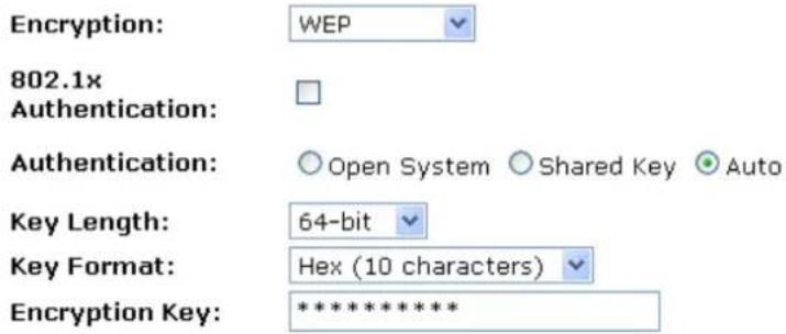
- Cliccate su OK.
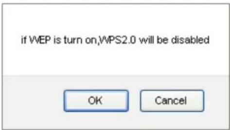
- Change setting successfully! Click on Reboot Now button to confirm.
Change setting successfully!
Your changes have been saved. The router must be rebooted for the changes to take effect. You can reboot now, or you can continue to make other changes and reboot later.
Reboot Now
Reboot Later
WEP + Use 802.1x Authentication
WEP aims to provide security by encrypting data over radio waves so that it is protected as it is transmitted from one end point to another. However, it has been found that WEP is not as secure as once believed.
- From the Encryption drop-down list, select WEP setting.
- Check the option of Use 802.1x Authentication.
- Click on the ratio of WEP 64bits or WEP 128bits.
- Enter the Port, IP Address and Password of RADIUS Server:
Authentication RADIUS Server: Port 1812 IP address 192.168.1.1 Password
- Click OK button.
Wireless Security Setup
This page allows you setup the wireless security. Turn on WEP or WPA by using Encryption Keys could prevent any unauthorized access to your wireless network.
Select SSID: Root AP - 11n_AP_Router
Apply Changes Reset
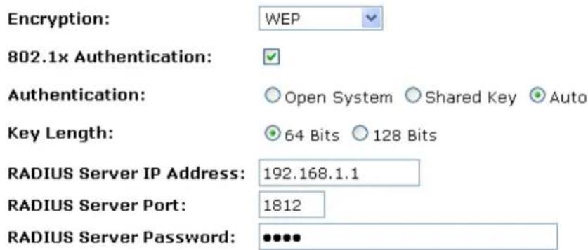
- Click OK button
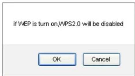
- Change setting successfully! Click on Reboot Now button to confirm.
Change setting successfully!
Your changes have been saved. The router must be rebooted for the changes to take effect. You can reboot now, or you can continue to make other changes and reboot later.
Reboot Now
Reboot Later
WPA/WPA2/WPA2 Mixed + Personal (Pre-Shared Key)
Wi-Fi Protected Access (WPA and WPA2) is a class of systems to secure wireless (Wi-Fi) computer networks. WPA is designed to work with all wireless network interface cards, but not necessarily with first generation Wi-Fi AP Routers. WPA2 implements the full standard, but will not work with some older network cards. Both provide good security, with two significant issues:
- Either WPA or WPA2 must be enabled and chosen in preference to WEP. WEP is usually presented as the first security choice in most installation instructions.
-
In the "Personal" mode, the most likely choice for homes and small offices, a pass phrase is required that, for full security, must be longer than the typical 6 to 8 character passwords users are taught to employ.
-
From the Encryption drop-down list, select WPA, WPA2 or WPA2 Mixed setting.
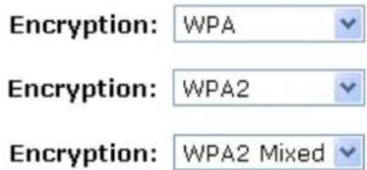
- Click on the ratio of Personal (Pre-Shared Key).
WPA Authentication Mode:
○ Enterprise (RADIUS) ◦ Personal (Pre-Shared Key)
- Check the option of TKIP and/or AES in WPA Cipher Suite if your Encryption is WPA:
WPA Cipher Suite:
TKIP AES
- Check the option of TKIP and/or AES in WPA2 Cipher Suite if your Encryption is WPA2:
WPA2 Cipher Suite:
TKIP AES
- Check the option of TKIP and/or AES in WPA/WPA2 Cipher Suite if your Encryption is WPA2 Mixed:
WPA Cipher Suite:
TKIP AES
WPA2 Cipher Suite:
TKIP AES
- From the Pre-Shared Key Format drop-down list, select Passphrase or Hex (64 characters) setting.
Pre-Shared Key Format:
Passphrase
Pre-Shared Key Format:
Hex (64 characters)
- Enter the Pre-Shared Key depending on selected Passphrase or Hex (64 characters).
Pre-Shared Key:
0123456789
-
Click on Apply Changes button to confirm and return.
-
Change setting successfully! Click on Reboot Now button to confirm.
WPA/WPA2/WPA2 Mixed + Enterprise (RADIUS)
Wi-Fi Protected Access (WPA and WPA2) is a class of systems to secure wireless (Wi-Fi) computer networks. WPA is designed to work with all wireless network interface cards, but not necessarily with first generation Wi-Fi AP Routers. WPA2 implements the full standard, but will not work with some older network cards. Both provide good security, with two significant issues:
- Either WPA or WPA2 must be enabled and chosen in preference to WEP. WEP is usually presented as the first security choice in most installation instructions.
-
In the "Personal" mode, the most likely choice for homes and small offices, a pass phrase is required that, for full security, must be longer than the typical 6 to 8 character passwords users are taught to employ.
-
From the Encryption drop-down list, select WPA, WPA2 or WPA2 Mixed setting.
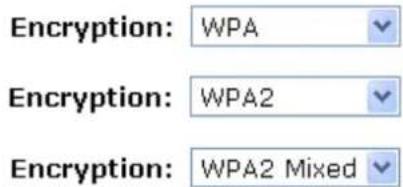
- Click on the ratio of Enterprise (RADIUS).
WPA Authentication Mode:
Enterprise (RADIUS)
○ Personal (Pre-Shared Key)
- Check the option of TKIP and/or AES in WPA Cipher Suite if your Encryption is WPA:
WPA Cipher Suite:
TKIP AES
- Check the option of TKIP and/or AES in WPA2 Cipher Suite if your Encryption is WPA2:
WPA2 Cipher Suite:
TKIP
AES
- Check the option of TKIP and/or AES in WPA/WPA2 Cipher Suite if your Encryption is WPA2 Mixed:
WPA Cipher Suite:
TKIP
AES
WPA2 Cipher Suite:
TKIP
AES
- Enter the Port, IP Address and Password of RADIUS Server:
Authentication RADIUS Server:
Port 1812
IP address 192.168.1.1
Password
●●●●●●
- Change setting successfully! Click on Reboot Now button to confirm.
Change setting successfully!
Your changes have been saved. The router must be rebooted for the changes to take effect. You can reboot now, or you can continue to make other changes and reboot later.
Reboot Now
Reboot Later
10.4 Access Control
For security reason, using MAC ACL's (MAC Address Access List) creates another level of difficulty to hacking a network. A MAC ACL is created and distributed to AP so that only authorized NICs can connect to the network. While MAC address spoofing is a proven means to hacking a network this can be used in conjunction with additional security measures to increase the level of complexity of the network security decreasing the chance of a breach.
MAC addresses can be add/delete/edit from the ACL list depending on the MAC Access Policy.
If you choose 'Allowed Listed', only those clients whose wireless MAC addresses are in the access control list will be able to connect to your Wi-Fi Router. When 'Deny Listed' is selected, these wireless clients on the list will not be able to connect the Wi-Fi Router. To access the Wireless Network Access Control page:
From the left-hand Wireless menu, click on Access Control. The following page is displayed:
Wireless Access Control
If you choose 'Allowed Listed', only those clients whose wireless MAC addresses are in the access control list will be able to connect to your Access Point. When 'Deny Listed' is selected, these wireless clients on the list will not be able to connect the Access Point.
Wireless Access Control Mode:
Disable
MAC Address:
Comment:
Apply Changes
Reset
Current Access Control List:

Allow Listed
If you choose 'Allowed Listed', only those clients whose wireless MAC addresses are in the access control list will be able to connect to your Wi-Fi Router.
- From the Wireless Access Control Mode drop-down list, select Allowed Listed setting.
- Enter the MAC Address.
- Enter the Comment.
- Click Apply Changes button.

- Change setting successfully! Click on Reboot Now button to confirm.
Change setting successfully!
Your changes have been saved. The router must be rebooted for the changes to take effect. You can reboot now, or you can continue to make other changes and reboot later.

- The MAC Address that you created has been added in the Current Access Control List.
Current Access Control List:
| MAC Address | Comment | Select |
| 00:11:22:33:44:55 | Test1 |
Deny Listed
When 'Deny Listed' is selected, these wireless clients on the list will not be able to connect the Wi-Fi Router.
- From the Wireless Access Control Mode drop-down list, select Deny Listed setting.
- Enter the MAC Address.
- Enter the Comment.
- Click Apply Changes button.

- Change setting successfully! Click on Reboot Now button to confirm.
Change setting successfully!
Your changes have been saved. The router must be rebooted for the changes to take effect. You can reboot now, or you can continue to make other changes and reboot later.
Reboot Now
Reboot Later
- The MAC Address that you created has been added in the Current Access Control List.
Current Access Control List:
| MAC Address | Comment | Select |
| 00:11:22:33:44:55 | Test1 |
10.5 WDS settings
Wireless Distribution System uses wireless media to communicate with other APs, like the Ethernet does. To do this, you must set these APs in the same channel and set MAC address of other APs which you want to communicate with in the table and then enable the WDS. To access the Wireless Network WDS settings page:
From the left-hand Wireless menu, click on WDS settings. The following page is displayed:
WDS Settings
Wireless Distribution System uses wireless media to communicate with other APs, like the Ethernet does. To do this, you must set these APs in the same channel and set MAC address of other APs which you want to communicate with in the table and then enable the WDS.
Enable WDS
MAC
Address:
Data Rate: Auto
Comment:
Apply Changes
Reset
Set Security
Show Statistics
Current WDS AP List:
| MAC Address | Tx Rate (Mbps) | Comment | Select |
Delete Selected
Delete All
Reset
Configure WDS (Wireless Distribution System) only
- From the left-hand Wireless menu, click on Basic Settings.
- From the Mode drop-down list, select WDS.
- From the Channel Number drop-down list, select a Channel.
- Click Apply Changes button.
Wireless Basic Settings
This page is used to configure the parameters for wireless LAN clients which may connect to your Access Point. Here you may change wireless encryption settings as well as wireless network parameters.
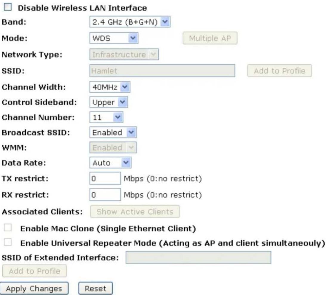
- Change setting successfully! Click on Reboot Now button to confirm.
Change setting successfully!
Your changes have been saved. The router must be rebooted for the changes to take effect. You can reboot now, or you can continue to make other changes and reboot later.
Reboot Now
Reboot Later
- From the left-hand Wireless menu, click on WDS settings.
- Check on the option Enable WDS.
- Enter the MAC Address.
- Enter the Comment.
- Click the Set Security.
WDS Settings
Wireless Distribution System uses wireless media to communicate with other APs, like the Ethernet does. To do this, you must set these APs in the same channel and set MAC address of other APs which you want to communicate with in the table and then enable the WDS.
Enable WDS
MAC Address: 001122334455
Data Rate: Auto
Comment: Test1
Apply Changes
Reset
Set Security
Show Statistics
Current WDS AP List:

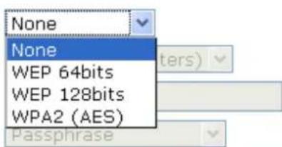
- This page allows you setup the wireless security for WDS. When enabled, you must make sure each WDS device has adopted the same encryption algorithm and Key.
- Configure each field with the Encryption that you selected.
- Click Apply Changes button.
WDS Security Setup
This page allows you setup the wireless security for WDS. When enabled, you must make sure each WDS device has adopted the same encryption algorithm and Key.
Encryption:
WEP Key Format:
WEP Key:
Pre-Shared Key Format:
Pre-Shared Key:
Apply Changes
Reset
- Change setting successfully! Click on Reboot Now button to confirm.
Change setting successfully!
Your changes have been saved. The router must be rebooted for the changes to take effect. You can reboot now, or you can continue to make other changes and reboot later.
Reboot Now
Reboot Later
- Click Close button to close and exit the WDS Security Setup.
WDS Security Setup
This page allows you setup the wireless security for WDS. When enabled, you must make sure each WDS device has adopted the same encryption algorithm and Key.
Encryption:
None

WEP Key Format:
ASCII (5 characters)
WEP Key:

Pre-Shared Key Format:
Passphrase
Pre-Shared Key:
Apply Changes
Reset
- Change setting successfully! Click on Reboot Now button to confirm.
Change setting successfully!
Your changes have been saved. The router must be rebooted for the changes to take effect. You can reboot now, or you can continue to make other changes and reboot later.
Reboot Now
Reboot Later
17. Click Apply Changes button.
WDS Settings
Wireless Distribution System uses wireless media to communicate with other APs, like the Ethernet does. To do this, you must set these APs in the same channel and set MAC address of other APs which you want to communicate with in the table and then enable the WDS.
Enable WDS
MAC
001122334455
Address:
Auto
Data Rate:
Test1
Apply Changes
Reset
Set Security
Show Statistics
Current WDS AP List:

- Change setting successfully! Click on Reboot Now button to confirm.
Change setting successfully!
Your changes have been saved. The router must be rebooted for the changes to take effect. You can reboot now, or you can continue to make other changes and reboot later.
Reboot Now
Reboot Later
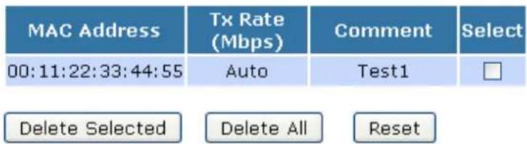
- The MAC Address that you created has been added in the Current Access Control List.
Current WDS AP List:
Configure AP (Access Point) + WDS (Wireless Distribution System)
- From the left-hand Wireless menu, click on Basic Settings.
- From the Mode drop-down list, select AP+WDS.
- Enter SSID for example 11n_AP_Router.
- From the Channel Number drop-down list, select a Channel.
- Click Apply Changes button.
Wireless Basic Settings
This page is used to configure the parameters for wireless LAN clients which may connect to your Access Point. Here you may change wireless encryption settings as well as wireless network parameters.
□ Disable Wireless LAN Interface
Band:
2.4 GHz (B+G+N)
Mode:
AP+WDS
Multiple AP
Network
Type:
Infrastructure
SSID:
11n_AP_Router
Channel Width:
40MHz
Control Sideband:
Upper
Channel Number:
11
Broadcast SSID:
Enabled
WMM:
Enabled
Data Rate:
Auto
Associated Clients:
Show Active Clients
Enable Mac Clone (Single Ethernet Client)
☐ Enable Universal Repeater Mode (Acting as AP and client simultaneously)
SSID of Extended Interface:
Apply Changes
Reset
- Change setting successfully! Click on Reboot Now button to confirm.
Change setting successfully!
Your changes have been saved. The router must be rebooted for the changes to take effect. You can reboot now, or you can continue to make other changes and reboot later.
Reboot Now
Reboot Later
- From the left-hand Wireless menu, click on WDS settings.
- Check on the option Enable WDS.
- Enter the MAC Address.
- Enter the Comment.
- Click the Set Security.
WDS Settings
Wireless Distribution System uses wireless media to communicate with other APs, like the Ethernet does. To do this, you must set these APs in the same channel and set MAC address of other APs which you want to communicate with in the table and then enable the WDS.
Enable WDS
MAC
001122334455
Address:
Data Rate: Auto
Comment: Test1
Apply Changes
Reset
Show Statistics
Set Security
Current WDS AP List:
- This page allows you setup the wireless security for WDS. When enabled, you must make sure each WDS device has adopted the same encryption algorithm and Key.
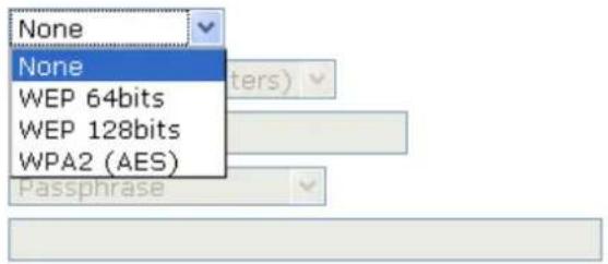
- Configure each field with the Encryption that you selected.
14. Click Apply Changes button.
WDS Security Setup
This page allows you setup the wireless security for WDS. When enabled, you must make sure each WDS device has adopted the same encryption algorithm and Key.
Encryption:
WEP Key Format:
WEP Key:
Pre-Shared Key Format:
Pre-Shared Key:
Apply Changes
Reset
15. Change setting successfully! Click on Reboot Now button to confirm.
Change setting successfully!
Your changes have been saved. The router must be rebooted for the changes to take effect. You can reboot now, or you can continue to make other changes and reboot later.
Reboot Now
Reboot Later
16. Click Close button to close and exit the WDS Security Setup.
WDS Security Setup
This page allows you setup the wireless security for WDS. When enabled, you must make sure each WDS device has adopted the same encryption algorithm and Key.
Encryption:
WEP Key Format:
WEP Key:
Pre-Shared Key Format:
Pre-Shared Key:
None

ASCII (5 characters)

Passphrase

Apply Changes
Reset
17. Click Apply Changes button.
WDS Settings
Wireless Distribution System uses wireless media to communicate with other APs, like the Ethernet does. To do this, you must set these APs in the same channel and set MAC address of other APs which you want to communicate with in the table and then enable the WDS.
Enable WDS
MAC
Address:
001122334455
Data Rate: Auto
Comment: Test1
Apply Changes
Reset
Set Security
Show Statistics
Current WDS AP List:
MAC Address
Tx Rate (Mbps)
Comment
Select
Delete Selected
Delete All
Reset
- Change setting successfully! Click on Reboot Now button to confirm.
Change setting successfully!
Your changes have been saved. The router must be rebooted for the changes to take effect. You can reboot now, or you can continue to make other changes and reboot later.
Reboot Now
Reboot Later
- The MAC Address that you created has been added in the Current Access Control List.
Current WDS AP List:
| MAC Address | Tx Rate (Mbps) | Comment | Select |
| 00:11:22:33:44:55 | Auto | Test1 | |
| Delete Selected | Delete All | Reset |
10.6 Site Survey
This page provides tool to scan the wireless network. If any Wi-Fi Router or IBSS is found, you could choose to connect it manually when client mode is enabled. To access the Wireless Network WDS settings page:
From the left-hand Wireless menu, click on Site Survey. The following page is displayed:
Wireless Site Survey
This page provides tool to scan the wireless network. If any Access Point or IBSS is found, you could choose to connect it manually when client mode is enabled.
Site Survey
| SSID | BSSID | Channel | Type | Encrypt | Signal |
| None |
Configure Wireless ISP + Wireless client + Site Survey
- From the left-hand Operation Mode menu, click on Wireless ISP Settings.
- Click Apply Changes button.
Operation Mode
You can setup different modes to LAN and WLAN interface for NAT and bridging function.
Gateway:
In this mode, the device is supposed to connect to internet via ADSL/Cable Modem. The NAT is enabled and PCs in LAN ports share the same IP to ISP through WAN port. The connection type can be setup in WAN page by using PPPOE, DHCP client, PPTP client, L2TP client or static IP.
○ Bridge:
In this mode, all ethernet ports and wireless interface are bridged together and NAT function is disabled. All the WAN related function and firewall are not supported.
Wireless ISP:
In this mode, all ethernet ports are bridged together and the wireless client will connect to ISP access point. The NAT is enabled and PCs in ethernet ports share the same IP to ISP through wireless LAN. You must set the wireless to client mode first and connect to the ISP AP in Site-Survey page. The connection type can be setup in WAN page by using PPPOE, DHCP client, PPTP client, L2TP client or static IP.
Apply Change
Reset
- Change setting successfully.
Change setting successfully!
Do not turn off or reboot the Device during this time.
Please wait 17 seconds ...
- From the left-hand Wireless menu, click on Basic Settings.
- From the Mode drop-down list, select Client.
- Enter SSID of the AP that you want to connect to for example 11n_AP_Router. If you don't know what the SSID of the AP that you want to connect to, please skip this step.
7. Click Apply Changes button.
Wireless Basic Settings
This page is used to configure the parameters for wireless LAN clients which may connect to your Access Point. Here you may change wireless encryption settings as well as wireless network parameters.
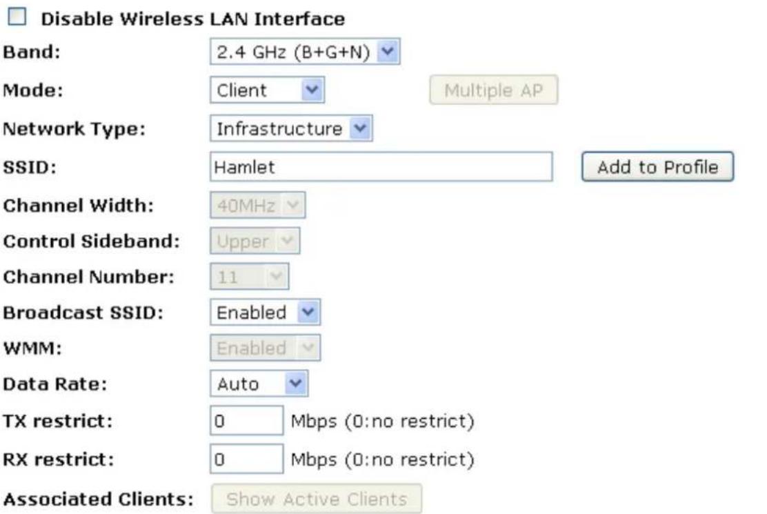
□ Enable Mac Clone (Single Ethernet Client) □ Enable Universal Repeater Mode (Acting as AP and client simultaneously)
SSID of Extended Interface: Add to Profile
□ Enable Wireless Profile Wireless Profile List:
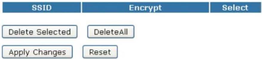
flowchart
graph TD
    A["SSID"] --> B["Delete Selected"]
    A --> C["DeleteAll"]
    A --> D["Apply Changes"]
    A --> E["Reset"]
    F["Encrypt"] --> G["Select"]
- Change setting successfully! Click on Reboot Now button to confirm.
Change setting successfully!
Your changes have been saved. The router must be rebooted for the changes to take effect. You can reboot now, or you can continue to make other changes and reboot later.
Reboot Now Reboot Later
- Change setting successfully.
Change setting successfully!
Do not turn off or reboot the Device during this time.
Please wait 17 seconds ...
- From the left-hand Wireless menu, click on Site Survey.
- Click Site Survey button.
Wireless Site Survey
This page provides tool to scan the wireless network. If any Access Point or IBSS is found, you could choose to connect it manually when client mode is enabled.
Site Survey
| SSID | BSSID | Channel | Type | Encrypt | Signal | Select |
| None |
Next>>
- Now you could see the APs that scanned by the Wireless Gateway were listed below.
- Click on the ratio of AP's SSID under the item Select that you want the Wireless Gateway to connect to.
14. Click Next button
Wireless Site Survey
This page provides tool to scan the wireless network. If any Access Point or IBSS is found, you could choose to connect it manually when client mode is enabled.
Site Survey
| SSID | BSSID | Channel | Type | Encrypt | Signal | Select |
| RA300R4G1 | 00:13:33:99:b6:ae | 9(B+G+N) | AP | no | 66 | |
| TW263R4 | 00:13:33:99:b8:13 | 6 (B+G) | AP | no | 46 | |
| D-Link TEST | 00:13:46:88:01:b4 | 1 (B+G) | AP | WPA-PSK/WPA2-PSK | 38 | |
| cchh | 00:13:33:9f:9a:9c | 8(B+G+N) | AP | WPA-PSK | 38 | |
| 3Com | 00:13:33:9a:aa:0a | 11(B+G+N) | AP | WEP | 32 | |
| 001601981740 | 00:16:01:98:17:41 | 3 (B+G) | AP | WEP | 28 | |
| carytrad | 00:1e:8c:bb:2c:5a | 6 (B+G) | AP | WEP | 24 | |
| OFFICE1 | 00:16:01:98:bc:e5 | 11(B+G) | AP | WPA-PSK | 18 |
Next>>
15. Click Next button.
Wireless Site Survey
This page provides tool to scan the wireless network. If any Access Point or IBSS is found, you could choose to connect it manually when client mode is enabled.
Encryption:
None

<<Back
Connect
- Connect successfully! Click on OK button to confirm and return.
Wireless Site Survey
This page provides tool to scan the wireless network. If any Access Point or IBSS is found, you could choose to connect it manually when client mode is enabled.
Please wait...
- Check on Add to Wireless Profile.
- Click Reboot Now button.
3.
Connect successfully!
Your changes have been saved. The router must be rebooted for the changes to take effect. You can reboot now, or you can continue to make other changes and reboot later.
Add to Wireless Profile
Reboot Now
Reboot Later
- Change setting successfully.
Change setting successfully!
Do not turn off or reboot the Device during this time.
Please wait 17 seconds ...
10.7 WPS
This page allows you to change the setting for WPS (Wi-Fi Protected Setup). Using this feature could let your wireless client automatically synchronize its setting and connect to the Wi-Fi Router in a minute without any hassle. To access the Wireless Network WPS page:
From the left-hand Wireless menu, click on WPS. The following page is displayed:
Wi-Fi Protected Setup
This page allows you to change the setting for WPS (Wi-Fi Protected Setup). Using this feature could let your wireless client automatically synchronize its setting and connect to the Access Point in a minute without any hassle.

Disable WPS
Apply Changes
Reset
WPS Status:
Configured
UnConfigured
Reset to UnConfigured
Unlock
Auto-lock-down state: unlocked
Self-PIN Number:
91261960
Push Button Configuration:
Start PBC
STOP WSC
Stop WSC
Client PIN Number:
Start PIN
| Field | Description |
| Disable WPS | · Checking this box and clicking “Apply Changes” will disable Wi-Fi Protected Setup. WPS is turned on by default. |
| WPS Status | · When AP’s settings are factory default (out of box), it is set to open security and un-configured state. It will be displayed by “WPS Status”. If it already shows “Configured”, some registrars such as Vista WCN will not configure AP. Users will need to go to the “Save/Reload Settings” page and click “Reset” to reload factory default settings. |
| Self-PIN Number | · “Self-PIN Number” is AP’s PIN. Whenever users want to change AP’s PIN, they could click “Regenerate PIN” and then click “Apply Changes”. Moreover, if users want to make their own PIN, they could en four digit PIN without checksum and then click “Apply Changes”. However, this would not be recommended since the registrar side needs to be supported with four digit PIN. |
| Push Button Configuration | Clicking this button will invoke the PBC method of WPS. It is only used when AP acts as a registrar. |
| Apply Changes | Whenever users want to enable/disable WPS or change AP’s PIN, they need to apply this button to commit changes. |
| Reset | It restores the original values of “Self-PIN Number” and “Client PIN Number”. |
| Client PIN Number | It is only used when users want their station to join AP’s network. The length of PIN is limited to four or eight numeric digits. If users enter eight digit PIN with checksum error, there will be a warning message popping up. If users insist on this PIN, AP will take it. |
Introduction of WPS
Although home Wi-Fi networks have become more and more popular, users still have trouble with the initial set up of network. This obstacle forces users to use the open security and increases the risk of eavesdropping. Therefore, WPS is designed to ease set up of security-enabled Wi-Fi networks and subsequently network management (Wi-Fi Protected Setup Specification 1.0h.pdf, p. 8).
The largest difference between WPS-enabled devices and legacy devices is that users do not need the knowledge about SSID, channel and security settings, but they could still surf in a security-enabled Wi-Fi network. For examples, in the initial network set up, if users want to use the PIN configuration, the only thing they need to do is entering the device PIN into registrar, starting the PIN method on that device and simply wait until the device joins the network. After the PIN method is started on both sides, a registration protocol will be initiated between the registrar and the enrollee. Typically, a registrar could be an access point or other device that is capable of managing the network. An enrollee could be an access point or a station that will join the network. After the registration protocol has been done, the enrollee will receive SSID and security settings from the registrar and then join the network. In other words; if a station attempts to join a network managed by an access point with built-in internal registrar, users will need to enter station's PIN into the web page of that access point. If the device PIN is correct and valid and users start PIN on station, the access point and the station will automatically exchange the encrypted information of the network settings under the management of AP's internal registrar. The station then uses this information to perform authentication algorithm, join the secure network, and transmit data with the encryption algorithm. More details will be demonstrated in the following sections.
Supported WPS features
Currently, Wireless Gateway supports WPS features for AP mode, AP+WDS mode, Infrastructure-Client mode, and the wireless root interface of Universal Repeater mode.
Other modes such as WDS mode, Infrastructure-Adhoc mode, and the wireless virtual interface of Universal Repeater mode are not implemented with WPS features.
If those unsupported modes are enforced by users, WPS will be disabled. Under the configuration of every WPS-supported mode, Wireless Gateway has Push Button method and PIN method. For each method, Wireless Gateway offers different security levels included in network credential, such as open security, WEP 64 bits, WEP 128 bits, WPA-Personal TKIP, WPA-Personal AES, WPA2-Personal TKIP, and WPA2-Personal AES. Users could choose either one of the methods at their convenience.
AP mode
For AP mode, Wireless Gateway supports three roles, registrar, proxy, and enrollee in registration protocol. At different scenarios, Wireless Gateway will automatically switch to an appropriate role depending on the other device's role or a specific configuration.
AP as Enrollee
If users know AP's PIN and enter it into external registrar, the external registrar will configure AP with a new wireless profile such as new SSID and new security settings. The external registrar does this job either utilizing the in-band EAP (wireless) or out-of-band UPnP (Ethernet). During the WPS handshake, a wireless profile is encrypted and transmitted to AP. If the handshake is successfully done, AP will be re-initialized with the new wireless profile and wait for legacy stations or WPS stations to join its network.
AP as Registrar
Wireless Gateway also has a built-in internal registrar. Whenever users enter station's PIN into AP's webpage, click "Start PBC", or push the physical button, AP will switch to registrar automatically. If users apply the same method on station side and the WPS handshake is successfully done, SSID and security settings will be transmitted to that station without the risk of eavesdropping. And then the station will associate with AP in a security-enabled network.
AP as Proxy
At this state, AP is transparent to users. If users want to configure a station or any device that is capable of being an enrollee, they have to enter device's PIN into an external registrar and choose an appropriate wireless profile. After the PIN is entered, the external registrar will inform AP this event. AP then conveys the encrypted wireless profile between the device and the external registrar. Finally, the device will use the wireless profile and associate with AP. However, the device may connect to other APs if the wireless profile does not belong to the proxy AP. Users must carefully choose the wireless profile or create a wireless profile on an external registrar.
Infrastructure-Client mode
In Infrastructure-Client mode, Wireless Gateway only supports enrollee's role. If users click "Start PIN", click "Start PBC", or press the physical button on Wireless Gateway, it will start to seek WPS AP. Once users apply the same method on registrar side, Wireless Gateway will receive the wireless profile upon successfully doing the registration protocol. Then Wireless Gateway will associate with an AP.
Instructions of AP's and Client's operations
At this state, AP is transparent to users. If users want to configure a station or any device that is capable of being an enrollee, they have to enter device's PIN into an external registrar and choose an appropriate wireless profile. After the PIN is entered, the external registrar will inform AP this event. AP then conveys the encrypted wireless profile between the device and the external registrar. Finally, the device will use the wireless profile and associate with AP. However, the device may connect to other APs if the wireless profile does not belong to the proxy AP. Users must carefully choose the wireless profile or create a wireless profile on an external registrar.
Wireless Advanced Settings page
Users need to make sure the "Broadcast SSID" file is set to "Enabled". Otherwise, it might prevent WPS from working properly.
Wireless Advanced Settings
These settings are only for more technically advanced users who have a sufficient knowledge about wireless LAN. These settings should not be changed unless you know what effect the changes will have on your Access Point.
Fragment Threshold:
RTS Threshold:
Beacon Interval:
Preamble Type:
IAPP:
Protection:
Aggregation:
Short GI:
WLAN Partition:
STBC:
LDPC:
20/40MHz Coexist:
RF Output Power:
2346 (256-2346)
2347 (0-2347)
100 (20-1024 ms)
Long Preamble
Enabled
Enabled
Enabled
Enabled
Enabled
Enabled
Enabled
Enabled
100%
○ Short Preamble
○ Disabled
Disabled
○ Disabled
○ Disabled
Disabled
Disabled
Disabled
Disabled
70%
50%
35%
15%
Apply Changes
Reset
10.8 Operations of AP - AP being an enrollee
In this case, AP will be configured by any registrar either through in-band EAP or UPnP. Here, users do not need to do any action on AP side. They just need AP's device PIN and enter it into registrar. An example from Vista WCN will be given.
- From the left-hand Wireless -> WPS menu. The following page is displayed:
- Make sure AP is in un-configured state.
Wi-Fi Protected Setup
This page allows you to change the setting for WPS (Wi-Fi Protected Setup). Using this feature could let your wireless client automatically synchronize its setting and connect to the Access Point in a minute without any hassle.
□ Disable WPS
Apply Changes
Reset
WPS Status:
Configured
UnConfigured
Reset to UnConfigured
Auto-lock-down state: unlocked
Unlock
Self-PIN Number:
91261960
Push Button Configuration:
Start PBC
STOP WSC
Stop WSC
Client PIN Number:
Start PIN
- Plug the Ethernet cable into AP's LAN port and make sure the IP connection is valid with Vista.
- Make sure WCN is enabled. Users may need to enable it at the first time. They could open the "Control Panel", click "Classic View", open "Administrative Tools", double click "Services", a User Account Control pop up and click "Continue", edit properties of "Windows Connect Now", choose the "Startup type" with "Automatic" and click "Start".
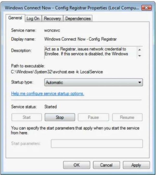
- If the previous steps are done, open Windows Explorer. Go to the Network section.
- Click on "Network discovery and file sharing are turned off. Network computers and devices are not visible. Click to Change..."
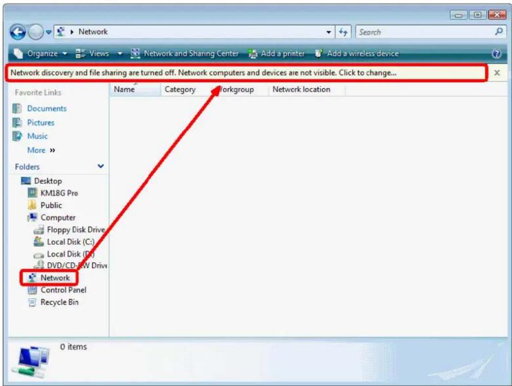
- Click on "Turn on network discovery and file sharing"
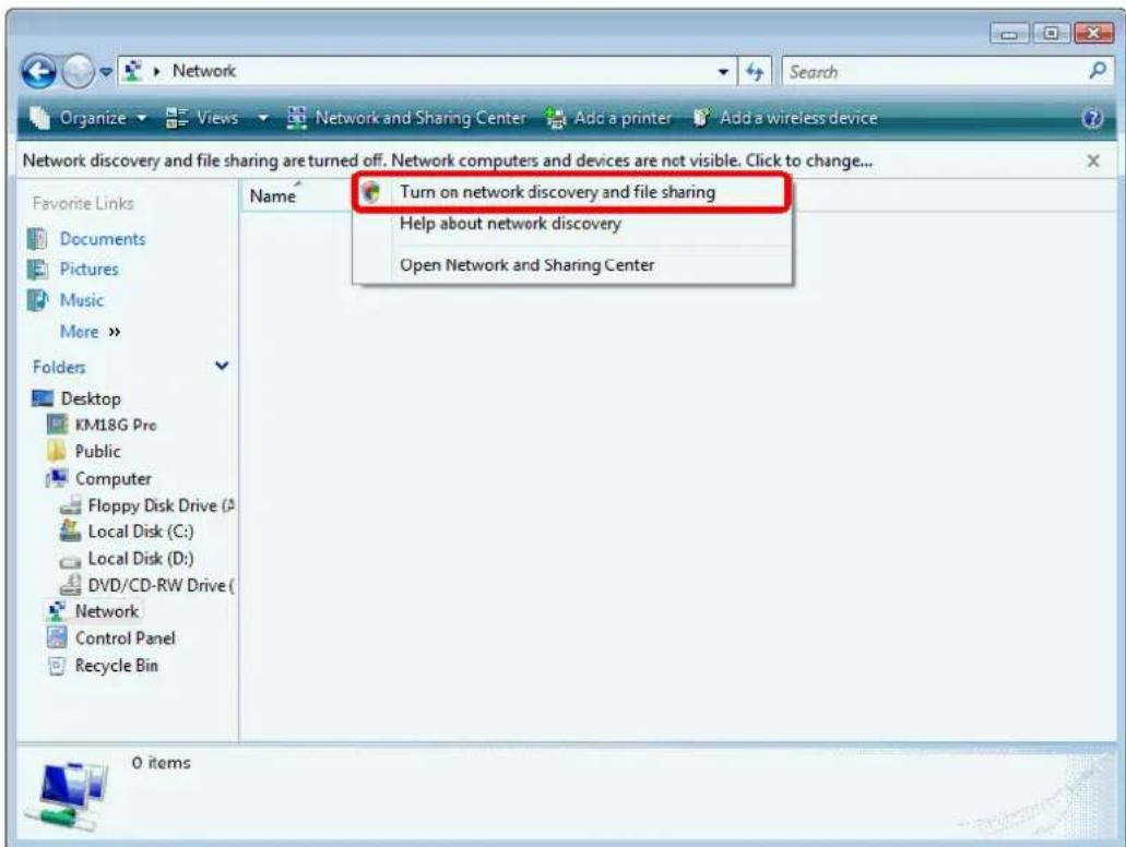
- Click on "No, make the network that I am connected to a private network"
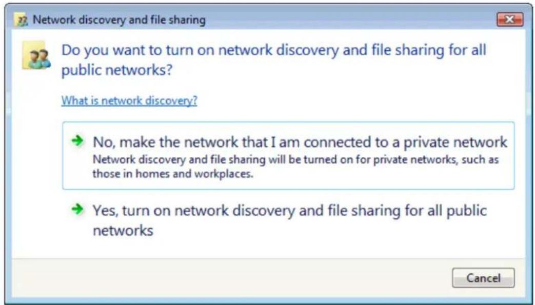
- AP's icon will show up. Double click on it.
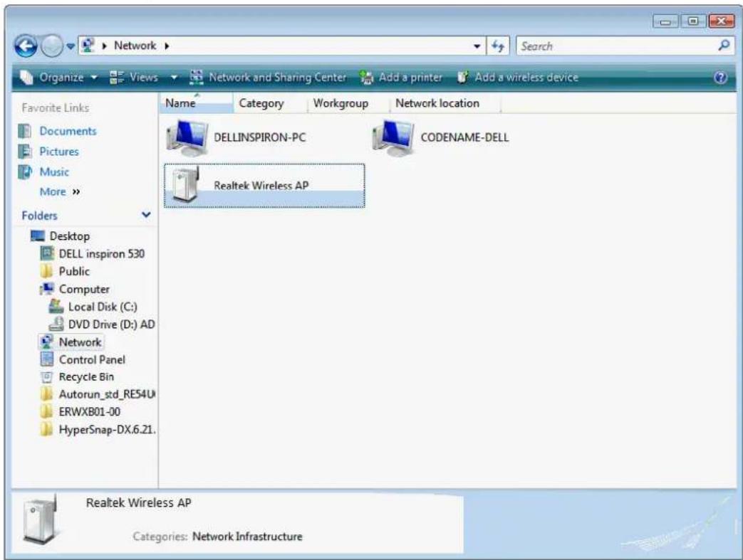
- Users could also Click "Add a wireless device" if the icon is not there. Click "next".
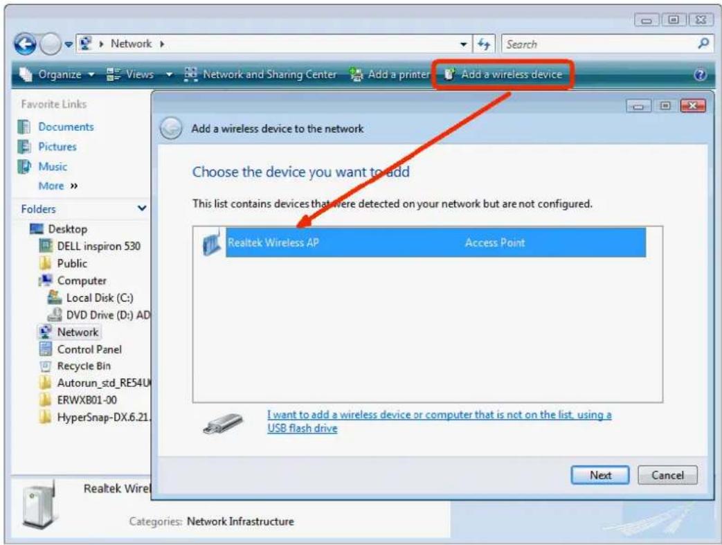
- Enter AP's Self-PIN Number and click "Next".
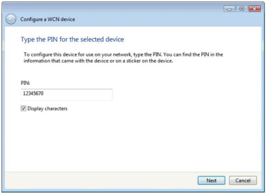
- Choose a name that people who connect to your network will recognize.
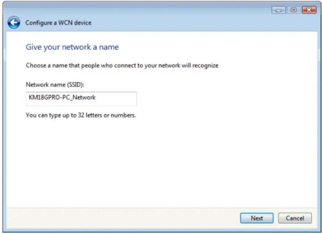
- Enter the Passphrase and then click "Next".
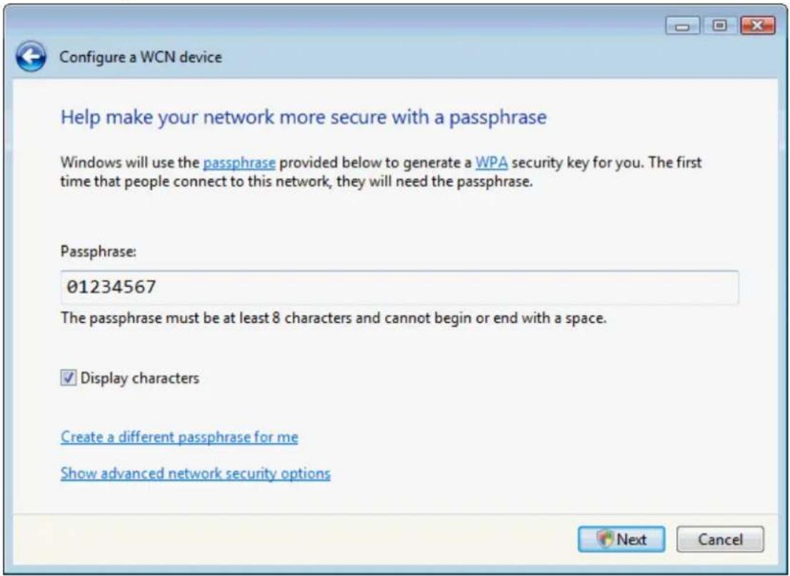
- A User Account Control screen pops up, click Continue.
- AP is successfully configured by WCN.
- Finally, AP will become configured (see WPS Status). The authentication algorithm, encryption algorithm, and key assigned by WCN will be displayed below "Current Key Info".
Wi-Fi Protected Setup
This page allows you to change the setting for WPS (Wi-Fi Protected Setup). Using this feature could let your wireless client automatically synchronize its setting and connect to the Access Point in a minute without any hassle.
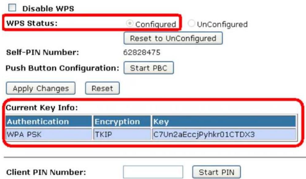
- The SSID field of Wireless Basic Settings page will also be modified with the value assigned by WCN.
Wireless Basic Settings
This page is used to configure the parameters for wireless LAN clients which may connect to your Access Point. Here you may change wireless encryption settings as well as wireless network parameters.
□ Disable Wireless LAN Interface
Band: 2.4 GHz (B+G+N)
Mode: AP Multiple AP
Network Type: Infrastructure
SSID: KM18GPRO-PC_Network
Channel Width: 40MHz
Control Sideband: Upper
Channel Number: 11
Broadcast SSID: Enabled
WMM: Enabled
Data Rate: Auto
Associated Clients: Show Active Clients
Enable Mac Clone (Single Ethernet Client)
☐ Enable Universal Repeater Mode (Acting as AP and client simultaneously)
SSID of Extended Interface:
Apply Changes
Reset
- The security settings on the Wireless Security Page will be modified by WCN, too. The warning message will show up if users try to modify the security settings. The reason is the same as we explained in the previous section.
Wireless Security Setup
This page allows you setup the wireless security. Turn on WEP or WPA by using Encryption Keys could prevent any unauthorized access to your wireless network.
Select SSID: Root AP - DELLINSPIRON-PC_Network
Apply Changes
Reset
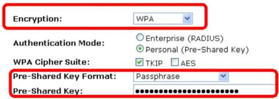
10.9 Operations of AP - AP being a registrar
AP mode
Whenever users enter station's PIN into AP's Wi-Fi Protected Setup page and click "Start PIN", AP will become a registrar. Users must start the PIN method on the station side within two minutes.
- From the left-hand Wireless -> WPS menu. The following page is displayed:
- Make sure AP is in un-configured state.
- Enter the Client PIN Number.
- Click Start PIN.
Wi-Fi Protected Setup
This page allows you to change the setting for WPS (Wi-Fi Protected Setup). Using this feature could let your wireless client automatically synchronize its setting and connect to the Access Point in a minute without any hassle.
□ Disable WPS
Apply Changes
Reset
WPS Status:
○ Configured ◦ UnConfigured
Reset to UnConfigured
Auto-lock-down state: unlocked
Unlock
Self-PIN Number:
02271385
Push Button Configuration:
Start PBC
STOP WSC
Stop WSC
Client PIN Number:
Start PIN
- Users must start the PIN method on the station side within two minutes.
Applied client's PIN successfully!
You have to run Wi-Fi Protected Setup in client within 2 minutes.
OK
- Users must start the PIN method on the station side within two minutes.
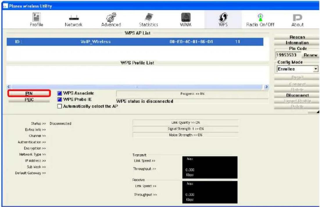
- If the device PIN is correct and the WPS handshake is successfully done on the station side, User's Wi-Fi Protected status will be shown as below.
![Planex wireless Utility Profile Network Advanced Statistics WAM WPS Radio On/Off About WPS AP List ID: 0x0000 VoIP_Wireless 00-E0-4C-81-86-D1 11 WPS Profile List WPS693e0786d1 PIN WPS Associate Progress >> 100% PBC WPS Probe IE WPS status is connected successfully - WPS693e0786d1 Automatically select the AP Status >> WPS693e0786d1 <= 00-E0-4C-81-86-D1 Extra Info >> Link is Up [TxPower 100%] Channel >> 11 <= 2462 MHz Authentication >> WPA2-PSK Encryption >> AES Network Type >> Infrastructure IP Address >> 10.0.0.102 Sub Work >> 255.0.0.0 Default Gateway >> 10.0.0.2 Link Quality >> 100% Noise Strength 1 <= 100% Noise Strength >> 70% Transmit Link Speed >> 54.0 Mbps Max Throughput >> 3.456 Kbps E1,584 Kbps Receive Link Speed >> 54.0 Mbps Max Throughput >> 21.960 Kbps 1.464 Mbps](/content/2026/05/1067938/images/567e0da418da1ff926cf581d4d2ae56f09be9dd1391ceec89aa62e9d8a73ee98.jpg)
- If the device PIN is correct and the WPS handshake is successfully done, AP's Wi-Fi Protected Setup page will be shown as below.
Wi-Fi Protected Setup
This page allows you to change the setting for WPS (Wi-Fi Protected Setup). Using this feature could let your wireless client automatically synchronize its setting and connect to the Access Point in a minute without any hassle.
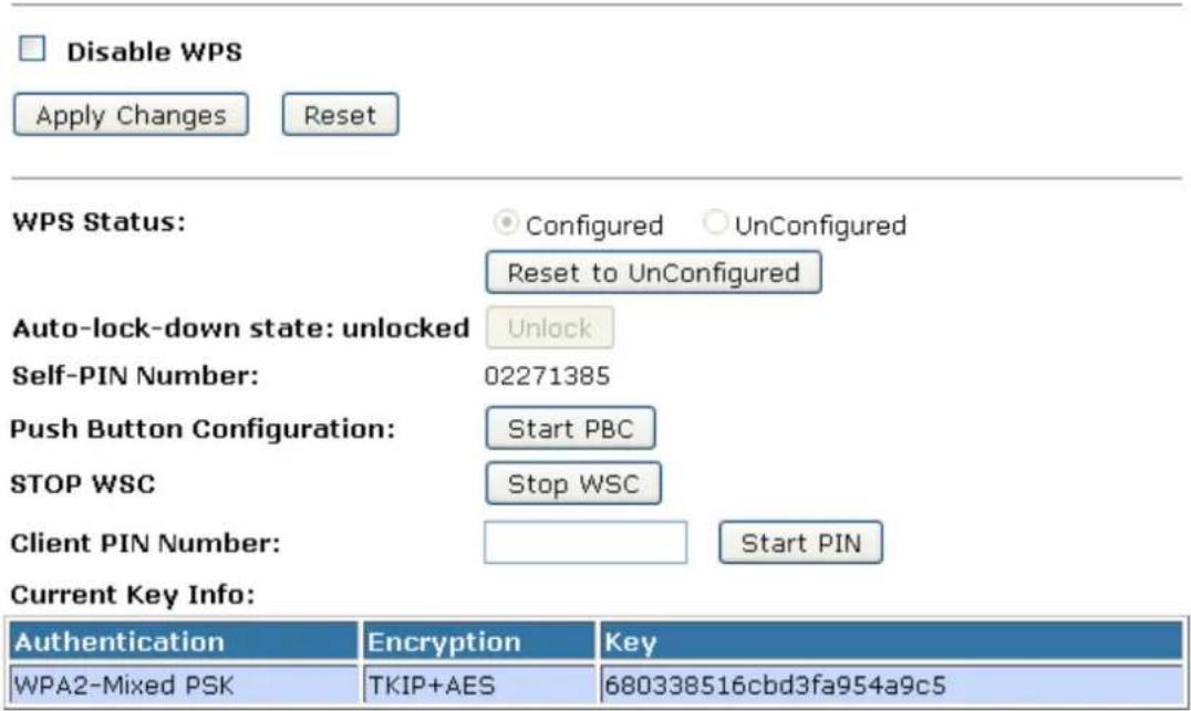
Other pages such as Wireless Basic Settings page and Wireless Security Setup page will also be updated appropriately as described in previous sections. In this case, AP is in un-configured state before the station initiates the WPS handshake. According to the WPS spec, AP will create a wireless profile with WPA2-mixed mode and a random-generated key upon successfully doing the WPS handshake. However, AP will use the original wireless profile and give it to the station if AP is already in configured state. That means all settings of AP will not change. Hence, all WPS related pages keep the same.
Push Button method
Wireless Gateway supports a virtual button "Start PBC" on the Wi-Fi Protected Setup page for Push Button method. If users push a virtual button "Start PBC", AP will initiate a WPS session and wait for any station to join. At this moment, AP will detect whether there is more than one station that starts the PBC method. When multiple PBC sessions occur, users should try PIN method.
After users push AP's virtual button "Start PBC", they must go to station side to push its button within two minutes. If the WPS is successfully done, AP will give its wireless profile to that station. The station could use this profile to associate with AP.
- From the left-hand Wireless -> WPS menu. The following page is displayed:
- Make sure AP is in un-configured state.
- Click Start PBC.
Wi-Fi Protected Setup
This page allows you to change the setting for WPS (Wi-Fi Protected Setup). Using this feature could let your wireless client automatically synchronize its setting and connect to the Access Point in a minute without any hassle.

Disable WPS
Apply Changes
Reset
WPS Status:
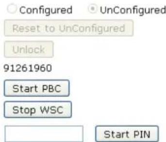
Auto-lock-down state: unlocked
Self-PIN Number:
Push Button Configuration:
STOP WSC
Client PIN Number:
Start PIN
- Users must start the PBC method on the station side within two minutes.
Start PBC successfully!
You have to run Wi-Fi Protected Setup in client within 2 minutes.
OK
- Users must start the PBC method on the station side within two minutes.
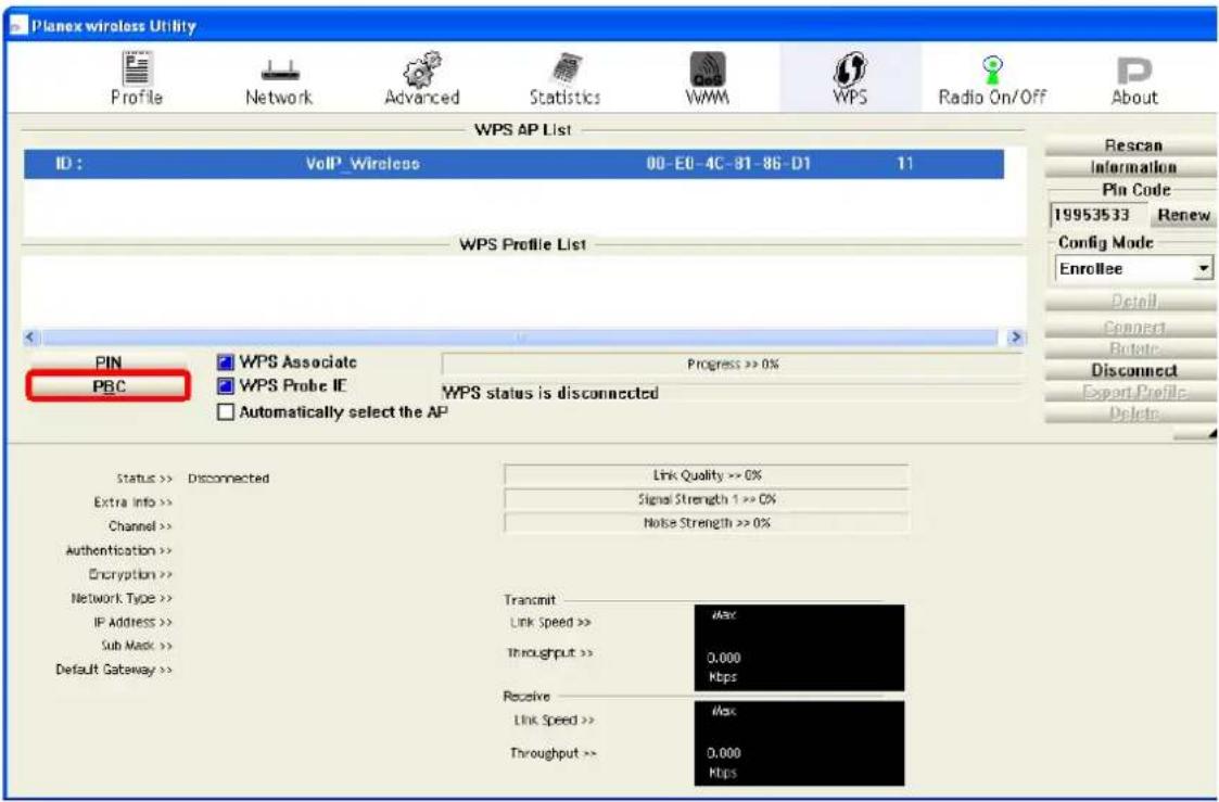
- If the device PBC and the WPS handshake are successfully done on the station side, User's Wi-Fi Protected status will be shown as below.
![Planex wireless Utility Profile Network Advanced Statistics WMM WPS Radio On/Off About WPS AP List ID: 0x0000 VoIP_Wireless 00-EO-4C-81-86-D1 11 WPS Profile List WPS693e0786d1 PIN PBC WPS Associate Progress >> 100% WPS Probe IE WPS status is connected successfully - WPS693e0786d1 Automatically select the AP Status >> WPS693e0786d1 <-> 00-EO-4C-81-86-D1 Extra Info >> Link Is Up [TxPower:100%] Channel >> 11 <-> 2462 MHz Authentication >> WPA2-PSK Encryption >> AES Network Type >> Infrastructure IP Address >> 10.0.0.102 Sub Max >> 265.0.0.0 Default Gateway >> 10.0.0.2 Line Quality >> 100% Signal Strength >> 100% Noise Strength >> 70% Transmit Link Speed >> 54.0 Mbps Throughput >> 3.456 Kbps Max 51,504 Kbps Receive Link Speed >> 54.0 Mbps Throughput >> 21,960 Kbps Max 1.464 Mbps](/content/2026/05/1067938/images/ba33ef18b5fa50e925272939fba8a51a87fe60832cda34ab27896e3d47e71135.jpg)
- If the device PIN is correct and the WPS handshake is successfully done, AP's Wi-Fi Protected Setup page will be shown as below.
Wi-Fi Protected Setup
This page allows you to change the setting for WPS (Wi-Fi Protected Setup). Using this feature could let your wireless client automatically synchronize its setting and connect to the Access Point in a minute without any hassle.
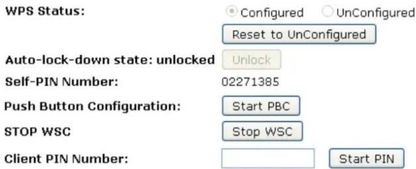
Current Key Info:
| Authentication | Encryption | Key |
| WPA2-Mixed PSK | TKIP+AES | 680338516cbd3fa954a9c5 |
Other pages such as Wireless Basic Settings page and Wireless Security Setup page will also be updated appropriately as described in previous sections. In this case, AP is in un-configured state before the station initiates the WPS handshake. According to the WPS spec, AP will create a wireless profile with WPA2-mixed mode and a random-generated key upon successfully doing the WPS handshake. However, AP will use the original wireless profile and give it to the station if AP is already in configured state. That means all settings of AP will not change. Hence, all WPS related pages keep the same.
10.10 Wireless Schedule
This page allows you setup the wireless schedule rule. Please do not forget to configure system time before enable this feature. To access the Wireless Schedule page:
From the left-hand Wireless menu, click on Wireless Schedule. The following page is displayed:
Wireless Schedule
This page allows you setup the wireless schedule rule. Please do not forget to configure system time before enable this feature.

Enable Wireless Schedule
| Enable | Day | From | To | ||||||
| Sun | √ | 00 | (hour) | 00 | (min) | 00 | (hour) | 00 | |
| Sun | √ | 00 | (hour) | 00 | (min) | 00 | (hour) | 00 | |
| Sun | √ | 00 | (hour) | 00 | (min) | 00 | (hour) | 00 | |
| Sun | √ | 00 | (hour) | 00 | (min) | 00 | (hour) | 00 | |
| Sun | √ | 00 | (hour) | 00 | (min) | 00 | (hour) | 01 | |
| Sun | √ | 00 | (hour) | 00 | (min) | 00 | (hour) | 00 | |
| Sun | √ | 00 | (hour) | 00 | (min) | 00 | (hour) | 00 | |
| Sun | √ | 00 | (hour) | 00 | (min) | 00 | (hour) | 00 | |
| Sun | √ | 00 | (hour) | 01 | (min) | 00 | (hour) | 00 | |
| Sun | √ | 00 | (hour) | 00 | (min) | 00 | (hour) | 00 | |
| Sun | √ | 00 | (hour) | 00 | (min) | 00 | (hour) | 00 | |
Apply Changes Reset
11. LAN Interface
This chapter is to configure the parameters for local area network which connects to the LAN port of your Wi-Fi Router. Here you may change the setting for IP address, subnet mask, DHCP, etc...
Note: You should only change the addressing details if your ISP asks you to, or if you are familiar with network configuration. In most cases, you will not need to make any changes to this configuration.
11.1 LAN Interface Setup
To check the configuration of LAN Interface:
- From the left-hand Network Settings -> LAN Interface menu. The following page is displayed:
LAN Interface Setup
This page is used to configure the parameters for local area network which connects to the LAN port of your Access Point. Here you may change the setting for IP address, subnet mask, DHCP, etc..
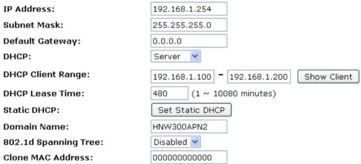
Apply Changes Reset
| Field | Description |
| IP Address | The LAN IP addressDefault: 192.168.1.254 |
| Subnet Mask | The LAN netmaskDefault: 255.255.255.0 |
| Default Gateway | The LAN GatewayDefault: 0.0.0.0 |
| DHCP | DHCP Type: Disable, DHCP Client or ServerDefault: DHCP Server |
| DHCP Client Range | Specify the starting/ending IP address of the IP address pool.Default Start IP: 192.168.1.100Default Ending IP: 192.168.1.200 |
| DHCP Lease Time | Configure DHCP Lease Time |
| Show Client | DHCP client computers/devices connected to the device will have their information displayed in the DHCP Client List table. The table will show the IP Address, MAC Address, and Expired Time of the DHCP lease for each client computer/device. |
| Domain Name | A domain name is a user-friendly name used in place of its associated IP address. Domain names must be unique; their assignment is controlled by the Internet Corporation for Assigned Names and Numbers (ICANN). Domain names are a key element of URLs, which identify a specific file as a web site. |
| 802.1d Spanning Tree | Enable or Disable Spanning Tree |
| Clone MAC Address | MAC Spoofing on LANDefault: 000000000000 |
11.2 Changing the LAN IP address and subnet mask
To check the configuration of LAN Interface:
- From the left-hand Network Settings -> LAN Interface menu. The following page is displayed:
LAN Interface Setup
This page is used to configure the parameters for local area network which connects to the LAN port of your Access Point. Here you may change the setting for IP address, subnet mask, DHCP, etc..
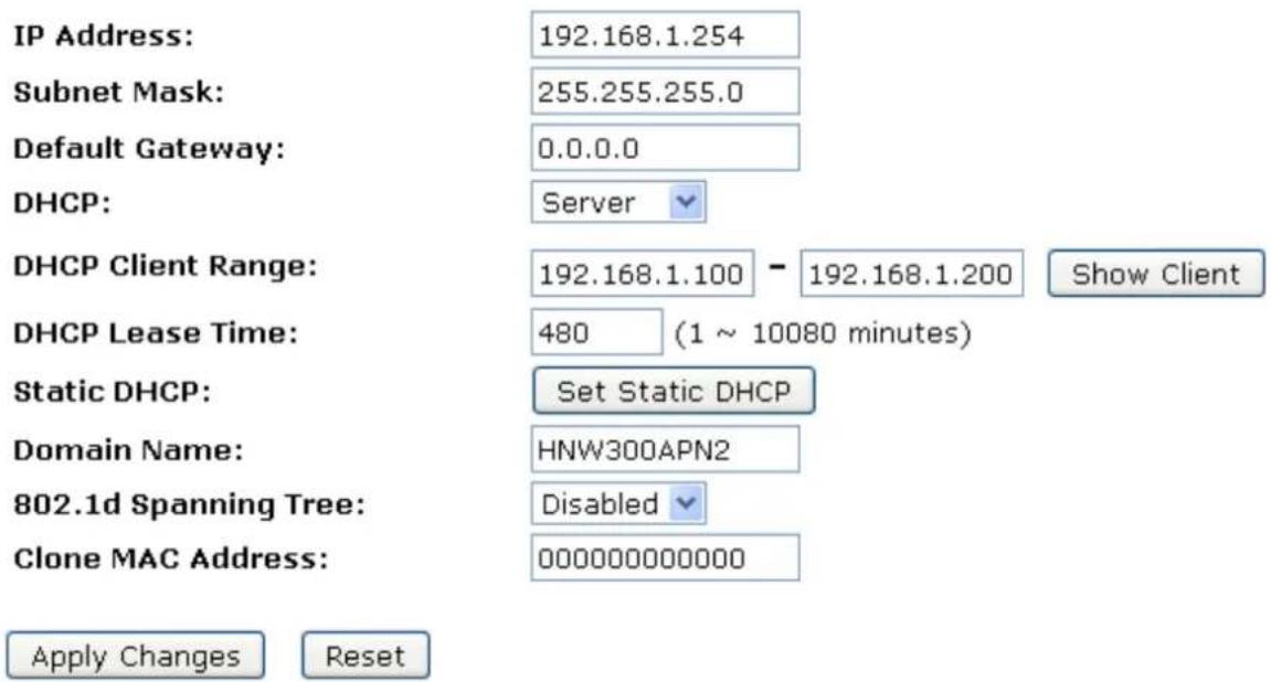
- Type IP Address and Change default LAN port IP address.
- Click in the IP Address and Subnet Mask box and type a new IP Address and Subnet Mask.
- Change the default DHCP Client Range.
- Click Apply Changes.
LAN Interface Setup
This page is used to configure the parameters for local area network which connects to the LAN port of your Access Point. Here you may change the setting for IP address, subnet mask, DHCP, etc..
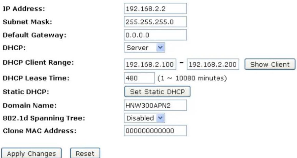
- Change setting successfully.
Change setting successfully!
Do not turn off or reboot the Device during this time.
Please wait 17 seconds ...
You may also need to renew your DHCP lease:
Windows 95/98
a. Select Run... from the Start menu.
b. Enter winipcfg and click OK.
c. Select your ethernet adaptor from the pull-down menu
d. Click Release All and then Renew All.
e. Exit the winipcfg dialog.
Windows NT/Windows 2000/Windows XP
a. Bring up a command window.
b. Type ipconfig /release in the command window.
c. Type ipconfig /renew.
d. Type exit to close the command window.
Linux
a. Bring up a shell.
b. Type pump -r to release the lease.
c. Type pump to renew the lease.
Note: If you change the LAN IP address of the device while connected through your Web browser, you will be disconnected. You must open a new connection by entering your new LAN IP address as the URL.
11.3 Show Client
To the IP Address, MAC Address, and Expired Time of the DHCP lease for each client computer/device:
- From the left-hand Network Settings -> LAN Interface menu. The following page is displayed:
LAN Interface Setup
This page is used to configure the parameters for local area network which connects to the LAN port of your Access Point. Here you may change the setting for IP address, subnet mask, DHCP, etc..
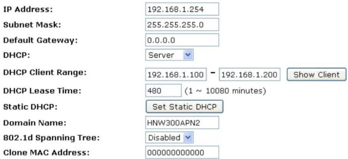
Apply Changes
Reset
- Click on Show Client button. The following page is displayed:
Active DHCP Client Table
This table shows the assigned IP address, MAC address and time expired for each DHCP leased client.
| IP Address | MAC Address | Time Expired(s) |
| 192.168.1.100 | 00:24: 1d: 1d: cf: cd | 19580 |
Refresh
Close
12. WAN Interface
This chapter describes how to configure the way that your device connects to the Internet. Your ISP determines what type of Internet access you should use and provides you with any information that you need in order to configure the Internet access to your device.
Wireless Gateway supports five methods of obtaining the WAN IP address:
| Option | Description |
| Static IP | Choose this option if you are a leased line user with a fixed IP address. |
| DHCP Client | Choose this option if you are connected to the Internet through a Cable modem line. |
| PPPoE | Choose this option if you are connected to the Internet through a DSL line |
| PPTP | Choose this option if you are connected to the PPTP Server |
| L2TP | Choose this option if you are connected to the L2TP Server |
- From the left-hand Network Settings -> WAN Interface menu. The following page is displayed:
WAN Interface Setup
This page is used to configure the parameters for Internet network which connects to the WAN port of your Access Point. Here you may change the access method to static IP, DHCP, PPPoE, PPTP or L2TP by click the item value of WAN Access type.
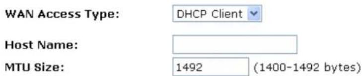
Attain DNS Automatically
○ Set DNS Manually
DNS 1:
DNS 2:
DNS 3:
Clone MAC Address:
Enable uPNP
Enable IGMP Proxy
Enable Ping Access on WAN
□ Enable Web Server Access on WAN
√ Enable IPsec pass through on VPN connection
√ Enable PPTP pass through on VPN connection
√ Enable L2TP pass through on VPN connection
Enable IPv6 pass through on VPN connection
Apply Changes
Reset
| Option | Description | |
| WAN Access Type | Static IP | Choose this option if you are a leased line user with a fixed address. |
| DHCP Client | Choose this option if you are connected to the Internet through a Cable modem line. | |
| PPPoE | Choose this option if you are connected to the Internet through a DSL line | |
| PPTP | Choose this option if you are connected to the PPTP Serve | |
| L2TP | Choose this option if you are connected to the L2TP Serve | |
| Host Name | The name of the DHCP host | |
| IP Address | Check with your ISP provider | |
| Subnet Mask | Check with your ISP provider | |
| Default Gateway | Check with your ISP provider | |
| User Name | User name for PPPoE registration recognized by the Internet service provider | |
| Password | Password for PPPoE registration recognized by the Internet service provider | |
| Service Name | Service Name for PPPoE registration recognized by the Internet service provider | |
| Connection Type | Continuous | The connection is always on |
| Connect on Demand | Enter the minutes after which the session must be disconnected, if no activity takes place | |
| Manual | Manually connect | |
| Idle Time | Enter the minutes after which the session must be disconnected | |
| WAN Physical | Dynamic IP or Static IP for PPP Connection | |
| MTU Size | Specify the network MTU rate | |
| Attain DNS Automatically | Obtain DNS server address automatically | |
| DNS 1 (Primary DNS Server) | Check with your ISP provider | |
| DNS 2 (Secondary DNS Server) | Check with your ISP provider | |
| DNS 3 (Third DNS Server) | Check with your ISP provider | |
| Clone MAC Address | Clone MAC lets the device identify itself as another compute or device | |
| Enable uPNP | Enable or Disable uPNP | |
| Enable IGMP Proxy | Enable or Disable IGMP Proxy | |
| Enable Ping Access on WAN | Enable or Disable Ping Access on WAN | |
| Enable Web Server Access on WAN | Enable or Disable Web Server Access on WAN | |
| Enable IPsec pass through on VPN connection | Enable or Disable IPsec pass through on VPN connection | |
| Enable PPTP pass through on VPN connection | Enable or Disable PPTP pass through on VPN connection | |
| Enable L2TP pass through on VPN connection | Enable or Disable L2TP pass through on VPN connection | |
12.1 Configuring Static IP connection
If you are a leased line user with a fixed IP address, enter in the IP address, subnet mask, gateway address, and DNS (domain name server) address(es) provided to you by your ISP.
If your ISP wants you to connect to the Internet using Static IP, follow the instructions below.
- From the left-hand Network Settings -> WAN Interface menu. The following page is displayed:
- From the WAN Access Type drop-down list, select Static IP setting.
- Enter WAN IP Address, WAN Subnet Mask, Default Gateway and DNS which was given by Telecom or by your Internet Service Provider (ISP).
- Click Apply Changes.
WAN Interface Setup
This page is used to configure the parameters for Internet network which connects to the WAN port of your Access Point. Here you may change the access method to static IP, DHCP, PPPoE, PPTP or L2TP by click the item value of WAN Access type.
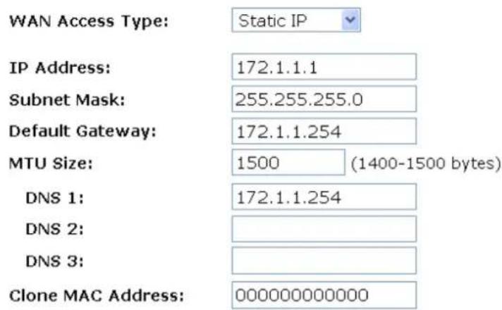
Enable uPNP
Enable IGMP Proxy
Enable Ping Access on WAN
□ Enable Web Server Access on WAN
Enable IPsec pass through on VPN connection
√ Enable PPTP pass through on VPN connection
√ Enable L2TP pass through on VPN connection
☐ Enable IPv6 pass through on VPN connection
Apply Changes Reset
- Change setting successfully! Click on Reboot Now button to confirm.
Change setting successfully!
Your changes have been saved. The router must be rebooted for the changes to take effect. You can reboot now, or you can continue to make other changes and reboot later.
Reboot Now Reboot Later
12.2 Configuring DHCP Client connection
Dynamic Host Configuration Protocol (DHCP), Dynamic IP (Get WAN IP Address automatically). If you are connected to the Internet through a Cable modem line, then a dynamic IP will be assigned.
If your ISP wants you to connect to the Internet using DHCP Client, follow the instructions below.
- From the left-hand Network Settings -> WAN Interface menu. The following page is displayed:
- From the WAN Access Type drop-down list, select DHCP Client setting.
- Click Apply Changes.
WAN Interface Setup
This page is used to configure the parameters for Internet network which connects to the WAN port of your Access Point. Here you may change the access method to static IP, DHCP, PPPoE, PPTP or L2TP by click the item value of WAN Access type.
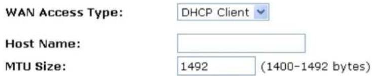
Attain DNS Automatically
○ Set DNS Manually
DNS 1:
DNS 2:
DNS 3:
Clone MAC Address:
Enable uPNP
Enable IGMP Proxy
Enable Ping Access on WAN
Enable Web Server Access on WAN
√ Enable IPsec pass through on VPN connection
√ Enable PPTP pass through on VPN connection
Enable L2TP pass through on VPN connection
☐ Enable IPv6 pass through on VPN connection
Apply Changes
Reset
- Change setting successfully! Click on Reboot Now button to confirm.
Change setting successfully!
Your changes have been saved. The router must be rebooted for the changes to take effect. You can reboot now, or you can continue to make other changes and reboot later.
Reboot Now
Reboot Later
12.3 Configuring PPPoE connection
If your ISP's Internet service uses PPPoE you need to set up a PPP login account. The first time that you login to the Internet, your ISP will ask you to enter a username and password so they can check that you are a legitimate, registered Internet service user. Your device stores these authentication details, so you will not have to enter this username and password every time you login.
If your ISP wants you to connect to the Internet using PPP, follow the instructions below.
- From the left-hand Network Settings -> WAN Interface menu. The following page is displayed:
- From the WAN Access Type drop-down list, select PPPoE setting.
- Enter User Name/Password provided by your ISP. Type them in the relevant boxes.
- Click Apply Changes.
WAN Interface Setup
This page is used to configure the parameters for Internet network which connects to the WAN port of your Access Point. Here you may change the access method to static IP, DHCP, PPPoE, PPTP or L2TP by click the item value of WAN Access type.
WAN Access Type:
PPPoE
User Name:
Password:
Service Name(AC):
Connection Type:
Continuous
Connect Disconnect
Idle Time:
5 (1-1000 minutes) 1452 (1360-1492 bytes)
MTU Size:
Attain DNS Automatically
○ Set DNS Manually
DNS 1:
DNS 2:
DNS 3:
Clone MAC Address:
Enable uPNP
Enable IGMP Proxy
□ Enable Ping Access on WAN
□ Enable Web Server Access on WAN
√ Enable IPsec pass through on VPN connection
√ Enable PPTP pass through on VPN connection
√ Enable L2TP pass through on VPN connection
☐ Enable IPv6 pass through on VPN connection
Apply Changes
Reset
- Change setting successfully! Click on Reboot Now button to confirm.
12.4 Configuring PPTP connection
If your ISP/Network Administrator wants you to connect to the Internet using PPTP, follow the instructions below.
- From the left-hand Network Settings -> WAN Interface menu. The following page is displayed:
- From the WAN Access Type drop-down list, select PPTP setting.
- Enter IP Address/Subnet Mask/Server IP Address/User Name/Password provided by your ISP. Type them in the relevant boxes.
WAN Interface Setup
This page is used to configure the parameters for Internet network which connects to the WAN port of your Access Point. Here you may change the access method to static IP, DHCP, PPPoE, PPTP or L2TP by click the item value of WAN Access type.
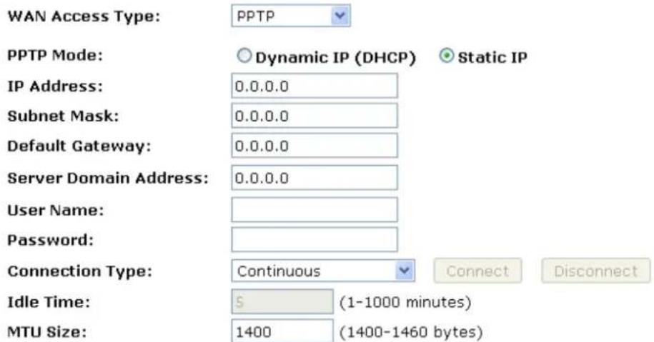
☐ Request MPPE Encryption ☐ Request MPPC Compression
Attain DNS Automatically
Set DNS Manually
DNS 1:
DNS 2:
DNS 3:
Clone MAC Address:
Enable uPNP
Enable IGMP Proxy
□ Enable Ping Access on WAN
Enable Web Server Access on WAN
√ Enable IPsec pass through on VPN connection
√ Enable PPTP pass through on VPN connection
√ Enable L2TP pass through on VPN connection
□ Enable IPv6 pass through on VPN connection
Apply Changes Reset
- Click Apply Changes
- Change setting successfully! Click on Reboot Now button to confirm.
12.5 Configuring L2TP connection
If your ISP/Network Administrator wants you to connect to the Internet using L2TP, follow the instructions below.
- From the left-hand Network Settings -> WAN Interface menu. The following page is displayed:
- From the WAN Access Type drop-down list, select L2TP setting.
- Enter IP Address/Subnet Mask/Server IP Address/User Name/Password provided by your ISP. Type them in the relevant boxes.
WAN Interface Setup
This page is used to configure the parameters for Internet network which connects to the WAN port of your Access Point. Here you may change the access method to static IP, DHCP, PPPoE, PPTP or L2TP by click the item value of WAN Access type.
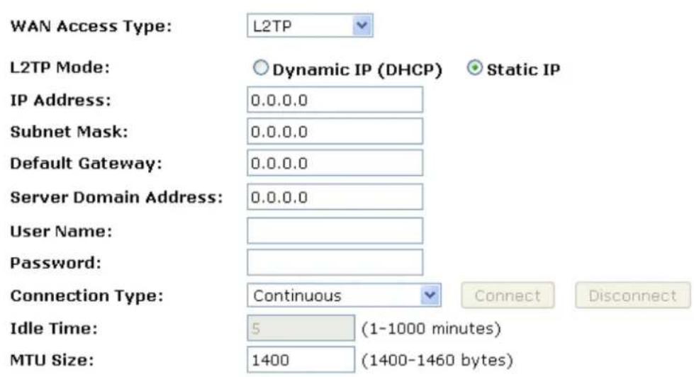
Attain DNS Automatically
Set DNS Manually
DNS 1:
DNS 2:
DNS 3:
Clone MAC Address:
Enable uPNP
Enable IGMP Proxy
□ Enable Ping Access on WAN
□ Enable Web Server Access on WAN
√ Enable IPsec pass through on VPN connection
√ Enable PPTP pass through on VPN connection
√ Enable L2TP pass through on VPN connection
□ Enable IPv6 pass through on VPN connection
Apply Changes
Reset
- Click Apply Changes.
- Change setting successfully! Click on Reboot Now button to confirm.
12.6 Clone MAC Address
Some particularly ISPs do not want you to have a home network and have a DSL/Cable modem that allows only 1 MAC to talk on the internet. If you change network cards, you have to call them up to change the MAC. The Wireless Gateway can it's MAC to computer's one that was originally set up for such an ISP.
This page allows you to enable or disable Clone MAC Address option.
- From the left-hand Network Settings -> WAN Interface menu. The following page is displayed:
- Enter the MAC for example 0123456789ab that you want to be instead of in the Clone MAC Address field.
- If you enter 12 digits of 0 in the Clone MAC Address field, it'll disable Clone MAC Address function.
WAN Interface Setup
This page is used to configure the parameters for Internet network which connects to the WAN port of your Access Point. Here you may change the access method to static IP, DHCP, PPPoE, PPTP or L2TP by click the item value of WAN Access type.
WAN Access Type:
DHCP Client
Host Name:

MTU Size:
1492 (1400-1492 bytes)
Attain DNS Automatically
Set DNS Manually
DNS 1:
DNS 2:
DNS 3:
Clone MAC Address:
0123456789ab
Enable uPNP
Enable IGMP Proxy
Enable Ping Access on WAN
Enable Web Server Access on WAN
√ Enable IPsec pass through on VPN connection
√ Enable PPTP pass through on VPN connection
√ Enable L2TP pass through on VPN connection
Enable IPv6 pass through on VPN connection
Apply Changes
Reset
- Click Apply Changes.
- Change setting successfully! Click on Reboot Now button to confirm.
13. Port Filtering
Entries in Current Filter Table are used to restrict certain ports and types of data packets from your local network to Internet through the Gateway. Use of such filters can be helpful in securing or restricting your local network.
- From the left-hand Firewall -> Port Filtering menu. The following page is displayed:
Port Filtering
Entries in this table are used to restrict certain types of data packets from your local network to Internet through the Gateway. Use of such filters can be helpful in securing or restricting your local network.

Current Filter Table:

| Option | Description |
| Enable Port Filtering | Enable/Disable the WAN packet filter.Default setting is Disable. |
| Port Range | Enter the port range to be filtered for both Outbound and Inbound packet |
| Protocol | Select the Protocol to be filtered for both Outbound and Inbound packetBoth: To filter both TCP and UDP protocolTCP: To filter only TCP protocolUDP: filter only UDP protocol |
| Comment | Fill in the note for manager what the purpose of certain port filtering rule |
| Current Filter Table | The Port Filters that was created is listed here |
Note: You must ensure that the single port or range specified does not overlap with a port or range for an existing common or custom application.
13.1 Port filtering for TCP port 80
Please follow example below to deny the TCP port 80 for both Outbound and Inbound packet.
- From the left-hand Firewall -> Port Filtering menu. The following page is displayed:
Port Filtering
Entries in this table are used to restrict certain types of data packets from your local network to Internet through the Gateway. Use of such filters can be helpful in securing or restricting your local network.

Current Filter Table:

- Check the option Enable Port Filtering to enable the port filtering.
- Enter 80 and 80 in Port Range field.
- From the Protocol drop-down list, select TCP setting.
- Enter HTTP in Comment field.
- Click Apply Changes.

- Now the port filter that you created has been added and listed in the Current Filter Table.
- Now the TCP port for both Outbound and Inbound packet has been denied.
Current Filter Table:
| Port Range | Protocol | Comment | Select |
| 80 | TCP | HTTP |
Now you cannot visit any web site due to the TCP port 80 has been blocked by the Port Filtering rule that created.
13.2 Port filtering for UDP port 53
Please follow example below to deny the UDP port 53 for both Outbound and Inbound packet.
- From the left-hand Firewall -> Port Filtering menu. The following page is displayed:
Port Filtering
Entries in this table are used to restrict certain types of data packets from your local network to Internet through the Gateway. Use of such filters can be helpful in securing or restricting your local network.

Current Filter Table:

- Check the option Enable Port Filtering to enable the port filtering.
- Enter 53 and 53 in Port Range field.
- From the Protocol drop-down list, select UDP setting.
- Enter DNS Resolve in Comment field.
- Click Apply Changes.

- Now the port filter that you created has been added and listed in the Current Filter Table.
- Now the UDP port 53 for both Outbound and Inbound packet has been denied.
Current Filter Table:
| Port Range | Protocol | Comment | Select |
| 53 | UDP | DNS Resolve |
Now you cannot visit any web site by domain due to the UDP port 53 has been blocked by the Port Filtering rule that created.
You can enter the IP Address of that web site to visit.
14. IP Filtering
Entries in this table are used to restrict certain types of data packets from your local network to Internet through the Gateway. Use of such filters can be helpful in securing or restricting your local network.
The IP filter feature enables you to create rules that control the forwarding of incoming and outgoing data between the LAN and WAN side.
You can create IP filter rules to block attempts by certain computers on your LAN to access certain types of data or Internet locations. You can also block accesses to your LAN computers from the WAN side.
When you define an IP filter rule and enable the feature, you instruct the ADSL/Ethernet router to examine data packets to determine whether they meet criteria set forth in the rule. The criteria can include the network or internet protocol, the packet carries the direction in which it is traveling (for example, from the LAN to the WAN and vice versa).
If the packet matches the criteria established in a rule, the packet can either be accepted (forwarded towards its destination), or denied (discarded), depending on the action specified in the rule.
The IP Filter Configuration page provides the capability to enable/disable the IP filter feature and the IP Filter rule entries for all currently established rules.
- From the left-hand Firewall -> IP Filtering menu. The following page is displayed:
IP Filtering
Entries in this table are used to restrict certain types of data packets from your local network to Internet through the Gateway. Use of such filters can be helpful in securing or restricting your local network.

Current Filter Table:

14.1 IP filtering for TCP with specified IP
Please follow example below to deny the TCP protocol for specified IP.
- From the left-hand Firewall -> IP Filtering menu. The following page is displayed:
IP Filtering
Entries in this table are used to restrict certain types of data packets from your local network to Internet through the Gateway. Use of such filters can be helpful in securing or restricting your local network.

Current Filter Table:

- Check the option Enable IP Filtering to enable the IP Filtering.
- Enter the IP Address that you want to be denied in Loal IP Address field.
- From the Protocol drop-down list, select TCP setting.
- Enter any comment in Comment field.
- Click Apply Changes.

Current Filter Table:

- Now the IP Filter that you created has been added and listed in the Current Filter Table.
- Now the TCP protocol for both Outbound and Inbound packet has been denied.
Current Filter Table:
| Local IP Address | Protocol | Comment | Select |
| 10.0.0.102 | TCP | Deny TCP | |
| Delete Selected Delete All Reset | |||
Now The Local IP Address for example 10.0.0.102 that listed in the Current Filter Table cannot visit any application that use TCP protocol for example web site due to the Protocol TCP has been blocked by the IP Filtering rule that created.
14.2 IP filtering for UDP with specified IP
Please follow example below to deny the UDP protocol for specified IP.
- From the left-hand Firewall -> IP Filtering menu. The following page is displayed:
IP Filtering
Entries in this table are used to restrict certain types of data packets from your local network to Internet through the Gateway. Use of such filters can be helpful in securing or restricting your local network.

Current Filter Table:
| Local IP Address | Protocol | Comment | Select |
| Delete Selected | Delete All | Reset |
- Check the option Enable IP Filtering to enable the IP Filtering.
- Enter the IP Address that you want to be denied in Loal IP Address field.
- From the Protocol drop-down list, select UDP setting.
- Enter any comment in Comment field.
- Click Apply Changes.

Current Filter Table:
| Local IP Address | Protocol | Comment | Select |
| Delete Selected | Delete All | Reset |
- Now the IP Filter that you created has been added and listed in the Current Filter Table.
- Now the UDP protocol for both Outbound and Inbound packet has been denied.
Current Filter Table:
| Local IP Address | Protocol | Comment | Select |
| 10.0.0.102 | UDP | Deny UDP |
Now The Local IP Address for example 10.0.0.102 that listed in the Current Filter Table cannot visit any application that use UDP protocol for example TFTP Service due to the Protocol UDP has been blocked by the IP Filtering rule that created.
14.3 IP filtering for both TCP and UDP with specified IP
Please follow example below to deny the both TCP and UDP protocol for specified IP.
- From the left-hand Firewall -> IP Filtering menu. The following page is displayed:
IP Filtering
Entries in this table are used to restrict certain types of data packets from your local network to Internet through the Gateway. Use of such filters can be helpful in securing or restricting your local network.

Current Filter Table:
| Local IP Address | Protocol | Comment | Select |
| Delete Selected | Delete All | Reset |
- Check the option Enable IP Filtering to enable the IP Filtering.
- Enter the IP Address that you want to be denied in Loal IP Address field.
- From the Protocol drop-down list, select Both setting.
- Enter any comment in Comment field.
- Click Apply Changes.

Current Filter Table:
| Local IP Address | Protocol | Comment | Select |
| Delete Selected | Delete All | Reset |
- Now the IP Filter that you created has been added and listed in the Current Filter Table.
- Now the TCP and UDP protocol for both Outbound and Inbound packet has been denied.
Current Filter Table:
| Local IP Address | Protocol | Comment | Select |
| 10.0.0.102 | TCP+UDP | Deny TCP+UDP |
15. MAC Filtering
Entries in this table are used to restrict certain types of data packets from your local network to Internet through the Wireless Gateway. Use of such filters can be helpful in securing or restricting your local network.
- From the left-hand Firewall -> MAC Filtering menu. The following page is displayed:
MAC Filtering
Entries in this table are used to restrict certain types of data packets from your local network to Internet through the Gateway. Use of such filters can be helpful in securing or restricting your local network.

Current Filter Table:

15.1 MAC filtering for specified MAC Address
Please follow example below to deny the specified MAC Address has the Internet Access.
- From the left-hand Firewall -> MAC Filtering menu. The following page is displayed:
MAC Filtering
Entries in this table are used to restrict certain types of data packets from your local network to Internet through the Gateway. Use of such filters can be helpful in securing or restricting your local network.

Current Filter Table:

flowchart
graph LR
    A["Delete Selected"] --> B["Delete All"]
    B --> C["Reset"]
    C --> D["Comment"]
    D --> E["Select"]
- Check the option Enable MAC Filtering to enable the MAC Filtering.
- Enter the MAC Address that you want to be denied in MAC Address field.
- Enter any comment in Comment field.
- Click Apply Changes.

Current Filter Table:

- Now the MAC Filter that you created has been added and listed in the Current Filter Table.
- Now the MAC Address in the Current Filter Table cannot have the Internet Access.
Current Filter Table:
| MAC Address | Comment | Select |
| 00:0a:48:12:29:26 | Test | |
| Delete Selected Delete All Reset |
16. Port Forwarding
Entries in this table allow you to automatically redirect common network services to a specific machine behind the NAT firewall. These settings are only necessary if you wish to host some sort of server like a web server or mail server on the private local network behind your Gateway's NAT firewall.
Your device has built in advanced Security features that protect your network by blocking unwanted traffic from the Internet.
If you simply want to connect from your local network to the Internet, you do not need to make any changes to the default Security configuration. You only need to edit the configuration if you wish to do one or both of the following:
- allow Internet users to browse the user pages on your local network (for example, by providing an FTP or HTTP server)
- play certain games which require accessibility from the Internet
This chapter describes how to configure Security to suit the needs of your network.
By default, the IP addresses of your LAN PCs are hidden from the Internet. All data sent from your LAN PCs to a PC on the Internet appears to come from the IP address of your device.
In this way, details about your LAN PCs remain private. This security feature is called Port Forwarding.
- From the left-hand Firewall -> Port Forwarding menu. The following page is displayed:
Port Forwarding
Entries in this table allow you to automatically redirect common network services to a specific machine behind the NAT firewall. These settings are only necessary if you wish to host some sort of server like a web server or mail server on the private local network behind your Gateway's NAT firewall.

Current Port Forwarding Table:

16.1 Port Forwarding for TCP with specified IP
Please follow example below to configure the Port Forwarding to Specified IP with TCP.
- From the left-hand Firewall -> Port Forwarding menu. The following page is displayed:
Port Forwarding
Entries in this table allow you to automatically redirect common network services to a specific machine behind the NAT firewall. These settings are only necessary if you wish to host some sort of server like a web server or mail server on the private local network behind your Gateway's NAT firewall.

Current Port Forwarding Table:
| Local IP Address | Protocol | Port Range | Comment | Select |
| Delete Selected Delete All Reset | ||||
- Check the option Enable Port Forwarding to enable the Enable Port Forwarding.
- Enter the IP Address that the port you want to be forwarded in IP Address field.
- From the Protocol drop-down list, select TCP setting.
- Enter any comment in Comment field.
- Click Apply Changes.
Port Forwarding
Entries in this table allow you to automatically redirect common network services to a specific machine behind the NAT firewall. These settings are only necessary if you wish to host some sort of server like a web server or mail server on the private local network behind your Gateway's NAT firewall.
Enable Port Forwarding
IP Address: 10.0.0.101 Protocol: TCP▼ Port Range: 80 - 80 Comment: Test
Apply Changes Reset
Current Port Forwarding Table:

- Now the IP Address and port range that you created has been added and listed in the Current Filter Table.
- Now the port range of the IP Address in the Current Filter Table can be access from Internet by TCP protocol.
Current Port Forwarding Table:
| Local IP Address | Protocol | Port Range | Comment | Select |
| 10.0.0.101 | TCP | 80 | Test |
16.2 Port Forwarding for UDP with specified IP
Please follow example below to configure the Port Forwarding to Specified IP with UDP.
- From the left-hand Firewall -> Port Forwarding menu. The following page is displayed:
Port Forwarding
Entries in this table allow you to automatically redirect common network services to a specific machine behind the NAT firewall. These settings are only necessary if you wish to host some sort of server like a web server or mail server on the private local network behind your Gateway's NAT firewall.

Current Port Forwarding Table:
| Local IP Address | Protocol | Port Range | Comment | Select |
| Delete Selected | Delete All | Reset |
- Check the option Enable Port Forwarding to enable the Enable Port Forwarding.
- Enter the IP Address that the port you want to be forwarded in IP Address field.
- From the Protocol drop-down list, select UDP setting.
- Enter any comment in Comment field.
- Click Apply Changes.
Port Forwarding
Entries in this table allow you to automatically redirect common network services to a specific machine behind the NAT firewall. These settings are only necessary if you wish to host some sort of server like a web server or mail server on the private local network behind your Gateway's NAT firewall.

Current Port Forwarding Table:
| Local IP Address | Protocol | Port Range | Comment | Select |
| Delete Selected Delete All Reset | ||||
- Now the IP Address and port range that you created has been added and listed in the Current Filter Table.
- Now the port range of the IP Address in the Current Filter Table can be access from Internet by UDP protocol.
Current Port Forwarding Table:
| Local IP Address | Protocol | Port Range | Comment | Select |
| 10.0.0.101 | UDP | 69 | Test |
17. URL Filtering
URL filter is used to deny LAN users from accessing the internet. Block those URLs which contain keywords listed below.
- From the left-hand Firewall -> URL Filtering menu. The following page is displayed:
URL Filtering
URL filter is used to deny LAN users from accessing the internet. Block those URLs which contain keywords listed below.
Enable URL Filtering
- deny url address(black list)
○ allow url address(white list)
URL Address:
Apply Changes
Reset
Current Filter Table:
URL Address
Select
Delete Selected
Delete All
Reset
17.1 URL filtering for specified URL Address
Please follow example below to deny LAN users from accessing the Internet.
- From the left-hand Firewall -> URL Filtering menu. The following page is displayed:
URL Filtering
URL filter is used to deny LAN users from accessing the internet. Block those URLs which contain keywords listed below.
Enable URL Filtering
- deny url address(black list)
○ allow url address(white list)
URL Address:
Apply Changes Reset
Current Filter Table:

- Check the option Enable URL Filtering to enable the URL Filtering.
- Check the option deny url address(black list) to deny url address(black list).
- Enter the URL Address that you want to be denied for LAN user.
- Click Apply Changes.
URL Filtering
URL filter is used to deny LAN users from accessing the internet. Block those URLs which contain keywords listed below.
Enable URL Filtering
deny url address(black list)
○ allow url address(white list)
URL Address: www.google.com
Apply Changes Reset
- Now the URL Filter that you created has been added and listed in the Current Filter Table.
- Now the URL Address in the Current Filter Table cannot be visited.
Current Filter Table:
| URL Address | Select |
| www.google.com | |
| Delete Selected Delete All Reset | |
18. DMZ
A Demilitarized Zone is used to provide Internet services without sacrificing unauthorized access to its local private network. Typically, the DMZ host contains devices accessible to Internet traffic, such as Web (HTTP) servers, FTP servers, SMTP (e-mail) servers and DNS servers.
- From the left-hand Firewall -> DMZ menu. The following page is displayed:
DMZ
A Demilitarized Zone is used to provide Internet services without sacrificing unauthorized access to its local private network. Typically, the DMZ host contains devices accessible to Internet traffic, such as Web (HTTP) servers, FTP servers, SMTP (e-mail) servers and DNS servers.
Enable DMZ
DMZ Host IP Address:
Apply Changes
Reset
18.1 DMZ Host IP Address
Please follow example below to configure the DMZ to Host IP Address.
- From the left-hand Firewall -> DMZ menu. The following page is displayed:
DMZ
A Demilitarized Zone is used to provide Internet services without sacrificing unauthorized access to its local private network. Typically, the DMZ host contains devices accessible to Internet traffic, such as Web (HTTP) servers, FTP servers, SMTP (e-mail) servers and DNS servers.
Enable DMZ
DMZ Host IP Address:
Apply Changes
Reset
- Check the option Enable DMZ to enable the Enable DMZ.
- Enter the IP Address that to be the DMZ Host in DMZ Host IP Address field.
- Click Apply Changes.
DMZ
A Demilitarized Zone is used to provide Internet services without sacrificing unauthorized access to its local private network. Typically, the DMZ host contains devices accessible to Internet traffic, such as Web (HTTP) servers, FTP servers, SMTP (e-mail) servers and DNS servers.
Enable DMZ
DMZ Host IP Address: 10.0.0.101
Apply Changes
Reset
19. VLAN
Entries in below table are used to config VLAN settings. VLANs are created to provide the segmentation services traditionally provided by routers. VLANs address issues such as scalability, security, and network management.
- From the left-hand Firewall -> VLAN menu. The following page is displayed:
VLAN Settings
Entries in below table are used to config vlan settings. VLANs are created to provide the segmentation services traditionally provided by routers. VLANs address issues such as scalability, security, and network management.
Enable VLAN
| Enable | Ethernet/Wireless | WAN/LAN | Tag | VID (1~4090) | Priority | CFI |
| Ethernet Port1 | LAN | 3022 | 7 | √ | ||
| Ethernet Port2 | LAN | 3030 | 0 | √ | ||
| Ethernet Port3 | LAN | 500 | 3 | √ | ||
| Ethernet Port4 | LAN | 1 | 0 | √ | ||
| Wireless Primary AP | LAN | 1 | 0 | √ | ||
| Virtual AP1 | LAN | 1 | 0 | √ | ||
| Virtual AP2 | LAN | 1 | 0 | √ | ||
| Virtual AP3 | LAN | 1 | 0 | √ | ||
| Virtual AP4 | LAN | 1 | 0 | √ | ||
| Ethernet Port5 | WAN | 1 | 0 | √ |
Apply Changes
Reset
20. QoS
Entries in this table improve your online gaming experience by ensuring that your game traffic is prioritized over other network traffic, such as FTP or Web.
- From the left-hand Firewall -> QoS menu. The following page is displayed:
QoS
Entries in this table improve your online gaming experience by ensuring that your game traffic is prioritized over other network traffic, such as FTP or Web.
Enable QoS
√ Automatic Uplink Speed
Manual Uplink Speed (Kbps):
512
√ Automatic Downlink Speed
Manual Downlink Speed (Kbps):
512
QoS Rule Setting:
Address Type:
Local IP Address:
MAC Address:
Mode:
Uplink Bandwidth (Kbps):
Downlink Bandwidth (Kbps):
Comment:
Apply Changes
Reset
IP
MAC
Current QoS Rules Table:

21. Route Setup
This page is used to setup dynamic routing protocol or edit static route entry.
- From the left-hand Route Setup menu. The following page is displayed:
Routing Setup
This page is used to setup dynamic routing protocol or edit static route entry.
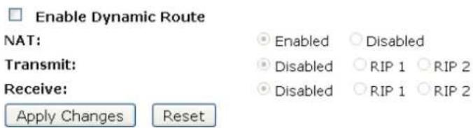
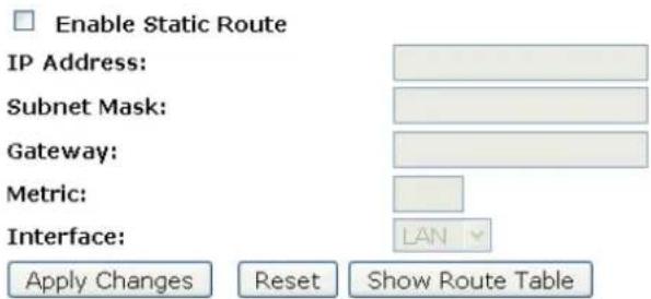
Static Route Table:
| Destination IP Address | Netmask | Gateway | Metric | Interface | Select |
| Delete Selected | Delete All | Reset |
22. Status
This page displays the current information for the device. It will display the LAN, WAN, and system firmware information. This page will display different information, according to WAN setting (Static IP, DHCP, or PPPoE).
- From the left-hand Management -> Status menu. The following page is displayed:
Status
This page shows the current status and some basic settings of the device.
| System | |
| Uptime | 0day:0h:8m:41s |
| Firmware Version | v3.2.5 |
| Customer Version | REAN_E_v325_2T2R_CAR_01_131014 |
| Build Time | Mon Oct 14 04:23:11 EDT 2013 |
| Wireless Configuration | |
| Mode | AP |
| Band | 2.4 GHz (B+G+N) |
| SSID | Hamlet |
| Channel Number | 11 |
| Encryption | Disabled |
| BSSID | 00:13:33:00:00:21 |
| Associated Clients | 0 |
| TCP/IP Configuration | |
| Attain IP Protocol | Fixed IP |
| IP Address | 192.168.1.254 |
| Subnet Mask | 255.255.255.0 |
| Default Gateway | 192.168.1.254 |
| DHCP Server | Enabled |
| MAC Address | 00:13:33:00:00:1f |
| WAN Configuration | |
| Attain IP Protocol | Getting IP from DHCP server... |
| IP Address | 0.0.0.0 |
| Subnet Mask | 0.0.0.0 |
| Default Gateway | 0.0.0.0 |
| MAC Address | 00:13:33:00:00:20 |
23. Statistics
This page shows the packet counters for transmission and reception regarding to wireless and Ethernet networks.
- From the left-hand Management -> Statistics menu. The following page is displayed:
Statistics
This page shows the packet counters for transmission and reception regarding to wireless and Ethernet networks.
| Wireless LAN | Sent Packets | 135 |
| Received Packets | 31439 | |
| Ethernet LAN | Sent Packets | 5748 |
| Received Packets | 5560 | |
| Ethernet WAN | Sent Packets | 1840 |
| Received Packets | 4385 |
Refresh
24. Dynamic DNS
When you want your internal server to be accessed by using DNS name rather than using the dynamic IP address, you can use the DDNS service. The DDNS server allows to alias a dynamic IP address to a static hostname.
This chapter provides you an overview of the Dynamic DNS feature of the modem and configuration details related to it.
Overview
If some host has a dynamic IP address that keeps changing frequently, it is difficult to keep updating the IP record that is associated with the domain name of this host in the zone files. This will result in non-accessibility of this host on the Internet. Dynamic DNS service allows to keep mapping of a dynamic IP address of such host to a static hostname. Dynamic DNS services are provided by many websites. The host needs to register with some website and get a domain name. When the IP address of the host changes, it just needs to send a message to the website that's providing dynamic DNS service to this host. For this to work, an automated update client needs to be implemented. These update clients send update messages to the servers whenever there is some change in the IP address of that host. Then, the server updates the entries for that host and replies back with some return code.
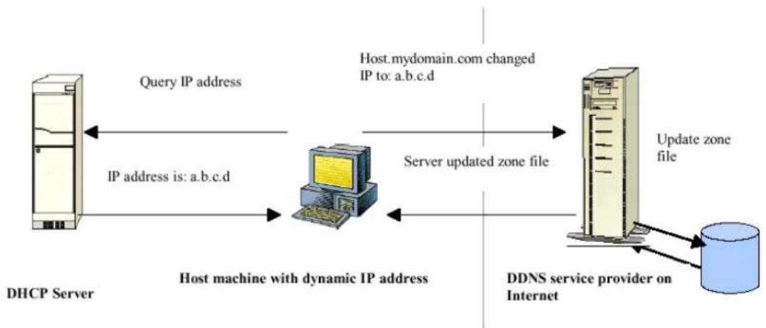
flowchart
graph LR
    A["DHCP Server"] -->|Query IP address| B["Host machine with dynamic IP address"]
    B -->|IP address is: a.b.c.d| A
    B -->|Server updated zone file| C["DDNS service provider on Internet"]
    C -->|Update zone file| D["DBD"]
    style A fill:#f9f,stroke:#333
    style B fill:#ccf,stroke:#333
    style C fill:#cfc,stroke:#333
    style D fill:#fcc,stroke:#333
Above Figure explains one such scenario in which a host gets a dynamic IP address for itself from a DHCP server. As the host has registered with one of the dynamic DNS service providers on the Internet, it sends an update message to the service provider with host name and changed IP address. The service provider updates the new IP address of the host in the zone files that have entry for that host name and replies back with some return code. The return code communicates the success or failure of the update message. This process is repeated every time the host's IP address changes.
If the dynamic DNS service provider is notified of the same IP address again and again, then it considers it an abuse and might block the host name. To avoid this scenario, the IP address that was successfully updated to the ISP is stored on the unit. Whenever we receive an IP address change notification, the new IP address is compared with the IP address that was stored on the last update. If they differ, then only an update request is sent. However, when the system comes up there is no way of knowing what was the IP address on last successful update before the system went down. You need to give the command "system config save" periodically to save this IP address on Flash.
Registering With Dynamic DNS Service Provider
Currently, Wireless Gateway supports two Dynamic DNS service providers, www.tzo.com and www.dyndns.com. To use their Dynamic DNS service, you first need to visit the Web site of a service provider and register. While registering, you need to provide your username, password, and hostname as mandatory parameters. A service provider may also prompt you to fill some optional parameters.
Configuring IP Interfaces
You need to create a Dynamic DNS interface per IP interface and can only create one Dynamic DNS interface service on one IP interface. For more information on creating IP interfaces, refer to section Creating IP interfaces.
Note: www.dyndns.org provides three kinds of services - Dynamic DNS, Custom DNS and Static DNS. You can create different domains in these systems. Custom DNS service is a full DNS solution for newly purchased domains or domains you already own. A web-based interface provides complete control over resource records and your entire domain, including support for dynamic IPs and automated updates. Static DNS service points a DNS hostname in some domain owned by dyndns.org to the user's ISP-assigned static or pseudo-static IP address.
DynDNS service points a fixed hostname in some domain owned by dyndns.org to the user's ISP-assigned dynamic IP address. This allows more frequent update of IP addresses, than allowed by Static DNS
- From the left-hand Management -> DDNS menu. The following page is displayed:
Dynamic DNS Setting
Dynamic DNS is a service, that provides you with a valid, unchanging, internet domain name (an URL) to go with that (possibly everchanging) IP-address.
Enable DDNS
Service Provider :
DynDNS
Domain Name :
host.dyndns.org
User Name/Email:
Password/Key:

Note:
For TZO, you can have a 30 days free trial here or manage your TZO account in control panel. For DynDNS, you can create your DynDNS account here
Apply Change
Reset
24.1 Configure DynDNS
- From the left-hand Management -> DDNS menu. The following page is displayed:
Dynamic DNS Setting
Dynamic DNS is a service, that provides you with a valid, unchanging, internet domain name (an URL) to go with that (possibly everchanging) IP-address.
Enable DDNS
Service Provider :
DynDNS
Domain Name :
host.dyndns.org
User Name/Email:
Password/Key:
Note:
For TZO, you can have a 30 days free trial here or manage your TZO account in control panel. For DynDNS, you can create your DynDNS account here
Apply Change
Reset
- Click on Enable DDNS
- Select the DynDNS from the Service Provider drop-down list.
- Type your own unique User Name, Password and Domain Name which you applied from www.dyndns.com in the relevant boxes. They can be any combination of letters or numbers with a maximum of 20 characters.
- Click Apply Changes.
Dynamic DNS Setting
Dynamic DNS is a service, that provides you with a valid, unchanging, internet domain name (an URL) to go with that (possibly everchanging) IP-address.
Enable DDNS
Service Provider :
DynDNS
Domain Name :
villiamcheng.dyndns.org
User Name/Email:
williamcheng
Password/Key:
●●●●●●●
Note:
For TZO, you can have a 30 days free trial here or manage your TZO account in control panel. For DynDNS, you can create your DynDNS account here
Apply Change
Reset
- Change setting successfully! Click on Reboot Now button to confirm.
Change setting successfully!
Your changes have been saved. The router must be rebooted for the changes to take effect. You can reboot now, or you can continue to make other changes and reboot later.
Reboot Now
Reboot Later
24.2 Configure TZO
- From the left-hand Management -> DDNS menu. The following page is displayed:
Dynamic DNS Setting
Dynamic DNS is a service, that provides you with a valid, unchanging, internet domain name (an URL) to go with that (possibly everchanging) IP-address.
Enable DDNS
Service Provider :
Domain Name :
User Name/Email:
Password/Key:
DynDNS
host.dyndns.org
Note:
For TZO, you can have a 30 days free trial here or manage your TZO account in control panel For DynDNS, you can create your DynDNS account here
Apply Change
Reset
- Click on Enable DDNS
- Select the TZO from the Service Provider drop-down list.
- Type your own unique Email, Key and Domain Name which you applied from http://www.tzo.com/MainPageWebClient/clientsignup.html in the relevant boxes. They can be any combination of letters or numbers with a maximum of 20 characters.
- Click Apply Changes.
Dynamic DNS Setting
Dynamic DNS is a service, that provides you with a valid, unchanging, internet domain name (an URL) to go with that (possibly everchanging) IP-address.
Enable DDNS
Service Provider :
Domain Name :
User Name/Email:
Password/Key:
TZO
Note:
For TZO, you can have a 30 days free trial here or manage your TZO account in control panel. For DynDNS, you can create your DynDNS account here
Apply Change
Reset
- Change setting successfully! Click on Reboot Now button to confirm.
Change setting successfully!
Your changes have been saved. The router must be rebooted for the changes to take effect. You can reboot now, or you can continue to make other changes and reboot later.
Reboot Now
Reboot Later
25. Time Zone Setting
Certain systems may not have a date or time mechanism or may be using inaccurate time/day information. the Simple Network Time Protocol feature provides a way to synchronize the device's own time of day setting with a remote time server as described in RFC 2030 (SNTP) and RFC 1305 (NTP).
SNTP Server and SNTP Client Configuration settings
- From the left-hand Management menu, click on Time Zone Setting. The following page is displayed:
Time Zone Setting
You can maintain the system time by synchronizing with a public time server over the Internet.
Current Time :
Yr 2011 Mon 4 Day 13 Hr 11 Mn 52 Sec 1
Copy Computer Time
Time Zone Select :
(GMT-08:00)Pacific Time (US & Canada); Tijuana
√ Enable NTP client update
□ Automatically Adjust Daylight Saving
NTP server :
192.5.41.41 - North America
○ (Manual IP Setting)
Apply Change
Reset
Refresh
- From the Time Zone Select drop-down list, select Your Own Time Zone.
- Check the option Enable NTP client update.
- From the NTP server drop-down list, select a NTP Server. Or you can add server to the SNTP association list using IP address. Adding a server to the association list automatically starts the synchronization process.
- Click Apply Change.
- Change setting successfully! Click on Reboot Now button to confirm.
Change setting successfully!
Your changes have been saved. The router must be rebooted for the changes to take effect. You can reboot now, or you can continue to make other changes and reboot later.
Reboot Now
Reboot Later
26. Denial-of-Service
A "denial-of-service" (DoS) attack is characterized by an explicit attempt by hackers to prevent legitimate users of a service from using that service.
- From the left-hand Management menu, click on Denial-of-Service. The following page is displayed:
Denial of Service
A "denial-of-service" (DoS) attack is characterized by an explicit attempt by hackers to prevent legitimate users of a service from using that service.
Enable DoS Prevention
Whole System Flood: SYN
Whole System Flood: FIN
Whole System Flood: UDP
Whole System Flood: ICMP
☐ Per-Source IP Flood: SYN
☐ Per-Source IP Flood: FIN
☐ Per-Source IP Flood: UDP
☐ Per-Source IP Flood: ICMP
TCP/UDP PortScan
ICMP Smurf
IP Land
IP Spoof
IP TearDrop
□ PingOfDeath
TCP Scan
TCP SynWithData
□ UDP Bomb
□ UDP EchoChargen
Select ALL Clear ALL
□ Enable Source IP Blocking
0 Packets/Second
0 Packets/Second
Packets/Second
0 Packets/Second
0 Packets/Second
0 Packets/Second
0 Packets/Second
0 Packets/Second
Low Sensitivity
Block time (sec)
Apply Changes
- Check the option Enable NTP client update.
- Check the option of each Service.
- Check the option Enable Source IP Blocking.
- Click Apply Changes.
Denial of Service
A "denial-of-service" (DoS) attack is characterized by an explicit attempt by hackers to prevent legitimate users of a service from using that service.
Enable DoS Prevention
Whole System Flood: SYN
Whole System Flood: FIN
Whole System Flood: UDP
Whole System Flood: ICMP
Per-Source IP Flood: SYN
Per-Source IP Flood: FIN
Per-Source IP Flood: UDP
Per-Source IP Flood: ICMP
TCP/UDP PortScan
ICMP Smurf
IP Land
IP Spoof
IP TearDrop
PingOfDeath
TCP Scan
TCP SynWithData
UDP Bomb
UDP EchoChargen
0 Packets/Second
0 Packets/Second
0 Packets/Second
0 Packets/Second
0 Packets/Second
0 Packets/Second
0 Packets/Second
0 Packets/Second
Low Sensitivity
Select ALL
Clear ALL
√ Enable Source IP Blocking
0 Block time (sec)
Apply Changes
- Change setting successfully! Click on Reboot Now button to confirm.
Change setting successfully!
Your changes have been saved. The router must be rebooted for the changes to take effect. You can reboot now, or you can continue to make other changes and reboot later.
Reboot Now
Reboot Later
27. Log
This page can be used to set remote log server and show the system log.
System Log
- From the left-hand Management menu, click on Log. The following page is displayed:
System Log
This page can be used to set remote log server and show the system log.
Enable Log
□ system all
□ wireless
DoS
□11s
Enable Remote Log
Log Server IP Address:
Apply Changes
Refresh
Clear
| Option | Description |
| Enable Log | Enable/Disable the feature.Default: Disable |
| system all | All system logs will be recorded in the system log |
| wireless | The wireless logs will be recorded in the system log |
| DoS | The DoS logs will be recorded in the system log |
| Enable Remote Log | Enable: Send the system log to remote log server. To do this, make sure a sec syslog server is available. Default: Disable |
| Log Server IP Address | Enter the IP Address of remote log server. |
- Check the option Enable Log.
- Check the option system all, wireless or DoS.
- Check the option Enable Remote Log.
- Enter the IP Address in the Log Server IP Address field.
- Click Apply Changes.
System Log
This page can be used to set remote log server and show the system log.

Apply Changes

- Change setting successfully! Click on Reboot Now button to confirm.
Change setting successfully!
Your changes have been saved. The router must be rebooted for the changes to take effect. You can reboot now, or you can continue to make other changes and reboot later.
Reboot Now
Reboot Later
28. Firmware Update
28.1 About firmware versions
Firmware is a software program. It is stored as read-only memory on your device. Hamletcom is continually improving this firmware by adding new features to it and these features are saved in later versions of the firmware.
Your device can check whether there are later firmware versions available. If there is a later version, you can download it via the Internet and install it on your device.
Note: If there is a firmware update available you are strongly advised to install it on your device to ensure that you take full advantage of any new feature developments
28.2 Manually updating firmware
You can manually download the latest firmware version from www.hamletcom.com's website to your PC's file directory.
Once you have downloaded the latest firmware version to your PC, you can manually select and install it as follows:
- From the left-hand Management menu, click on Upgrade Firmware. The following page is displayed:
- Click on the Browse... button.
Upgrade Firmware
This page allows you upgrade the Access Point firmware to new version. Please note, do not power off the device during the upload because it may crash the system.
Firmware Version:
v3.2.5
Select File:
Browse..
No file selected.
Upload
Reset
Figure 2: Manual Update Installation section
(Note that if you are using certain browsers (such as Opera 7) the Browse button is labeled Choose.)
Use the Choose file box to navigate to the relevant directory where the firmware version is saved.
- Once you have selected the file to be installed, click Open. The file's directory path is displayed in the New Firmware Image: text box.
- Click Upgrade >. The device checks that the selected file contains an updated version of firmware. A status screen pops up, please wait for a while.....
Please wait...

- Firmware update has been updated completely. The following page is displayed:
Change setting successfully!
Do not turn off or reboot the Device during this time.
Please wait 85 seconds ...
29. Save/Reload Settings
This page allows you save current settings to a file or reload the settings from the file which was saved previously.
Besides, you could reset the current configuration to factory default.
If you do make changes to the default configuration but then wish to revert back to the original factory configuration, you can do so by resetting the device to factory defaults.
29.1 Save Settings to File
It allows you save current settings to a file.
- From the left-hand Management menu, click on Reset factory default. The following page is displayed:
Save/Reload Settings
This page allows you save current settings to a file or reload the settings from the file which was saved previously.
Besides, you could reset the current configuration to factory default.
Save Settings to File:
Save...
Load Settings from File:
Browse.
Upload
Reset Settings to Default:
Reset
Figure 3: Reset to Defaults page
| Option | Description |
| Save Settings to File | Save the VoIP Settings to a File |
| Load Settings from File | Load Settings from a File |
| Reset Settings to Default | Reset VoIP Settings to Factory Default |
2. Click on Save....
Save/Reload Settings
This page allows you save current settings to a file or reload the settings from the file which was saved previously.
Besides, you could reset the current configuration to factory default.
Save Settings to File:
Save...
Load Settings from File:
Browse...
Upload
Reset Settings to Default:
Reset
- If you are happy with this, click OK and then browse to where the file to be saved. Or click Cancel to cancel it.
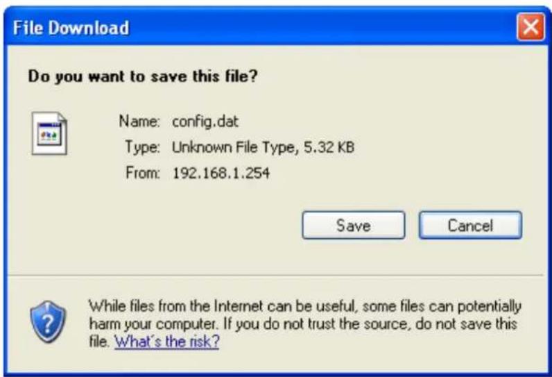
29.2 Load Settings from File
It allows you to reload the settings from the file which was saved previously.
- From the left-hand Management menu, click on Reset factory default. The following page is displayed:
Save/Reload Settings
This page allows you save current settings to a file or reload the settings from the file which was saved previously.
Besides, you could reset the current configuration to factory default.

Figure 4: Reset to Defaults page
- Click on Browse....to browse to where the config.dat is.
Save/Reload Settings
This page allows you save current settings to a file or reload the settings from the file which was saved previously.
Besides, you could reset the current configuration to factory default.

- If you are happy with this, click Upload to start to load settings from file.
Save/Reload Settings
This page allows you save current settings to a file or reload the settings from the file which was saved previously.
Besides, you could reset the current configuration to factory default.

- Once it finished loading settings form file, it'll show the message below.
Update successfully!
Update in progressing.
Do not turn off or reboot the Device during this time.
Please wait 44 seconds ...
29.3 Resetting to Defaults
If you do make changes to the default configuration but then wish to revert back to the original factory configuration, you can do so by resetting the device to factory defaults.
Note: If you reset your device to factory defaults, all previous configuration changes that you have made are overwritten by the factory default configuration
Software Reset:
- From the left-hand Management menu, click on Reset factory default. The following page is displayed:
Save/Reload Settings
This page allows you save current settings to a file or reload the settings from the file which was saved previously. Besides, you could reset the current configuration to factory default.
Save Settings to File:
Save...
Load Settings from File:
Browse...
Upload
Reset Settings to Default:
Reset
- Click on Reset Settings to Default.
Save/Reload Settings
This page allows you save current settings to a file or reload the settings from the file which was saved previously. Besides, you could reset the current configuration to factory default.
Save Settings to File:
Save...
Load Settings from File:
Browse...
Upload
Reset Settings to Default:
Reset
- This page reminds you that resetting to factory defaults cannot be undone – any changes that you have made to the basic settings will be replaced. If you are happy with this, click OK. Or click Cancel to cancel it.
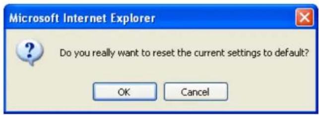
- Reload setting successfully! Please wait for a moment while rebooting ...
Reload setting successfully!
The WLAN 11n AP Router is booting. Do not turn off or reboot the Device during this time.
Please wait 56 seconds ...
- Once it finished resetting to factory, it'll show the Status page.
Status
This page shows the current status and some basic settings of the device.
| System | |
| Uptime | 0day:0h:8m:41s |
| Firmware Version | v3.2.5 |
| Customer Version | REAN_E_v325_2T2R_CAR_01_131014 |
| Build Time | Mon Oct 14 04:23:11 EDT 2013 |
| Wireless Configuration | |
| Mode | AP |
| Band | 2.4 GHz (B+G+N) |
| SSID | Hamlet |
| Channel Number | 11 |
| Encryption | Disabled |
| BSSID | 00:13:33:00:00:21 |
| Associated Clients | 0 |
| TCP/IP Configuration | |
| Attain IP Protocol | Fixed IP |
| IP Address | 192.168.1.254 |
| Subnet Mask | 255.255.255.0 |
| Default Gateway | 192.168.1.254 |
| DHCP Server | Enabled |
| MAC Address | 00:13:33:00:00:1f |
| WAN Configuration | |
| Attain IP Protocol | Getting IP from DHCP server... |
| IP Address | 0.0.0.0 |
| Subnet Mask | 0.0.0.0 |
| Default Gateway | 0.0.0.0 |
| MAC Address | 00:13:33:00:00:20 |
30. Password
You can restrict access to your device's web pages using password protection. With password protection enabled, users must enter a username and password before gaining access to the web pages.
By default, password protection is enabled on your device, and the username and password set are as follows:
Username: admin
Password: hamlet
30.1 Setting your username and password
Note: Non-authorized users may try to access your system by guessing your username and password. We recommend that you change the default username and password to your own unique settings
To change the default password:
- From the left-hand Management menu, click on Password. The following page is displayed:
Password Setup
This page is used to set the account to access the web server of Access Point. Empty user name and password will disable the protection.
User Name:
New Password:
Confirmed Password:
Apply Changes
Reset
Figure 5: Currently Defined Administration Password: Setup page
- This page displays the current username and password settings. Change your own unique password in the relevant boxes. They can be any combination of letters or numbers with a maximum of 30 characters. The default setting uses admin for the username and hamlet for password.
- If you are happy with these settings, click Apply. You will see following page that the new user has been displayed on the Currently Defined Users. You need to login to the web pages using your new username and new password.
Password Setup
This page is used to set the account to access the web server of Access Point. Empty user name and password will disable the protection.
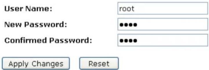
Figure 6: Administration Password
- Change setting successfully.
Change setting successfully!
Do not turn off or reboot the Router during this time.
Please wait 18 seconds ...
- Enter new User name and Password.
- Click Apply.
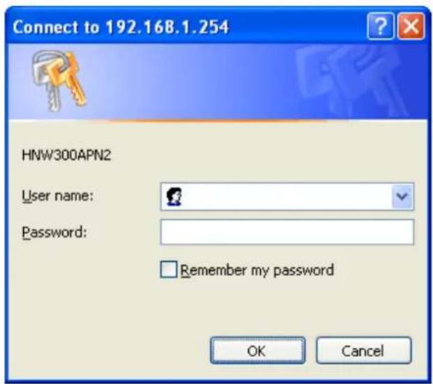
Figure 7: Login page
31. Logout
To logout:
- From the left-hand menu, click on Logout. The following page is displayed:
- Click Apply Change.
Logout
This page is used to logout.
Do you want to logout?
Apply Change
A Configuring your Computers
This appendix provides instructions for configuring the Internet settings on your computers to work with the Wireless Gateway.
Configuring Ethernet PCs
Before you begin
By default, the Wireless Gateway automatically assigns the required Internet settings to your PCs. You need to configure the PCs to accept this information when it is assigned.
Note: In some cases, you may want to assign Internet information manually to some or all of your computers rather than allow the Wireless Gateway to do so. See Assigning static Internet information to your PCs for instructions
If you have connected your LAN PCs via Ethernet to the Wireless Gateway, follow the instructions that correspond to the operating system installed on your PC:
- Windows® XP PCs
- Windows 2000 PCs
- Windows Me PCs
- Windows 95, 98 PCs
• Windows NT 4.0 workstations
Windows® XP PCs
- In the Windows task bar, click the Start button, and then click Control Panel.
- Double-click the Network Connections icon.
- In the LAN or High-Speed Internet window, right-click on the icon corresponding to your network interface card (NIC) and select Properties. (Often, this icon is labeled Local Area Connection).
- The Local Area Connection dialog box is displayed with a list of currently installed network items.
- Ensure that the check box to the left of the item labeled Internet Protocol TCP/IP is checked and click Properties.
- In the Internet Protocol (TCP/IP) Properties dialog box, click the radio button labeled Obtain an IP address automatically. Also click the radio button labeled Obtain DNS server address automatically.
- Click OK twice to confirm your changes, and then close the Control Panel.
B IP Addresses, Network Masks, and Subnets IP Addresses
Note: This section refers only to IP addresses for IPv4 (version 4 of the Internet Protocol). IPv6 addresses are not covered.
This section assumes basic knowledge of binary numbers, bits, and bytes
IP addresses, the Internet's version of telephone numbers, are used to identify individual nodes (computers or devices) on the Internet. Every IP address contains four numbers, each from 0 to 255 and separated by dots (periods), e.g. 20.56.0.211. These numbers are called, from left to right, field1, field2, field3, and field4.
This style of writing IP addresses as decimal numbers separated by dots is called dotted decimal notation. The IP address 20.56.0.211 is read "twenty dot fifty-six dot zero dot two-eleven."
Structure of an IP address
IP addresses have a hierarchical design similar to that of telephone numbers. For example, a 7-digit telephone number starts with a 3-digit prefix that identifies a group of thousands of telephone lines, and ends with four digits that identify one specific line in that group.
Similarly, IP addresses contain two kinds of information:
- Network ID
Identifies a particular network within the Internet or intranet - Host ID
Identifies a particular computer or device on the network
The first part of every IP address contains the network ID, and the rest of the address contains the host ID. The length of the network ID depends on the network's class (see following section). The table below shows the structure of an IP address.
| Field1 | Field2 | Field3 | Field4 | |
| Class A | Network ID | Host ID | ||
| Class B | Network ID | Host ID | ||
| Class C | Network ID | Host ID | ||
Here are some examples of valid IP addresses:
Class A: 10.30.6.125 (network = 10, host = 30.6.125)
Class B: 129.88.16.49 (network = 129.88, host = 16.49)
Class C: 192.60.201.11 (network = 192.60.201, host = 11)
Network classes
The three commonly used network classes are A, B, and C. (There is also a class D but it has a special use beyond the scope of this discussion.) These classes have different uses and characteristics.
Class A networks are the Internet's largest networks, each with room for over 16 million hosts. Up to 126 of these huge networks can exist, for a total of over 2 billion hosts. Because of their huge size, these networks are used for WANs and by organizations at the infrastructure level of the Internet, such as your ISP.
Class B networks are smaller but still quite large, each able to hold over 65,000 hosts. There can be up to 16,384 class B networks in existence. A class B network might be appropriate for a large organization such as a business or government agency.
Class C networks are the smallest, only able to hold 254 hosts at most, but the total possible number of class C networks exceeds 2 million (2,097,152 to be exact). LANs connected to the Internet are usually class C networks.
Some important notes regarding IP addresses:
- The class can be determined easily from field1:
field1 = 1-126: Class A
field1 = 128-191: Class B
field1 = 192-223: Class C
(field1 values not shown are reserved for special uses)
- A host ID can have any value except all fields set to 0 or all fields set to 255, as those values are reserved for special uses.
Subnet masks
Definition: A mask looks like a regular IP address, but contains a pattern of bits that tells what parts of an IP address are the network ID and what parts are the host ID: bits set to 1 mean "this bit is part of the network ID" and bits set to 0 mean "this bit is part of the host ID
Subnet masks are used to define subnets (what you get after dividing a network into smaller pieces). A subnet's network ID is created by "borrowing" one or more bits from the host ID portion of the address. The subnet mask identifies these host ID bits.
For example, consider a class C network 192.168.1. To split this into two subnets, you would use the subnet mask:
255.255.255.128
It's easier to see what's happening if we write this in binary:
-
-
- 10000000
-
As with any class C address, all of the bits in field1 through field3 are part of the network ID, but note how the mask specifies that the first bit in field4 is also included. Since this extra bit has only two values (0 and 1), this means there are two subnets. Each subnet uses the remaining 7 bits in field4 for its host IDs, which range from 1 to 126 hosts (instead of the usual 0 to 255 for a class C address).
Similarly, to split a class C network into four subnets, the mask is:
255.255.255.192 or 11111111.11111111.11111111.11000000
The two extra bits in field4 can have four values (00, 01, 10, 11), so there are four subnets. Each subnet uses the remaining six bits in field4 for its host IDs, ranging from 1 to 62.
Note: Sometimes a subnet mask does not specify any additional network ID bits, and thus no subnets. Such a mask is called a default subnet mask. These masks are:
Class A: 255.0.0.0
Class B: 255.255.0.0
Class C: 255.255.255.0
These are called default because they are used when a network is initially configured, at which time it has no subnets
C UPnP Control Point Software on Windows XP
This appendix provides instructions for configuring the UPnP on your computers to work with the Wireless Gateway.
UPnP is an architecture for pervasive peer-to-peer network connectivity of intelligent appliances, Wireless devices, and PCs of all form factors. It is designed to bring easy-to-use, flexible, standards-based connectivity to ad-hoc or unmanaged networks whether in the home, in a small business, public spaces, or attached to the Internet. UPnP is a distributed, open networking architecture that leverages TCP/IP and the Web technologies to enable seamless proximity networking in addition to control and data transfer among networked devices in the home, office, and public spaces.
UPnP is more than just a simple extension of the plug and play peripheral model. It is designed to support zero-configuration, "invisible" networking, and automatic discovery for a breadth of device categories from a wide range of vendors. This means a device can dynamically join a network, obtain an IP address, convey its capabilities, and learn about the presence and capabilities of other devices. DHCP and DNS servers are optional and are used only if available on the network. Finally, a device can leave a network smoothly and automatically without leaving any unwanted state behind.
UPnP Control Point Software on Windows XP with Firewall
On Windows XP versions earlier than SP2, Firewall support is provided by the Windows XP Internet Connection Firewall. You cannot use the Windows XP Internet Connection Firewall support on a system that you intend to use as a UPnP control point. If this feature is enabled, although the control point system may display controlled devices in the list of network devices, the control point system cannot participate in UPnP communication. (This restriction also applies to controlled devices running on Windows XP systems earlier than SP2.)
On Windows XP SP2 and later, Firewall support is provided by Windows Firewall. Unlike earlier versions, Windows XP SP2 can be used on a system that you intend to use as a UPnP control point.
To turn off the Firewall capability on any version of Windows XP, follow the steps below:
- In the "Control Panel", select "Network and Internet Connections".
- In the "Network and Internet Connections" dialog box, select "Network Connections".
- In the "Network Connections" dialog box, right-click on the local area connection entry for your network; this will display a menu. Select the "Properties" menu entry.
- In the "Local Area Connection Properties" dialog box, select the "Advanced" tab. Disable the Internet Connection Firewall by de-selecting the entry with the following label:
"Protect my computer and network by limiting or preventing access to the computer from the Internet".
- Click "OK".
SSDP requirements
You must have SSDP Discovery Service enabled on your Windows XP system to use the UPnP Control point software.
SSDP Discovery Service is enabled on a default installation of Windows XP. To check if it is enabled on your system, look in Control Panel > Administrative Tools > Services).
Installation procedure
To install the Control point software on Windows XP, follow the steps below:
-
In the "Control Panel", select "Add/Remove Programs".
-
In the "Add or Remove Programs" dialog box, click the "Add / Remove Windows Components" button.
- In the "Windows Component Wizard" dialog box, scroll down the list to display the "Networking Services" entry. Highlight (select) the entry, and click on the "Details" button.
- The "Networking Services" window is displayed.
The subcomponents shown in the Networking Services window will be different depending on if you are using Windows XP, Windows XP (SP1), or Windows XP (SP2).
If you are using Windows XP SP2, the Networking Services window will display the following list of sub-components:
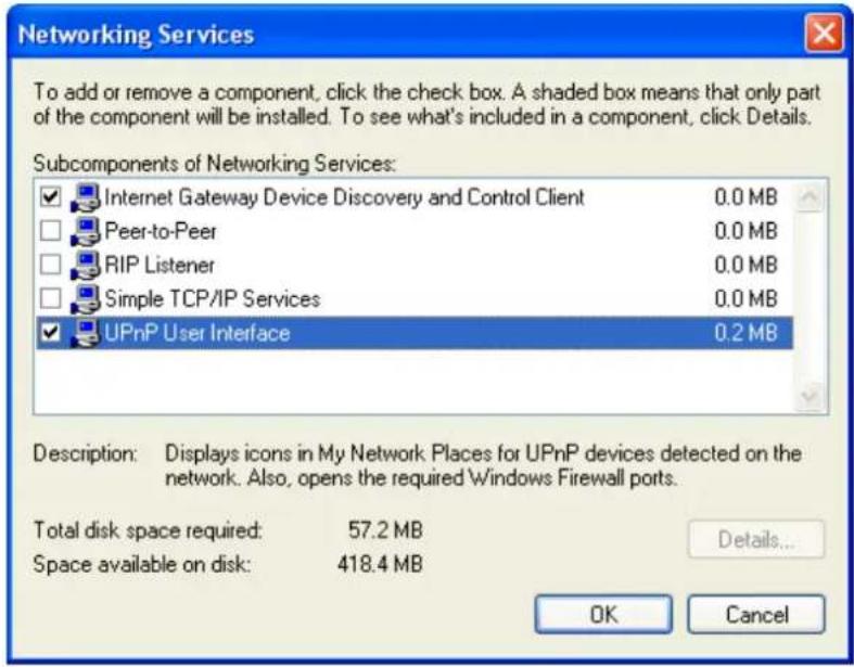
- Select the following entries from the "Networking Services" window and then click "OK":
If you are using Windows XP, select:
• "Universal Plug and Play".
If you are using Windows XP SP1, select:
- "Internet Gateway Device discovery and Control Client".
• "Universal Plug and Play".
If you are using Windows XP SP2, select:
- "Internet Gateway Device discovery and Control Client".
-
"UPnP User Interface".
-
Reboot your system.
Once you have installed the UPnP software and you have rebooted (and your network includes the IGD system), you should be able to see the IGD controlled device on your network.
For example, from the Network Connections window you should see the Internet Gateway Device:
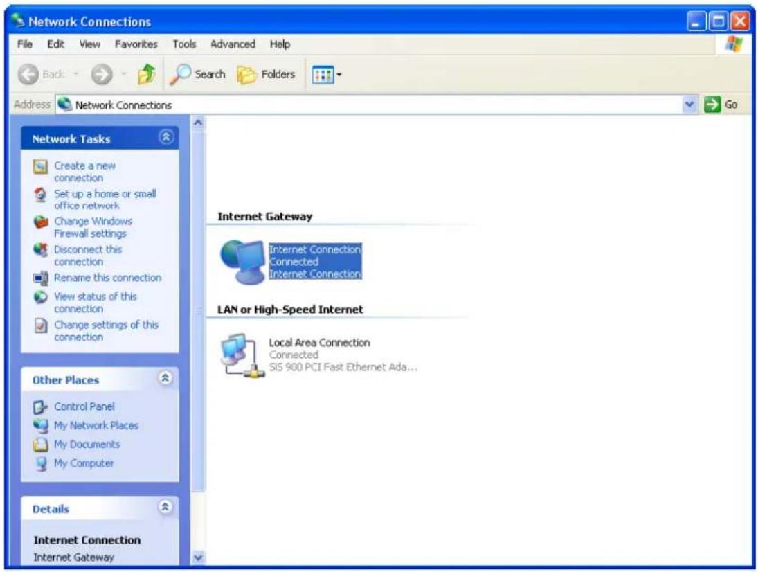
D Troubleshooting
This appendix suggests solutions for problems you may encounter in installing or using the Wireless Gateway, and provides instructions for using several IP utilities to diagnose problems.
Contact Customer Support if these suggestions do not resolve the problem.
Troubleshooting Suggestions
| Problem | Troubleshooting Suggestion |
| LEDs | |
| Power LED does not illuminate after product is turned on. | Verify that you are using the power cable provided with the device and that it is securely connected to the Wireless Gateway and a wall socket/power strip. |
| LINK LAN LED does not illuminate after Ethernet cable is attached. | Verify that the Ethernet cable is securely connected to your LAN hub or PC and to the Wireless Gateway. Make sure the PC and/or hub is turned on.Verify that your cable is sufficient for your network requirements. A 100 Mbit/sec network (10BaseTx) should use cables labeled CAT 5. A 10Mbit/sec network may tolerate lower quality cables. |
| Internet Access | |
| My PC cannot access the Internet | Use the ping utility (discussed in the following section) to check whether your PC can communicate with the device's LAN IP address (by default 192.168.1.254). If it cannot, check the Ethernet cabling. If you statically assigned a private IP address to the computer, (not a registered public address), verify the following:Check that the gateway IP address on the computer is your public IP address (see Current Status for instructions on viewing the IP information.) If it is not, correct the address or configure the PC to receive IP information automatically.Verify with your ISP that the DNS server specified for the PC is valid. Correct the address or configure the PC to receive this information automatically. |
| My LAN PCs cannot display web pages on the Internet. | Verify that the DNS server IP address specified on the PCs is correct for your ISP, as discussed in the item above. If you specified that the DNS server be assigned dynamically from a server, then verify with your ISP that the address configured on the Wireless Gateway is correct, then You can use the ping utility, to test connectivity with your ISP's DNS server. |
| Web pages | |
| I forgot/lost my user ID or password. | If you have not changed the password from the default, try using “admin” the user ID and “hamlet” as password. Otherwise, you can reset the device to the default configuration by pressing the Reset Default button on the Rare panel of the device (see Rare Panel). Then, type the default User ID and password shown above.WARNING: Resetting the device removes any custom settings and returns all settings to their default values. |
| I cannot access the web pages from my browser. | Use the ping utility, discussed in the following section, to check whether your PC can communicate with the device's LAN IP address (by default 192.168.1.254). If it cannot, check the Ethernet cabling. Verify that you are using Internet Explorer or Netscape Navigator v4.0 later.Verify that the PC's IP address is defined as being on the same subne as the IP address assigned to the LAN port on the Wireless Gateway. |
| My changes to the web pages are not being retained. | Be sure to use the Confirm Changes/Apply function after any changes |
Diagnosing Problem using IP Utilities
ping
Ping is a command you can use to check whether your PC can recognize other computers on your network and the Internet. A ping command sends a message to the computer you specify. If the computer receives the message, it sends messages in reply. To use it, you must know the IP address of the computer with which you are trying to communicate.
On Windows-based computers, you can execute a ping command from the Start menu. Click the Start button, and then click Run. In the Open text box, type a statement such as the following:
ping 192.168.1.254
Click OK. You can substitute any private IP address on your LAN or a public IP address for an Internet site, if known.
If the target computer receives the message, a Command Prompt window is displayed:
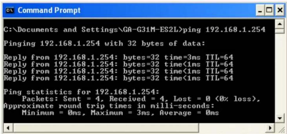
Figure 8: Using the ping Utility
If the target computer cannot be located, you will receive the message Request timed out.
Using the ping command, you can test whether the path to the Wireless Gateway is working (using the preconfigured default LAN IP address 192.168.1.254) or another address you assigned.
You can also test whether access to the Internet is working by typing an external address, such as that for www.yahoo.com (216.115.108.243). If you do not know the IP address of a particular Internet location, you can use the nslookup command, as explained in the following section.
From most other IP-enabled operating systems, you can execute the same command at a command prompt or through a system administration utility.
nslookup
You can use the nslookup command to determine the IP address associated with an Internet site name. You specify the common name, and the nslookup command looks up the name in on your DNS server (usually located with your ISP). If that name is not an entry in your ISP's DNS table, the request is then referred to another higher-level server, and so on, until the entry is found. The server then returns the associated IP address.
On Windows-based computers, you can execute the nslookup command from the Start menu. Click the Start button, and then click Run. In the Open text box, type the following:
nslookup
Click OK. A Command Prompt window displays with a bracket prompt (>). At the prompt, type the name of the Internet address that you are interested in, such as www.microsoft.com.
The window will display the associate IP address, if known, as shown below:
Figure 9: Using the nslookup Utility
There may be several addresses associated with an Internet name. This is common for web sites that receive heavy traffic; they use multiple, redundant servers to carry the same information.
To exit from the nslookup utility, type exit and press [Enter] at the command prompt.
E Glossary
| 10BASE-T | A designation for the type of wiring used by Ethernet networks with a data rate of 10 Mbps. Also known as Category 3 (CAT 3) wiring. See data rate, Ethernet. |
| 100BASE-T | A designation for the type of wiring used by Ethernet networks with a data rate of 100 Mbps. Also known as Category 5 (CAT 5) wiring. See data rate, Ethernet. |
| ADSL Asymmetric Digital Subscriber Line | |
| The most commonly deployed "flavor" of DSL for home users is asymmetrical DSL. The term asymmetrical refers to its unequal data rates for downloading and uploading (the download rate is higher than the upload rate). The asymmetrical rates benefit home users because they typically download much more data from the Internet than they upload. | |
| analog | An analog signal is a signal that has had its frequency modified in some way, such as by amplifying its strength or varying its frequency, in order to add information to the signal. The voice component in DSL is an analog signal. See digital. |
| ATM Asynchronous Transfer Mode | |
| A standard for high-speed transmission of data, text, voice, and video, widely used within the Internet. ATM data rates range from 45 Mbps to 2.5 Gbps. See data rate. | |
| authenticate | To verify a user's identity, such as by prompting for a password. |
| binary | The "base two" system of numbers, that uses only two digits, 0 and 1, to represent all numbers. In binary, the number 1 is written as 1, 2 as 10, 3 as 11, 4 as 100, etc. Although expressed as decimal numbers for convenience, IP addresses in actual use are binary numbers; e.g., the IP address 209.191.4.240 is 11010001.10111111.00000100.11110000 in binary. See bit, IP address, network mask. |
| bit | Short for "binary digit," a bit is a number that can have two values, 0 or 1. See binary. |
| bps | bits per second |
| bridging | Passing data from your network to your ISP and vice versa using the hardware addresses of the devices at each location. Bridging contrasts with routing, which can add more intelligence to data transfers by using network addresses instead. The Wireless Gateway can perform both routing and bridging. Typically, when both functions are enabled, the device routes IP data and bridges all other types of data. See routing. |
| broadband | A telecommunications technology that can send different types of data over the same medium. DSL is a broadband technology. |
| broadcast | To send data to all computers on a network. |
| DHCP | Dynamic Host Configuration ProtocolDHCP automates address assignment and management. When a computer connects to the LAN, DHCP assigns it an IP address from a shared pool of IP addresses; after a specified time limit, DHCP returns the address to the pool. |
| DHCP relay | Dynamic Host Configuration Protocol relayA DHCP relay is a computer that forwards DHCP data between computers that request IP addresses and the DHCP server thatassigns the addresses. Each of the Wireless Gateway's interfaces can be configured as a DHCP relay. See DHCP. |
| DHCP server Dynamic Host Configuration Protocol server | |
| A DHCP server is a computer that is responsible for assigning IP addresses to the computers on a LAN. See DHCP. | |
| digital | Of data, having a form based on discrete values expressed as binary numbers (0's and 1's). The data component in DSL is a digital signal. See analog. |
| DNS Domain Name System | |
| The DNS maps domain names into IP addresses. DNS information is distributed hierarchically throughout the Internet among computers called DNS servers. For example, www.yahoo.com is the domain name associated with IP address 216.115.108.243. When you start to access a web site, a DNS server looks up the requested domain name to find its corresponding IP address. If the DNS server cannot find the IP address, it communicates with higher-level DNS servers to determine the IP address. See domain name. | |
| domain name | A domain name is a user-friendly name used in place of its associated IP address. Domain names must be unique; their assignment is controlled by the Internet Corporation for Assigned Names and Numbers (ICANN). Domain names are a key element of URLs, which identify a specific file at a web site. See DNS. |
| download | To transfer data in the downstream direction, i.e., from the Internet to the user. |
| DSL Digital Subscriber Line | |
| A technology that allows both digital data and analog voice signals to travel over existing copper telephone lines. | |
| encryption keys | See network keys |
| Ethernet | The most commonly installed computer network technology, usually using twisted pair wiring. Ethernet data rates are 10 Mbps and 100 Mbps. See also 10BASE-T, 100BASE-T, twisted pair. |
| FTP File Transfer Protocol | |
| A program used to transfer files between computers connected to the Internet. Common uses include uploading new or updated files to a web server, and downloading files from a web server. | |
| Gbps | Abbreviation of Gigabits per second, or one billion bits per second. Internet data rates are often expressed in Gbps. |
| host | A device (usually a computer) connected to a network. |
| HTTP | Hyper-Text Transfer ProtocolHTTP is the main protocol used to transfer data from web sites so that it can be displayed by web browsers. See web browser, web site. |
| Hub | A hub is a place of convergence where data arrives from one or more directions and is forwarded out in one or more directions. It connects an Ethernet bridge/router to a group of PCs on a LAN and allows communication to pass between the networked devices. |
| ICMP | Internet Control Message ProtocolAn Internet protocol used to report errors and other network-related information. The ping command makes use of ICMP. |
| IEEE | The Institute of Electrical and Electronics Engineers is a technical professional society that fosters the development of standards that often become national and international standards. |
| Internet | The global collection of interconnected networks used for both private and business communications. |
| intranet | A private, company-internal network that looks like part of the Internet (users access information using web browsers), but is accessible only by employees. |
| IP See TCP/IP. | |
| IP address Internet Protocol address | |
| The address of a host (computer) on the Internet, consisting of four numbers, each from 0 to 255, separated by periods, e.g., 209.191.4.240. An IP address consists of a network ID that identifies the particular network the host belongs to, and a host ID uniquely identifying the host itself on that network. A network mask is used to define the network ID and the host ID. Because IP addresses are difficult to remember, they usually have an associated domain name that can be specified instead. See domain name, network mask. | |
| ISP Internet Service Provider | |
| A company that provides Internet access to its customers, usually for a fee. | |
| LAN Local Area Network | |
| A network limited to a small geographic area, such as a home or small office. | |
| LED Light Emitting Diode | |
| An electronic light-emitting device. The indicator lights on the front of the Wireless Gateway are LEDs. | |
| MAC address Media Access Control address | |
| The permanent hardware address of a device, assigned by its manufacturer. MAC addresses are expressed as six pairs of hex characters, with each pair separated by colons. For example; NN:NN:NN:NN:NN:NN. | |
| mask See network mask. | |
| Mbps | Abbreviation for Megabits per second, or one million bits per second. Network data rates are often expressed in Mbps. |
| NAT Network Address Translation | |
| A service performed by many routers that translates your network's publicly known IP address into a private IP address for each computer on your LAN. Only your router and your LAN know these addresses; the outside world sees only the public IP address when talking to a computer on your LAN. | |
| network | A group of computers that are connected together, allowing them to communicate with each other and share resources, such as software, files, etc. A network can be small, such as a LAN, or very large, such as the Internet. |
| network mask | A network mask is a sequence of bits applied to an IP address to select the network ID while ignoring the host ID. Bits set to 1 mean "select this bit" while bits set to 0 mean "ignore this bit." For example, if the network mask 255.255.255.0 is applied to the IP address 100.10.50.1, the network ID is 100.10.50, and the host ID is 1. See binary, IP address, subnet. |
| NIC | Network Interface Card |
| An adapter card that plugs into your computer and provides the physical interface to your network cabling. For Ethernet NICs this is typically an RJ-45 connector. See Ethernet, RJ-45. | |
| packet | Data transmitted on a network consists of units called packets. Each packet contains a payload (the data), plus overhead information such as where it came from (source address) and where it should go (destination address). |
| ping | Packet Internet (or Inter-Network) GroperA program used to verify whether the host associated with an IP address is online. It can also be used to reveal the IP address for a given domain name. |
| port | A physical access point to a device such as a computer or router, through which data flows into and out of the device. |
| PPP | Point-to-Point ProtocolA protocol for serial data transmission that is used to carry IP (and other protocol) data between your ISP and your computer. The WAN interface on the Wireless Gateway uses two forms of PPP called PPPoA and PPPoE. See PPPoA, PPPoE. |
| PPPoA | Point-to-Point Protocol over ATMOne of the two types of PPP interfaces you can define for a Virtual Circuit (VC), the other type being PPPoE. You can define only one PPPoA interface per VC. |
| PPPoE | Point-to-Point Protocol over EthernetOne of the two types of PPP interfaces you can define for a Virtual Circuit (VC), the other type being PPPoA. You can define one or more PPPoE interfaces per VC. |
| protocol | A set of rules governing the transmission of data. In order for a data transmission to work, both ends of the connection have to follow the rules of the protocol. |
| remote | In a physically separate location. For example, an employee away on travel who logs in to the company's intranet is a remote user. |
| RIP Routing Information Protocol | |
| The original TCP/IP routing protocol. There are two versions of RIP: version I and version II. | |
| RJ-11 | Registered Jack Standard-11The standard plug used to connect telephones, fax machines, modems, etc. to a telephone port. It is a 6-pin connector usually containing four wires. |
| RJ-45 | Registered Jack Standard-45The 8-pin plug used in transmitting data over phone lines. Ethernet cabling usually uses this type of connector. |
| routing | Forwarding data between your network and the Internet on the most efficient route, based on the data's destination IP address and current network conditions. A device that performs routing is called a router. |
| SDNS | Secondary Domain Name System (server)A DNS server that can be used if the primary DSN server is not available. See DNS. |
| subnet | A subnet is a portion of a network. The subnet is distinguished from the larger network by a subnet mask that selects some of the computers of the network and excludes all others. The subnet's computers remain physically connected to the rest of the parent network, but they are treated as though they were on a separate network. See network mask. |
| subnet mask | A mask that defines a subnet. See network mask. |
| TCP See TCP/IP. | |
| TCP/IP | Transmission Control Protocol/Internet ProtocolThe basic protocols used on the Internet. TCP is responsible for dividing data up into packets for delivery and reassembling them at the destination, while IP is responsible for delivering the packets from source to destination. When TCP and IP are bundled with higher-level applications such as HTTP, FTP, Telnet, etc., TCP/IP refers to this whole suite of protocols. |
| Telnet | An interactive, character-based program used to access a remote computer. While HTTP (the web protocol) and FTP only allow you to download files from a remote computer, Telnet allows you to log into and use a computer from a remote location. |
| TFTP Trivial File Transfer Protocol | A protocol for file transfers, TFTP is easier to use than File Transfer Protocol (FTP) but not as capable or secure. |
| TKIP Temporal Key Integrity Protocol (TKIP) provides WPA with a data encryption function. It ensures that a unique master key is generated for each packet, supports message integrity and sequencing rules and supports re-keying mechanisms. | |
| triggers | Triggers are used to deal with application protocols that create separate sessions. Some applications, such as NetMeeting, open secondary connections during normal operations, for example, a connection to a server is established using one port, but data transfers are performed on a separate connection. A trigger tells the device to expect these secondary sessions and how to handle them.Once you set a trigger, the embedded IP address of each incoming packet is replaced by the correct host address so that NAT can translate packets to the correct destination. You can specify whether you want to carry out address replacement, and if so, whether to replace addresses on TCP packets only, UDP packets only, or both. |
| twisted pair | The ordinary copper telephone wiring used by telephone companies. It contains one or more wire pairs twisted together to reduce inductance and noise. Each telephone line uses one pair. In homes, it is most often installed with two pairs. For Ethernet LANs, a higher grade called Category 3 (CAT 3) is used for 10BASE-T networks, and an even higher grade called Category 5 (CAT 5) is used for 100BASE-T networks. See 10BASE-T, 100BASE-T, Ethernet. |
| unnumbered interfaces | An unnumbered interface is an IP interface that does not have a local subnet associated with it. Instead, it uses a router-id that serves as the source and destination address of packets sent to and from the router. Unlike the IP address of a normal interface, the router-id of an unnumbered interface is allowed to be the same as the IP address of another interface. For example, the WAN unnumbered interface of your device uses the same IP address of the LAN interface (192.168.1.254). |
| The unnumbered interface is temporary – PPP or DHCP will assign a ‘real’ IP address automatically. | |
| upstream | The direction of data transmission from the user to the Internet. |
| VC | Virtual CircuitA connection from your DSL router to your ISP. |
| VCI | Virtual Circuit IdentifierTogether with the Virtual Path Identifier (VPI), the VCI uniquely identifies a VC. Your ISP will tell you the VCI for each VC they provide. See VC. |
| VPI | Virtual Path IdentifierTogether with the Virtual Circuit Identifier (VCI), the VPI uniquelyidentifies a VC. Your ISP will tell you the VPI for each VC they provide. See VC. |
| WAN Wide Area Network | Any network spread over a large geographical area, such as a country or continent. With respect to the Wireless Gateway, WAN refers to the Internet. |
| Web browser | A software program that uses Hyper-Text Transfer Protocol (HTTP) to download information from (and upload to) web sites, and displays the information, which may consist of text, graphic images, audio, or video, to the user. Web browsers use Hyper-Text Transfer Protocol (HTTP). Popular web browsers include Netscape Navigator and Microsoft Internet Explorer. See HTTP, web site, WWW. |
| Web page | A web site file typically containing text, graphics and hyperlinks (cross-references) to the other pages on that web site, as well as to pages on other web sites. When a user accesses a web site, the first page that is displayed is called the home page. See hyperlink, web site. |
| Web site | A computer on the Internet that distributes information to (and gets information from) remote users through web browsers. A web site typically consists of web pages that contain text, graphics, and hyperlinks. See hyperlink, web page. |
| WWW World Wide Web | Also called (the) Web. Collective term for all web sites anywhere in the world that can be accessed via the Internet. |
- INDEX
- Introduction......6
- Specification....7
- Installation & Setup....9
- Configuration Procedures....10
- Wi-Fi Router Configuration....21
- Connect Wirelessly 26
- Web Configuration ...... 28
- Quick Setup....29
- Operation Mode....56
- Wireless Network 57
- LAN Interface.... 103
- WAN Interface.... 109
- Port Filtering.... 118
- IP Filtering.... 121
- MAC Filtering.... 125
- Port Forwarding 127
- URL Filtering.... 130
- DMZ 132
- VLAN 134
- QoS 135
- Route Setup.... 136
- Status.... 137
- Statistics.... 138
- Dynamic DNS.... 139
- Time Zone Setting 143
- Denial-of-Service.... 144
- Log 146
- Logout.... 156
- A Configuring your Computers....157
- B IP Addresses, Network Masks, and Subnets 158
- C UPnP Control Point Software on Windows XP 160
- D Troubleshooting 163
- E Glossary 166
- Dear Customer,
- Responsibility Statement
- Trademarks
- Changes
- Introduction
- System Requirements
- Package Contents
- Specification
- LED Meaning
- Connectors
- Installation & Setup
- Connection of Wi-Fi Router
- Configuration Procedures
- Windows 98SE/ME/2000/XP
- Windows Vista
- Windows 7
- Windows 8
- Click on "View network status and tasks".
- In the Control Panel Home, click on "Change adapter settings" to continue.
- Wi-Fi Router Configuration
- Configuration examples
- 7-1. PPPoE
- 7-2. DHCP
- 7-3. Fixed IP
- Connect Wirelessly
- Web Configuration
- Accessing the Web Interface
- Status
- Quick Setup
- Quick Setup
- Operation Mode Setup
- Gateway:
- Wireless ISP:
- Operation Mode Setup
- Gateway
- Wireless ISP
- WAN Interface Setup
- WAN Interface Setup
- WAN Access Type:
- Static IP
- DHCP Client
- PPPoE
- PPTP
- L2TP
- Wireless Basic Setup
- Wireless Basic Settings
- AP (Access Point)
- Client
- WDS (Wireless Distribution System)
- Main WDS station:
- Repeater WDS stations:
- WDS (Wireless Distribution System) only
- AP (Access Point) + WDS (Wireless Distribution System)
- Wireless Security Setup
- Wireless Security Setup
- Encryption:
- Configuring WEP 64bit ASCII (5 characters) security
- Configuring WEP 64bit Hex (10 characters) security
- Configuring WEP 128bit ASCII (13 characters) security
- Configuring WEP 128bit Hex (26 characters) security
- Configuring WPA (AES) Passphrase security
- Configuring WPA (AES) HEX (64 characters) security
- Configuring WPA2 (AES) Passphrase security
- Configuring WPA2 (AES) HEX (64 characters) security
- Configuring WPA2 (Mixed) HEX (64 characters) security
- Operation Mode
- Setting Operation Mode
- Operation Mode
- Bridge:
- ○ Wireless ISP:
- Wireless Network
- Basic Settings
- Disable Wireless LAN Interface
- Advanced Settings
- Wireless Advanced Settings
- Security
- WEP + Encryption Key
- Change setting successfully!
- WEP + Use 802.1x Authentication
- WPA/WPA2/WPA2 Mixed + Personal (Pre-Shared Key)
- WPA/WPA2/WPA2 Mixed + Enterprise (RADIUS)
- Access Control
- Wireless Access Control
- Allow Listed
- Deny Listed
- WDS settings
- WDS Settings
- Configure WDS (Wireless Distribution System) only
- Enable WDS
- Current WDS AP List:
- WDS Security Setup
- Click Apply Changes button.
- Configure AP (Access Point) + WDS (Wireless Distribution System)
- □ Disable Wireless LAN Interface
- Click Apply Changes button.
- Change setting successfully! Click on Reboot Now button to confirm.
- Click Close button to close and exit the WDS Security Setup.
- Site Survey
- Wireless Site Survey
- Configure Wireless ISP + Wireless client + Site Survey
- ○ Bridge:
- Apply Change
- Reset
- Do not turn off or reboot the Device during this time.
- Please wait 17 seconds ...
- Click Apply Changes button.
- Click Next button
- Click Next button.
- Connect successfully!
- WPS
- Wi-Fi Protected Setup
- Introduction of WPS
- Supported WPS features
- AP mode
- AP as Enrollee
- AP as Registrar
- AP as Proxy
- Infrastructure-Client mode
- Instructions of AP's and Client's operations
- Wireless Advanced Settings page
- Fragment Threshold:
- Operations of AP - AP being an enrollee
- Operations of AP - AP being a registrar
- Push Button method
- Wireless Schedule
- Wireless Schedule
- LAN Interface
- LAN Interface Setup
- LAN Interface Setup
- Changing the LAN IP address and subnet mask
- Windows 95/98
- Windows NT/Windows 2000/Windows XP
- Linux
- Show Client
- Active DHCP Client Table
- WAN Interface
- Configuring Static IP connection
- Configuring DHCP Client connection
- Configuring PPPoE connection
- Configuring PPTP connection
- Configuring L2TP connection
- Clone MAC Address
- Port Filtering
- Port Filtering
- Port filtering for TCP port 80
- Current Filter Table:
- Port filtering for UDP port 53
- IP Filtering
- IP Filtering
- IP filtering for TCP with specified IP
- IP filtering for UDP with specified IP
- IP filtering for both TCP and UDP with specified IP
- MAC Filtering
- MAC Filtering
- MAC filtering for specified MAC Address
- Port Forwarding
- Port Forwarding
- Current Port Forwarding Table:
- Port Forwarding for TCP with specified IP
- Port Forwarding for UDP with specified IP
- URL Filtering
- URL Filtering
- Enable URL Filtering
- URL filtering for specified URL Address
- DMZ
- DMZ
- DMZ Host IP Address
- VLAN
- VLAN Settings
- QoS
- QoS
- Route Setup
- Routing Setup
- Status
- Statistics
- Statistics
- Dynamic DNS
- Overview
- Registering With Dynamic DNS Service Provider
- Configuring IP Interfaces
- Dynamic DNS Setting
- Configure DynDNS
- Configure TZO
- Enable DDNS
- Time Zone Setting
- SNTP Server and SNTP Client Configuration settings
- Time Zone Setting
- Denial-of-Service
- Denial of Service
- Enable DoS Prevention
- Select ALL Clear ALL
- Apply Changes
- Log
- System Log
- Firmware Update
- About firmware versions
- Manually updating firmware
- Upgrade Firmware
- Save/Reload Settings
- Save Settings to File
- Save/Reload Settings
- Click on Save....
- Load Settings from File
- Update successfully!
- Resetting to Defaults
- Reload setting successfully!
- Password
- Setting your username and password
- Password Setup
- Do not turn off or reboot the Router during this time.
- Please wait 18 seconds ...
- Logout
- Logout
- A Configuring your Computers
- Configuring Ethernet PCs
- Before you begin
- Windows® XP PCs
- B IP Addresses, Network Masks, and Subnets IP Addresses
- Structure of an IP address
- Network classes
- Subnet masks
- C UPnP Control Point Software on Windows XP
- UPnP Control Point Software on Windows XP with Firewall
- SSDP requirements
- Installation procedure
- D Troubleshooting
- Diagnosing Problem using IP Utilities
- ping
- ping 192.168.1.254
- nslookup
- E Glossary
Brand : Hamlet
Model : HNW300APN2
Category : Router