Hi-Fi Z87X 3D - Motherboard BIOSTAR - Free user manual and instructions
Find the device manual for free Hi-Fi Z87X 3D BIOSTAR in PDF.

| Product Type | Motherboard |
| Form Factor | ATX |
| Socket | LGA1150 |
| Chipset | Intel Z87 |
| Supported Processors | 4th Gen Intel Core i7/i5/i3/Pentium/Celeron |
| Memory | 4 x DDR3 DIMM, Dual Channel, up to 32GB, 2600(OC)/2400(OC)/1600/1333/1066 MHz |
| Slots | 2 x PCIe 3.0 x16, 2 x PCIe 2.0 x1, 2 x PCI |
| Storage | 6 x SATA 6Gb/s, 1 x M.2 (Key E for Wi-Fi) |
| USB | 4 x USB 3.0 (2 rear, 2 via header), 8 x USB 2.0 (4 rear, 4 via header) |
| Audio | Realtek ALC898 8-Channel HD Audio, Hi-Fi 3D Technology |
| LAN | Realtek RTL8111G Gigabit Ethernet |
| Back I/O Ports | PS/2 keyboard/mouse, DVI-D, HDMI, 2 x USB 2.0, 2 x USB 3.0, RJ-45, Audio jacks |
| Dimensions | 305 mm x 244 mm (12.0 in x 9.6 in) |
| Weight | Approximately 1.2 kg (2.65 lbs) |
| Power Connectors | 24-pin ATX, 8-pin CPU |
| BIOS | AMI UEFI BIOS, 64 Mb Flash ROM |
| Maintenance | Use a soft dry cloth for cleaning; avoid liquids. Keep vents clear. |
| Safety | Install on a non-conductive surface; handle by edges; anti-static precautions recommended. |
| Spare Parts & Repairability | Not user-serviceable; contact Biostar support for replacements or repairs. |
| General Information | Supports Smart Response, Rapid Start, Smart Connect technologies; Biostar Hi-Fi 3D audio circuit design. |
Frequently Asked Questions - Hi-Fi Z87X 3D BIOSTAR
User questions about Hi-Fi Z87X 3D BIOSTAR
0 question about this device. Answer the ones you know or ask your own.
Ask a new question about this device
Download the instructions for your Motherboard in PDF format for free! Find your manual Hi-Fi Z87X 3D - BIOSTAR and take your electronic device back in hand. On this page are published all the documents necessary for the use of your device. Hi-Fi Z87X 3D by BIOSTAR.
USER MANUAL Hi-Fi Z87X 3D BIOSTAR
FCC Information and Copyright
This equipment has been tested and found to comply with the limits of a Class B digital device, pursuant to Part 15 of the FCC Rules. These limits are designed to provide reasonable protection against harmful interference in a residential installation. This equipment generates, uses, and can radiate radio frequency energy and, if not installed and used in accordance with the instructions, may cause harmful interference to radio communications. There is no guarantee that interference will not occur in a particular installation.
The vendor makes no representations or warranties with respect to the contents here and specially disclaims any implied warranties of merchantability or fitness for any purpose. Further the vendor reserves the right to revise this publication and to make changes to the contents here without obligation to notify any party beforehand.
Duplication of this publication, in part or in whole, is not allowed without first obtaining the vendor's approval in writing.
The content of this user's manual is subject to be changed without notice and we will not be responsible for any mistakes found in this user's manual. All the brand and product names are trademarks of their respective companies.

2004/108/CE, 2006/95/CE e 1999/05/CE
Short Declaration of conformity
We declare this product is complying with the laws in force and meeting all the essential requirements as specified by the directives
2004/108/CE, 2006/95/CE and 1999/05/CE
whenever these laws may be applied
Table of Contents
Chapter 1: Introduction ...... 1
1.1 Before You Start ....1
1.2 Package Checklist ....1
1.3 Motherboard Specifications 2
1.4 Rear Panel Connectors....3
1.5 Motherboard Layout....4
Chapter 2: Hardware Installation .... 5
2.1 Install Central Processing Unit (CPU)....5
2.2 Install a Heatsink....7
2.3 Connect Cooling Fans....8
2.4 Install System Memory....9
2.5 Expansion Slots....10
2.6 Jumper Setting 12
2.7 Headers & Connectors....13
2.8 Smart Switches & Indicators....18
Chapter 3: UEFI BIOS & Software.... 19
3.1 UEFI BIOS Setup....19
3.2 BIOS Update....19
3.3 Software....23
Chapter 4: Useful Help.... 38
4.1 Driver Installation....39
4.2 AMI BIOS Beep Code....40
4.3 AMI BIOS Post Code....40
4.4 Troubleshooting....42
4.5 RAID Functions 43
Appendix: Specifications in Other Languages 46
Arabic....46
French 48
German 50
Italian 52
Japanese....54
Polish....56
Portuguese ....58
Russian 60
Spanish....62
CHAPTER 1: INTRODUCTION
1.1 Before You Start
Thank you for choosing our product. Before you start installing the motherboard, please make sure you follow the instructions below:
■ Prepare a dry and stable working environment with sufficient lighting.
■ Always disconnect the computer from power outlet before operation.
■ Before you take the motherboard out from anti-static bag, ground yourself properly by touching any safely grounded appliance, or use grounded wrist strap to remove the static charge.
■ Avoid touching the components on motherboard or the rear side of the board unless necessary. Hold the board on the edge, do not try to bend or flex the board.
■ Do not leave any unfastened small parts inside the case after installation. Loose parts will cause short circuits which may damage the equipment.
- Keep the computer from dangerous area, such as heat source, humid air and water.
■ The operating temperatures of the computer should be 0 to 45 degrees Celsius.
■ To avoid injury, be careful of:
Sharp pins on headers and connectors
Rough edges and sharp corners on the chassis
Damage to wires that could cause a short circuit
1.2 Package Checklist
☑ Serial ATA Cable x4
☑ Rear I/O Panel for ATX Case x1
User's Manual x1
☑ Fully Setup Driver DVD x1
☑ CFX Bridge x1
☑ Calibration Microphone x1
Note: The package contents may be different due to the sales region or models in which it was sold. For more information about the standard package in your region, please contact your dealer or sales representative.
1.3 Motherboard Specifications
| Specifications | |
| CPU Support | Socket 1150 for Intel® Core i7 / i5 / i3 / Pentium / Celeron processorMaximum CPU TDP (Thermal Design Power): 95Watt* Please refer towww.biostar.com.twfor CPU support list. |
| Chipset | INTEL® Z87 |
| Memory | Supports Dual Channel DDR3 1066/ 1333/ 1600/ 1800(OC) / 1866(OC) / 2133(OC) / 2200(OC) / 2400(OC) / 2600(OC) / 2667(OC)4 x DDR3 DIMM Memory Slot, Max. Supports up to 32 GB MemoryEach DIMM supports non-ECC 512MB/ 1/ 2/ 4/ 8 GB DDR3 module* Please refer towww.biostar.com.twfor Memory support list. |
| Storage | INTEL® Z876x SATA 6Gb/s ConnectorSupports RAID 0,1,10,5, AHCI & SRT |
| LAN | Realtek RTL 8111F10/ 100/ 1000 Mb/s auto negotiation, Half / Full duplex capability |
| Audio Codec | ALC8987.1 Channels, High Definition Audio, Biostar Hi-Fi 3D |
| USB | 4x USB 3.0 port (2 on rear I/Os and 2 via internal headers)8x USB 2.0 port (4 on rear I/Os and 4 via internal headers) |
| Expansion Slots | 3x PCIe 2.0 x1 Slot1x PCIe 2.0 x16 Slot (x4)2x PCIe 3.0 x16 Slot (x8, x8), support AMD CrossFireXTM |
| Rear I/Os | 1x PS/2 Keyboard/ Mouse1x HDMI Port1x VGA Port1x DVI Port1x LAN port4x USB 2.0 Port2x USB 3.0 Port6x Audio Jack |
| Internal I/Os | 6x SATA 6.0Gb/s Connector2x USB 2.0 Header (each header supports 2 USB 2.0 ports)1x USB 3.0 Header (each header supports 2 USB 3.0 ports)1x 8-Pin Power Connector1x 24-Pin Power Connector1x CPU Fan Connector4x System Fan Connector1x Front Panel Header1x Front Audio Header1x Clear CMOS Header1x Consumer IR Header1x Serial Port Header1x S/PDIF out Connector |
| Form Factor ATX Form Factor, 305 mm x 244 mm | |
| OS Support | Windows 7/8Biostar reserves the right to add or remove support for any OS with or without notice. |
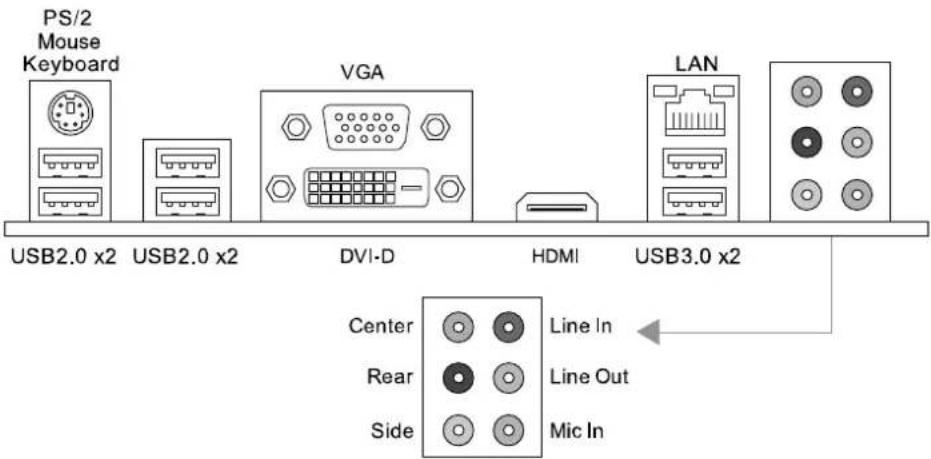
1.4 Rear Panel Connectors
text_image
PS/2 Mouse Keyboard USB2.0 x2 USB2.0 x2 VGA LAN DVI-D HDMI USB3.0 x2 Center Line In Rear Line Out Side Mic InNote1: HDMI, DVI-D & VGA ports only work with an Intel® integrated Graphics Processor.
Note2: Maximum resolution:
HDMI: 4096 x 2160 @24Hz, compliant with HDMI 1.4a
DVI: 1920 x 1200 @60Hz
VGA: 1920 x 1200 @60Hz
Note3: The mainboard supports three onboard display outputs at same time.
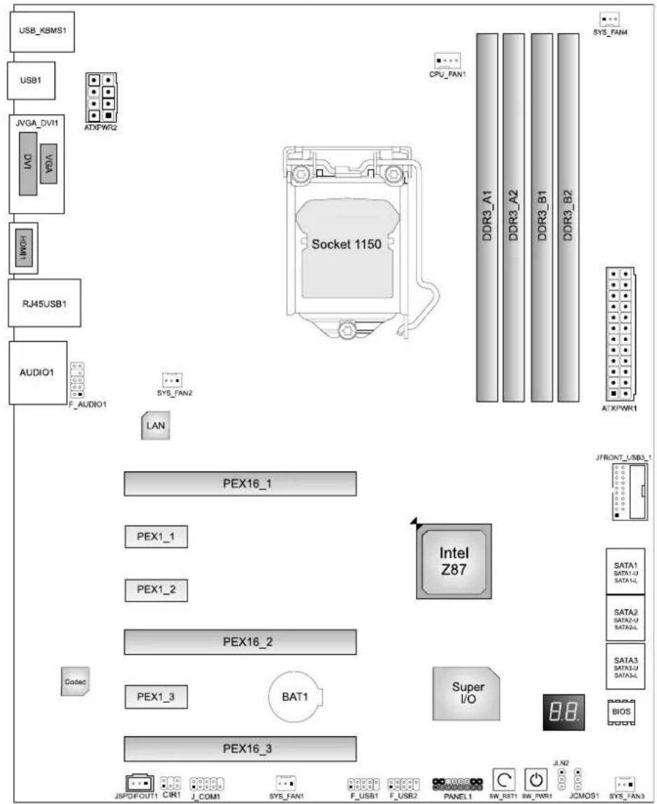
1.5 Motherboard Layout
flowchart
graph TD
    A["USB_KBMS1"] --> B["USB1"]
    B --> C["JVGA_DVI1"]
    C --> D["DAI"]
    D --> E["VGA"]
    E --> F["VMCI"]
    F --> G["RJ45USB1"]
    G --> H["AUDIO1"]
    H --> I["F_AUDIO1"]
    I --> J["SYS_FAN2"]
    J --> K["LAN"]
    K --> L["PEX16_1"]
    L --> M["PEX1_1"]
    M --> N["PEX1_2"]
    N --> O["PEX16_2"]
    O --> P["Codec"]
    P --> Q["PEX1_3"]
    Q --> R["BAT1"]
    R --> S["Super I/O"]
    S --> T["BIOS"]
    T --> U["PEX16_3"]
    U --> V["JSPDFOUT1 CIR1 J_COM1 SYS_FAN1 F_USB1 F_USB2 PANEL1 SN_RST1 SN_PWR1 JCMOS1 SYS_FAN3"]
    V --> W["JN2"]
    W --> X["SATA1 SATA1-U SATA2"]
    X --> Y["SATA2 SATA2-U SATA3"]
    Y --> Z["SATA3 SATA3-U SATA3"]
    Z --> AA["SATA3 SATA3-U SATA3"]
    AA --> AB["JFRONT_USB3_1"]
CHAPTER 2: HARDWARE INSTALLATION
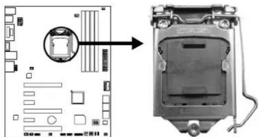
2.1 Install Central Processing Unit (CPU)
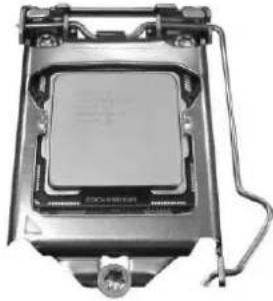
Step 1: Locate the CPU socket on the motherboard
natural_image
Diagram showing a computer motherboard with an open socket and cable connector (no text or symbols)Note1: Remove Pin Cap before installation, and make good preservation for future use. When the CPU is removed, cover the Pin Cap on the empty socket to ensure pin legs won't be damaged. Note2: The motherboard might equip with two different types of pin cap. Please refer below instruction to remove the pin cap.
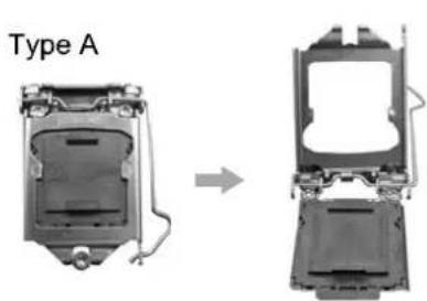
Step 2: Pull the socket locking lever out from the socket and then raise the lever up.
natural_image
Diagram showing a device labeled 'Type A' before and after assembly, with no visible text or symbols on the diagram itself.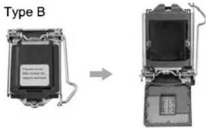
text_image
Type B Please have: This device for Nations hardwareStep 3: Remove the Pin Cap.
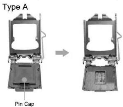
text_image
Type A Pin Cap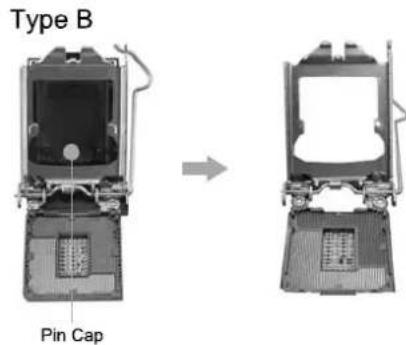
text_image
Type B Pin CapMotherboard Manual
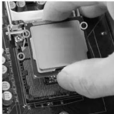
Step 4: Hold processor with your thumb and index fingers, oriented as shown. Align the notches with the socket. Lower the processor straight down without tilting or sliding the processor in the socket.
natural_image
Close-up of a hand pressing a CPU socket on a motherboard (no visible text or symbols)Note1: The LGA1155 CPU is not compatible with LGA 1150 socket. Do not install a LGA 1155 CPU on the LGA 1150 socket.
Note2: The CPU fits only in one correct orientation. Do not force the CPU into the socket to prevent damaging the CPU.
Step 5: Hold the CPU down firmly, and then lower the lever to locked position to complete the installation.
natural_image
Close-up of a metallic CPU socket with mounting bracket and wiring (no visible text or symbols)2.2 Install a Heatsink
Step 1: Place the CPU fan assembly on top of the installed CPU and make sure that the four fasteners match the motherboard holes. Orient the assembly and make the fan cable is closest to the CPU fan connector.
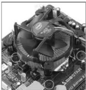
natural_image
Close-up of a computer motherboard with visible CPU socket and heatsink (no text or symbols)Step 2: Press down two fasteners at one time in a diagonal sequence to secure the CPU fan assembly in place. Ensure that all four fasteners are secured.
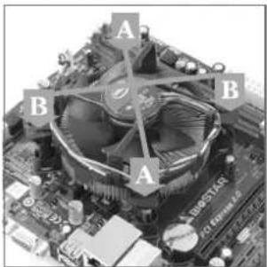
text_image
A B B A SABOSTAR X100000Note1: Do not forget to connect the CPU fan connector.
Note2: For proper installation, please kindly refer to the installation manual of your CPU heatsink.
2.3 Connect Cooling Fans
These fan headers support cooling-fans built in the computer. The fan cable and connector may be different according to the fan manufacturer.
CPU_FAN1: CPU Fan Header
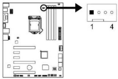
text_image
Diagram of a computer motherboard layout with labeled components and directional arrow indicating flow or movement.| Pin Assignment | |
| 1 | Ground |
| 2 | +12V |
| 3 | FAN RPM rate sense |
| 4 | Smart Fan Control (By Fan) |
SYS_FAN1/2/3/4: System Fan Header
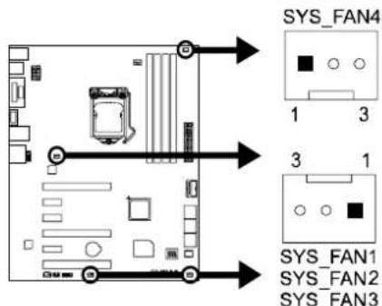
text_image
SYS_FAN4 1 3 3 1 SYS_FAN1 SYS_FAN2 SYS_FAN3| Pin Assignment | |
| 1 | Ground |
| 2 | +12V |
| 3 | FAN RPM rate sense |
Note: CPU_FAN1, SYS_FAN1/2/3/4 support 4-pin and 3-pin head connectors. When connecting with wires onto connectors, please note that the red wire is the positive and should be connected to pin#2, and the black wire is Ground and should be connected to pin#1(GND).
2.4 Install System Memory
DDR3 Modules
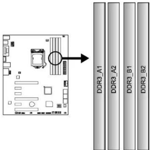
text_image
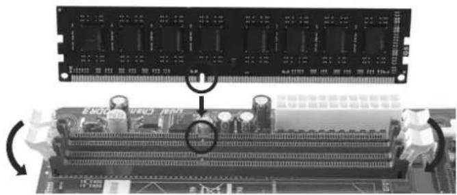
DDR3_A1 DDR3_A2 DDR3_B1 DDR3_B2Step 1: Unlock a DIMM slot by pressing the retaining clips outward. Align a DIMM on the slot such that the notch on the DIMM matches the break on the slot.
natural_image
Close-up of a computer RAM module with visible slots and circuit board (no text or symbols)Step 2: Insert the DIMM vertically and firmly into the slot until the retaining chip snap back in place and the DIMM is properly seated.
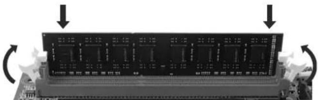
natural_image
Close-up of a dual-chip RAM module with multiple slots and control buttons, showing no visible text or symbols.Note: If the DIMM does not go in smoothly, do not force it. Pull it all the way out and try again.
Memory Capacity
| DIMM Socket Location | DDR3 Module | Total Memory Size |
| DDR3_A1 | 512MB/1GB/2GB/4GB/8GB | Max is 32GB. |
| DDR3_A2 | 512MB/1GB/2GB/4GB/8GB | |
| DDR3_B1 | 512MB/1GB/2GB/4GB/8GB | |
| DDR3_B2 | 512MB/1GB/2GB/4GB/8GB |
Dual Channel Memory Installation
Please refer to the following requirements to activate Dual Channel function: Install memory module of the same density in pairs, shown in the table.
| Dual Channel Status | DDR3_A1 DDR3 | A2 DDR3_B1 | DDR3_B2 | |
| Enabled | O | X | O | |
| Enabled | X | O | X | |
| Enabled | O | O | O |
(O means memory installed, X means memory not installed.)
Note: The DRAM bus width of the memory module must be the same (x8 or x16)
2.5 Expansion Slots
Install an Expansion Card
You can install your expansion card by following steps:
- Read the related expansion card's instruction document before install the expansion card into the computer.
- Remove your computer's chassis cover, screws and slot bracket from the computer.
- Place a card in the expansion slot and press down on the card until it is completely seated in the slot.
- Secure the card's metal bracket to the chassis back panel with a screw.
- Replace your computer's chassis cover.
- Power on the computer, if necessary, change BIOS settings for the expansion card.
- Install related driver for the expansion card.
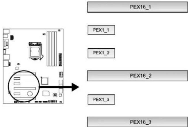
PEX16\_1/ PEX16\_2: PCI-Express Gen3 x16 (x8 / x8) (AMD CrossFireX) Slots
- PCI-Express 3.0 compliant.
- Maximum theoretical realized bandwidth of 16GB/s simultaneously per direction, for an aggregate of 32GB/s totally.
PEX16\_3: PCI-Express Gen2 x4 Slot
- PCI-Express 2.0 compliant.
- Maximum theoretical realized bandwidth of 2GB/s simultaneously per direction, for an aggregate of 4GB/s totally.
PEX1\_1/1\_2/1\_3: PCI-Express Gen2 x1 Slots
- PCI-Express 2.0 compliant.
- Data transfer bandwidth up to 500MB/s per direction; 1GB/s in total
flowchart
graph TD
    A["CPU socket"] --> B["PEX16_1"]
    A --> C["PEX1_1"]
    A --> D["PEX1_2"]
    A --> E["PEX16_2"]
    A --> F["PEX1_3"]
    A --> G["PEX16_3"]
Note: For more details about AMD CrossFireX, please visit below webpage. http://support.amd.com/us/Pages/AMDSupportHub.aspx
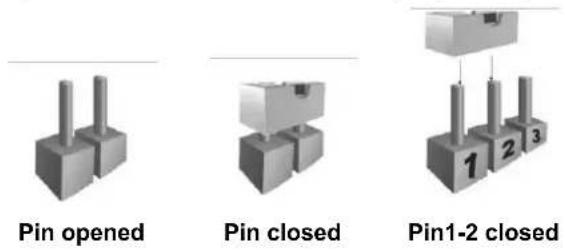
2.6 Jumper Setting
The illustration shows how to set up jumpers. When the jumper cap is placed on pins, the jumper is "close", if not, that means the jumper is "open".
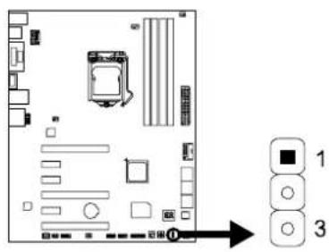
JCMOS1: Clear CMOS Jumper
Placing the jumper on pin2-3, it allows user to restore the BIOS safe setting and the CMOS data. Please carefully follow the procedures to avoid damaging the motherboard.
text_image
Diagram of a computer motherboard layout with labeled components and directional arrow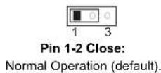
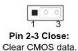
- Remove AC power line.
- Set the jumper to "Pin 2-3 close".
- Wait for five seconds.
- Set the jumper to "Pin 1-2 close".
- Power on the AC.
- Load Optimal Defaults and save settings in CMOS.
2.7 Headers & Connectors
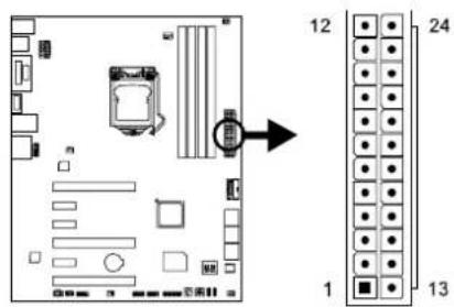
ATXPWR1: ATX Power Source Connector
This connector allows user to connect an ATX 24-pin power supply. Make sure to find the proper orientation before plugging the connector.
text_image
Diagram of a computer motherboard with labeled components and an arrow pointing to component 12| Pin | Assignment | Pin | Assignment | |
| 13 | +3.3V | 1 | +3.3V | |
| 14 | -12V | 2 | +3.3V | |
| 15 | Ground | 3 | Ground | |
| 16 | PS_ON | 4 | +5V | |
| 17 | Ground | 5 | Ground | |
| 18 | Ground | 6 | +5V | |
| 19 | Ground | 7 | Ground | |
| 20 | NC | 8 | PW_OK | |
| 21 | +5V | 9 | Standby | Voltage+5V |
| 22 | +5V | 10 | +12V | |
| 23 | +5V | 11 | +12V | |
| 24 | Ground | 12 | +3.3V | |
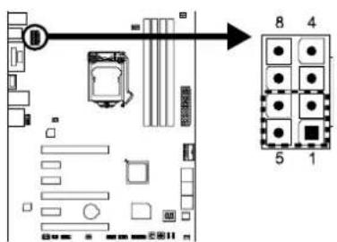
ATXPWR2: ATX Power Source Connector
The connector provides +12V to the CPU power circuit. If the CPU power plug is 4-pin, please plug it into Pin 1-2-5-6 of ATXPWR2.
text_image
Floor plan diagram with room labels and numbered compartments, showing layout and directional arrow| Pin | Assignment |
| 1 | +12V |
| 2 | +12V |
| 3 | +12V |
| 4 | +12V |
| 5 | Ground |
| 6 | Ground |
| 7 | Ground |
| 8 | Ground |
Note1: Before you power on the system, please make sure that both ATXPWR1 and ATXPWR2 connectors have been plugged-in.
Note2: Insufficient power supplied to the system may result in instability or the peripherals not functioning properly. Use of a PSU with a higher power output is recommended when configuring a system with more power-consuming devices.
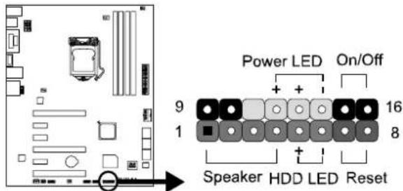
PANEL1: Front Panel Header
This 16-pin header includes Power-on, Reset, HDD LED, Power LED, and speaker connection. It allows user to connect the PC case's front panel switch functions.
text_image
Power LED On/Off 9 16 1 8 Speaker HDD LED Reset| Pin | Assignment | Function | Pin Assignment | Function | |||
| 1 | +5V | 9 | N/ASpeakerConnector N/A | N/A | |||
| 2 | N/A | 10 | |||||
| 3 | N/A | 11 | |||||
| 4 | Speaker | 12 Power LED (+) | Power LED | ||||
| 5 | HDD LED (+) | 13 Power LED | Bar(+) driveLED | ||||
| 6 | HDD LED (-) | 14 Power LED (-) | |||||
| 7 | Ground | 15 | Power buttonReset button | Power-on button | |||
| 8 | Reset control | 16 Ground | |||||
SATA1\~SATA3: Serial ATA 6.0 Gb/s Connectors
These connectors connect to SATA hard disk drives via SATA cables.
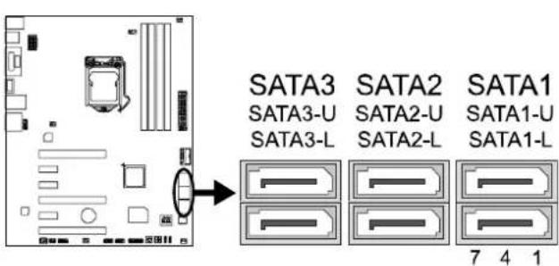
text_image
SATA3 SATA2 SATA1 SATA3-U SATA2-U SATA1-U SATA3-L SATA2-L SATA1-L 7 4 1| Pin | Assignment |
| 1 | Ground |
| 2 | TX+ |
| 3 | TX- |
| 4 | Ground |
| 5 | RX- |
| 6 | RX+ |
| 7 | Ground |
JFRONT\_USB3\_1: Header for USB 3.0 Ports at Front Panel
This header allows user to add additional USB ports on the PC front panel, and also can be connected with a wide range of external peripherals.
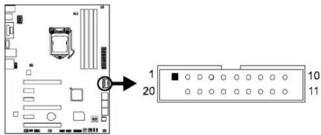
text_image
1 20 10 11| Pin | Assignment | Pin | Assignment | |
| 1 | VBUS0 | 11 | D2+ | |
| 2 | SSRX1- | 12 | D2- | |
| 3 | SSRX1+ | 13 | Ground | |
| 4 | Ground | 14 | SSTX2+ | |
| 5 | SSTX1- | 15 | SSTX2- | |
| 6 | SSTX1+ | 16 | Ground | |
| 7 | Ground | 17 | S$RX2+ | |
| 8 | D1- | 18 | SSRX2- | |
| 9 | D1+ | 19 | VBUS1 | |
| 10 | ID | 20 | Key | |
F\_USB1/2: Header for USB 2.0 Ports at Front Panel
This header allows user to add additional USB ports on the PC front panel, and also can be connected with a wide range of external peripherals.
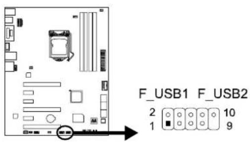
text_image
F_USB1 F_USB2 2 10 1 9| Pin Assignment | |
| 1 | +5V (fused) |
| 2 | +5V (fused) |
| 3 | USB- |
| 4 | USB- |
| 5 | USB+ |
| 6 | USB+ |
| 7 | Ground |
| 8 | Ground |
| 9 | NC |
| 10 Key | |
F\_AUDIO1: Front Panel Audio Header
This header allows user to connect the chassis-mount front panel audio I/O which supports HD and AC'97 audio standards.
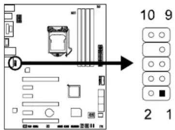
text_image
10 9 2 1| HD Audio AC'97 | ||||
| Pin | Assignment | Pin | Assignment | |
| 1 Mic Left in 1 Mic In | ||||
| 2 | Ground | 2 | Ground | |
| 3 Mic Right in 3 Mic Power | ||||
| 4 | GPIO | 4 | Audio | Power |
| 5 Right line in 5 RT Line Out | ||||
| 6 Jack Sense 6 RT Line Out | ||||
| 7 | Front | Sense | 7 | Reserved |
| 8 | Key | 8 | Key | |
| 9 Left line in 9 LFT Line Out | ||||
| 10 Jack Sense 10 LFT Line Out | ||||
Note1: It is recommended that you connect a high-definition front panel audio module to this connector to avail of the motherboard's high definition audio capability. Note2: Please try to disable the "Front Panel Jack Detection" if you want to use an AC'97 front audio output cable. The function can be found via O.S. Audio Utility.
JSPDIFOUT1: Digital Audio-out Connector
The connector is for connecting the S/PDIF output bracket.
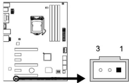
text_image
Diagram of a computer motherboard with labeled components and an arrow pointing to component 3 and component 1| Pin Assignment | |
| 1 | +5V |
| 2 | SPDIF_OUT |
| 3 | Ground |
J\_COM1: Serial Port Header
The motherboard has a serial port header for connecting RS-232 Port.
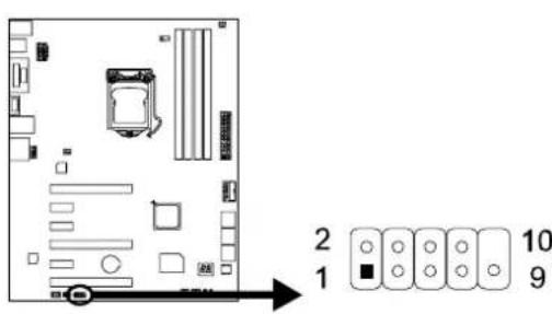
text_image
2 1 10 9| Pin | Assignment |
| 1 | Carrier detect |
| 2 | Received data |
| 3 | Transmitted data |
| 4 | Data terminal |
| 5 | Signal ground |
| 6 Data set ready | |
| 7 Request to send | |
| 8 | Clear to send |
| 9 | Ring indicator |
| 10 | NC |
CIR1: Consumer IR Header
This header is for infrared remote control and communication.
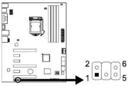
text_image
Diagram of a computer motherboard layout with numbered components and directional arrow indicating orientation| Pin Assignment | |
| 1 IrDA serial input | |
| 2 | Ground |
| 3 | Ground |
| 4 | Key |
| 5 IrDA serial output | |
| 6 | IR Power |
2.8 Smart Switches & Indicators
On-Board Buttons
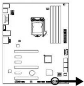
text_image
Diagram of a computer motherboard layout with labeled components and directional arrow indicating orientation
SW_PWR1:
This is an on-board Power Switch button.
SW_RST1:
This is an on-board Reset button.
BIOS POST Code/CPU Temperature Indicator
This indicator will show POST code while booting. After the booting sequence, it will show current CPU temperature in Celsius. Please refer to Chapter 4.3 for all the BIOS POST codes.
natural_image
Top-down schematic of a computer motherboard layout with slots, buttons, and a mouse (no text or labels)
CHAPTER 3: UEFI BIOS & SOFTWARE
3.1 UEFI BIOS Setup
- The BIOS Setup program can be used to view and change the BIOS settings for the computer. The BIOS Setup program is accessed by pressing the
key after the Power-On Self-Test (POST) memory test begins and before the operating system boot begins. - For further information of setting up the UEFI BIOS, please refer to the UEFI BIOS Manual in the Setup DVD.
3.2 BIOS Update
The BIOS can be updated using either of the following utilities:
- BIOSTAR BIOS Flasher: Using this utility, the BIOS can be updated from a file on a hard disk, a USB drive (a flash drive or a USB hard drive), or a CD-ROM.
- BIOSTAR BIOS Update Utility: It enables automated updating while in the Windows environment. Using this utility, the BIOS can be updated from a file on a hard disk, a USB drive (a flash drive or a USB hard drive), or a CD-ROM, or from the file location on the Web.
BIOSTAR BIOS Flasher
Note1: This utility only allows storage device with FAT32/16 format and single partition.
Note2: Shutting down or resetting the system while updating the BIOS will lead to system boot failure.
Updating BIOS with BIOSTAR BIOS Flasher
- Go to the website to download the latest BIOS file for the motherboard.
- Then, copy and save the BIOS file into a USB flash (pen) drive.
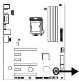
- Insert the USB pen drive that contains the BIOS file to the USB port.
-
Power on or reset the computer and then press
during the POST process. -
After entering the POST screen, the BIOS-FLASHER utility pops out. Choose [fs0] to search for the BIOS file.
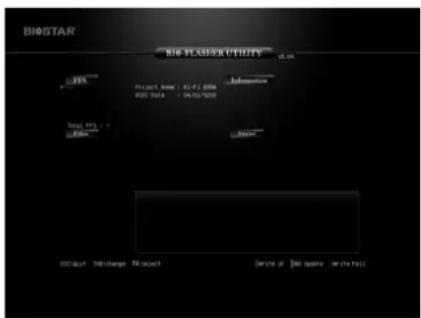
text_image
BIOSTAR BIO BIASER UTILITY 12:00 Project Name: 01-07/2006 ISSN Date: 04/03/2009 Total grant: Exhibit No change No amount Service or Buy option or the pass- Select the proper BIOS file, and a message asking if you are sure to flash the BIOS file. Click Yes to start updating BIOS.
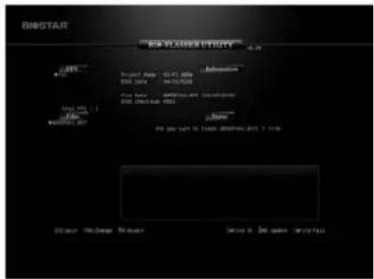
text_image
BIGSTAR BIG STAR Utility Project Name: 42-01-2009 SIPID NAME: 04757500 File NAME: 0000000000000000000000000000000000000000000000000000000000000000 System ID: 1.1 System Status: 1.1 System Status: 1.1 System Status: 1.1 System Status: 1.1 System Status: 1.1 System Status: 1.1 System Status: 1.1 System Status: 1.1 System Status: 1.1 System Status: 1.1 System Status: 1.1 System Status: 1.1 System Status: 1. System Status: 1. System Status: 1. System Status: 1. System Status: 1. System Status: 1. System Status: 1. System Status: 1. System Status: 1. System Status: 1. System Status: 1. System Status: 1. System Status: 1. System Status: 1. System Status: 1. System Status: 1. System Status: 1. System Status: System Status: System Status: System Status: System Status: System Status: System Status: System Status: System Status: System Status: System Status: System Status: System Status: System Status: System Status: System Status: System Status: System Status: System Status: System Status: System Status: System Status: System Status: System Status: System Status: System Status: USE / Purchase Number Store & Delivered Summary- A dialog pops out after BIOS flash is completed, asking you to restart the system. Press the [Y] key to restart system.
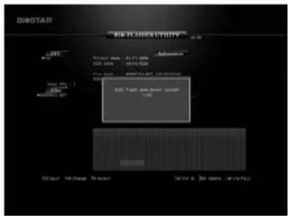
text_image
BIOSSTAR BIOS MAXIMETER V. 20 V1:150 MHz 30.000 MHz V2:150 MHz 30.000 MHz V3:150 MHz 30.000 MHz V4:150 MHz 30.000 MHz V5:150 MHz 30.000 MHz V6:150 MHz 30.000 MHz V7:150 MHz 30.000 MHz V8:150 MHz 30.000 MHz V9:150 MHz 30.000 MHz V10:150 MHz 30.000 MHz V11:150 MHz 30.000 MHz V12:150 MHz 30.000 MHz V13:150 MHz 30.000 MHz V14:150 MHz 30.000 MHz V15:150 MHz 30.000 MHz V16:150 MHz 30.000 MHz V17:150 MHz 30.000 MHz V18:150 MHz 30.000 MHz V19:150 MHz 30.000 MHz V20:150 MHz 30.000 MHz V21:150 MHz 30.000 MHz V22:150 MHz 30.000 MHz V23:150 MHz 30.000 MHz V24:150 MHz 30.000 MHz V25:150 MHz 30.000 MHz V26:150 MHz 30.000 MHz V27:150 MHz 30.000 MHz V28:150 MHz 30.000 MHz V29:150 MHz 30.000 MHz V30:150 MHz 30.000 MHz V31:150 MHz 30.000 MHz V32:150 MHz 30.000 MHz V33:150 MHz 30.000 MHz V34:150 MHz 30.000 MHz V35:150 MHz 30.000 MHz V36:150 MHz 30.000 MHz V37:150 MHz 30.000 MHz V38:150 MHz 30.000 MHz V39:150 MHz 30.000 MHz V40:150 MHz 30.000 MHz V41:150 MHz 30.000 MHz V42:150 MHz 30.000 MHz V43:150 MHz 30.000 MHz V44:150 MHz 30.000 MHz V45:150 MHz 30.000 MHz V46:150 MHz 30.000 MHz V47:150 MHz 30.000 MHz V48:150 MHz 30.000 MHz V49:150 MHz 30.000 MHz V50:15- While the system boots up and the full screen logo shows up, press
key to enter BIOS setup. After entering the BIOS setup, please go to the Save & Exit, using the Restore Defaults function to load Optimized Defaults, and select Save Changes and Reset to restart the computer. Then, the BIOS Update is completed.
BIOS Update Utility (through the Internet)
- Installing BIOS Update Utility from the DVD Driver.
-
Please make sure the system is connected to the internet before using this function.
-
Launch BIOS Update Utility and click the Online Update button on the main screen.
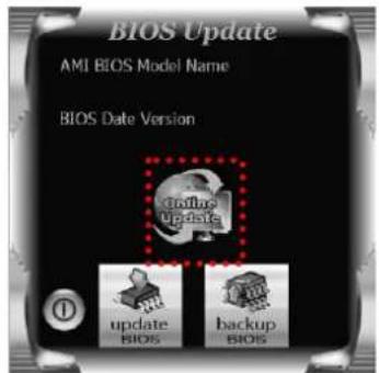
text_image
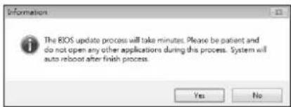
BIOS Update AMI BIOS Model Name BIOS Date Version Update Bios backup Bios- An open dialog will show up to request your agreement to start the BIOS update. Click Yes to start the online update procedure.
- If there is a new BIOS version, the utility will ask you to download it. Click Yes to proceed.
- After the download is completed, you will be asked to program (update) the BIOS or not. Click Yes to proceed.
- After the updating process is finished, you will be asked you to reboot the system. Click OK to reboot.
text_image
Information The BIOS update process will take minutes. Please be patient and do not open any other applications during this process. System will auto reboot after finish process. Yes No
text_image
Do you want to download H67BR802.8ST BIOS via Internet ? Yes No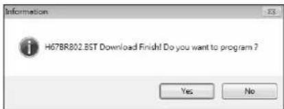
text_image
H67BR802.BST Download Finish! Do you want to program ? Yes No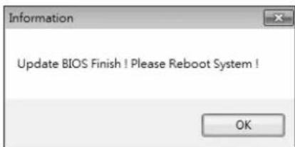
text_image
Information Update BIOS Finish ! Please Reboot System ! OK- While the system boots up and the full screen logo shows up, press
key to enter BIOS setup. After entering the BIOS setup, please go to the Save & Exit, using the Restore Defaults function to load Optimized Defaults, and select Save Changes and Reset to restart the computer. Then, the BIOS Update is completed.
BIOS Update Utility (through a BIOS file)
- Installing BIOS Update Utility from the DVD Driver.
-
Download the proper BIOS from http://www.biostar.com.tw/
-
Launch BIOS Update Utility and click the Update BIOS button on the main screen.
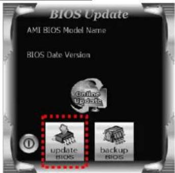
text_image
BIOS Update AMI BIOS Model Name BIOS Date Version Update Bios backup BiosMotherboard Manual
- A warning message will show up to request your agreement to start the BIOS update. Click OK to start the update procedure.
- Choose the location for your BIOS file in the system. Please select the proper BIOS file, and then click on Open. It will take several minutes, please be patient.
- After the BIOS Update process is finished, click on OK to reboot the system.

text_image
BIOS Update Message The BIOS update process will take minutes. Please be patient and do not open any other applications during this process. System will auto reboot after finish process. OK Cancel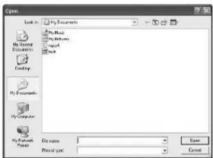
text_image
Open Look in: My Documents My Book My History Report Next My Document My Computer My Network File name: Files of type: Open Cancel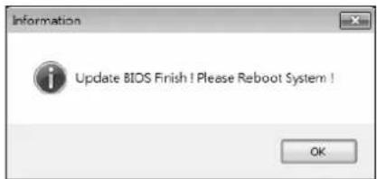
text_image
Information Update BIOS Finish ! Please Reboot System ! OK- While the system boots up and the full screen logo shows up, press
key to enter BIOS setup.
After entering the BIOS setup, please go to the Save & Exit, using the Restore Defaults function to load Optimized Defaults, and select Save Changes and Reset to restart the computer. Then, the BIOS Update is completed.
Backup BIOS
Click the Backup BIOS button on the main screen for the backup of BIOS, and select a proper location for your backup BIOS file in the system, and click Save.
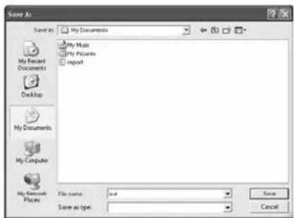
text_image
Save As My Documents My Music My Pictures Import My Recent Documents Desktop My Documents My Computer My Network Places File name: not Save as type Save as type Cancel3.3 Software
Installing Software
- Insert the Setup DVD to the optical drive. The driver installation program would appear if the Auto-run function has been enabled.
- Select Software Installation, and then click on the respective software title.
- Follow the on-screen instructions to complete the installation.
Launching Software
After the installation process is completed, you will see the software icon showing on the desktop. Double-click the icon to launch it.
Note1: All the information and content about following software are subject to be changed without notice. For better performance, the software is being continuously updated. Note2: The information and pictures described below are for your reference only. The actual information and settings on board may be slightly different from this manual.
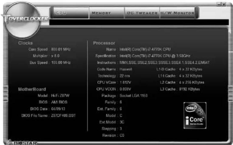
TOverclocker
TOverclocker presents a simple Windows-based system performance enhancement and manageability utility. It features several powerful and easy to use tools such as Overclocking for enhancing system performance, also for special enhancement on CPU and Memory. Smart-Fan management and PC health are for monitoring system status. This utility also allows you to make overclocking profiles saving unlimitedly, and pre-set OC modes are for easy OC. (The screenshots below are for reference only)
text_image
CPU MEMORY PC-TWEAKER H/W MONITOR OVERCLOCKER Clocks Core Speed: 800.01 MHz Multiplier: x 8.0 Bus Speed: 100.00 MHz MotherBoard Model: Hi-Fi Z87W BIOS: AMI BIOS BIOS Date: 04/09/13 BIOS File Name: Z87DF409.BST Processor Name: Intel(R) Core(TM) i7-4770K CPU Specification: Intel(R) Core(TM) i7-4770K CPU @ 3.50GHz Instructions: MMX.SSE.SSE2.SSE3.SSE3.SSE4.1.SSE4.2.EM64T Code Name: Haskell L1-D Cache: 4 x 32 KBytes Technology: 22 nm L1-I Cache: 4 x 32 KBytes CPU VCore: 1.812V L2 Cache: 4 x 256 KBytes CPU VCCIN: 0.008V LJ Cache: 8192 KBytes Package: Socket LGA 1150 Family: 6 Ext. Family: 6 Model: C Ext Model: 3C Stepping: 3 Revision: CO
The CPU tab provides information on the CPU and motherboard.
The Memory tab provides information on the memory module(s).
You can select memory module on a specific slot to see its information.
Motherboard Manual

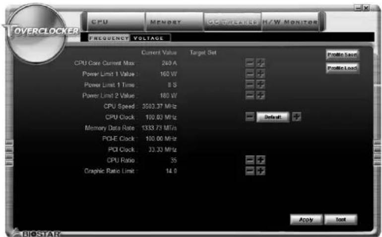
The OC Tweaker tab allows you to save or load the OC setting profiles, frequency and voltage settings.
text_image
CPU MENDEY GO/TWEAVED H/W MONITOR FREQUENCY VOLTAGE Current Value Target Set Profile Scan Profile Load CPU Core Current Max 240 A Power Limit 1 Value 160 W Power Limit 1 Time 8 S Power Limit 2 Value 180 W CPU Speed 3503.37 MHz CPU Clock 100.03 MHz Memory Data Rate 1333.73 MHz PCI-E Clock 100.00 MHz PCI Clock 33.33 MHz CPU Ratio 35 Graphic Ratio Limit 14.0 Default + Apply Text BIOSTAR
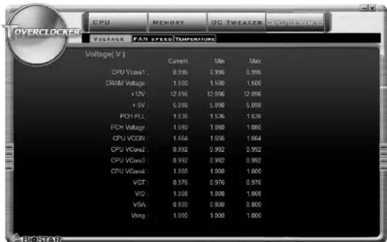
The HW Monitor tab allows you to monitor hardware voltage, fanperature. You can also set CPU Smart Fan function in this tab.
text_image
OVERCLOCKER CPU MEMORY PG TWEAKER RAW MOLTAGE VOLTAGE FAN SPEED TEMPERATURE Voltage(V) Current Min Max CPU VCore1: 0.996 0.996 0.996 DRAM Voltage: 1.500 1.500 1.500 +12V: 12.096 12.096 12.096 +5V: 5.096 5.098 5.098 PCH PLL: 1.536 1.536 1.536 PCH Voltage: 1.080 1.080 1.080 CPU VCCIN: 1.664 1.664 1.664 CPU VCore2: 0.992 0.992 0.992 CPU VCore3: 0.992 0.992 0.992 CPU VCore4: 1.000 1.000 1.000 VGT: 0.976 0.976 0.976 VIO: 1.008 1.008 1.008 VSA: 0.800 0.800 0.800 Vring: 1.000 1.000 1.000Note1: Not all types of CPU perform above overclock setting ideally; the difference will be based on the selected CPU model.
Note2: Overclock is an optional process, but not a "must-do" process; it is not recommended for inexperienced users. Therefore, we will not be responsible for any hardware damage which may be caused by overclocking. We also would not guarantee any overclocking performance.
Note3: Press TOVERCLOCKER logo, it will display information about manufacturer and software version. You can update latest version by clicking the "Live Update" button.
BIOScreen Utility
This utility allows you to personalize your boot logo easily. You can choose BMP as your boot logo so as to customize your computer.

text_image
800 x 600 BIOSTAR® WWW.B.OSTAR.COM.TW Load Image Transform Update Bios Close AboutPlease follow the step-by-step instructions below to update boot logo:
- Load Image : Choose the picture as the boot logo.
● Transform : Transform the picture for BIOS and preview the result. - Update Bios : Write the picture to BIOS Memory to complete the update.
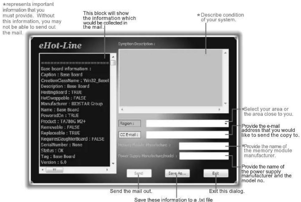
eHot-Line
eHot-Line is a convenient utility that helps you to contact with our Tech-Support system. This utility will collect the system information which is useful for analyzing the problem you may have encountered, and then send these information to our tech-support department to help you fix the problem.
Note: Before you use this utility, please set Outlook Express as your default e-mail client application program.
text_image
eHot-Line Base board information : Caption : Base Board CreationClassName : Win32_Basel Description : Base Board HostingsBoard : TRUE HotSwappable : FALSE Manufacturer : BIDSTAR Group Name : Base Board PoweredOn : TRUE Product : TA780G M2+ Removable : FALSE Replaceable : TRUE RequiresDaughterBoard : FALSE SerialNumber : None Status : OK Tag : Base Board Version : 5.0 This block will show the information which would be collected in the mail. Symptom Description : Region : CC E-mail : *Describe condition of your system. *Select your area or the area close to you. Provide the e-mail address that you would like to send the copy to. *Provide the name of the memory module manufacturer. Power Supply Manufacture/model : Send : Save As ... Exit Send the mail out. Save these information to a .txt file Exit this dialog.After filling up this information, click "Send" to send the mail out. A warning dialog would appear asking for your confirmation; click "Send" to confirm or "Do Not Send" to cancel.
If you want to save this information to a .txt file, click "Save As..." and then you will see a saving dialog appears asking you to enter file name.

text_image
Outlook Express A program is attempting to send the following e-mail message on your behalf: To: support@biostarusa.com,XXX@xxx.xx.xx.xx.xx Subject: TP35D2-A7 (P35BAC05 BS) report! Would you like to send the message? Send Do Not SendEnter the file name and then click "Save". Your system information will be saved to a .txt file.
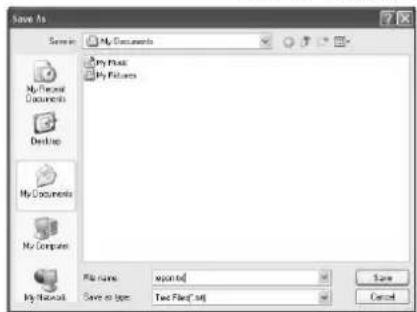
text_image
Save As Scene: My Documents My Files My Pictures My Documents My Computer My Mail File name: exported Save as type: Two Files*.txt Save CancelOpen the saved .txt file, you will see your system information including motherboard/BIOS/CPU/video/device/OS information. This information is also concluded in the sent mail.
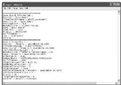
text_image
File Name File Path: New York New Book Information Current: New York Current: New York - 1007 Russian Current: New York - 1006 Russian Current: New York - 1005 Russian Current: New York - 1004 Russian Current: New York - 1003 Russian Current: New York - 1002 Russian Current: New York - 1001 Russian Current: New York - 1000 Russian Current: New York - 1000 Russian Current: New York - 1000 Russian Current: New York - 1000 Russian Current: New York - 1000 Russian Current: New York - 1000 Russian Current: New York - 1000 Russian Current: New York - 1000 Russian Current: New York - 1000 Russian Current: Current: New York - 1000 Russian Current: New York - 1000 Russian Current: New York - 1000 Russian Current: New York - 1000 Russian Current: New York - 1000 Russian Current: New York - 1000 Russian Current: New York - 1000 Russian Current: New York - 1000 Russian Current: New Yolkswagen - 1.5 Current: New York - 1.5 Current: New York - 1.5 Current: New York - 1.5 Current: New York - 1.5 Current: New York - 1.5 Current: New York - 1.5 Current: New York - 1.5 Current: New York - 1.5 Current: New York - 1.5 Current: New York - 1.5 Current: New Yolkswagen - 1.5 Current: New York - 1.5 Current: New York - 1.5 Current: New York - 1.5 Current: New York - 1.5 Current: New York - 1.5 Current: New York - 1.5 Current: New York - 1.5 Current: New York - 1.5 Current: New York - 2.5 Current: New York - 2.5 Current: New York - 2.5 Current: New York - 2.5 Current: New York - 2.5 Current: New York - 2.5 Current: New York - 2.5 Current: New York - 2.5 Current: New York - 2.5 Current: New York - 2.5 Current: New York - 3.5 Current: New York - 3.5 Current: New York - 3.5 Current: New York - 3.5 Current: New York - 3.5 Current: New York - 3.5 Current: New York - 3.5 Current: New York - 3.5 Current: New York - 3.5 Current: New York - 3.5 Current: New York - 4.5 Current: New York - 4.5 Current: New York - 4.5 Current: New York - 4.5 Current: New York - 4.5 Current: New York - 4.5 Current: New York - 4.5 Current: New York - 4.5 Current: New York - 4.5 Current: New York - 4.5 Current: New York - 5.5 Current: New York - 5.5 Current: New York - 5.5 Current: New York - 5.5 Current: New York - 5.5 Current: New York - 5.5 Current: New York - 5.5 Current: New York - 6.5 Current: New York - 6.5 Current: New York - 6.5 Current: New York - 6.5 Current: New York - 6.5 Current: New York - 6.5 Current: New York - 6.5 Current: New York - 6.5 Current: New York - 6.5Note1: We will not share customer's data with any other third parties, so please feel free to provide your system information while using eHot-Line service.
Note2: If you are not using Outlook Express as your default e-mail client application, you may need to save the system information to a .txt file and send the file to our tech support with other e-mail application. Go to the following website http://www.biostar.com.tw/app/en/about/contact.php for getting our contact information.
Smart EAR 3D
Hi-Fi 3D Audio Requirements:
- A chassis with front audio output jacks
- An earphone or a headphone
- Speakers
- Windows 7 or Windows 8 operation system
Installation Guide:
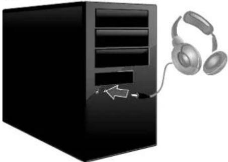
- Make sure the front audio cable of the chassis connected to the front audio header of the motherboard properly.
- Install the Smart Ear 3D Utility from the driver DVD.
- Connect the earphone or headphone to the front audio jack of the chassis for Smart Gain and 3D Sound Field functions.
natural_image
Illustration of a desktop computer tower with headphones connected to a mouse (no text or symbols)- Connect the speakers to center, rear, side and line out ports of rear panel for Smart PREAMP function.
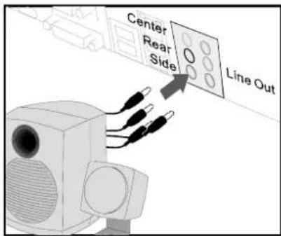
text_image
Center Rear Side Line OutNote: If you want to use an AC'97 front audio output cable, please disable the "Front Panel Jack Detection" setting. This setting can be found via O.S. Audio Utility.
Smart EAR 3D Utility:
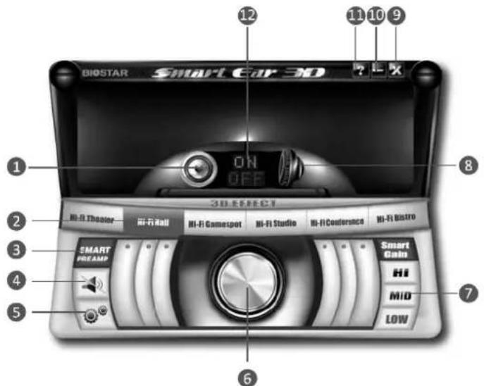
text_image
12 11 10 9 BIOSTAR Smart Car 3D ? I E X ON OFF 3D SELECT Hi-Fi Theater Hi-Fi Hall Hi-Fi Gamespot Hi-Fi Studio Hi-Fi Conference Hi-Fi Bistro SMART PREAM Smart Gain Hi MID LOW 6- Rear Panel Audio Output Indicator: It displays a blue light when the audio output is from rear panel ports.
- 3D Sound Field Button: There are six sound environment options for achieving realistic listening experience. It displays a blue light when the 3D Sound Field is enabled.
- Smart PREAMP Button: Click this switch to turn on or off the Smart PREAMP function.
- Mute Button: To disable system sound
- Control Button: It allows you to set utility preference.
- Volume Control Knob: The volume can be finely adjusted by turning the knob either clockwise or anti-clockwise to increase or decrease system volume accordingly.
- Headphone Hi/Mid/Low Gain Switch: It allows you to select headphone gain settings or you can let the software auto adjust headphone gain setting appropriate for your headphones. The Smart Gain function will be enabled when the 3D Sound Field Button is turned on.
- Front Panel Audio Output Indicator: It displays a blue light when the audio output is from front panel port.
- Exit Button: Exit the application
- Minimize Button: Minimize the application window to the taskbar
- Information Button: Get information of the application
- Smart PREAMP or Smart Gain ON/OFF Indicator: When the Rear Panel Audio Output Indicator is lit, it shows Smart PREAMP on/off status. When the Front Panel Audio Output Indicator is lit, it shows Smart Gain on/off status.
Note1: The 3D Sound Field function is only for front panel audio output.
Note2: The Smart PREAMP function is only for rear panel audio output.
Note3: When both rear and front panels are connected with audio devices, the default audio output is from front panel.
Multi Channels Calibration (MCC)
Multi Channels Calibration (MCC) can transform any room into the ideal listening environment. With Multi Channels Calibration (MCC), audio performance is automatically calibrated according to the dimensions of your room.
Take a note of following precautions before you start the calibration.
- Do not connect or disconnect the speaker setup microphone and speakers during the calibration.
- Do not stand between the speakers and microphone, and avoid obstacles blocking the path between speakers and microphone.
- Turn off all media players and do not adjust any audio settings (ex. volume or mute) in your operating system.
- MCC software is only supported by Windows 7/8 and BIOSTAR Hi-Fi series motherboards.
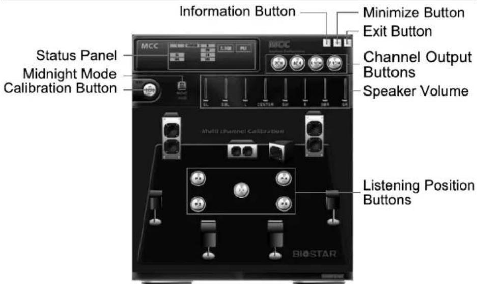
text_image
Information Button Minimize Button Exit Button Status Panel Midnight Mode Calibration Button MCC Multi channel Calibration Channel Output Buttons Speaker Volume Listening Position Buttons BIOSTAR● Status Panel: Show the information of speakers and listening positions.
- Midnight Mode: Turn on this function will let you enjoy a movie quietly without compromising sound qualities, surround effects and dialogue clarity.
● Calibration Button: Start or stop the calibration.
● Channel Output Buttons: Select the channel output (2/4/5.1/7.1-channel)
● Listening Position Buttons: It allows you setup five listening positions.
Speaker Volume: Show each speaker's volume.
● Information Button: Get information of the application.
- Minimize Button: Minimize the application window to the taskbar.
- Exit Button: Exit the application.
Start the Calibration:
Step 1:
Install and launch Multi Channels Calibration software
Step 2:
Arrange and connect the speakers in your room.
Step 3:
Select the channel output (2/4/5.1/7.1-channel) for the speak configuration.
Step 4:
Place the speaker setup microphone at ear height of a seated listener in your room and connection it to Mic In jack.
Note: To setup 5.1-channel for a motherboard with 3 audio jacks, please connect the speaker setup microphone to front panel Mic-In.
Step 5:
Select your preferred listening position and click the "Listening Position Button".
Step 6:
Click the "Calibration Button". You can see a notice window then click "Next" to start the calibration. The test tone will be played through each speakers and it will take 2-3 minutes to process the calibration. Please make the room as quiet as possible at the meantime.
Step 7:
After completing calibration, you will see a finish window then click "OK" to exit this calibration.
Audio Ports:
For the definition of each audio port, please refer to the table below:
The 2/4/5.1-channel configuration for 3 audio jacks
| Port 2-channel 4-channel 5.1 channel | |
| Blue Line In Rear Speaker Out Rear Speaker Out | |
| Green Line Out Front Speaker Out Front Speaker Out | |
| Pink Mic In Mic In Center/Subwoofer Out |
The 2/4/5.1/7.1-channel configuration for 6 audio jacks
| Port 2-channel 4-channel 5.1 channel 7.1 channel | ||||
| Blue Line In Line In | Line In | Line In | ||
| Green | Line Out | Front Speaker Out | Front Speaker Out | Front Speaker Out |
| Pink Mic In Mic In Mic In | Mic In | |||
| Orange | -- | -- | Center/Subwoofer Out | Center/Subwoofer Out |
| Black | N/A | Rear Speaker Out | Rear Speaker Out | Rear Speaker Out |
| Grey | -- | -- | -- | Side Speaker Out |
Note: Green, Orange, Black and Grey jacks are only for audio outputs.
Smart Connect Technology
Intel® Smart Connect Technology is designed to update programs by periodically waking your computer from sleep/standby mode for a short time. This function works with applications that automatically get their data from the Internet.
System Requirement:
- Intel Smart Connect Technology enabled in BIOS Setup
- Set the "ACPI Sleep State" to S3 in BIOS Setup.
● Windows 7 and Windows 8
● Normal internet connection
Configuring Intel Smart Connect Technology
Step 1: After installing the operating system and motherboard drivers, install the Intel Smart Connect Technology application. Restart your computer when completed.
Step 2: Click on start menu and input "regedit" in the search bar. Press enter to open the registry editor. Look for the following directory in the registry editor: Computer\HKEY_LOCAL_MACHINE\SOFTWARE\Intel\Intel Smart Connect Technology Right-click on Intel Smart Connect Technology and select New > Key. Type "OEM".
Note: Intel Smart Connect Technology is for S3 mode only. During the updating process, the monitor will not light up and no sound will be output from the speaker.
Step 3: As shown in the screenshot below, right-click on OEM, select New > Multi-String Value, and type "WhiteList". Double-click WhiteList and type the application name to be added in Edit Multi-String. For example, to add Microsoft Live Mail, type "w1mail.exe". Restart your computer when completed.
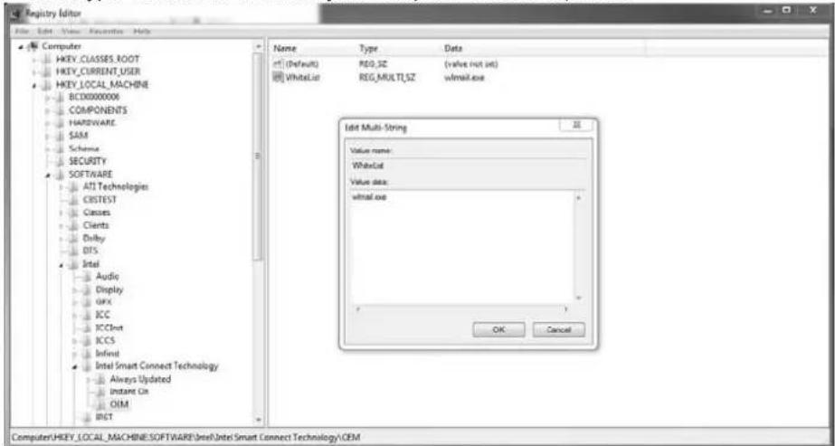
text_image
Registry Editor File Edit View Favorites Help Computer HKEY_CLASSES_ROOT HKEY_CURRENT_USER HKEY_LOCAL_MACHINE BCD00000006 COMPONENTS HARDWARE SAM Scheme SECURITY SOFTWARE ATI Technologies CRISTEST Classes Clients Delay DFS Intel Audio Display GFX RCC RCCout RCCS Infinit Intel Smart Connect Technology Always Updated Instant On OEM RIGT Name Type Data (Default) REG_SZ (value not set) WhiteList REG_MULTI_SZ wmail.exe Edit Multi-String Value name: WhiteList Value data: wmail.exe OK Cancel Computer\HKEY_LOCAL_MACHINE\SOFTWARE\Intel\Intel\Smart\Connect\Technology\OEMStep 4: After completing the steps above, go to Start\All Programs\Intel and launch Intel(R) Smart Connect Technology.
Basic and advanced settings
Basic Tab
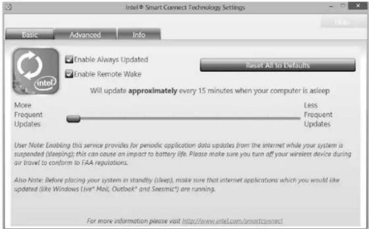
text_image
Intel • Smart Connect Technology Settings Basic Advanced Info Enable Always Updated Enable Remote Wake Reset All to Defaults Will update approximately every 15 minutes when your computer is asleep More Less Frequent Frequent Updates Updates User Note: Enabling this service provides for periodic application data updates from the internet while your system is suspended (sleeping); this can cause an impact to battery life. Please make sure you turn off your wireless device during air travel to conform to FAA regulations. Also Note: Before placing your system in standby (sleep), make sure that internet applications which you would like updated (like Windows Live* Mail, Outlook* and Seismic*) are running. For more information please visit http://www.intel.com/smartconnectUpdate Frequency slider: This slider bar sets the amount of time the feature waits to wake your computer and update your applications. Move the slider in the user interface to change the frequency. The slider bar can be set to wake and update your computer from every 15 to 60 minutes. The longer the time between updates the less power the feature consumes.
Reset All to Defaults button: This button is designed to reset Intel® Smart Connect Technology back to the original factory setting for wake frequency.
Advanced Tab
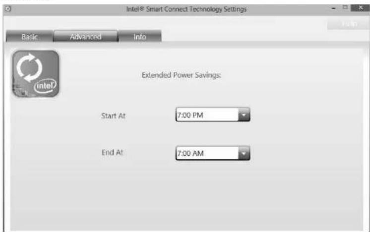
text_image
Intel® Smart Connect Technology Settings Basic Advanced.Info Extended Power Savings: Start At 7:00 PM End At 7:00 AMExtended Power Savings: You can set a time for Intel Smart Connect Technology to work in Extended Power Savings mode. This night time mode updates your computer every two hours, saving power for the times you are not using your computer.
Rapid Start Technology
Intel® Rapid Start technology enables your system to get up and running faster from even the deepest sleep, saving time and power consumption. Feel secure knowing that your system will still resume to working conditions in the event of unexpected power loss while in sleep mode.
System Requirement:
- An Intel® SATA SSD (SATA Gen2 or Gen3. Preferably Gen3, and 80 GB or larger)
● Windows 7 and Windows 8
Note1: Please visit below webpage for more details about operating systems supporting http://www.intel.com/p/en_US/support
Note2: The Rapid Start Technology is NOT supported by H81 chipset.
Installing Intel® SBA:
Step 1: BIOS Setting
1-1 Go to [Advanced Menu] > [ACPI Settings], and set [ACPI Sleep State] to S3 (Suspend to RAM)
1-2 Go to [Advanced Menu] > [SATA Configuration], and set [SATA Mode Selection] to AHCI
1-3 Go to [Advanced Menu] and set [Intel(R) Rapid Start Technology] to Enabled
1-4 Save your changes, and then exit the BIOS Setup.
Step 2: Operating System Installation
Step 3: Installing Intel® Rapid Start Application
3-1 Insert the setup Driver DVD into your optical drive. Click "Intel Rapid Start Technology" to launch the program.
3-2 Below window will pop-out, then click "Create Disk" to star disk partition. After disk partition finished, please click "OK" then system will reboot automatically.
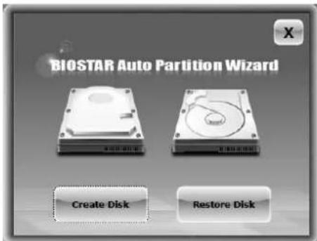
text_image
BIOSTAR Auto Partition Wizard Create Disk Restore Disk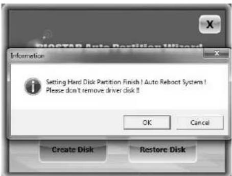
text_image
PROCTAR Auto Partition Wizard Information Setting Hard Disk Partition Finish ! Auto Reboot System ! Please don't remove driver disk ! OK Cancel Create Disk Restore Disk3-3 After rebooting, the system will setup Intel® Rapid Start Technology automatically. We recommend you restart the system after this installation is complete,
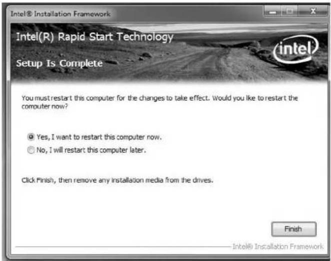
text_image
Intel® Installation Framework Intel(R) Rapid Start Technology Setup Is Complete You must restart this computer for the changes to take effect. Would you like to restart the computer now? ● Yes, I want to restart this computer now. ○ No, I will restart this computer later. Click Finish, then remove any installation media from the drives. Finish Intel® Installation FrameworkStep 4: Configuring Intel® Rapid Start Application
Launch the Intel® Rapid Start Technology Manager application from [Start] > [All Programs] > [Intel] or click the icon in the notification area.
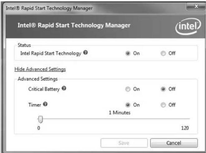
text_image
Intel® Rapid Start Technology Manager Intel® Rapid Start Technology Manager Status Intel Rapid Start Technology ? On Off Hide Advanced Settings Advanced Settings Critical Battery ? On Off Timer ? 1 Minutes 0 120 Save CancelLucid VIRTU MVP 2.0
Lucid VIRTU MVP 2.0 is designed for the platforms with one integrated and one discrete GPU. VIRTU MVP 2.0 dynamically assigns tasks to best available graphics resource based on power, performance and features.

text_image
Main Performance Applications Advanced About GPU Virtualization In-Game Icon Select the position for the In-Game icon: Show Show for a few seconds Hide Show in system traySystem Requirements:
● CPU: Any CPU with integrated graphics support
- Chipset: Any chipset with integrated graphics output
● Discrete GPU: Any Nvidia/ AMD GPU with DX9/ DX10/ DX11 support
● Memory Size: 2GB
● Operating System: Windows 7 and Windows 8
● Hard Disk Space: 20MB
BIOS Setting:
Please try to set Onboard VGA (IGD) as first display if you want to use "i-mode".
i-Mode:
i-Mode provides user with near zero performance overhead on 3D graphics games, Virtual VSync and Hyperformance features, integrated GPU special features and power saving options when no 3D gaming is used.
To use Lucid VIRTU Universal MVP solution in i-Mode, display must be always connected to motherboard video output.
Note: Display can be also connected to VGA or HDMI output instead of DVI output.
d-Mode:
d-Mode is provided for demanding 3D gamers to achieve uncompromised 3D performance of discrete GPU installed in the system, along with Virtual VSync and Hyperformance quality/performance improvement features. In this mode, Virtu Universal MVP allows user to utilize integrated GPU special features such as trascoding, while display is connected to discrete GPU.
Note1: In most cases the differences of 3D performance between i-Mode and d-Mode are unnoticeable to the user, so it is recommended to use i-mode to save power. Note2: To use Lucid VIRTU Universal MVP 2.0 solution in d-Mode, display must be connected to discrete GPU installed in the system.
Software Installation & Operation:
- GPU drivers must be installed prior to Lucid VIRTU MVP 2.0 installation.
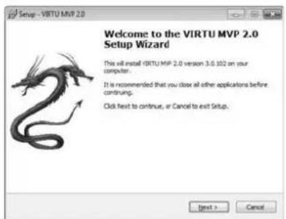
- The VIRTU MVP 2.0 Setup Wizard window is displayed.
-
Click Next and follow the on-screen instructions to complete the software installation.
-
When the installation is complete, "Completing the VIRTU MVP 2.0 Setup Wizard" window is displayed.
-
Select "Yes, restart the computer now" option and click Finish. The VIRTU MVP 2.0 installation process is completed.
-
Once installed, Virtu MVP logo shows on system tray (the right bottom corner of the screen). Mouse right click at the icon, will display the following screen.
-
When opening the VIRTU MVP 2.0 control panel (either from the start menu or from the system tray icon), the following window is displayed.
- By pressing button VIRTU MVP 2.0 solution is enabled.
text_image
Setup - VIRTU MVP 2.0 Welcome to the VIRTU MVP 2.0 Setup Wizard This will install VIRTU MVP 2.0 version 3.0.102 on your computer. It is recommended that you close all other applications before continuing. Click next to continue, or Cancel to exit Setup.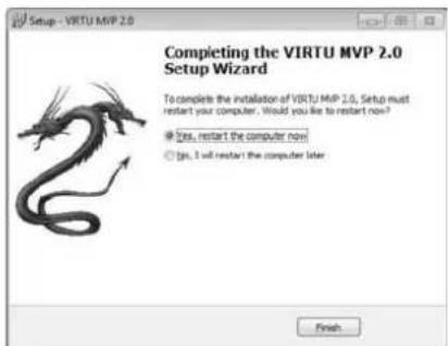
text_image
Setup - VIRTU MVP 2.0 Completing the VIRTU MVP 2.0 Setup Wizard To complete the installation of VIRTU MVP 2.0, Setup must restart your computer. Would you like to restart now? ● Yes, restart the computer now! ○ No, I will restart the computer later. Finish...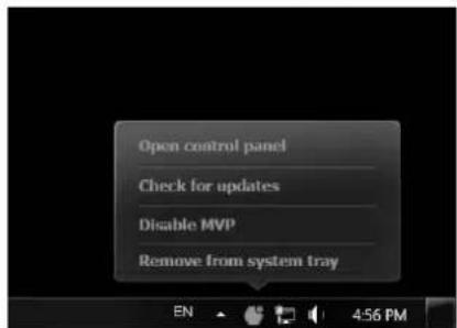
text_image
Open control panel Check for updates Disable MVP Remove from system tray
text_image
VRTU v9.2.0 HyperFormance Virtual VSync 1-modeNote: For more detail settings about Virtu MVP 2.0, please refer to the Virtu MVP 2.0 user's manual in the Setup DVD.
Green Power II Utility
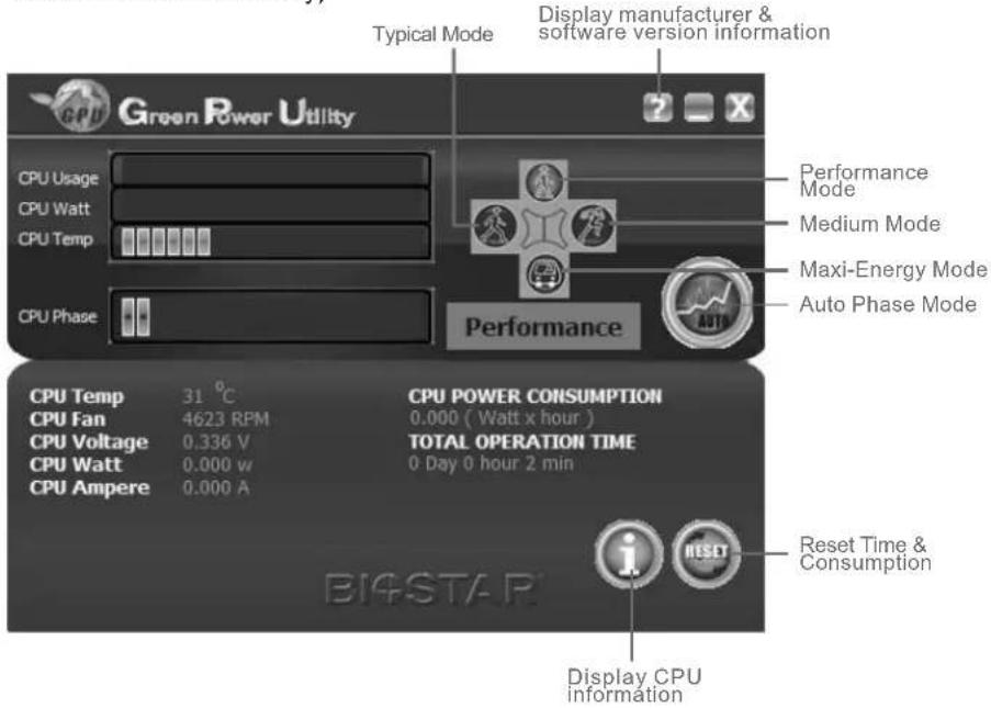
BIOSTAR G.P.U II (Green Power Utility) is a new function. The utility enhances energy efficiency by disabling extra phases while CPU is on light loading; it features 4+1 power phases, current power saving, and total power saving. This tool integrates a friendly GUI to monitor your CPU Usage, CPU Watt, and CPU Temperature. Moreover, it optimizes power saving and best power efficiency on your system. (The illustration below is for reference only)
text_image
Typical Mode Display manufacturer & software version information Green Power Utility CPU Usage CPU Watt CPU Temp CPU Phase Performance Mode Medium Mode Maxi-Energy Mode Auto Phase Mode CPU Temp 31 °C CPU Fan 4623 RPM CPU Voltage 0.336 V CPU Watt 0.000 w CPU Ampere 0.000 A CPU POWER CONSUMPTION 0.000 ( Watt x hour ) TOTAL OPERATION TIME 0 Day 0 hour 2 min Reset Time & Consumption Display CPU informationG.P.U Mode Setting:
This utility provides five modes, upon your requirements, to improve system performance or to save power consumption.
Note: Even if the modes saving more power consumption are chosen, the system still can keep excellent performance.
● Auto Phase Mode: System switches the mode automatically according to current system loading condition.
● Performance Mode: This is the mode saving power consumption most. Least energy will be used in the system.
● Typical Mode: Compared with that in Performance Mode, energy consumption in this mode is a little bit more.
● Medium Mode: The standard system power saving mode.
● Maxi-Energy Mode: The best system performance mode.
CHAPTER 4: USEFUL HELP
4.1 Driver Installation
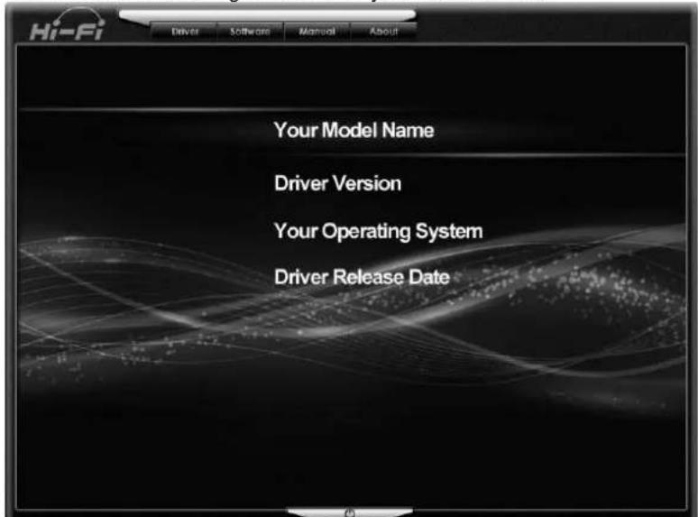
After you installed your operating system, please insert the Fully Setup Driver DVD into your optical drive and install the driver for better system performance.
You will see the following window after you insert the DVD
text_image
Hi-Fi Driver Software Manual About Your Model Name Driver Version Your Operating System Driver Release DateThe setup guide will auto detect your motherboard and operating system.
A. Driver Installation
To install the driver, please click on the Driver icon. The setup guide will list the compatible driver for your motherboard and operating system. Click on each device driver to launch the installation program.
B. Software Installation
To install the software, please click on the Software icon. The setup guide will list the software available for your system, click on each software title to launch the installation program.
C. Manual
Aside from the paperback manual, we also provide manual in the Driver DVD. Click on the Manual icon to browse for available manuals.
Note1: If this window didn't show up after you insert the Driver DVD, please use file browser to locate and execute the file SETUP.EXE under your optical drive. Note2: You will need Acrobat Reader to open the manual file. Please download the latest version of Acrobat Reader software from http://get.adobe.com/reader/
4.2 AMI BIOS Beep Code
Boot Block Beep Codes
| Number of Beeps | Description |
| Continuing Memory sizing error or Memory module not found | |
POST BIOS Beep Codes
| Number of Beeps | Description |
| 1 | Success booting. |
| 8 Display memory error (system video adapter) | |
4.3 AMI BIOS Post Code
| Code | Description |
| 10 PEI Core is started | |
| 11 Pre-memory CPU initialization is started | |
| 15 Pre-memory North Bridge initialization is started | |
| 19 Pre-memory South Bridge initialization is started | |
| 2B Memory initialization. Serial Presence Detect (SPD) data reading | |
| 2C Memory initialization. Memory presence detection | |
| 2D Memory initialization. Programming memory timing information | |
| 2E Memory initialization. Configuring memory | |
| 2F Memory initialization (other). | |
| 31 Memory Installed | |
| 32 CPU post-memory initialization is started | |
| 33 CPU post-memory initialization. Cache initialization | |
| 34 CPU post-memory initialization. Application Processor(s) (AP) initialization | |
| 35 CPU post-memory initialization. Boot Strap Processor (BSP) selection | |
| 36 CPU post-memory initialization. System Management Mode (SMM) initialization | |
| 37 Post-Memory North Bridge initialization is started | |
| 3B Post-Memory North Bridge initialization (North Bridge module specific) | |
| 4F DXE IPL is started | |
| 60 DXE Core is started | |
| F0 Recovery condition triggered by firmware (Auto recovery) | |
| F1 Recovery condition triggered by user (Forced recovery) | |
| F2 Recovery process started | |
| F3 Recovery firmware image is found | |
| F4 Recovery firmware image is loaded | |
| E0 S3 Resume is stared (S3 Resume PPI is called by the DXE IPL) | |
| E1 S3 Boot Script execution | |
| E2 Video repost | |
| E3 OS S3 wake vector call | |
| 60 DXE Core is started | |
| 61 NVRAM initialization | |
| 62 Installation of the South Bridge Runtime Services | |
| 63 CPU DXE initialization is started | |
| 68 PCI host bridge initialization | |
| 69 North Bridge DXE initialization is started | |
| 6A North Bridge DXE SMM initialization is started | |
| 70 South Bridge DXE initialization is started | |
| 71 South Bridge DXE SMM initialization is started | |
| 72 South Bridge devices initialization | |
| 78 South Bridge DXE Initialization (South Bridge module specific) | |
| 79 ACPI module initialization | |
| 90 Boot Device Selection (BDS) phase is started | |
| 91 Driver connecting is started | |
| 92 PCI Bus initialization is started | |
| 93 PCI Bus Hot Plug Controller Initialization | |
| 94 PCI Bus Enumeration | |
| 95 PCI Bus Request Resources | |
| 96 PCI Bus Assign Resources | |
| 97 Console Output devices connect | |
| 98 Console input devices connect | |
| 99 Super IO Initialization | |
| 9A USB initialization is started | |
| 9B USB Reset | |
| 9C USB Detect | |
| 9D USB Enable | |
| A0 IDE initialization is started | |
| A1 IDE Reset | |
| A2 IDE Detect | |
| A3 IDE Enable | |
| A4 SCSI initialization is started | |
| A5 SCSI Reset | |
| A6 SCSI Detect | |
| A7 SCSI Enable | |
| A8 Setup Verifying Password | |
| A9 Start of Setup | |
| AB Setup Input Wait | |
| AD Ready To Boot event | |
| AE Legacy Boot event | |
| AF Exit Boot Services event | |
| B0 Runtime Set Virtual Address MAP Begin | |
| B1 Runtime Set Virtual Address MAP End | |
| B2 Legacy Option ROM Initialization | |
| B3 System Reset | |
| B4 USB hot plug | |
| B5 PCI bus hot plug | |
| B6 Clean-up of NVRAM | |
| B7 Configuration Reset (reset of NVRAM settings) | |
4.4 Troubleshooting
| Probable | Solution |
| 1. There is no power in the system. Power LED does not shine; the fan of the power supply does not work2. Indicator light on keyboard does not shine. | 1. Make sure power cable is securely plugged in.2. Replace cable.3. Contact technical support. |
| System is inoperative. Keyboard lights are on, power indicator lights are lit, and hard drives are running. | Using even pressure on both ends of the DIMM, press down firmly until the module snaps into place. |
| System does not boot from a hard disk drive, but can be booted from optical drive. | 1. Check cable running from disk to disk controller board. Make sure both ends are securely plugged in; check the drive type in the standard CMOS setup.2. Backing up the hard drive is extremely important. All hard disks are capable of breaking down at any time. |
| System only boots from an optical drive. Hard disks can be read, applications can be used, but system fails to boot from a hard disk. | 1. Back up data and applications files.2. Reformat the hard drive. Re-install applications and data using backup disks. |
| Screen message shows “Invalid Configuration” or “CMOS Failure.” | Review system’s equipment. Make sure correct information is in setup. |
| System cannot boot after user installs a second hard drive. | 1. Set master/slave jumpers correctly.2. Run SETUP program and select correct drive types. Call the drive manufacturers for compatibility with other drives. |
CPU Overheated
If the system shutdown automatically after power on system for seconds, that means the CPU protection function has been activated.
When the CPU is over heated, the motherboard will shutdown automatically to avoid a damage of the CPU, and the system may not power on again.
In this case, please double check:
- The CPU cooler surface is placed evenly with the CPU surface.
- CPU fan is rotated normally.
- CPU fan speed is fulfilling with the CPU speed.
After confirmed, please follow steps below to relief the CPU protection function.
- Remove the power cord from power supply for seconds.
- Wait for seconds.
- Plug in the power cord and boot up the system.
Or you can:
- Clear the CMOS data.
- Wait for seconds.
- Power on the system again.
4.5 RAID Functions
RAID Definitions
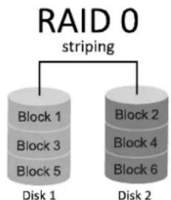
RAID 0:
flowchart
graph TD
    A["RAID 0 striping"] --> B["Block 1"]
    A --> C["Block 2"]
    A --> D["Block 3"]
    A --> E["Block 4"]
    A --> F["Block 5"]
    A --> G["Disk 1"]
    A --> H["Disk 2"]
In a RAID 0 system data are split up in blocks that get written across all the drives in the array. By using multiple disks (at least 2) at the same time, this offers superior I/O performance. This performance can be enhanced further by using multiple controllers, ideally one controller per disk.
Features and Benefits
- Drives: Minimum 2, and maximum is up to 6 or 8. Depending on the platform.
- Uses: Intended for non-critical data requiring high data throughput, or any environment that does not require fault tolerance.
- Benefits: provides increased data throughput, especially for large files. No capacity loss penalty for parity.
- Drawbacks: Does not deliver any fault tolerance. If any drive in the array fails, all data is lost.
- Fault Tolerance: No.
- Total Capacity: (Minimal. HDD Capacity) x (Connected HDDs Amount)
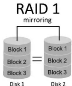
RAID 1:
flowchart
graph TD
    A["Block 1"] --> B["Block 2"]
    B --> C["Block 3"]
    D["Block 1"] --> E["Block 2"]
    E --> F["Block 3"]
    G["Disk 1"] --> H["Disk 2"]
    I["RAID 1 mirroring"] --> J["Block 1"]
    I --> K["Block 2"]
    I --> L["Block 3"]
Data are stored twice by writing them to both the data disk (or set of data disks) and a mirror disk (or set of disks). If a disk fails, the controller uses either the data drive or the mirror drive for data recovery and continues operation. You need at least 2 disks for a RAID 1 array.
Features and Benefits
- Drives: Minimum 2, and maximum is 2.
- Uses: RAID 1 is ideal for small databases or any other application that requires fault tolerance and minimal capacity.
- Benefits: Provides 100% data redundancy. Should one drive fail, the controller switches to the other drive.
- Drawbacks: Requires 2 drives for the storage space of one drive. Performance is impaired during drive rebuilds.
- Fault Tolerance: Yes.
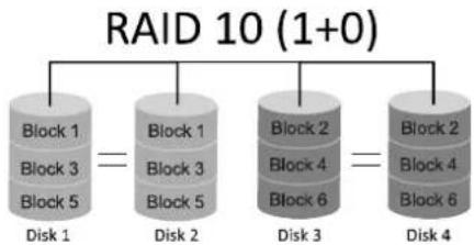
RAID 10:
flowchart
graph TD
    A["RAID 10 (1+0)"] --> B["Block 1"]
    A --> C["Block 2"]
    A --> D["Block 3"]
    A --> E["Block 4"]
    A --> F["Block 5"]
    B --> G["Disk 1"]
    C --> H["Disk 2"]
    D --> I["Disk 3"]
    E --> J["Disk 4"]
    F --> K["Disk 5"]
RAID 10 combines the advantages (and disadvantages) of RAID 0 and RAID 1 in one single system. It provides security by mirroring all data on a secondary set of disks (disk 3 and 4 in the drawing below) while using striping across each set of disks to speed up data transfers.
Features and Benefits
- Drives: Minimum 4, and maximum is 6 or 8, depending on the platform.
- Benefits: Optimizes for both fault tolerance and performance, allowing for automatic redundancy. May be simultaneously used with other RAID levels in an array, and allows for spare disks.
- Drawbacks: Requires twice the available disk space for data redundancy, the same as RAID level 1.
- Fault Tolerance: Yes.
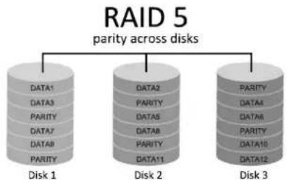
RAID 5:
flowchart
graph TD
    A["RAID 5"] --> B["parity across disks"]
    B --> C["Disk 1"]
    B --> D["Disk 2"]
    B --> E["Disk 3"]
    C --> F["DATA1"]
    C --> G["DATA2"]
    C --> H["PARITY"]
    D --> I["DATA3"]
    D --> J["PARITY"]
    D --> K["DATA4"]
    D --> L["PARITY"]
    D --> M["DATA5"]
    D --> N["DATA6"]
    D --> O["PARITY"]
    D --> P["PARITY"]
    D --> Q["DATA7"]
    D --> R["PARITY"]
    D --> S["DATA8"]
    D --> T["PARITY"]
    D --> U["DATA9"]
    D --> V["PARITY"]
    E --> W["DATA10"]
    E --> X["PARITY"]
    E --> Y["DATA11"]
    E --> Z["PARITY"]
    E --> AA["DATA12"]
A RAID 5 array can withstand a single disk failure without losing data or access to data. Although RAID 5 can be achieved in software, a hardware controller is recommended. Often extra cache memory is used on these controllers to improve the write performance.
Features and Benefits
- Drives: Minimum 3.
- Uses: RAID 5 is recommended for transaction processing and general purpose service.
- Benefits: An ideal combination of good performance, good fault tolerance, and high capacity and storage efficiency.
- Drawbacks: Individual block data transfer rate same as a single disk. Write performance can be CPU intensive.
- Fault Tolerance: Yes.
Note1: The RAID 0,1,10 and 5 functions are only supported by Z87 & H87 chipsets.
Note2: For more details settings about Intel® Rapid Storage Technology (Intel® RST), please visit http://www.intel.com/p/en_US/support/highlights/chpsts/imsm
This Page Intentionally Left Blank
APPENDIX: Specifications in Other Languages
Arabic