BI-785G-M35 - Motherboard DFI - Free user manual and instructions
Find the device manual for free BI-785G-M35 DFI in PDF.

| Product Type | Motherboard |
| Brand | DFI |
| Model | BI-785G-M35 |
| Form Factor | Micro-ATX |
| Dimensions (W x H) | 244 x 244 mm |
| Weight | 0.5 kg (approx) |
| Chipset | AMD 785G + SB710 |
| CPU Socket | AM3+ (compatible with AM3) |
| Supported Memory | DDR3, up to 16 GB, dual channel |
| Expansion Slots | 1x PCIe x16, 1x PCIe x1, 2x PCI |
| Storage Interfaces | 6x SATA 3.0 Gb/s, 1x IDE |
| USB Ports | 8x USB 2.0, 2x USB 3.0 (rear) |
| Video Output | VGA, DVI, HDMI |
| Audio | Realtek ALC662 6-channel HD Audio |
| LAN | Realtek RTL8111DL Gigabit Ethernet |
| Power Connector | 24-pin ATX, 4-pin CPU |
| Operating Temperature | 0°C to 60°C |
| Cleaning Instructions | Use compressed air; avoid liquids |
| Safety Certifications | CE, FCC |
| Spare Parts Availability | Contact DFI support for replacement |
Frequently Asked Questions - BI-785G-M35 DFI
User questions about BI-785G-M35 DFI
0 question about this device. Answer the ones you know or ask your own.
Ask a new question about this device
Download the instructions for your Motherboard in PDF format for free! Find your manual BI-785G-M35 - DFI and take your electronic device back in hand. On this page are published all the documents necessary for the use of your device. BI-785G-M35 by DFI.
USER MANUAL BI-785G-M35 DFI
This publication contains information that is protected by copyright. No part of it may be reproduced in any form or by any means or used to make any transformation/adaptation without the prior written permission from the copyright holders.
This publication is provided for informational purposes only. The manufacturer makes no representations or warranties with respect to the contents or use of this manual and specifically disclaims any express or implied warranties of merchantability or fitness for any particular purpose. The user will assume the entire risk of the use or the results of the use of this document. Further, the manufacturer reserves the right to revise this publication and make changes to its contents at any time, without obligation to notify any person or entity of such revisions or changes.
© 2009. All Rights Reserved.
Trademarks
Windows® 2000 and Windows® XP are registered trademarks of Microsoft Corporation. Award is a registered trademark of Award Software, Inc. Other trademarks and registered trademarks of products appearing in this manual are the properties of their respective holders.
FCC and DOC Statement on Class B
This equipment has been tested and found to comply with the limits for a Class B digital device, pursuant to Part 15 of the FCC rules. These limits are designed to provide reasonable protection against harmful interference when the equipment is operated in a residential installation. This equipment generates, uses and can radiate radio frequency energy and, if not installed and used in accordance with the instruction manual, may cause harmful interference to radio communications. However, there is no guarantee that interference will not occur in a particular installation. If this equipment does cause harmful interference to radio or television reception, which can be determined by turning the equipment off and on, the user is encouraged to try to correct the interference by one or more of the following measures:
• Reorient or relocate the receiving antenna.
- Increase the separation between the equipment and the receiver.
- Connect the equipment into an outlet on a circuit different from that to which the receiver is connected.
- Consult the dealer or an experienced radio TV technician for help.
Notice:
- The changes or modifications not expressly approved by the party responsible for compliance could void the user's authority to operate the equipment.
- Shielded interface cables must be used in order to comply with the emission limits.
Table of Contents
Copyright....2
Trademarks 2
FCC and DOC Statement on Class B 3
Warranty 7
Static Electricity Precautions 8
Safety Measures 8
About the Package 9
Before Using the System Board 9
Chapter I - Introduction ...... 10
Specifications....10
Features 12
Chapter 2 - Hardware Installation ...... 15
System Board Layout 15
System Memory 16
Installing the DIM Module 19
CPU 21
Installing the CPU 21
Installing the Fan and Heat Sink 24
Northbridge Heat Sink 26
Jumper Settings....27
Clear CMOS Data 27
PS/2 Power Select 28
USB Power Select 29
PCIE Gen 1 / Gen 2 Select 29
HDMI/DVI Select 30
Rear Panel I/O Ports 30
PS/2 Ports and S/PDIF Ports 31
HDMI, VGA and DVI-I Ports 32
USB and LAN Ports 33
Audio 34
Internal I/O Connectors 35
Serial ATA Connectors 35
FDD Connector and IDE Connector 36
Serial (COM) Connectors 37
Cooling Fan Connectors 38
LEDs 39
Power Connectors 40
Front Panel Connectors 42
PCI Express Slots 44
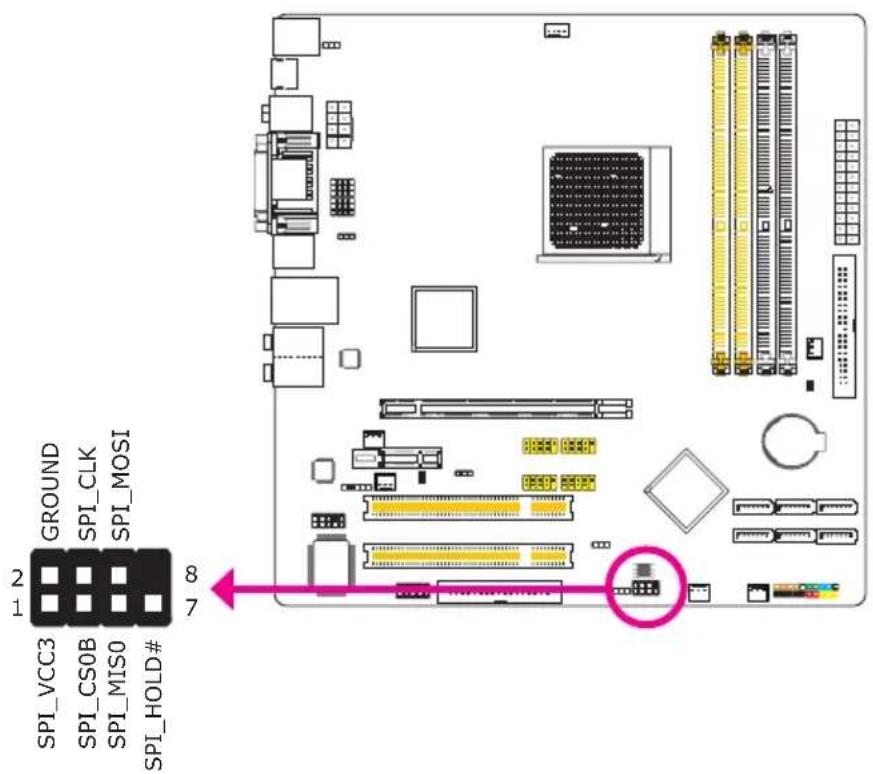
Download Flash BIOS Connector 44
Chapter 3 - BIOS Setup 45
Switchable Modes for Overclocking 45
Easy Mode 45
Advance Mode 45
Award BIOS Setup Utility 46
Standard CMOS Features 47
Advanced BIOS Features 51
Advanced Chipset Features 54
Integrated Peripherals 60
Power Management Setup 67
PnP/PCI Configurations 71
PC Health Status 74
Genie BIOS Setting 76
CMOS Reloaded 88
Load Optimized Defaults 91
Set Supervisor Password 92
Set User Password 93
Save & Exit Setup 94
Exit Without Saving 95
RAID BIOS 96
Updating the BIOS....97
Chapter 4 - Supported Software 98
AMD RS880 Drivers 99
AMD South Bridge Drivers....103
WebPAM Utility.... 107
ATi Radeon Drivers....110
nVidia GForce 8 Series Drivers....114
Realtek Audio Drivers.... 116
JMC250 LAN Drivers 118
RAID Floppy Driver.... 120
Smart Guardian 121
AMD OverDrive.... 124
Adobe Acrobat Reader 7.05 128
Chapter 5 - RAID 130
RAID Levels 130
RAID 0 (Striped Disk Array without Fault Tolerance) ...... 130
RAID 1 (Mirroring Disk Array with Fault Tolerance) ...... 130
RAID 0+1 (Striping and Mirroring) 130
Settings 130
Step 1: Connect the Serial ATA Drives ...... 131
Step 2: Configure Serial ATA in the Award BIOS .... 131
Step 3: Configure RAID in the RAID BIOS .... 131
Step 4: Install the RAID Driver During OS Installation ..... 131
Chapter 6 - Hybrid Graphics.... 133
Basic Requirements 133
Hybrid Graphics Setup 133
Chapter 7 - Cool'n'Quiet Technology 134
Cool'n'Quiet Technology 134
Chapter 8 - Dual Display Configuration.... 136
Display Interfaces 136
Dual Display Configuration 138
Chapter 9 - Audio Configuration.... 139
Configuring 2/4/5.1/7.1-Channel Audio 139
High Definition Audio (HD Audio) 140
Appendix A - ABS: Auto Boost System 144
Installing ABS 144
The ABS Utility 147
Appendix B - Troubleshooting.... 152
Appendix C - Debug LED Post and Troubleshooting 156
Warranty
-
Warranty does not cover damages or failures that arised from misuse of the product, inability to use the product, unauthorized replacement or alteration of components and product specifications.
-
The warranty is void if the product has been subjected to physical abuse, improper installation, modification, accidents or unauthorized repair of the product.
-
Unless otherwise instructed in this user's manual, the user may not, under any circumstances, attempt to perform service, adjustments or repairs on the product, whether in or out of warranty. It must be returned to the purchase point, factory or authorized service agency for all such work.
-
We will not be liable for any indirect, special, incidental or consequential damages to the product that has been modified or altered.
Static Electricity Precautions
It is quite easy to inadvertently damage your PC, system board, components or devices even before installing them in your system unit. Static electrical discharge can damage computer components without causing any signs of physical damage. You must take extra care in handling them to ensure against electrostatic build-up.
- To prevent electrostatic build-up, leave the system board in its anti-static bag until you are ready to install it.
- Wear an antistatic wrist strap.
- Do all preparation work on a static-free surface.
- Hold the device only by its edges. Be careful not to touch any of the components, contacts or connections.
- Avoid touching the pins or contacts on all modules and connectors. Hold modules or connectors by their ends.

Important:
Electrostatic discharge (ESD) can damage your processor, disk drive and other components. Perform the upgrade instruction procedures described at an ESD workstation only. If such a station is not available, you can provide some ESD protection by wearing an antistatic wrist strap and attaching it to a metal part of the system chassis. If a wrist strap is unavailable, establish and maintain contact with the system chassis throughout any procedures requiring ESD protection.
Safety Measures
To avoid damage to the system:
• Use the correct AC input voltage range.
To reduce the risk of electric shock:
- Unplug the power cord before removing the system chassis cover for installation or servicing. After installation or servicing, cover the system chassis before plugging the power cord.
Battery:
• Danger of explosion if battery incorrectly replaced.
- Replace only with the same or equivalent type recommend by the manufacturer.
- Dispose of used batteries according to local ordinance.
About the Package
The system board package contains the following items. If any of these items are missing or damaged, please contact your dealer or sales representative for assistance.
☑ One system board
One IDE cable
☑ Two Serial ATA data cables
☑ One Serial ATA power cable
☑ One I/O shield
One DVD
☑ One multilingual installation guide
The system board and accessories in the package may not come similar to the information listed above. This may differ in accordance to the sales region or models in which it was sold. For more information about the standard package in your region, please contact your dealer or sales representative.
Before Using the System Board
Before using the system board, prepare basic system components.
If you are installing the system board in a new system, you will need at least the following internal components.
A CPU
- Memory module
• Storage devices such as hard disk drive, CD-ROM, etc.
You will also need external system peripherals you intend to use which will normally include at least a keyboard, a mouse and a video display monitor.
Specifications
| Processor | • AMD® PhenomTM II processor• HyperTransport 3.0 (5200MT/s)• AMD OverDrive provides tuning options using the new “Advanced Clock Calibration” overclocking feature.• Socket 938 AM3+ 45nm |
| Chipset | • AMD chipset- Northbridge: AMD 785G- Southbridge: AMD SB710 |
| System Memory | • Four 240-pin DDR3 DIMM sockets• Supports DDR3 1600(O.C.)/1333/1066/800 MHz• Dual channel (128-bit wide) memory interface• Supports non-ECC unbuffered DIMMs• Supports up to 16GB system memory• 128MB DDR3 Sideport memory |
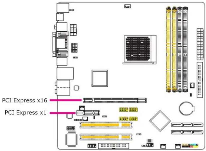
| Expansion Slots | • 1 PCI Express (Gen 2) x16 slot• 1 PCI Express x1 slot• 2 PCI slots |
| BIOS | • Award BIOS• CMOS Reloaded• 8Mbit SPI Flash ROM |
| Graphics | • Integrated ATI RadeonTM HD 4200 graphics core• Onboard graphics interface- HDMI port for both digital audio and video HD display- DVI-I port for digital LCD display (DVI-D signal only)• Microsoft® DirectX 10.1• CrossFireXTM (Hybrid Graphics) technology combines the onboard GPU and a discrete PCIE graphics card• Onboard Performance cache for added performance |
| Audio | • Realtek ALC885 High Definition audio CODEC• 8-channel audio output• DAC SNR/ADC SNR of 106dB/101dB• Full-rate lossless content protection technology• Optical S/PDIF-out and coaxial RCA S/PDIF-out interfaces |
| LAN | • JMicron JMC250 PCIE Gigabit LAN controllers• Fully compliant to IEEE 802.3 (10BASE-T), 802.3u (100BASE-TX) and 802.3ab (1000BASE-T) standards |
| IDE | • One IDE connector allows connecting up to two UltraDMA 133Mbps hard drives |
| Serial ATA with RAID | • Supports up to 6 SATA devices• SATA speed up to 3Gb/s• RAID 0, RAID 1 and RAID 0+1 |
| Rear Panel I/O | 1 mini-DIN-6 PS/2 mouse port1 mini-DIN-6 PS/2 keyboard port1 HDMI-out port1 coaxial RCA S/PDIF-out port1 optical S/PDIF-out port1 VGA port1 DVI-I port (DVI-D signal only)4 USB 2.0/1.1 ports1 RJ45 LAN portCenter/subwoofer, rear R/L and side R/L jacksLine-in, line-out (front R/L) and mic-in jacks |
| Internal I/O | 4 connectors for 8 additional external USB 2.0 ports1 connector for an external COM port1 front audio connector1 S/PDIF connector6 Serial ATA connectors1 40-pin IDE connector1 floppy connector1 24-pin ATX power connector1 8-pin 12V power connector1 front panel connector1 download flash BIOS connector6 fan connectors |
| Power Management | ACPI and OS Directed Power ManagementACPI STR (Suspend to RAM) functionWake-On-PS/2 Keyboard/MouseWake-On-USB Keyboard/MouseWake-On-RingWake-On-LANRTC timer to power-on the systemAC power failure recovery |
| Hardware Monitor | Monitors CPU/system/chipset temperatureMonitors 12V/5V/3.3V/Vcore/Vbat/5Vsb/Vdimm/Vchip voltagesMonitors the speed of the cooling fansCPU Overheat Protection function monitors CPU temperature during system boot-up |
| PCB | microATX form factor24.5cm (9.64") x 24.5cm (9.64") |
Features
DDR3
DDR3 delivers increased system bandwidth and improved performance. It offers peak data transfer rate of up to 21 Gb/s bandwidth. The advantages of DDR3 are its higher bandwidth and its increase in performance at a lower power than DDR2.
CrossFireX (Hybrid Graphics)
Based on the ATI CrossFire ^™ multi-GPU technology, CrossFireX ^™ (Hybrid Graphics) takes gaming experience to the next level. Hybrid Graphics is a combination of the integrated graphics and a discrete graphics card delivering high quality gaming images and improved performance. Its multi-GPU performance capabilities enhance gaming performance, productivity and platform power efficiency to the mainstream PC.
PCI Express Gen 2
PCI Express Gen 2 is a high bandwidth I/O infrastructure that possesses the ability to scale speeds by forming multiple lanes. The x16 PCI Express lane supports transfer rate up to 5Gb/s.
Integrated Graphics
The northbridge chip comes integrated with the ATI RadēönHD 4200 graphics core delivering exceptional 3D graphics performance. It supports HDMI and DVI interfaces.
DVI
DVI (Digital Visual Interface) is a form of video interface technology made to maximize the quality of flat panel LCD monitors and modern video graphics cards. Data is transmitted using the TMDS (Transition Minimized Differential Signaling) protocol, providing a digital signal from the PC's graphics subsystem to the display.
HDMI
HDMI (High-Definition Multimedia Interface) is a compact audio/video connector interface for transmitting uncompressed digital streams. It delivers multi-channel audio and uncompressed digital video signals for full HD 1080p visuals through a single cable. Connect a LCD monitor or digital TV that has the HDMI port.
8CH High Definition Audio
The onboard Realtek ALC885 is a High Definition audio codec and the 6 audio jacks at the rear I/O panel provides 8-channel audio output for advanced 7.1-channel super surround sound audio system. ALC885 also supports S/PDIF output, allowing digital connections with DVD systems or other audio/video multimedia.
S/PDIF
S/PDIF is a standard audio file transfer format that transfers digital audio signals to a device without having to be converted first to an analog format. This prevents the quality of the audio signal from degrading whenever it is converted to analog. S/PDIF is usually found on digital audio equipment such as a DAT machine or audio processing device. The S/PDIF interface on the system board sends surround sound and 3D audio signal outputs to amplifiers and speakers and to digital recording devices like CD recorders.
Serial ATA with RAID
Serial ATA is a storage interface that is compliant with SATA 1.0 specification. It supports speed of up to 3Gb/s. Serial ATA improves hard drive performance faster than the standard parallel ATA whose data transfer rate is 100MB/s. The system board allows configuring RAID on Serial ATA devices. It supports RAID 0/1/0+1.
Gigabit LAN
The JMicron JMC250 PCI Express Gigabit LAN chip supports up to 1Gbps dat rate.
CMOS Reloaded
CMOS Reloaded is a technology that allows storing multiple user-defined BIOS settings by using the BIOS utility to save, load and name the settings. This is especially useful to overclockers who require saving a variety of overclocked settings and being able to conveniently switch between these settings simultaneously.
Genie BIOS
The options in Genie BIOS allows configuring the system to optimize system performance and overclock capability.
1
Introduction
CPU Overheat Protection
CPU Overheat Protection has the capability of monitoring the CPU's temperature during system boot up. Once the CPU's temperature exceeded the temperature limit pre-defined by the CPU, the system will automatically shutdown. This preventive measure has been added to protect the CPU from damage and insure a safe computing environment.
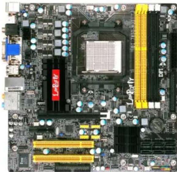
System Board Layout

Important:
Electrostatic discharge (ESD) can damage your system board, processor, disk drives, add-in boards, and other components. Perform the upgrade instruction procedures described at an ESD workstation only. If such a station is not available, you can provide some ESD protection by wearing an antistatic wrist strap and attaching it to a metal part of the system chassis. If a wrist strap is unavailable, establish and maintain contact with the system chassis throughout any procedures requiring ESD protection.
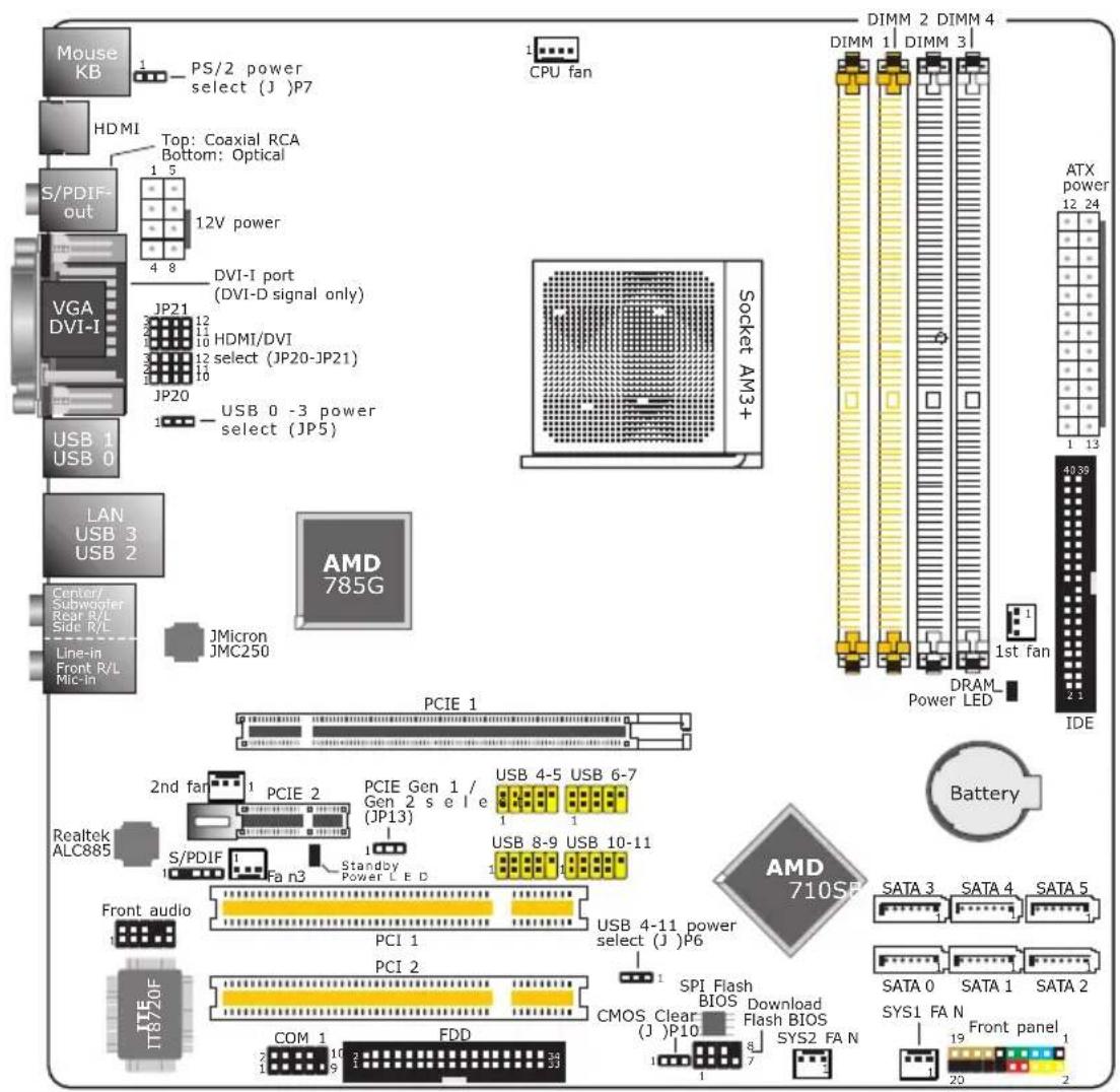
System Memory

Important:
When the DRAM Power LED lit red, it indicates that power is present on the DIMM sockets. Power-off the PC then unplug the power cord prior to installing any memory modules. Failure to do so will cause severe damage to the motherboard and components.
The four DIMM sockets are divided into 2 channels:
Channel A - DIMM 1 and DIMM 2
Channel B - DIMM 3 and DIMM 4
The system board supports the following memory interface.
Single Channel (SC)
Data will be accessed in chunks of 64 bits (8B) from the memory channels.
Virtual Single Channel (VSC)
If both channels are populated with different memory configurations, the MCH defaults to Virtual Single Channel.
Dual Channel (DC)
Dual channel provides better system performance because it doubles the data transfer rate.
Dynamic Mode Addressing
This mode minimizes the overhead of opening/closing pages in memory banks allowing for row switching to be done less often.
| Single Channel | DIMMs are on the same channel.DIMMs in a channel can be identical or completely different.Not all slots need to be populated. |
| Virtual Single Channel | DIMMs of different memory configurations are on different channels.Odd number of slots can be populated. |
| Dual Channel | DIMMs of the same memory configuration are on different channels. |
| Dynamic Mode Addressing | In single channel, requires even number or rows (side of the DIMM) populated. This mode can be enabled with 1 SS, 2 SS or 2 DS.In VSC mode, both channels must have identical row structure. |
BIOS Setting
Configure the system memory in the Genie BIOS Setting submenu of the BIOS. Refer to chapter 3 for more information.
The table below lists the various optimal operating modes that should be configured for the memory channel operation.
| Config | DIMM 1 | DIMM 2 | DIMM 3 | DIMM 4 |
| No memory | E | E | E | E |
| Single channel A | P | E | E | E |
| Single channel A | P | P | E | E |
| Single channel A | E | P | E | E |
| Single channel B | E | E | P | E |
| Single channel B | E | E | P | P |
| Single channel B | E | E | E | P |
| Virtual single channel | E | P(**) | E | P(**) |
| Virtual single channel | E | P | P | E |
| Virtual single channel | E | P(**) | P | P(**) |
| Virtual single channel | P | E | E | P |
| Virtual single channel | P(**) | E | P(**) | E |
| Virtual single channel | p(**) | E | P(**) | P |
| Virtual single channel | P | P(**) | E | P(**) |
| Virtual single channel | P(**) | P | P(**) | E |
| Virtual single channel | P(**) | P(**) | P(**) | P(**) |
| Dual channel | E | P(*(2,4) | E | P(*(2,4) |
| Dual channel | P(*(1,3) | E | P(*(1,3) | E |
| Dual channel | P(*(1,3) | P(*(2,4) | P(*(1,3) | P(*(2,4) |
| Dynamic Mode Addressing | E | P(*(2,4) DS | E | P(*(2,4) DS |
| Dynamic Mode Addressing | P(*(1,3) DS | E | P(*(1,3) DS | E |
| Dynamic Mode Addressing | P(*(1,3) DS | P(*(2,4) DS | P(*(1,3) DS | P(*(2,4) DS |
| Dynamic Mode Addressing | E | P(*(2,4) SS | E | P(*(2,4) SS |
| Dynamic Mode Addressing | P(*(1,3) SS | E | P(*(1,3) SS | E |
| Dynamic Mode Addressing | P(*(1,3) SS | P(*(2,4) SS | P(*(1,3) SS | P(*(2,4) SS |
P - denotes populated
E - denotes empty
* - denotes DIMMs are identical
** - denotes DIMMs are not identical
SS - denotes Single Sided DIMM
DS - denotes Double Sided DIMM
1, 2, 3 or 4 - denotes the DDR DIMM slot
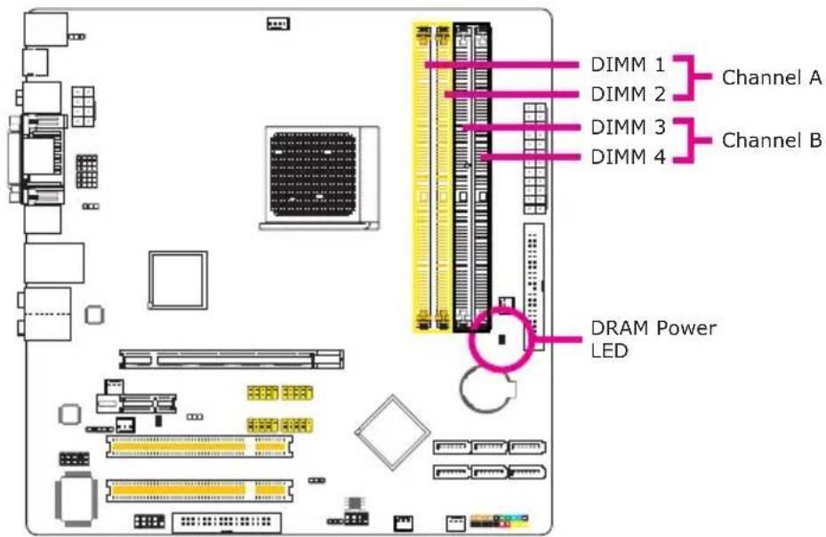
Installing the DIM Module

Note:
The system board used in the following illustrations may not resemble the actual board. These illustrations are for reference only.
- Make sure the PC and all other peripheral devices connected to it has been powered down.
- Disconnect all power cords and cables.
- Locate the DIMM socket on the system board.
- Push the "ejector tabs" which are at the ends of the socket to the side.
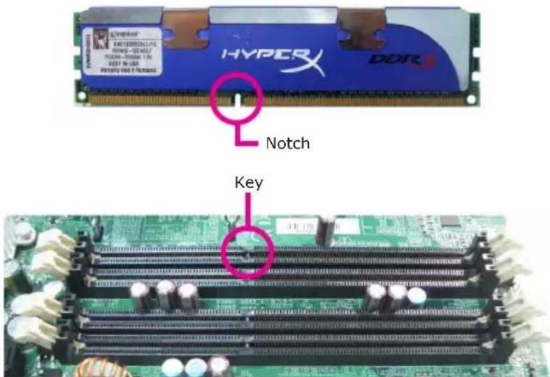
- Note how the module is keyed to the socket.
2
Hardware Installation
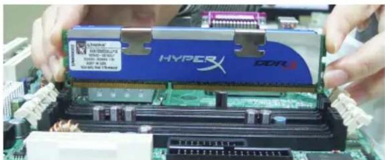
- Grasping the module by its edges, position the module above the socket with the "notch" in the module aligned with the "key" on the socket. The keying mechanism ensures the module can be plugged into the socket in only one way.
natural_image
Close-up of hands installing a HYPERX DDR into a motherboard (no visible text or symbols on the chip itself)- Seat the module vertically, pressing it down firmly until it is completely seated in the socket.
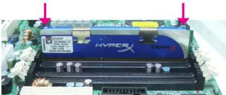
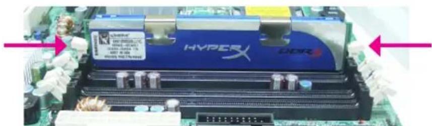
- The ejector tabs at the ends of the socket will automatically snap into the locked position to hold the module in place.
CPU
The system board is equipped with Socket AM3+ for installing an AMD CPU designed for this socket.
Installing the CPU
-
Make sure the PC and all other peripheral devices connected to it has been powered down.
-
Disconnect all power cords and cables.
-
Locate Socket AM3+ on the system board.
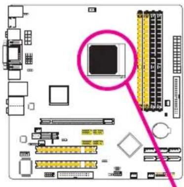
natural_image
Computer motherboard diagram showing CPU socket and memory card (no text or labels)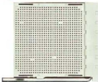
- Unlock the socket by pushing the lever sideways, away from the socket, then lifting it up to a 90 angle. Make sure the lever is lifted to at least this angle otherwise the CPU will not fit in properly.

2
Hardware Installation
- Position the CPU above the socket. The gold mark on the CPU must align with pin 1 of the CPU socket.
Important:
Handle the CPU by its edges and avoid touching the pins.
Gold mark
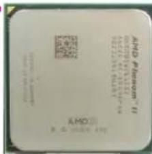
Pin 1
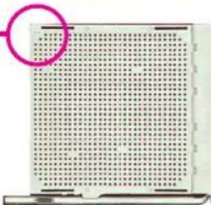
natural_image
Grid of small black dots on white background, no text or symbols visible- Insert the CPU into the socket until it is seated in place. The CPU will fit in only one orientation and can easily be inserted without exerting any force.
Important:
Do not force the CPU into the socket. Forcing the CPU into the socket may bend the pins and damage the CPU.
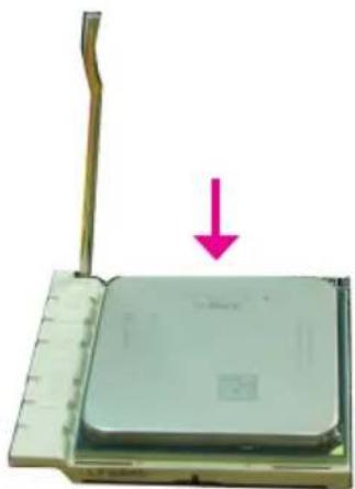
natural_image
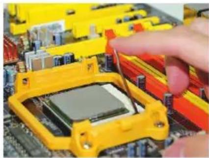
Close-up of a computer processor with a pink downward arrow indicating compression or disassembly (no text or symbols visible)- Once the CPU is in place, push down the lever to lock the socket. The lever should click on the side tab to indicate that the CPU is completely secured in the socket.
natural_image
Close-up of a hand inserting a microchip into a yellow plastic housing on a computer motherboard (no visible text or symbols)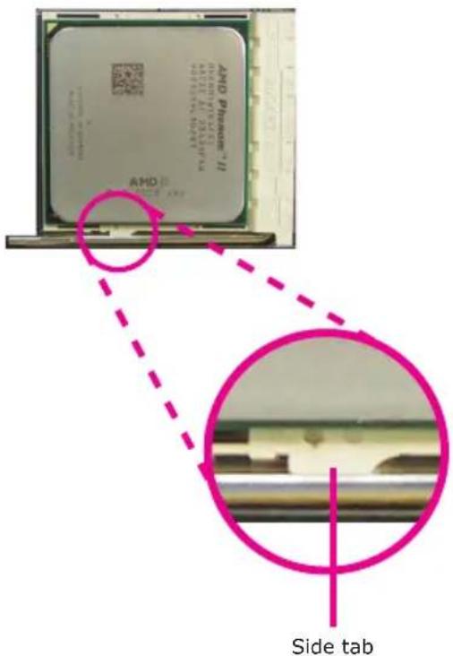
Installing the Fan and Heat Sink
The CPU must be kept cool by using a CPU fan with heat sink. Without sufficient air circulation across the CPU and heat sink, the CPU will overheat damaging both the CPU and system board.
The fan / heat sink assembly must provide airflow adequate to ensure appropriate internal temperature and cooling of the components in the system. Failure to use the appropriate cooling system may result in reduced performance or, in some instances, damage to the system board.

Note:
• Use only certified fan and heat sink.
- The fan and heat sink package usually contains the fan and heat sink assembly, and an installation guide. If the installation procedure in the installation guide differs from the one in this section, please follow the installation guide in the package.
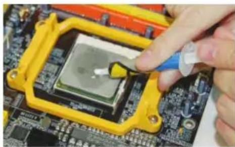
- Before you install the fan / heat sink, you must apply a thermal paste onto the top of the CPU. Do not apply the paste if the fan / heat sink already has a patch of thermal paste on its underside. Peel the strip that covers the paste before you place the fan / heat sink on top of the CPU.
The thermal paste is usually supplied when you purchase the CPU or fan heat sink assembly. Do not spread the paste all over the surface. When you later place the heat sink on top of the CPU, the compound will disperse evenly.
natural_image
Close-up of a hand using a tool to clean or inspect a microchip on a circuit board (no visible text or symbols)- The system board comes with the retention module base already installed.
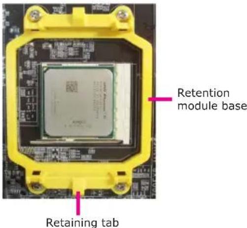
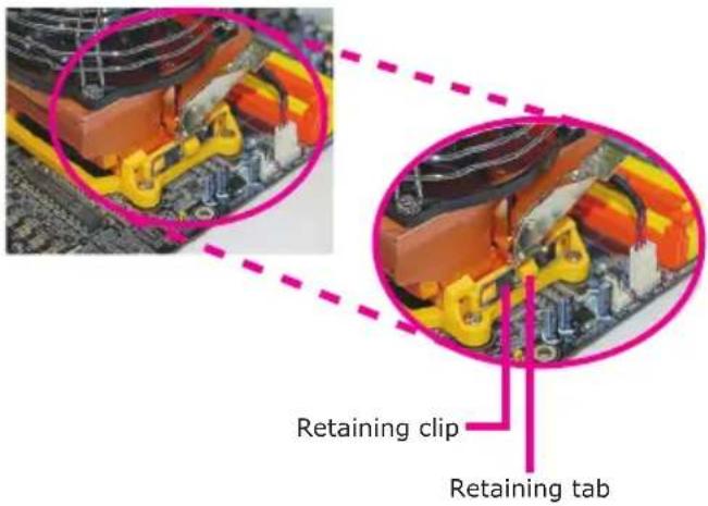
- Place the heat sink on top of the CPU. Now hook one side of the retention clip onto the retention module base by fitting the hole(s) on the retention clip into the retaining tab(s) of the retention module base.
Hook the other side of the retention clip so that the hole(s) on the retention clip also fit into the retaining tab(s) of the retention module base.
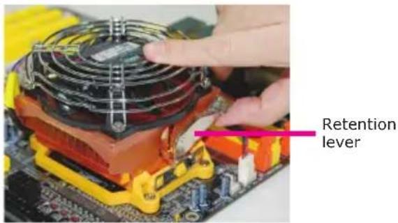
- Move the retention lever to its opposite side then push it down to lock the fan and heat sink assembly to the retention module base.

Note:
- You will not be able to secure the fan and heat sink assembly in place if it did not fit properly onto the retention module base.
-
Make sure there is sufficient air circulation across the CPU fan and heat sink.
-
Connect the CPU fan's cable connector to the CPU fan connector on the system board.
2
Hardware Installation
Northbridge Heat Sink
The Northbridge must be kept cool by using a heat sink. The heat sink will dissipate heat generated by the Northbridge. Without the heat sink, the Northbridge will overheat damaging both the Northbridge and the system board.
natural_image
Close-up of a computer motherboard with CPU socket, RAM slots, and memory chips (no readable text or symbols)Jumper Settings
Clear CMOS Data
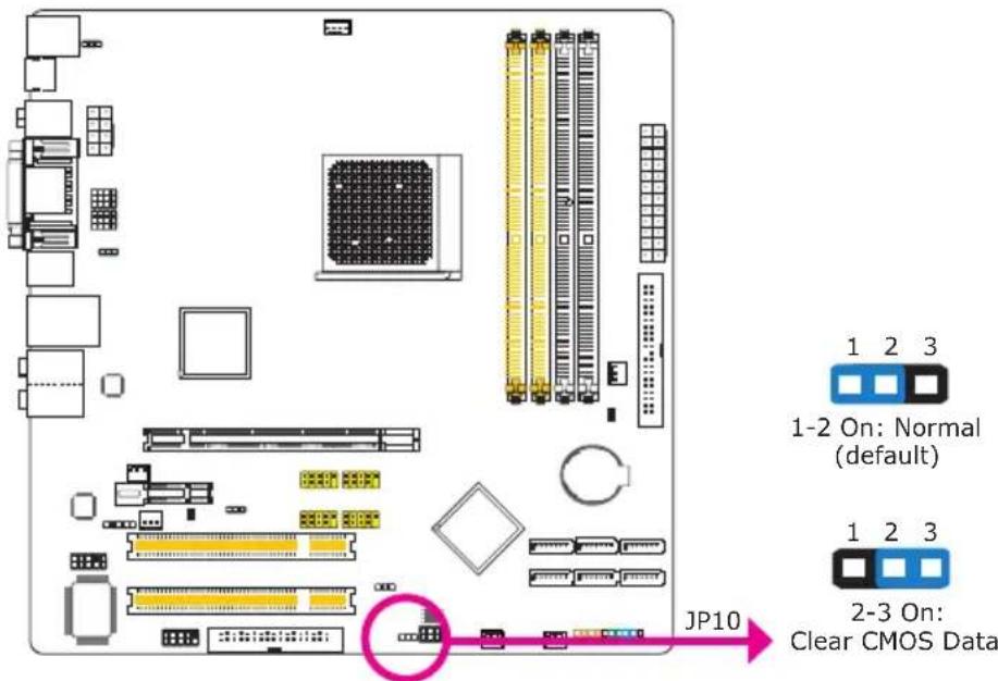
If you encounter the following,
a) CMOS data becomes corrupted.
b) You forgot the supervisor or user password.
c) The overclocked settings in the BIOS resulted to the system's instability or caused system boot up problems.
you can reconfigure the system with the default values stored in the ROM BIOS.
To load the default values stored in the ROM BIOS, please follow the steps below.
- Power-off the system then unplug the power cord.
- Set JP10 pins 2 and 3 to On. Wait for a few seconds and set JP10 back to its default setting, pins 1 and 2 On.
- Now plug the power cord then power-on the system.
PS/2 Power Select
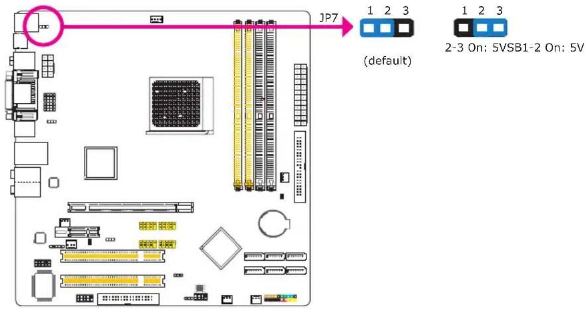
Selecting 5VSB will allow you to use the PS/2 keyboard or PS/2 mouse to wake up the system.

Important:
The 5VSB power source of your power supply must support ≥720mA.
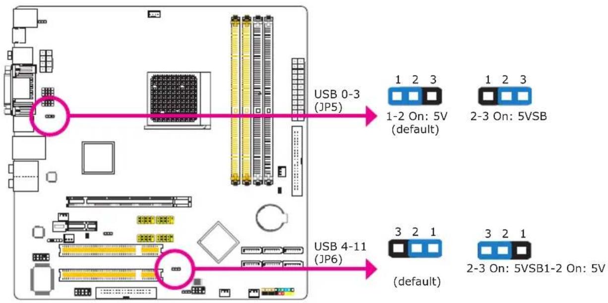
USB Power Select
flowchart
graph TD
    A["USB 0-3 (JP5)"] -->|1-2 On: 5V (default)| B["USB 4-11 (JP6)"]
    A -->|2-3 On: 5VSB| C["USB 4-11 (JP6)"]
    A -->|2-3 On: 5VSB1-2 On: 5V| D["USB 4-11 (JP6)"]
    style A fill:#f9f,stroke:#333
    style B fill:#ccf,stroke:#333
    style C fill:#cfc,stroke:#333
    style D fill:#fcc,stroke:#333
Selecting 5VSB will allow you to use the USB keyboard or USB mouse to wake up the system.

Important:
The 5VSB power source of your power supply must support ≥ 1.5A (2 devices) or ≥ 2A (3 or more devices).
PCIE Gen I / Gen 2 Select
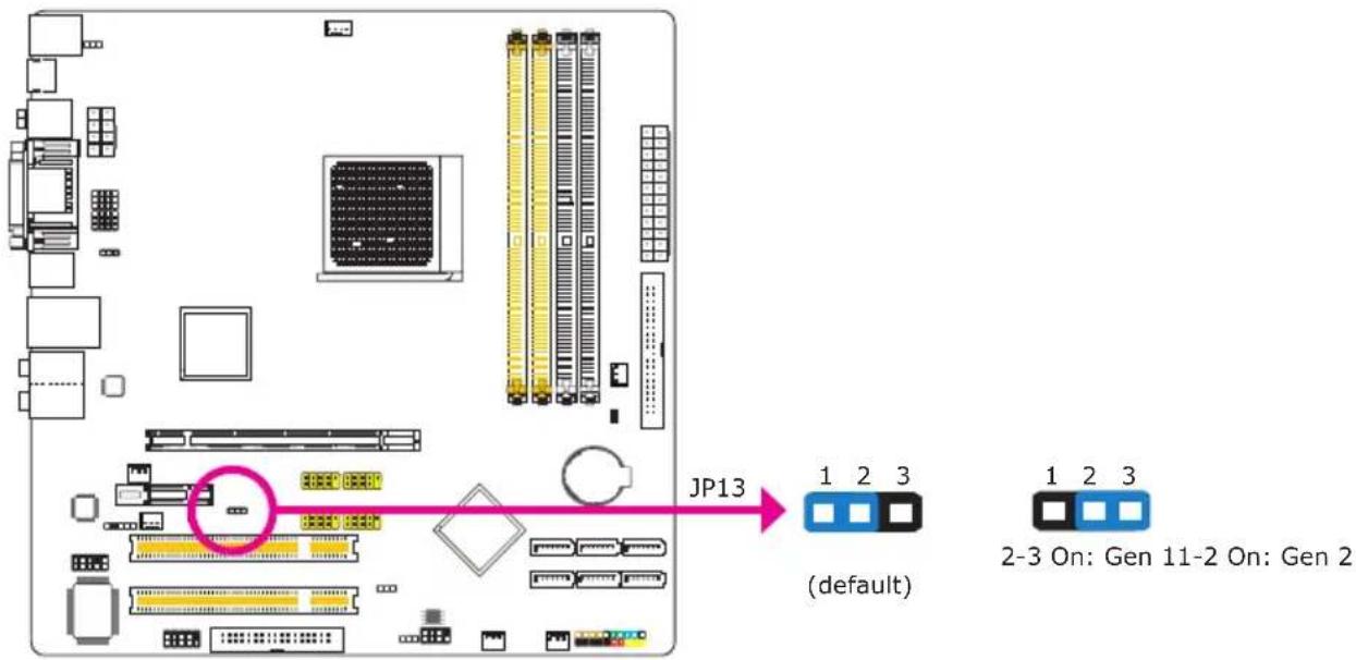
Set this jumper according to the type of PCI Express card that you are using.
HDMI/DVI Select
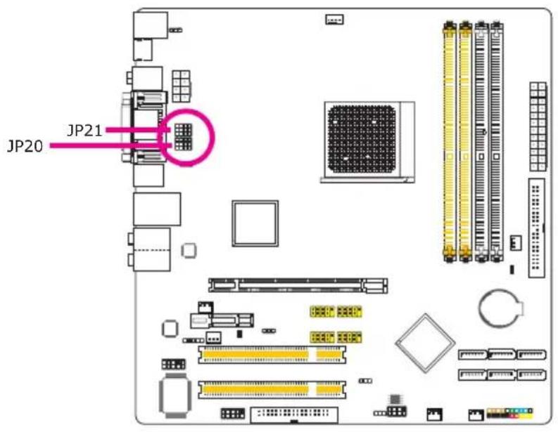
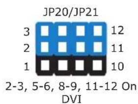
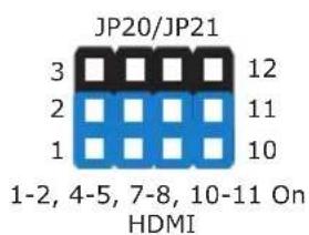
The system board is equipped with HDMI and DVI interfaces but you can only connect one display device at a time. Set this jumper according to the type of display device connected to the system.
Rear Panel I/O Ports
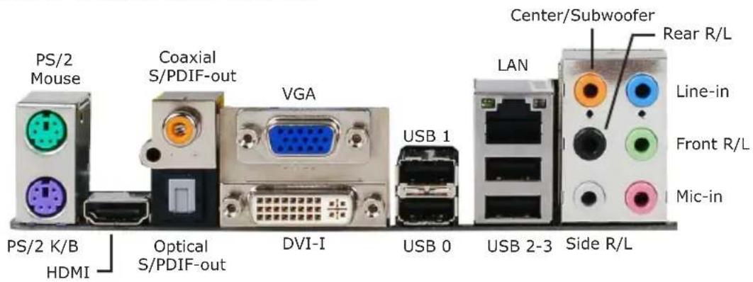
PS/2 Ports and S/PDIF Ports
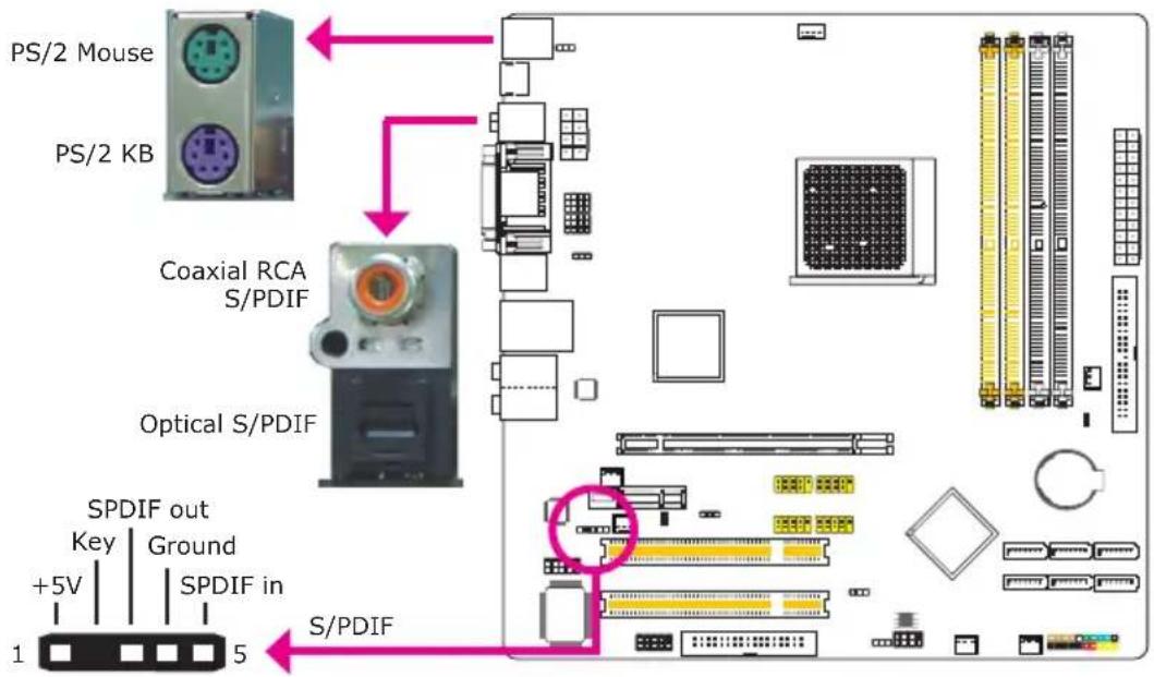
PS/2 Mouse and PS/2 Keyboard Ports
These ports are used to connect a PS/2 mouse and a PS/2 keyboard.
Optical S/PDIF
The optical S/PDIF jack is used to connect an external audio output device using an optical S/PDIF cable.
Coaxial RCA S/PDIF
The coaxial RCA S/PDIF jack is used to connect an external audio output device using a coaxial S/PDIF cable.

Important:
DO NOT use optical S/PDIF and Coaxial RCA S/PDIF at the same time.
S/PDIF Connector
The S/PDIF connector is used to connect an external S/PDIF port. Your S/PDIF port may be mounted on a card-edge bracket. Install the card-edge bracket to an available slot at the rear of the system chassis then connect the audio cable to the S/PDIF connector. Make sure pin 1 of the audio cable is aligned with pin 1 of the S/PDIF connector.
HDMI, VGA and DVI-I Ports
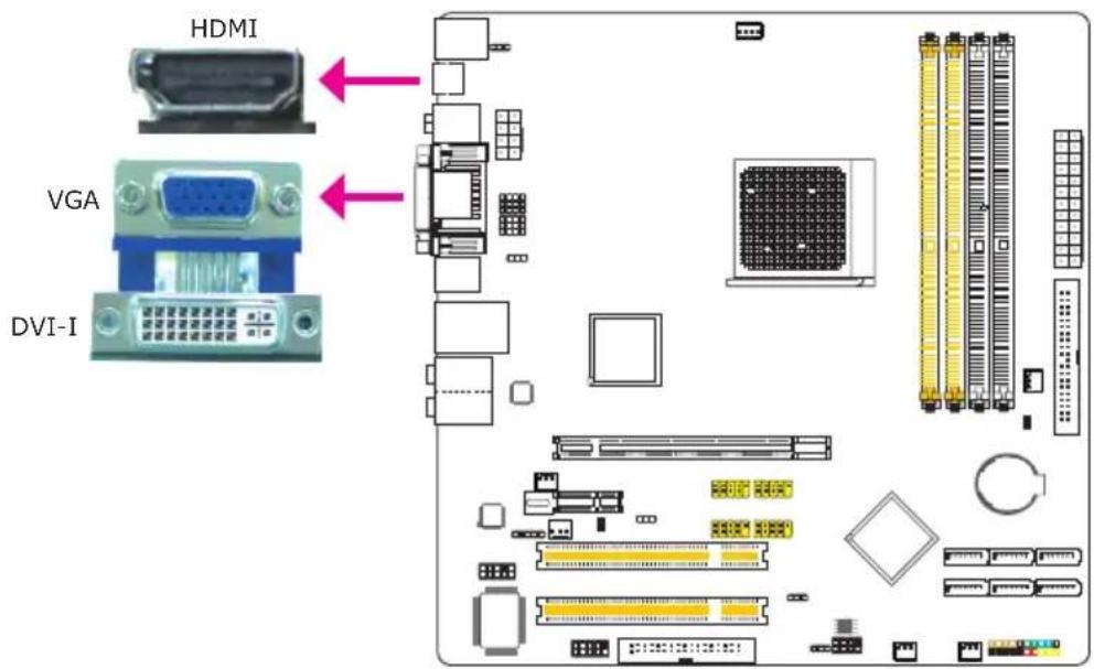
HDMI
The HDMI port which carries both digital audio and video signals is used to connect a LCD monitor or digital TV that has an HDMI port.
VGA
The VGA port is used for connecting a VGA monitor.
DVI-I
The DVI-I port is used to connect a digital LCD monitor or LCD TV. It supports DVI-D signal only.
USB and LAN Ports
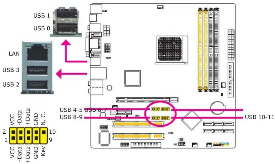
USB
The USB ports are used to connect USB 2.0/1.1 devices. The 10-pin connectors allow you to connect 8 additional USB 2.0/1.1 ports. Your USB ports may come mounted on a card-edge bracket. Install the card-edge bracket to an available slot at the rear of the system chassis then connect the USB port cables to these connectors.
LAN
The LAN port allows the system board to connect to a local area network by means of a network hub.
Audio
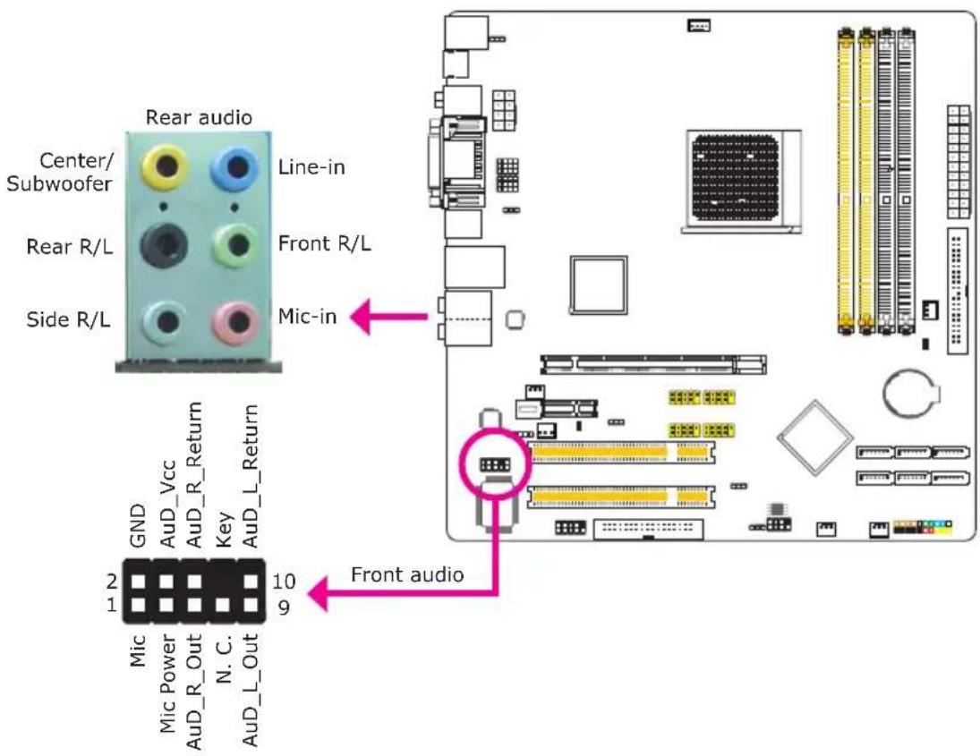
Rear Panel Audio
Center/Subwoofer Jack (Orange)•
This jack is used to connect to the center and subwoofer speakers of the audio system.
Rear Right/Left Jack (Black)•
This jack is used to connect to the rear right and rear left speakers of the audio system.
Side Right/Left Jack (Gray)•
This jack is used to connect to the side left and side right speakers of the audio system.
Line-in (Light Blue)•
This jack is used to connect any audio devices such as Hi-fi set, CD player, tape player, AM/FM radio tuner, synthesizer, etc.
Line-out - Front Right/Left Jack (Lime)•
This jack is used to connect to the front right and front left speakers of the audio system.
Mic-in Jack (Pink)•
This jack is used to connect an external microphone.
Front Audio
The front audio connector is used to connect to the line-out and mic-in jacks that are at the front panel of your system.
Internal I/O Connectors
Serial ATA Connectors
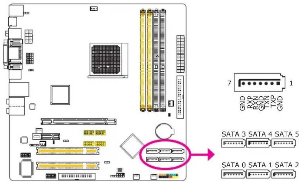
The Serial ATA (SATA) connectors are used to connect Serial ATA drives. Connect one end of the Serial ATA cable to a Serial ATA connector and the other end to your Serial ATA device.
Configuring RAID
Refer to the RAID chapter in this manual for more information about creating RAID on Serial ATA drives.
FDD Connector and IDE Connector
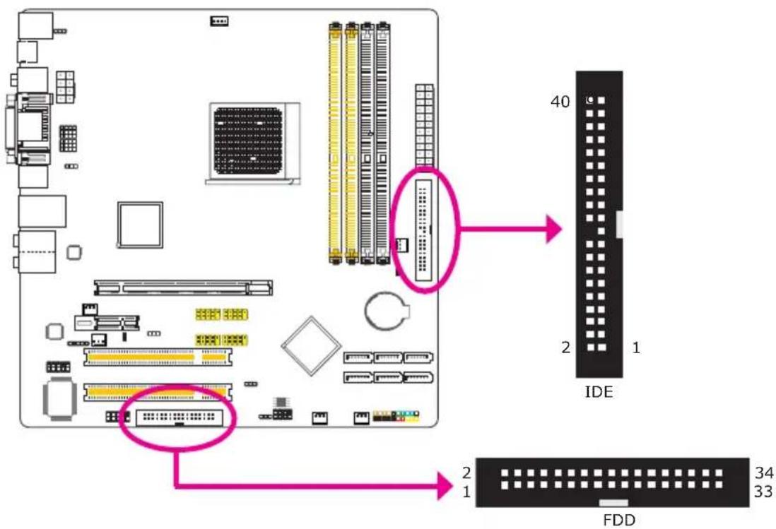
FDD Connector
The floppy disk drive connector is used to connect a floppy drive. Insert one end of the floppy cable into this connector and the other end-most connector to the floppy drive. The colored edge of the cable should align with pin 1 of this connector.
IDE Connector
The IDE disk drive connector is used to connect 2 IDE disk drives. An IDE cable have 3 connectors on them, one that plugs into this connector and the other 2 connects to IDE devices. The connector at the end of the cable is for the Master drive and the connector in the middle of the cable is for the Slave drive. The colored edge of the cable should align with pin 1 of this connector.

Note:
When using two IDE drives, one must be set as the master and the other as the slave. Follow the instructions provided by the drive manufacturer for setting the jumpers and/or switches on the drives.
Serial (COM) Connector
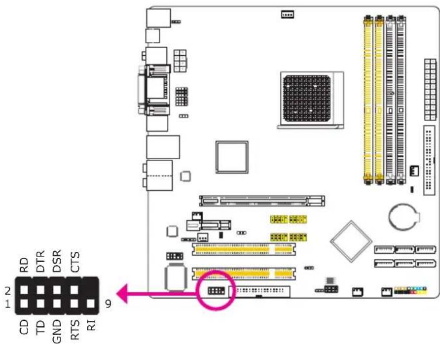
The serial (COM) connector is used to connect modems, serial printers, remote display terminals, or other serial devices. Your COM port may come mounted on a card-edge bracket. Install the card-edge bracket to an available slot at the rear of the system chassis then connect the serial port cable to this connector. The colored edge of the cable should align with pin 1 of this connector.
Cooling Fan Connectors
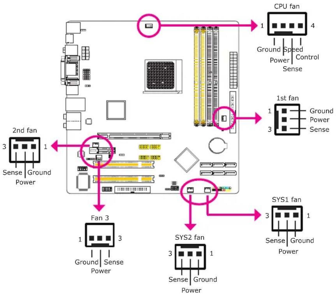
flowchart
graph TD
    A["CPU fan"] -->|1 Ground Speed Control Sense| B["2nd fan"]
    A -->|4 Power| C["1st fan"]
    B -->|Sense Ground Power| D["Fan 3"]
    C -->|Sense Ground Power| E["SYS1 fan"]
    D -->|Sense Ground Power| F["SYS2 fan"]
    E -->|Sense Ground Power| G["End"]
These fan connectors are used to connect cooling fans. Cooling fans will provide adequate airflow throughout the chassis to prevent overheating the CPU and system board components.
LEDs
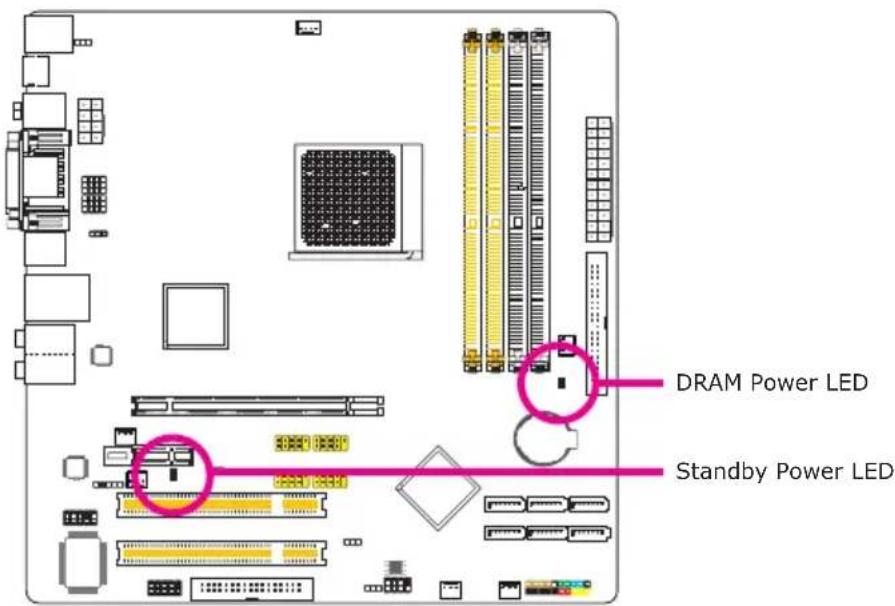
DRAM Power LED
This LED will light when the system's power is on.
Standby Power LED
This LED will light when the system is in the standby mode.

Important:
When the DRAM Power LED and/or Standby Power LED lit red, it indicates that power is present on the DIMM sockets and/or PCI slots. Power-off the PC then unplug the power cord prior to installing any memory modules or add-in cards. Failure to do so will cause severe damage to the motherboard and components.
Power Connectors
Use a power supply that complies with the ATX12V Power Supply Design Guide Version 1.1. An ATX12V power supply unit has a standard 24-pin ATX main power connector that must be inserted into this connector.
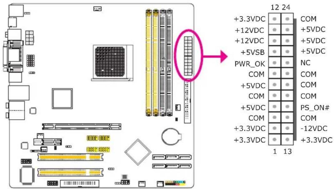
Your power supply unit may come with an 8-pin or 4-pin +12V power connector. The +12V power enables the delivery of more +12VDC current to the processor's Voltage Regulator Module (VRM). If available, it is preferable to use the 8-pin power; otherwise connect a 4-pin power to this connector.
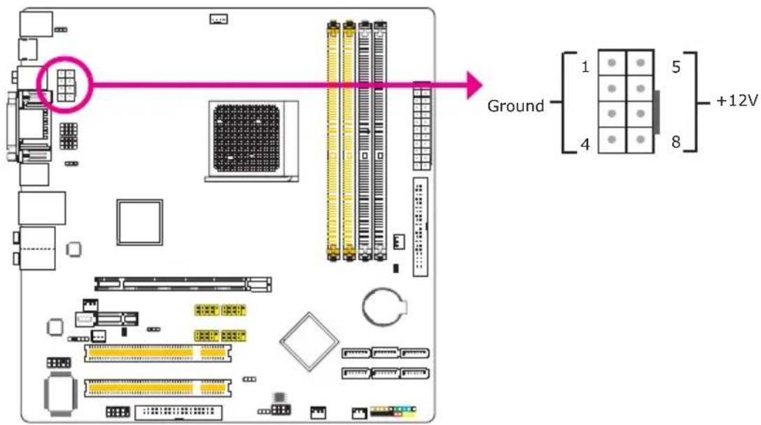
The power connectors from the power supply unit are designed to fit the 24-pin and 8-pin connectors in only one orientation. Make sure to find the proper orientation before plugging the connectors.
The system board requires a minimum of 300 Watt power supply to operate. Your system configuration (CPU power, amount of memory, add-in cards, peripherals, etc.) may exceed the minimum power requirement. To ensure that adequate power is provided, we strongly recommend that you use a minimum of 400 Watt (or greater) power supply.

Important:
Insufficient power supplied to the system may result in instability or the add-in boards and peripherals not functioning properly. Calculating the system's approximate power usage is important to ensure that the power supply meets the system's consumption requirements.
Restarting the PC
Normally, you can power-off the PC by:
- Pressing the power button at the front panel of the chassis.
or
- Pressing the power switch that is on the system board (note: not all system boards come with this switch).
If for some reasons you need to totally cut off the power supplied to the PC, switch off the power supply or unplug the power cord. Take note though that if you intend to restart it at once, please strictly follow the steps below.
-
The time where power is totally discharged varies among power supplies. It's discharge time is highly dependent on the system's configuration such as the wattage of the power supply, the sequence of the supplied power as well as the number of peripheral devices connected to the system. Due to this reason, we strongly recommend that you wait for the Standby Power LED (refer to the "LEDs" section in this chapter for the location of the Standby Power LED) to lit off.
-
After the Standby Power LED has lit off, wait for 6 seconds before powering on the PC.
If the system board is already enclosed in a chassis which apparently will not make the Standby Power LED visible, wait for 15 seconds before you restore power connections. 15 seconds is approximately the time that will take the LED to lit off and the time needed before restoring power.
The above will ensure protection and prevent damage to the motherboard and components.
Front Panel Connectors
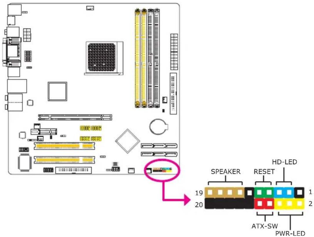
HD-LED: Primary/Secondary IDE LED
This LED will light when the hard drive is being accessed.
RESET: Reset Switch
This switch allows you to reboot without having to power off the system thus prolonging the life of the power supply or system.
SPEAKER: Speaker Connector
This connects to the speaker installed in the system chassis.
ATX-SW: ATX Power Switch
Depending on the setting in the BIOS setup, this switch is a "dual function power button" that will allow your system to enter the Soft-Off or Suspend mode.
PWR-LED: Power/Standby LED
When the system's power is on, this LED will light. When the system is in the S1 (POS - Power On Suspend) or S3 (STR - Suspend To RAM) state, it will blink every second.

Note:
If a system did not boot-up and the Power/Standby LED did not light after it was powered-on, it may indicate that the CPU or memory module was not installed properly. Please make sure they are properly inserted into their corresponding socket.
| Pin | Pin Assignment | |
| HD-LED(Primary/Secondary IDE LED) | 35 | HDD LED PowerHDD |
| Reserved | 1416 | N. C.N. C. |
| ATX-SW(ATX power switch) | 810 | PWRBT+PWRBT- |
| Reserved | 1820 | N. C.N. C. |
| RESET(Reset switch) | 79 | GroundH/W Reset |
| SPEAKER(Speaker connector) | 13151719 | Speaker DataN. C.GroundSpeaker Power |
| PWR-LED(Power/Standby LED) | 246 | LED Power (+)LED Power (+)LED Power (-) or Standby Signal |
PCI Express Slots
Download Flash BIOS Connector
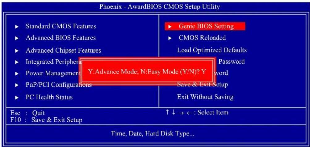
Aimed to provide convenience and superb overclockability, the Genie BIOS Setting submenu comes available in Easy mode (default mode) and Advance mode.
Easy Mode
Easy mode displays fields commonly used by users.
Advance Mode
If you intend to tweak your PC or boost its overclock feature, you can switch the Genie BIOS Setting submenu from Easy mode to Advance mode by simply pressing
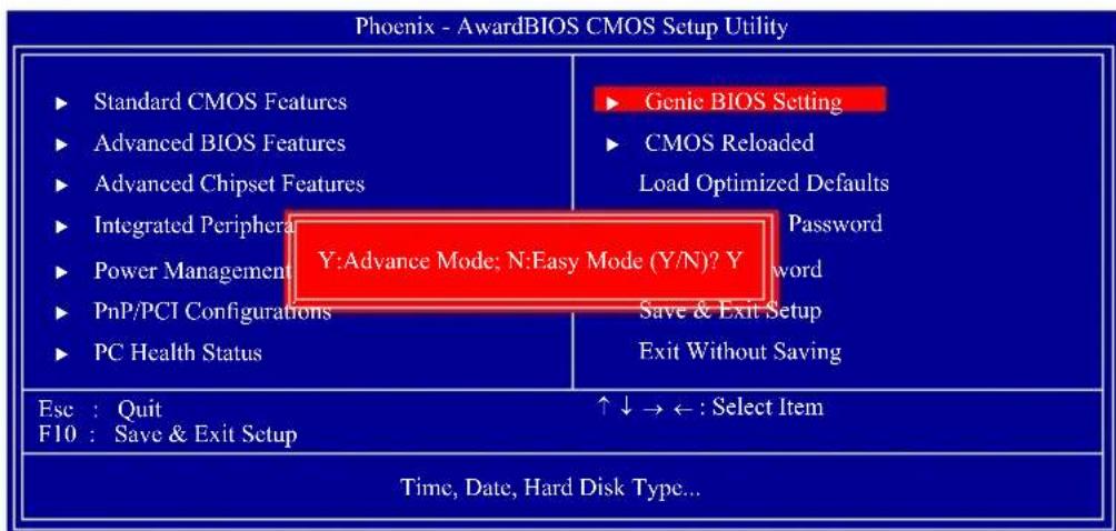
Award BIOS Setup Utility
The Basic Input/Output System (BIOS) is a program that takes care of the basic level of communication between the processor and peripherals. In addition, the BIOS also contains codes for various advanced features found in this system board. This chapter explains the Setup Utility for the Award BIOS.
After you power up the system, the BIOS message appears on the screen and the memory count begins. After the memory test, the following message will appear on the screen:
Press DEL to enter setup
If the message disappears before you respond, restart the system or press the "Reset" button. You may also restart the system by pressing the keys simultaneously.
When you press , the main menu screen will appear.
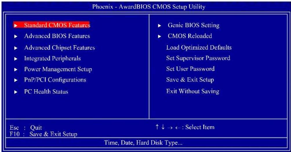
Standard CMOS Features
Use the arrow keys to highlight "Standard CMOS Features" then press
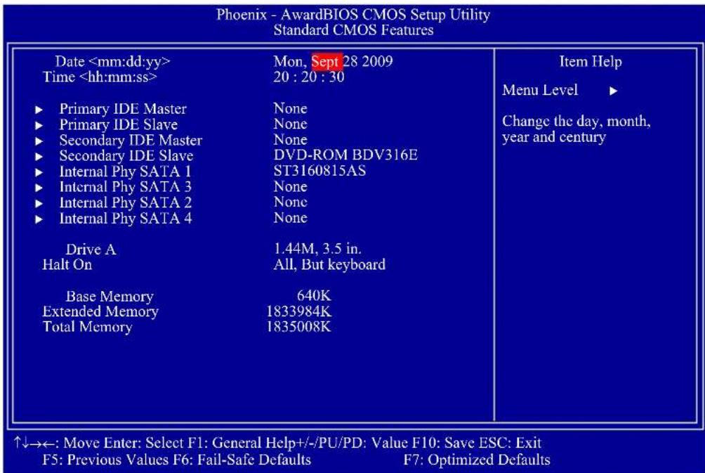
The settings on the screen are for reference only. Your version may not be identical to this one.
Date
The date format is
Time
The time format is
Primary IDE Master to Secondary IDE Slave
These fields are used to configure Parallel ATA drives. Move the cursor to a field then press
| Phoenix - AwardBIOS CMOS Setup Utility Primary IDE Master | ||
| IDE HDD Auto-Detection | Press Enter | Item Help |
| Primary IDE Master Access Mode | Auto Auto | Menu Level ▶▶ |
| Capacity | 0 MB | To auto-detect the HDD's size, head... on this channel |
| Cylinder | 0 | |
| Head | 0 | |
| Precomp | 0 | |
| Landing Zone | 0 | |
| Sector | 0 | |
The settings on the screen are for reference only. Your version may not be identical to this one.
IDE HDD Auto-Detection
Detects the parameters of the drive. The parameters will automatically be shown on the screen.
Primary IDE Master to Secondary IDE Slave
If you select "Auto", the BIOS will auto-detect the HDD & CD-ROM drive at the POST stage and show the IDE for the HDD & CD-ROM drive. If a hard disk has not been installed, select "None".
Access Mode
For hard drives larger than 528MB, you would typically select the LBA type. Certain operating systems require that you select CHS or Large. Please check your operating system's manual or Help desk on which one to select.
Capacity
Displays the approximate capacity of the disk drive. Usually the size is slightly greater than the size of a formatted disk given by a disk checking program.
Cylinder
This field displays the number of cylinders.
Head
This field displays the number of read/write heads.
Precomp
This field displays the number of cylinders at which to change the write timing.
Landing Zone
This field displays the number of cylinders specified as the landing zone for the read/write heads.
Sector
This field displays the number sectors per track.
Internal Phy SATA 1 to Internal Phy SATA 4
These fields are used to configure Serial ATA drives. Move the cursor to a field then press

Note:
The fields for configuring Serial ATA drives will appear only if the Serial ATA function is Enabled. Enable this function in the Integrated Peripherals submenu of the BIOS.
| Phoenix - AwardBIOS CMOS Setup Utility Internal Phy SATA 1 | ||
| IDE Auto-Detection | Press Enter | Item Help |
| Extended IDE Drive Access Mode | Auto Auto | Menu Level ▶▶ |
| Capacity | 0 MB | To auto-detect the HDD's size, head... on this channel |
| Cylinder | 0 | |
| Head | 0 | |
| Precomp | 0 | |
| Landing Zone | 0 | |
| Sector | 0 | |
The settings on the screen are for reference only. Your version may not be identical to this one.
Drive A
This field identifies the type of floppy disk drive installed.
None
No floppy drive is installed
360K, 5.25 in.
5-1/4 in. standard drive; 360KB capacity
1.2M, 5.25 in.
5-1/4 in. AT-type high-density drive; 1.2MB capacity
720K, 3.5 in.
3-1/2 in. double-sided drive; 720KB capacity
1.44M, 3.5 in.
3-1/2 in. double-sided drive; 1.44MB capacity
2.88M, 3.5 in.
3-1/2 in. double-sided drive; 2.88MB capacity
Halt On
This field determines whether the system will stop if an error is detected during power up. The default setting is All Errors.
No Errors
The system boot will not stop for any errors detected.
All Errors
The system boot will stop whenever the BIOS detects a non-fatal error.
All, But Keyboard
The system boot will not stop for a keyboard error; it will stop for all other errors.
All, But Diskette
The system boot will not stop for a disk error; it will stop for all other errors.
All, But Disk/Key
The system boot will not stop for a disk or keyboard error; it will stop for all other errors.
Base Memory
Displays the amount of base (or conventional) memory installed in the system. The value of the base memory is typically 512K for systems with 512K memory installed on the motherboard or 640K for systems with 640K or more memory installed on the motherboard.
Extended Memory
Displays the amount of extended memory detected during boot-up.
Total Memory
Displays the total memory available in the system.
Advanced BIOS Features
The Advanced BIOS Features allows you to configure your system for basic operation. Some entries are defaults required by the system board, while others, if enabled, will improve the performance of your system or let you set some features according to your preference.
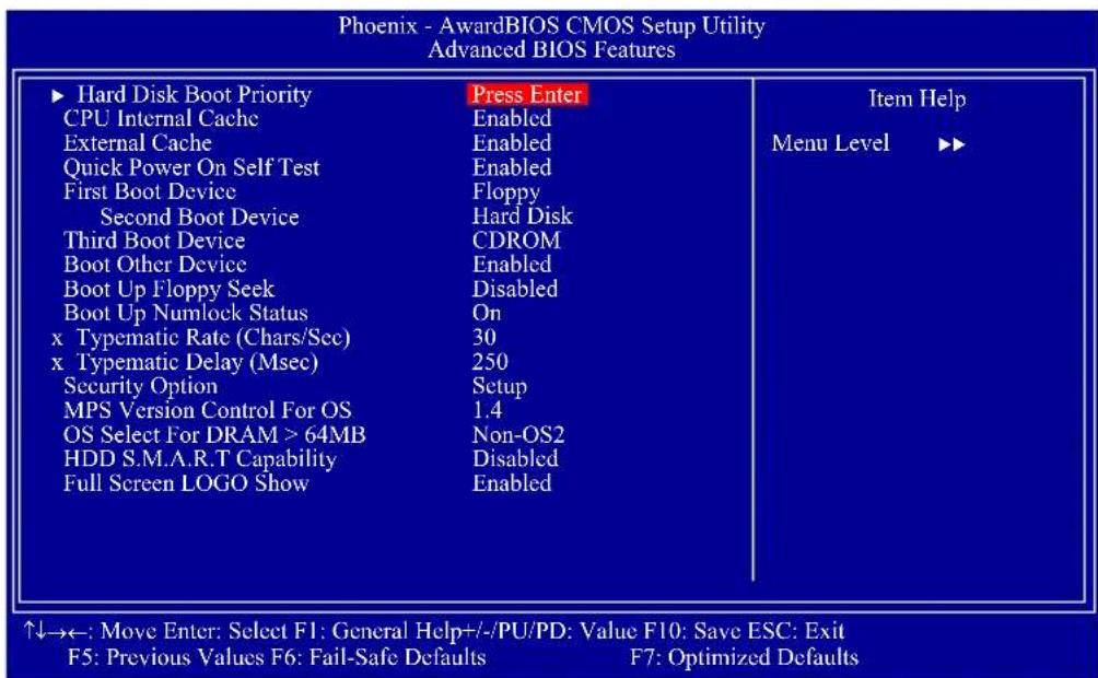
The settings on the screen are for reference only. Your version may not be identical to this one.
Hard Disk Boot Priority
Refer to the next section for more information on this submenu.
CPU Internal Cache and External Cache
These fields speed up the memory access. The default is Enabled, which provides better performance by enabling cache.
Quick Power On Self Test
This field speeds up Power On Self Test (POST) whenever the system is powered on. The BIOS will shorten or skip some check items during POST. To attain the shortest POST time, select "Fast".
First Boot Device, Second Boot Device, Third Boot Device and Boot Other Device
Select the drive to boot first, second and third in the "First Boot Device" "Second Boot Device" and "Third Boot Device" fields respectively. The BIOS will boot the operating system according to the sequence of the drive selected. Set "Boot Other Device" to Enabled if you wish to boot from another device.
Boot Up Floppy Seek
When enabled, the BIOS will check whether the floppy disk drive installed is 40 or 80 tracks. Note that the BIOS cannot distinguish between 720K, 1.2M, 1.44M and 2.88M drive types as they are all 80 tracks. When disabled, the BIOS will not search for the type of floppy disk drive by track number. Note that there will not be any warning message if the drive installed is 360KB.
Boot Up NumLock Status
This allows you to determine the default state of the numeric keypad. By default, the system boots up with NumLock on wherein the function of the numeric keypad is the number keys. When set to Off, the function of the numeric keypad is the arrow keys.
Typematic Rate (Chars/Sec)
This field allows you to select the rate at which the keys are accelerated.
Typematic Delay (Msec)
This field allows you to select the delay between when the key was first depressed and when the acceleration begins.
Security Option
This field determines when the system will prompt for the password- everytime the system boots or only when you enter the BIOS setup. Set the password in the Set Supervisor/User Password submenu.
System
The system will not boot and access to Setup will be denied unless the correct password is entered at the prompt.
Setup
The system will boot, but access to Setup will be denied unless the correct password is entered at the prompt.
MPS Version Control for OS
This field is used to select the MPS version that the system board is using.
OS Select for DRAM > 64MB
This field allows you to access the memory that is over 64MB in OS/2.
HDD S.M.A.R.T Capability
The system board supports SMART (Self-Monitoring, Analysis and Reporting Technology) hard drives. SMART is a reliability prediction technology for ATA/IDE and SCSI drives. The drive will provide sufficient notice to the system or user to backup data prior to the drive's failure. The default is Disabled. If you are using hard drives that support S.M.A.R.T., set this field to Enabled. SMART is supported in ATA/33 or later hard drives.
Full Screen Logo Show
This field is applicable only if you want a particular logo to appear during system boot-up.
Enabled
The logo will appear in full screen during system boot-up.
Disabled
The logo will not appear during system boot-up.
Hard Disk Boot Priority
This field is used to select the boot sequence of the hard drives. Move the cursor to this field then press
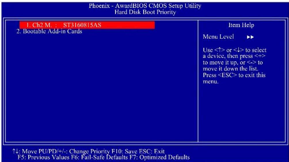
The settings on the screen are for reference only. Your version may not be identical to this one.
Advanced Chipset Features
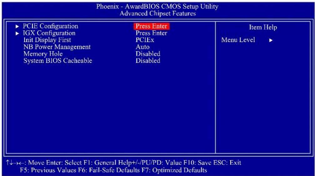
The settings on the screen are for reference only. Your version may not be identical to this one.
This section gives you functions to configure the system based on the specific features of the chipset. The chipset manages bus speeds and access to system memory resources. These items should not be altered unless necessary. The default settings have been chosen because they provide the best operating conditions for your system. The only time you might consider making any changes would be if you discovered some incompatibility or that data was being lost while using your system.
PCIE Configuration IGX Configuration
Refer to the following pages for more information on these submenus.
Init Display First
IGX
When the system boots, it will first initialize the onboard VGA.
PCIEx
When the system boots, it will first initialize the PCI Express x16 graphics card.
NB Power Management
Dynamic clock gating for IOC/NT/MCU/CFG. The options are Auto, Enabled and Disabled.
Memory Hole
In order to improve system performance, certain space in memory can be reserved for ISA cards. This memory must be mapped into the memory space below 16MB. When enabled, the CPU assumes the 15-16MB memory range is allocated to the hidden ISA address range instead of the actual system DRAM. When disabled, the CPU assumes the 15-16MB address range actually contains DRAM memory. If more than 16MB of system memory is installed, this field must be disabled to provide contiguous system memory.
System BIOS Cacheable
When this field is enabled, accesses to the system BIOS ROM addressed at F0000H-FFFFFFH are cached, provided that the cache controller is enabled. The larger the range of the Cache RAM, the higher the efficiency of the system.
PCIE Configuration
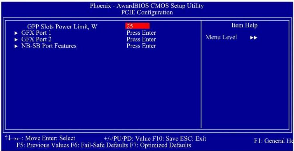
The settings on the screen are for reference only. Your version may not be identical to this one.
GPP Slots Power Limit, W
This field is used to enter the GPP's power limit. The minimum is 0 and the maximum is 255.
GFX Port 1 / GFX Port 2
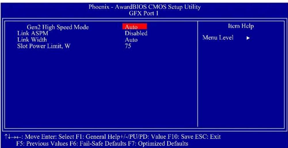
The settings on the screen are for reference only. Your version may not be identical to this one.
Gen2 High Speed Mode
The options are Auto, Disabled, Software Initiated and Advertised RC.
Link ASPM
The options are Disabled, L0s, L1, and L0s & L1.
Link Width
The options are Auto, x1, x2, x4 and x8.
Slot Power Limit,W
This field is used to enter the slot's power limit. The minimum is 0 and the maximum is 255.
NB-SB Port Features
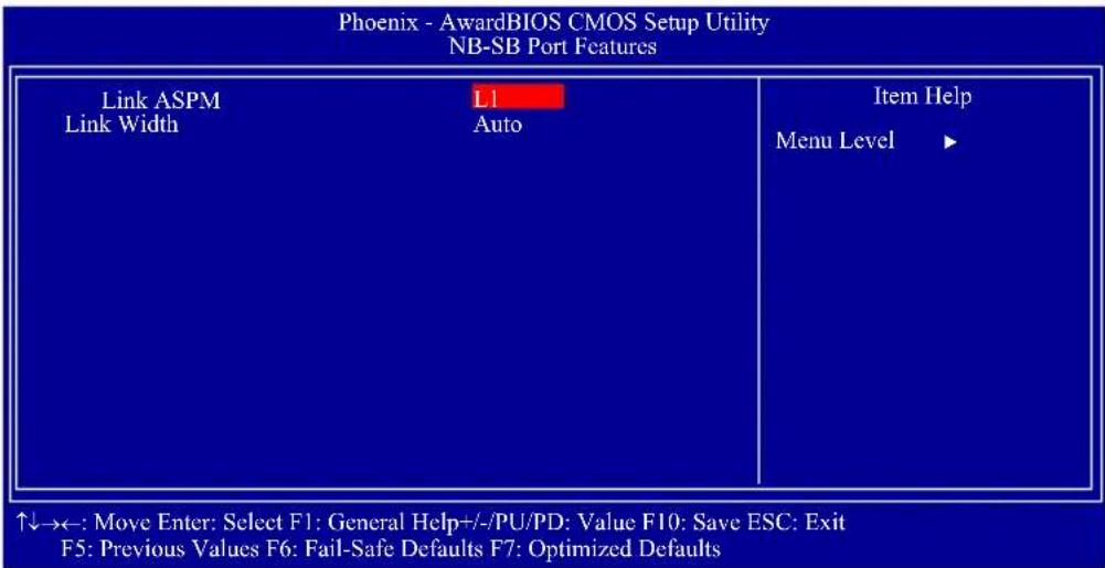
The settings on the screen are for reference only. Your version may not be identical to this one.
Link ASPM
The options are Disabled and L1.
Link Width
The options are Auto, x1, x2 and x4.
IGX Configuration
| Internal Graphics Mode UMA Frame Buffer Size Frame Buffer Location IGX Engine Clock Override IGX Engine Clock HDMI Audio | UMA+SidePort Auto Above 4G Enabled 700 Disabled | Item Help Menu Level ▶ |
| Surround View | Auto | |
| SidePort Clock Speed UMA-SP Interleave Mode x Size x Ratio (SP:UMA) SP Power Management SP NB Termination SP Memory Termination | 667MHz Auto Auto Auto Auto Enabled Enabled |
The settings on the screen are for reference only. Your version may not be identical to this one.
Internal Graphics Mode
This is used to configure the internal graphics mode. The options are Disabled, UMA and UMA+SidePort.
UMA Frame Buffer Size
This is used to select the total amount of system memory locked by the BIOS for video. A larger frame buffer size should result in higher video performance. The options are Auto, 32MB, 64MB, 128MB, 256MB and 512MB.
Frame Buffer Location
This is used to select the frame buffer's location. The options are Below 4G and Above 4G.
IGX Engine Clock Override
The options are Enabled and Disabled.
IGX Engine Clock
This is used to enter the IGX engine clock. The minimum is 150 and the maximum is 1000.
HDMI Audio
This is used to enable or disable the HDMI audio.
Surround View
The options are Auto, Enabled and Disabled.
SidePort Clock Speed
This is used to select the SidePort's clock speed. The options are 400MHz, 533MHz and 667MHz.
UMA-SP Interleave Mode
The options are Auto and Fine.
Size
The options are Auto, 4MB, 8MB, 16MB, 32MB, 64MB and 128MB.
Ratio (SP:UMA)
The options are Auto, 1:1, 1:3, 1:7, 1:15, 3:5, 3:13, 5:11 and 7:9.
SP Power Management
The options are Auto, Dynamic CKE, Dynamic CMD, Dynamic CLK and Disable.
SP NB Termination
The options are Auto, Disabled and Enabled.
SP Memory Termination
The options are Auto, Disabled and Enabled.
Integrated Peripherals
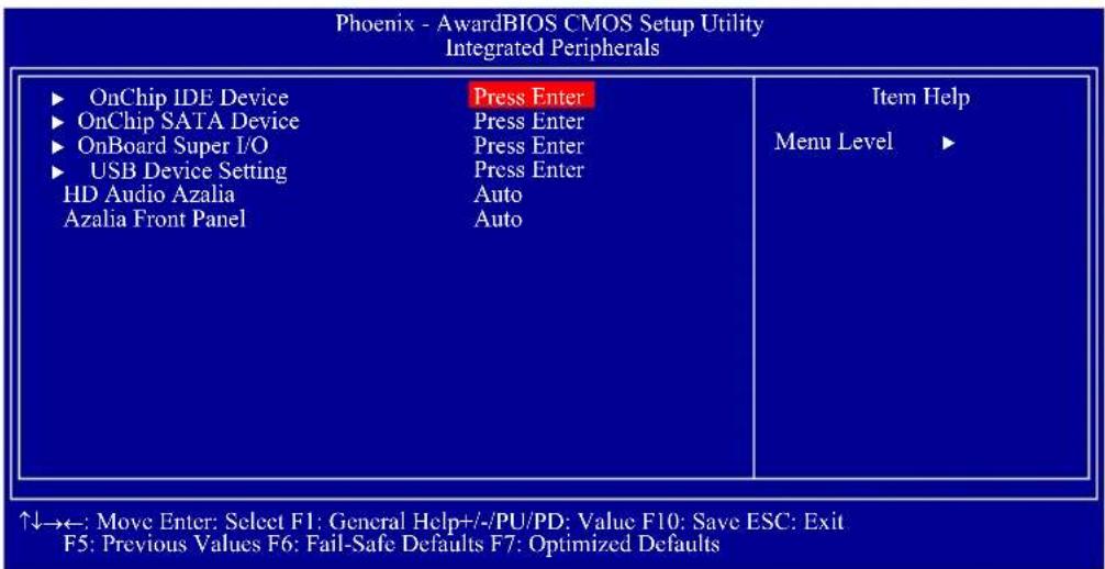
The settings on the screen are for reference only. Your version may not be identical to this one.
OnChip IDE Device OnChip SATA Device OnBoard Super I/O USB Device Setting
Refer to the following pages for more information on these submenus.
HD Audio Azalia
This field is used to enable or disable the onboard HD audio.
Azalia Front Panel
This field is used to enable or disable the Azalia front panel audio.
OnChip IDE Device
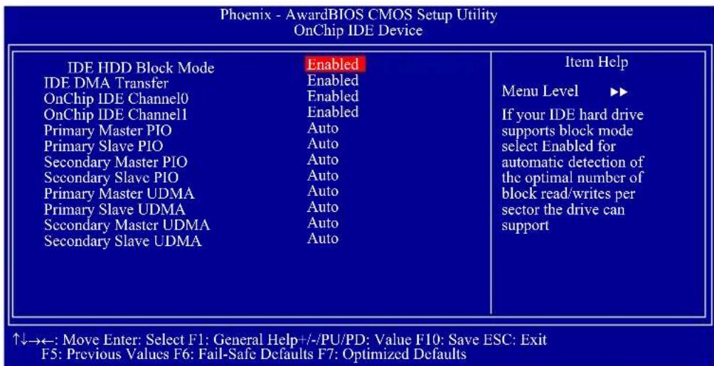
The settings on the screen are for reference only. Your version may not be identical to this one.
IDE HDD Block Mode
Enabled
The IDE HDD uses the block mode. The system BIOS will check the hard disk drive for the maximum block size the system can transfer. The block size will depend on the type of hard disk drive.
Disabled
The IDE HDD uses the standard mode.
IDE DMA Transfer
Enabled
The IDE HDD uses the block mode. The system BIOS will check the hard disk drive for the maximum block size the system can transfer. The block size will depend on the type of hard disk drive.
Disabled
The IDE HDD uses the standard mode.
OnChip IDE Channel 0 and OnChip IDE Channel 1
These fields allow you to enable or disable the primary and secondary IDE controller. The default is Enabled. Select Disabled if you want to add a different hard drive controller.
Primary Master/Slave PIO to Secondary Master/Slave PIO
PIO means Programmed Input/Output. Rather than have the BIOS issue a series of commands to effect a transfer to or from the disk drive, PIO allows the BIOS to tell the controller what it wants and then let the controller and the CPU perform the complete task by themselves. Your system supports five modes, 0 (default) to 4, which primarily differ in timing. When Auto is selected, the BIOS will select the best available mode after checking your drive.
Auto
The BIOS will automatically set the system according to your hard disk drive's timing.
Mode 0-4
You can select a mode that matches your hard disk drive's timing. Caution: Do not use the wrong setting or you will have drive errors.
Primary Master/Slave UDMA to Secondary Master/Slave UDMA
These fields allow you to set the Ultra DMA in use. When Auto is selected, the BIOS will select the best available option after checking your hard drive or CD-ROM.
Auto
The BIOS will automatically detect the settings for you.
Disabled
The BIOS will not detect these categories.
OnChip SATA Device
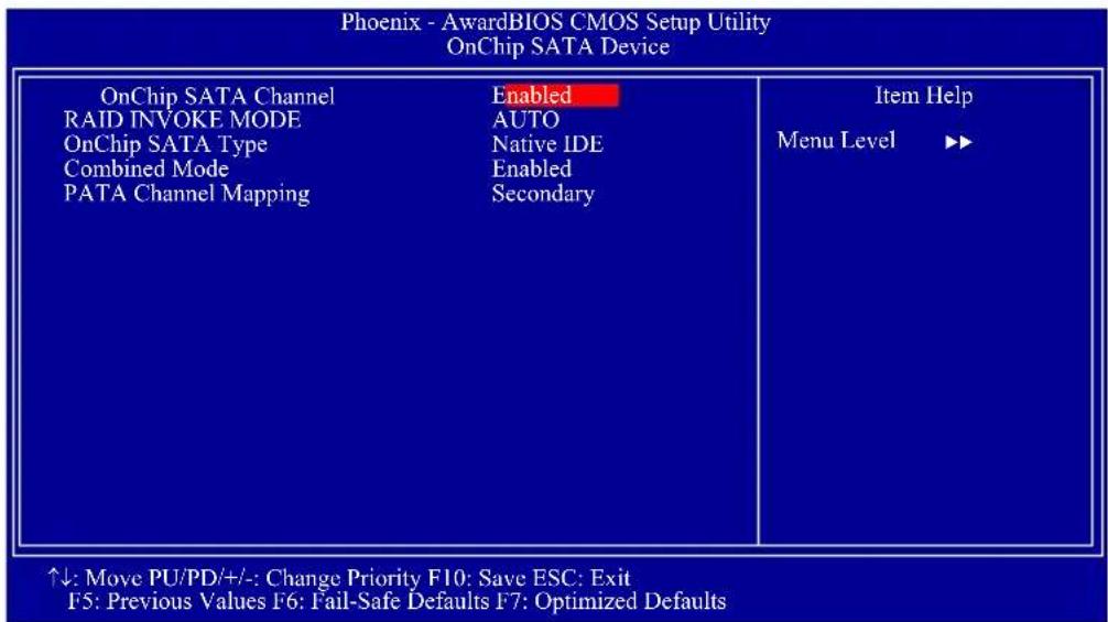
The settings on the screen are for reference only. Your version may not be identical to this one.
OnChip SATA Channel
This field is used to enable or disable the onboard SATA.
RAID Invoke Mode
The options are Auto, Biggest First and Smallest First.
OnChip SATA Type
This field is used to configure the SATA devices supported by the south-bridge.
Native IDE
This option configures the Serial ATA drives as Parallel ATA storage devices.
RAID
This option allows you to create RAID on Serial ATA devices.
AHCI
This option allows the Serial ATA devices to use AHCI (Advanced Host Controller Interface).
Legacy IDE
This option configures the Serial ATA drives as Legacy IDE storage devices.
Combined Mode
This field is used to enable or disable the combined mode.
PATA Channel Mapping
The options are Primary and Secondary.
Onboard Super IO
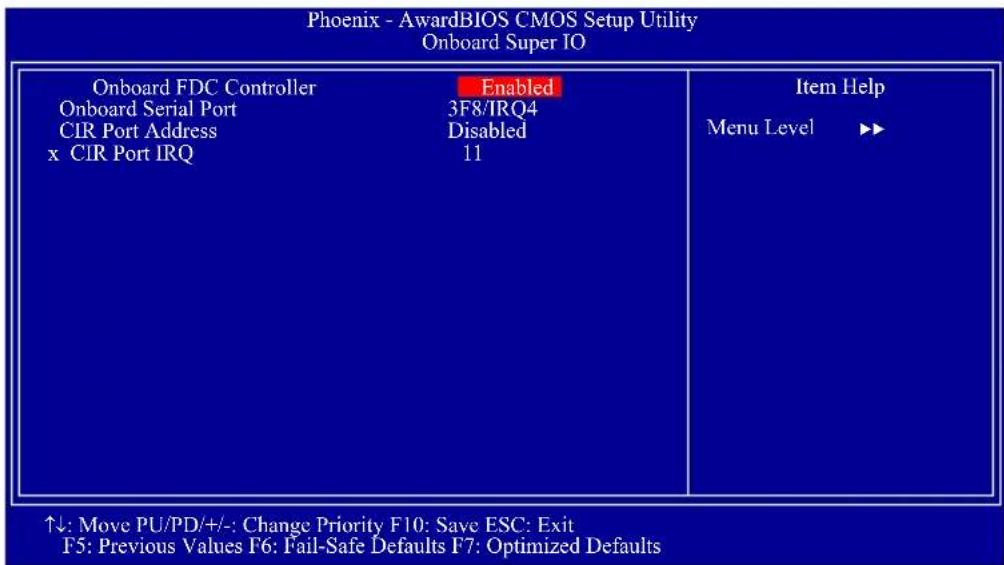
The settings on the screen are for reference only. Your version may not be identical to this one.
Onboard FDC Controller
Enabled
Enables the onboard floppy disk controller.
Disabled
Disables the onboard floppy disk controller.
Onboard Serial Port
3F8/IRQ4, 2F8/IRQ3, 3E8/IRQ4, 2E8/IRQ3
Allows you to manually select an I/O address for the onboard serial port.
Disabled
Disables the onboard serial port.
CIR Port Address
This field is used to select an I/O address for the CIR device.
CIR Port IRQ
This field is used to select an IRQ for the CIR device.
USB Device Setting
![Phoenix - AwardBIOS CMOS Setup Utility USB Device Setting USB 2.0 Controller 1 Enabled USB 2.0 Controller 2 Enabled USB 1.0 Controller Enabled USB Keyboard Function Enabled USB Mouse Function Enabled USB Storage Function Enabled *** USB Mass Storage Device Boot Setting *** Item Help Menu Level ▶▶ [Enable] or [Disable] Universal Host Controller Interfacefor Universal Serial Bus USB Operation Mode ↑↓→←: Move Enter: Select F1: General Help+/-/PU/PD: Value F10: Save ESC: Exit F5: Previous Values F6: Fail-Safe Defaults F7: Optimized Defaults](/content/2026/05/1067620/images/aa24b866f7a9efc51bf1a66adcd9377f95890a3f12d953e28cc1ff3bc9be7ff6.jpg)
The settings on the screen are for reference only. Your version may not be identical to this one.
USB 2.0 Controller 1 / USB 2.0 Controller 2
This field is used to enable or disable the Enhanced Host Controller Interface (USB 2.0).
USB 1.0 Controller
This field is used to enable or disable the Universal Host Controller Interface (USB 1.0).
USB Keyboard Function
Due to the limited space of the BIOS ROM, the support for legacy USB keyboard (in DOS mode) is by default set to Disabled. With more BIOS ROM space available, it will be able to support more advanced features as well as provide compatibility to a wide variety of peripheral devices.
If a PS/2 keyboard is not available and you need to use a USB keyboard to install Windows (installation is performed in DOS mode) or run any program under DOS, set this field to Enabled.
USB Mouse Function
Due to the limited space of the BIOS ROM, the support for legacy USB mouse (in DOS mode) is by default set to Disabled. With more BIOS ROM space available, it will be able to support more advanced features as well as provide compatibility to a wide variety of peripheral devices.
If a PS/2 mouse is not available and you need to use a USB mouse to install Windows (installation is performed in DOS mode) or run any program under DOS, set this field to Enabled.
USB Storage Function
This field is used to enable or disable the support for legacy USB mass storage.
Power Management Setup
The Power Management Setup allows you to configure your system to most effectively save energy.
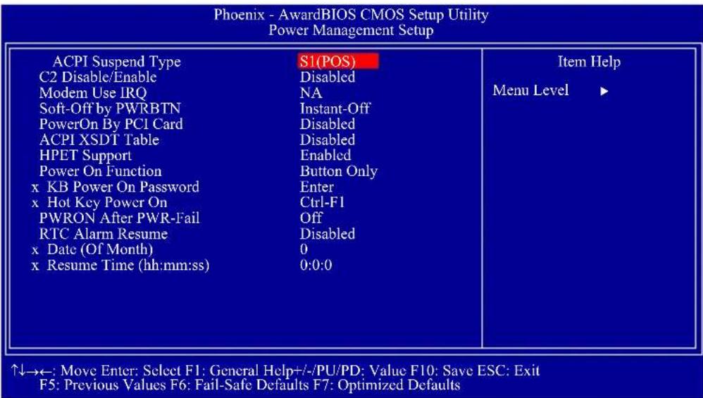
The settings on the screen are for reference only. Your version may not be identical to this one.
ACPI Suspend Type
This field is used to select the type of Suspend mode.
S1(POS)
Enables the Power On Suspend function.
S3(STR)
Enables the Suspend to RAM function.
C2 Disable/Enable
The options are Enabled and Disabled.
MODEM Use IRQ
This field is used to select an IRQ channel for the modem installed in your system.
Soft-Off by PWRBTN
This field allows you to select the method of powering off your system.
Delay 4 Sec.
Regardless of whether the Power Management function is enabled or disabled, if the power button is pushed and released in less than 4 sec, the system enters the Suspend mode. The purpose of this function is to prevent the system from powering off in case you accidentally "hit" or pushed the power button. Push and release again in less than 4 sec to restore. Pushing the power button for more than 4 seconds will power off the system.
Instant-Off
Pressing and then releasing the power button at once will immediately power off your system.
PowerOn By PCI Card
Enabled
This field should be set to Enabled only if your PCI card such as LAN card or modem card uses the PCI PME (Power Management Event) signal to remotely wake up the system. Access to the LAN card or PCI card will cause the system to wake up. Refer to the card's documentation for more information.
Disabled
The system will not wake up despite access to the PCI card.
ACPI XSDT Table
Enable the ACPI XSDT table only when using a 64-bit mode OS. The table does not support 32-bit mode OS such as Windows 2000 and Windows XP.
HPET Support
The options are Enabled and Disabled.
Power On Function
This field allows you to use the PS/2 keyboard or PS/2 mouse to power-on the system.
Button only
Default setting. Uses the power button to power on the system.
Password
When this option is selected, set the password you would like to use to power-on the system in the "KB Power On Password" field.
Hot Key
When this option is selected, select the function key you would like to use to power-on the system in the "Hot Key Power On" field.
MS Move&Click
When this option is selected, move or click the mouse to power-on the system.
Any Key
Press any key to power-on the system.
Keyboard 98
When this option is selected, press the "wake up" key of the Windows 98 compatible keyboard to power-on the system.
KB Power On Password
Move the cursor to this field and press
The power button will not function once a keyboard password has been set in this field. You must type the correct password to power-on the system. If you forgot the password, power-off the system and remove the battery. Wait for a few seconds and install it back before powering-on the system.
Hot Key Power On
This field is used to select a function key that you would like to use to power-on the system.
PWRON After PWR-Fail
Off
When power returns after an AC power failure, the system's power is off. You must press the Power button to power-on the system.
On
When power returns after an AC power failure, the system will automatically power-on.
RTC Alarm Resume
Enabled
When Enabled, you can set the date and time you would like the Soft Power Down (Soft-Off) PC to power-on in the "Date (of Month)" and "Resume Time" fields. However, if the system is being accessed by incoming calls or the network (Resume On Ring/LAN) prior to the date and time set in these fields, the system will give priority to the incoming calls or network.
Disabled
Disables the automatic power-on function. (default).
Date (of Month)
0
The system will power-on everyday according to the time set in the "Time (hh:mm:ss) Alarm" field.
1-31
Select a date you would like the system to power-on. The system will power-on on the set date, and time set in the "Time (hh:mm:ss) Alarm" field.
Resume Time (hh:mm:ss)
This is used to set the time you would like the system to power-on. If you want the system to power-on everyday as set in the "Date (of Month)" field, the time set in this field must be later than the time of the RTC set in the Standard CMOS Features submenu.
PnP/PCI Configurations
This section describes configuring the PCI bus system. It covers some very technical items and it is strongly recommended that only experienced users should make any changes to the default settings.
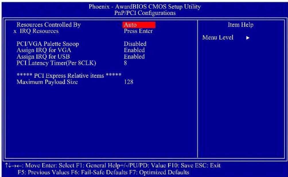
The settings on the screen are for reference only. Your version may not be identical to this one.
Resources Controlled By
The Award Plug and Play BIOS has the capability to automatically configure all of the boot and Plug and Play compatible devices.
Auto(ESCD)
The system will automatically detect the settings for you.
Manual
Choose the specific IRQ in the "IRQ Resources" field.
IRQ Resources
Move the cursor to this field and press
| Phoenix - AwardBIOS CMOS Setup Utility IRQ Resources | ||
| IRQ-3 assigned to IRQ-4 assigned to IRQ-5 assigned to IRQ-7 assigned to IRQ-10 assigned to IRQ-11 assigned to IRQ-12 assigned to IRQ-14 assigned to IRQ-15 assigned to | PCI Device | Item Help Menu Level ▶▶ Legacy ISA for devices compliant with the original PC AT bus specification. PCI/ISA PnP for devices compli- ant with the Plug and Play standard whether designed for PCI or ISA bus architecture. |
| ↑↓→←: Move Enter: Select F1: General Help+/-/PU/PD: Value F10: Save ESC: Exit F5: Previous Values F6: Fail-Safe Defaults F7: Optimized Defaults | ||
The settings on the screen are for reference only. Your version may not be identical to this one.
PCI/VGA Palette Snoop
This field determines whether the MPEG ISA/VESA VGA cards can work with PCI/VGA or not. The default value is Disabled.
Enabled
MPEG ISA/VESA VGA cards work with PCI/VGA.
Disabled
MPEG ISA/VESA VGA cards does not work with PCI/VGA.
Assign IRQ for VGA
When Enabled, the system automatically assigns an IRQ for the VGA card installed. Your VGA card will need an IRQ only when using the video capture function of the card. If you are not using this function and a new device requires an IRQ, you can set this field to Disabled. The IRQ (previously occupied by the VGA card) will be available for your new device.
Assign IRQ for USB
When Enabled, the system automatically assigns an IRQ for the USB device connected to your system. However, if you are not using USB devices and an ISA slot requires an IRQ, set this field to Disabled. The IRQ previously occupied by the USB device will be available for the ISA slot.
PCI Latency Timer (Per 8CLK)
This feature is used to select the length of time each PCI device will control the bus before another takes over. The larger the value, the longer the PCI device can retain control of the bus. Since each access to the bus comes with an initial delay before any transaction can be made, low values for the PCI Latency Timer will reduce the effectiveness of the PCI bandwidth while higher values will improve it.
Maximum Payload Size
This field is used to select the maximum TLP payload size of the PCI Express devices. The unit is byte.
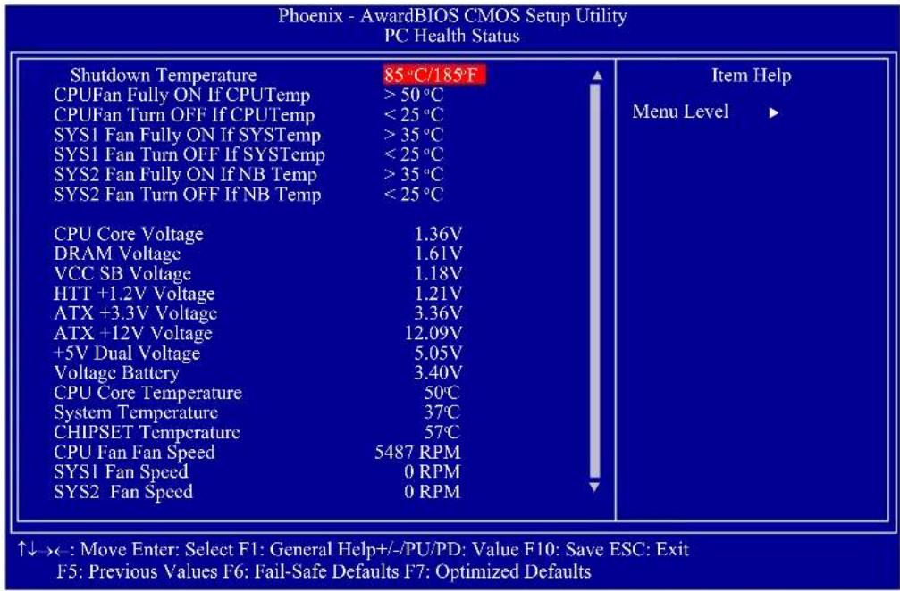
PC Health Status
other
Phoenix - AwardBIOS CMOS Setup Utility PC Health Status | Category | Value | | : | | Item Help | | | | | | | | | | | | | | | | | | | | | | | | | | | | | | | | | | | | | | | | | | | | | | | | | | | / | | | | | | | | | | | | | | | | | | | | | | | | | | | | | | | | | | | | | | | | | | | | | | | | | I C P T e P r o f O F f O F T o F S Y S T o P r S Y S S T o F F U F O F O F N B T o P S Y S S T o F U F O F O F N B T o P S Y S S T o F U F O F O F N BThe screen above list all the fields available in the PC Health Status submenu, for ease of reference in this manual. In the actual CMOS setup, you have to use the scroll bar to view the fields. The settings on the screen are for reference only. Your version may not be identical to this one.
Shutdown Temperature
You can prevent the system from overheating by selecting a temperature at which the system will shutdown. If the system detected that its temperature exceeded the one set in this field, it will automatically shutdown.
CPUFan Fully On If CPUTemp
This field is used to select the CPU's temperature at which the CPU fan will rotate at full speed.
CPUFan Turn Off If CPUTemp
This field is used to select the CPU's temperature at which the CPU fan will rotate at a start speed which is the slowest speed.

Note:
-
If the CPU temperature runs between the highest (set in the "CPUFan Fully On If CPUTemp" field) and lowest (set in the "CPUFan Turn Off If CPUTemp" field) temperature, the system will automatically adjust the CPU fan's speed according to the temperature.
-
If you want to reduce the CPU fan's noise or prevent CPU overheat, select a lower temperature in the "CPUFan Fully On If CPUTemp" field to allow the CPU fan to rotate full speed at the selected lower temperature.
SYS1 Fan Fully On If SYSTemp
This field is used to select the system's temperature at which the chassis fan will rotate at full speed.
SYS1 Fan Turn Off If SYSTemp
This field is used to select the system's temperature at which the chassis fan will rotate at a start speed which is the slowest speed.

Note:
If the system's temperature runs between the highest (set in the "SYS-Fan Fully On If SYSTemp" field) and lowest (set in the "SYSFan Turn Off If SYSTemp" field) temperature, the system will automatically adjust the chassis fan's speed according to the temperature.
SYS2 Fan Fully On If NB Temp
This field is used to select the Northbridge chip's temperature at which the chip's fan will rotate at full speed.
SYS2 Fan Turn Off If NB Temp
This field is used to select the Northbridge chip's temperature at which the chip's fan will rotate at a start speed which is the slowest speed.

Note:
If the Northbridge chip's temperature runs between the highest (set in the "NB Fan Fully On If NB Temp" field) and lowest (set in the "NB Fan Turn Off If NB Temp" field) temperature, the system will automatically adjust the fan speed of the Northbridge chip according to the temperature.
CPU Core Voltage to SYS2 Fan Speed
These fields will show the output voltage, temperature and fan speed of the monitored devices or components.
Genie BIOS Setting
Aimed to provide convenience and superb overclockability, this submenu comes available in Easy mode (default mode) and Advance mode.
Easy Mode
Easy mode displays fields commonly used by users.
Advance Mode
If you intend to tweak your PC or boost its overclock features, you can switch the Genie BIOS Setting submenu from Easy mode to Advance mode by simply pressing
Phoenix - AwardBIOS CMOS Setup Utility Genie BIOS Setting
| DRAM Configuration HT Link Control CPU Feature Memory Current Value Timing Mode x Memory Clock Value or Limit AMD K8 Cool&Quiet Control x CPU-NB Voltage CPU Clock Ratio CPU NB Clock Ratio HT Link Frequency CPU VID Special Add DRAM Voltage Control NB HT Voltage NB Core Voltage NB PCIE Voltage SB PLL 1.2V Voltage Side Port Voltage O.C Fail Retry Counter O.C. Fail CMOS Reload Spread Spectrum CPU Host/HTT Clock CPU Host/HTT Adjust Gap PCIE Clock | Press Enter Press Enter Press Enter DDR1333 Auto DDR3 800 Auto Auto Auto Auto Auto Auto 1.612 V 1.20 V 1.20 V 1.10 V 1.20 V 1.60 V 1 Disabled Disabled 200MHz 5MHz 100MHz |
| CPU Core Voltage | 1.36V |
| DRAM Voltage | 1.61V |
| HTT +1.2V Voltage | 1.21V |
| VCC SB Voltage | 1.18V |
↑↓→←: Move Enter: Select F1: General Help+/-/PU/PD: Value F10: Save ESC: Exit F5: Previous Values F6: Fail-Safe Defaults F7: Optimized Defaults
The screen above list all the fields available in the Genie BIOS Setting submenu, for ease of reference in this manual. In the actual CMOS setup, you have to use the scroll bar to view the fields. The settings on the screen are for reference only. Your version may not be identical to this one.
DRAM Configuration
HT Link Control
CPU Feature
Refer to the following pages for more information on these submenus.
Memory Current Value
This field will show the current value of the system memory.
Timing Mode
Auto
The BIOS will automatically detect all DRAM timing.
MaxMemClk
This option uses the maximum DRAM clock.
Manual
This option allows you to manually select the DRAM's clock speed.
Memory Clock Value or Limit
This is used to select the clock speed of the DIMM.
AMD K8 Cool&Quiet Control
Auto
Enables AMD's Cool'n'Quiet technology. This function allows the system to detect the CPU's tasks and utilization status. When the CPU's task slows down, the system effectively lowers power consumption by changing its CPU speed and voltage, subsequently decreasing its noise level.
Disabled
Disables AMD's Cool'n'Quiet technology.
CPU-NB Voltage
This field allows you to manually adjust to a higher core voltage that is supplied to the Northbridge. If you want to use the Northbridge's default core voltage, leave this field in its default setting.
CPU Clock Ratio
This field is used to select the CPU's frequency ratio.
CPU NB Clock Ratio
This field is used to select the NB's frequency ratio.
HT Link Frequency
The options are Auto, 200MHz, 400MHz, 600MHz, 800MHz and 1 GHz.
CPU VID Special Add
This is used to select the voltage supplied to the CPU.
DRAM Voltage Control
This is used to select the voltage supplied to the DRAM.
NB HT Voltage
This is used to select the Northbridge's HyperTransport voltage.
NB Core Voltage
This is used to select the Northbridge's core voltage.
NB PCIE Voltage
The options are 1.10V to 1.40V.
SB PLL 1.2V Voltage
This field allows you to manually select the Southbridge's core voltage.
Side Port Voltage
This is used to select the SidePort's voltage.
O.C. Fail Retry Counter
The options are 0, 1, 2 and 3.
O.C. Fail CMOS Reload
The options are Disabled, Bank 1, Bank 2, Bank 3 and Bank 4.
Spread Spectrum
Leave this field in its default setting. Do not alter this setting unless advised by an engineer or technician.
CPU Host/HTT Clock
This field is used to enter a CPU Host/HTT Clock value. The minimum is 200 and the maximum is 700.
CPU Host/HTT Adjust Gap
This field is used to enter a CPU Host/HTT adjust gap value.
PCIE Clock
This field is used to enter the PCIE clock. The minimum is 100 and the maximum is 250.
CPU Core Voltage
This field will show the CPU's current voltage.
DRAM Voltage
This field will show the DRAM's current voltage.
HTT +1.2V Voltage
This field will show the HTT's current voltage.
VCC SB Voltage
This field will show the Southbridge's current voltage.
DRAM Configuration
Move the cursor to this field and press
![Phoenix - AwardBIOS CMOS Setup Utility DRAM Configuration ► MCT Memory Timing ► ODC Control Mode DCTs Mode CKE Base Power Down Mode CKE Based Power Down Memory Hole Remapping Auto Optimize Bottom IO x Bottom of [31:24] IO Space Bottom of UMA DRAM [31:24] Press Enter Press Enter Unganged Enabled Per Channel Enabled Enabled C0 FC Item Help Menu Level ► ↑↓: Move PU/PD/+/:- Change Priority F10: Save ESC: Exit F5: Previous Values F6: Fail-Safe Defaults F7: Optimized Defaults](/content/2026/05/1067620/images/3eb02c7497f2f879609654be562bdffd6bd7fc77a130f52d24a092793ac489f4.jpg)
The settings on the screen are for reference only. Your version may not be identical to this one.
MCT Memory Timing ODC Control Mode
Refer to the following pages for more information on these submenus.
DCTs Mode
The options are Ganged and Unganged.
CKE Base Power Down Mode
The options are Enabled and Disabled.
CKE Based Power Down
The options are Per Channel and Per CS.
Memory Hole Remapping
The options are Enabled and Disabled.
Auto Optimize Bottom IO
The options are Enabled and Disabled.
Bottom of [31:24] IO Space
This field is used to enter the memory that will be remapped to another address. The minimum is 0000 and the maximum is 00FF.
Bottom of UMA DRAM [31:24]
This field is used to enter the UMA DRAM value. The minimum is 0000 and the maximum is 00FC.
MCT Memory Timing
Move the cursor to this field and press
| Phoenix - AwardBIOS CMOS Setup Utility MCT Memory Timing | |||
| MCT Memory Timing | Auto | Enabled | Item Help |
| x 2T Mode | Auto | 4 CLK | Menu Level ▶▶ |
| x CAS Latency Time | Auto | 18 CLK | |
| x Precharge Delay (tRAS) | Auto | 5 CLK | |
| x DRAM RAS# Precharge | Auto | 5 CLK | |
| x DRAM RAS# to CAS# Delay | Auto | 3 CLK | |
| x Bank to Bank Cmd (TRRD) | Auto | 24 CLK | |
| x TRC | Auto | 3 CLK | |
| x TRTP | Auto | 6 CLK | |
| x Write Recovery (TWR) | Auto | 3 CLK | |
| x Write-Read Command (TWTR) | Auto | 105 ns | |
| x TRFC0 | Auto | 105 nS | |
| x TRFC1 | Auto | 105 nS | |
| x TRFC2 | Auto | 75 nS | |
| x TRFC3 | Auto | 75 nS | |
| x Trdrd | Auto | 3 CLK | |
| x TrwtT0 | Auto | 5 CLK | |
| x Twrrd | Auto | 0 CLK | |
| x Twrwr | Auto | 3 CLK | |
The settings on the screen are for reference only. Your version may not be identical to this one.
MCT Memory Timing
Auto
The BIOS will automatically detect all the MCT memory timing.
Manual
This option allows you to manually configure the MCT memory timing on the following fields.
2T Mode
This field is used to configure the 2T mode.
CAS Latency Time
This field is used to select the clock cycles for the CAS latency.
Precharge Delay (tRAS)
The options are Auto, 5 CLK to 18 CLK.
DRAM RAS# Precharge
This field is used to select the idle clocks after issuing a precharge command to the DRAM.
DRAM RAS# to CAS# Delay
This field is used to select the latency between the DRAM active command and the read/write command. The options are 2 and 3.
Bank to Bank Cmd (TRRD)
The options are Auto, 2 CLK to 5 CLK.
TRC
Row-Cycle delay. Set the "System Performance" field to Optimal if you want to use the delay time recommended by the DIMM manufacturer.
TRTP
The options are Auto, 2CLK - 4CLK and 3CLK - 5CLK.
Write Recovery (TWR)
This field is used to select the write recovery time when the DRAM safely registers the last write data. This is the time from the last write data to pre-charge.
Write-Read Command (TWTR)
The options are Auto, 1 CLK, 2 CLK and 3 CLK.
TRFC 0 to TRFC 3
These fields are used to select the auto refresh cycle time.
Trdrd
The options are Auto, 2 CLK, 3 CLK, 4 CLK and 5 CLK.
TrwtT0
The options are Auto, 3 CLK to 9 CLK.
Twrrd
The options are Auto, 0 CLK, 1 CLK, 2 CLK and 3 CLK.
Twrwr
The options are Auto, 1 CLK, 2 CLK and 3 CLK.
ODC Control Mode
Move the cursor to this field and press
| Output Driver Comp. Channel A x CPU On-die Termination x DQS Drive Strength x Data Drive Strength x MEMCLK Drive Strength x Addr/Cmd Drive Strength x CS/ODT Drive Strength x CKE Drive Strength Channel B x CPU On-die Termination x DQS Drive Strength x Data Drive Strength x MEMCLK Drive Strength x Addr/Cmd Drive Strength x CS/ODT Drive Strength x CKE Drive Strength | Auto | Item Help Menu Level ▶▶ |
| ↑↓: Move PU/PD/+/−: Change Priority F10: Save ESC: Exit F5: Previous Values F6: Fail-Safe Defaults F7: Optimized Defaults | ||
The settings on the screen are for reference only. Your version may not be identical to this one.
Output Driver Comp.
The options are Auto and Manual.
CPU On-die Termination
The options are 300 ohms +/-20%, 150 ohms +/-20% and 75 ohms +/-20%.
DQS Drive Strength
The options are 0.75x, 1.00x, 1.25x and 1.50x.
Data Drive Strength
The options are 0.75x, 1.00x, 1.25x and 1.50x.
MEMCLK Drive Strength
The options are 0.75x, 1.00x, 1.25x and 1.50x.
Addr/Cmd Drive Strength
The options are 1.00x, 1.25x, 1.50x and 2.00x.
CS/ODT Drive Strength
The options are 1.00x, 1.25x, 1.50x and 2.00x.
CKE Drive Strength
The options are 1.00x, 1.25x, 1.50x and 2.00x.
HT Link Control
Move the cursor to this field and press
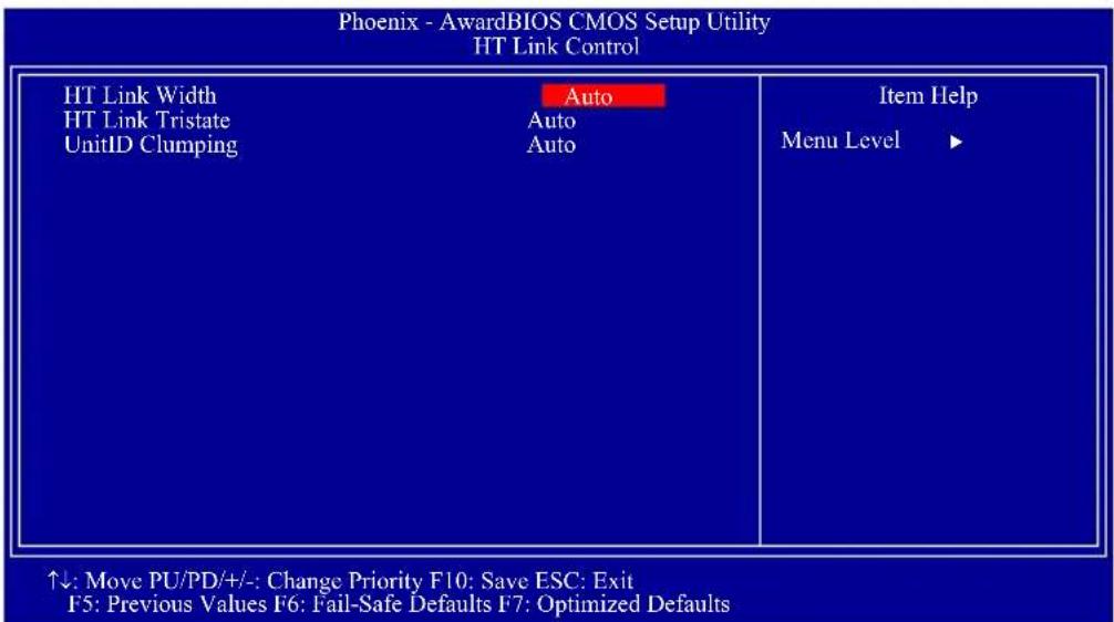
The settings on the screen are for reference only. Your version may not be identical to this one.
HT Link Width
The options are Auto, 8 bit and 16 bit.
HT Link Tristate
The options are Auto, Disabled, CAD/CTL and CAD/CTL/CLK.
UnitID Clumping
The options are Auto, Disabled, PCIE, GFX and PCIE & GFX.
CPU Feature
Move the cursor to this field and press
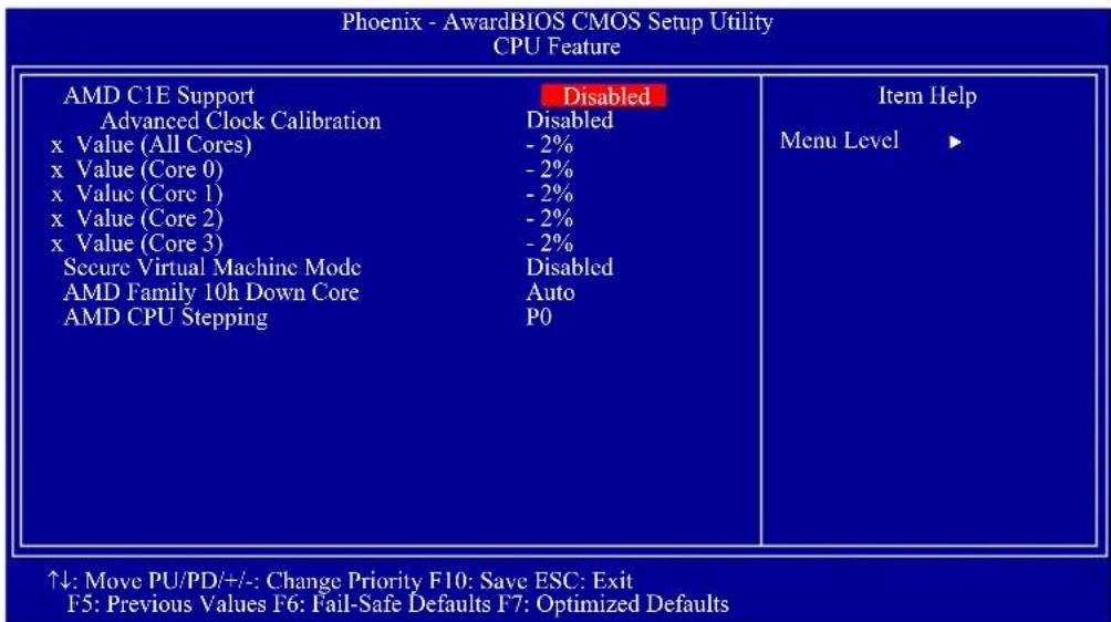
The settings on the screen are for reference only. Your version may not be identical to this one.
AMD C1E Support
The options are Disabled and SoftWare SMI.
Advanced Clock Calibration
This field is used to configure the advanced clock calibration. The options are Disabled, Auto, All Cores and Per Core.
Value (All Cores) to Value (Core 3)
These fields are used to select the core value. The options are 0x to -12x
Secure Virtual Machine Mode
The options are Enabled and Disabled.
AMD Family 10h Down Core
The options are Auto, Single Core, Dual Core, Tri Core and Quad Core.
AMD CPU Stepping
The options are P0, P1, P2 and P3.
CMOS Reloaded
The CMOS Reloaded submenu allows you to save different configurations and when needed, allows you to conveniently restore one of these previously saved configurations. Highlight CMOS Reloaded in the main menu then press
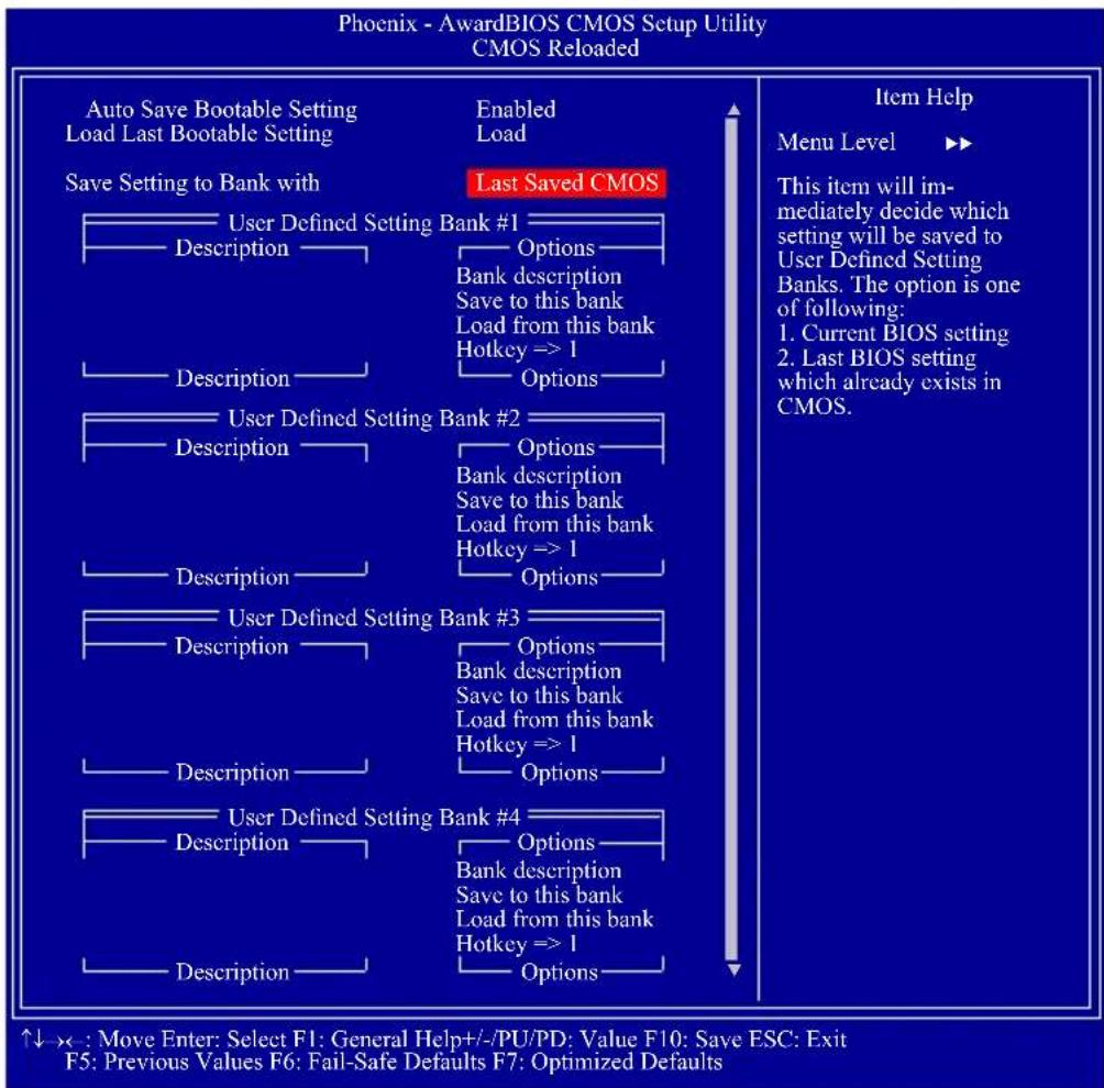
flowchart
graph TD
    A["Save Setting to Bank with"] --> B["Last Saved CMOS"]
    B --> C["User Defined Setting Bank #1 Description"]
    B --> D["User Defined Setting Bank #2 Description"]
    B --> E["User Defined Setting Bank #3 Description"]
    B --> F["User Defined Setting Bank #4 Description"]
    C --> G["Options"]
    D --> H["Options"]
    E --> I["Options"]
    F --> J["Options"]
    style A fill:#f9f,stroke:#333
    style B fill:#ccf,stroke:#333
    style C fill:#cfc,stroke:#333
    style D fill:#cfc,stroke:#333
    style E fill:#cfc,stroke:#333
    style F fill:#cfc,stroke:#333
The screen above list all the fields available in the CMOS Reloaded submenu, for ease of reference in this manual. In the actual CMOS setup, you have to use the scroll bar to view the fields. The settings on the screen are for reference only. Your version may not be identical to this one.
CMOS Reloaded is especially helpful to overclockers who often go through the tiresome trial and error process of repeatedly changing the BIOS settings to come up with the most ideal overclocked setting. By being able to save and load the settings, it eliminates the tedious job of remembering several settings and/or repeatedly resetting settings during the trial process. The settings are stored in the SEEPROM. SEEPROM is divided into 5 banks - the backup bank and the 4 user defined banks.
Auto Save Bootable Setting
This field is used to automatically save the last bootable setting from CMOS to an area in the SEEPROM referred to as the backup bank. To use this function:
- Set this field to Enabled.
- Select "Save & Exit Setup" in the main menu then press
. - Type
then press .
If the changes to the setting allowed the system to boot, the setting will be stored in the SEEPROM. In other words, if the system did not boot up, the setting will not be stored. You may then follow the steps in the next section to load the last bootable setting.
Load Last Bootable Setting
If, during the trial and error process, the setting resulted to the system's instability or worse yet, not being able to boot up the system, please follow the steps below to use the Load function.

Note:
You can use the Load function only if you have set the "Auto Save Bootable Setting" to Enabled.
- If the system did not boot up properly but you were able to enter the BIOS utility:
a. Select "CMOS Reloaded" in the main menu then press
b. Move the cursor to "Load Last Bootable Setting" then press "Load".
c. Press
- If you cannot enter the BIOS utility:
a. Use the Clear CMOS jumper to clear the CMOS. Refer to chapter 2 for more information about clearing CMOS.
b. Enter the BIOS utility then perform steps 1a to 1c.
Saving, Loading and Naming BIOS Settings
For overclockers who require different sets of settings for various system environments or operating systems, CMOS Reloaded allows you to save, load and name up to four sets of BIOS settings - in the "User Defined Setting Bank #1" to "User Defined Setting Bank #4" fields.
Save Setting to Bank With
This field is used to select the type of setting you would like saved to a User Defined Setting Bank when you use the "Save to this Bank" function of that bank.
Current BIOS Setting
This option will save the current BIOS setting to the User Defined Setting Bank.
Last BIOS Setting
This option will save the last saved BIOS setting to the User Defined Setting Bank.
User Defined Setting Bank #1/2/3/4
Bank Description
To name the BIOS setting, move the cursor to "Bank Description" then press
Save to this Bank
To save the BIOS setting, move the cursor to "Save to this Bank" then press
Load from this Bank
To load the setting saved in the bank, move the cursor to "Load from this Bank" then press
Hotkey
You can now load a BIOS setting during system boot up; bypassing the lengthy process of entering the BIOS utility to load a setting. Move the cursor to "Hotkey" then press
Load Optimized Defaults
The "Load Optimized Defaults" option loads optimized settings from the BIOS ROM. Use the default values as standard values for your system. Highlight this option in the main menu and press
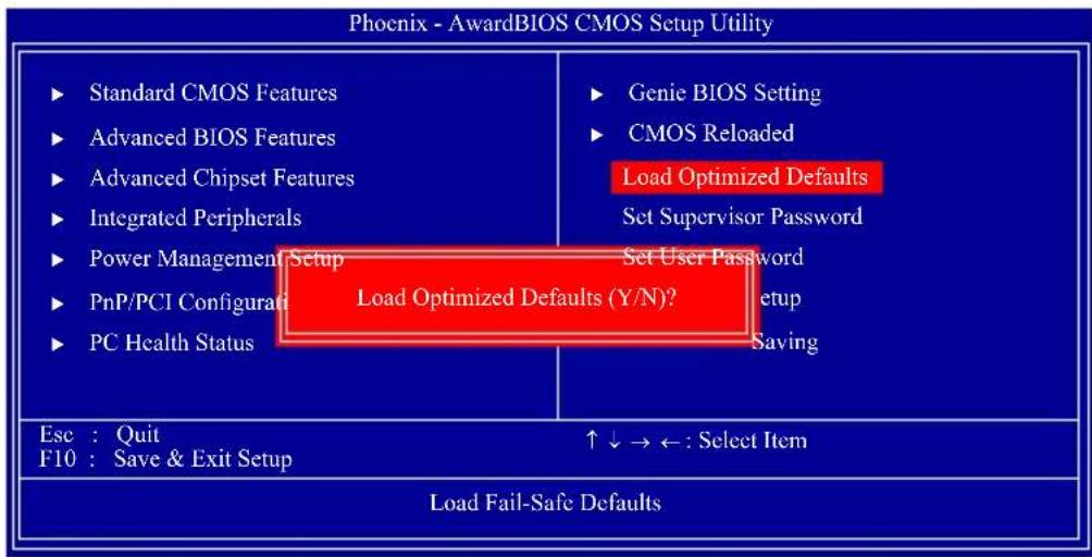
flowchart
graph TD
    A["Standard CMOS Features"] --> B["Advanced BIOS Features"]
    B --> C["Advanced Chipset Features"]
    C --> D["Integrated Peripherals"]
    D --> E["Power Management Setup"]
    E --> F["PnP/PCI Configurals"]
    F --> G["PC Health Status"]
    H["Genie BIOS Setting"] --> I["CMOS Reloaded"]
    I --> J["Load Optimized Defaults"]
    J --> K["Set Supervisor Password"]
    J --> L["Set User Password"]
    J --> M["Setup"]
    J --> N["Saving"]
    O["Load Fail-Safe Defaults"] --> P["Esc : Quit"]
    P --> Q["F10 : Save & Exit Setup"]
    Q --> R["↑↓→←: Select Item"]
    style A fill:#f9f,stroke:#333
    style H fill:#f9f,stroke:#333
    style O fill:#f9f,stroke:#333
Type
Set Supervisor Password
If you want to protect your system and setup from unauthorized entry, set a supervisor's password with the "System" option selected in the Advanced BIOS Features. If you want to protect access to setup only, but not your system, set a supervisor's password with the "Setup" option selected in the Advanced BIOS Features. You will not be prompted for a password when you cold boot the system.
Use the arrow keys to highlight "Set Supervisor Password" and press
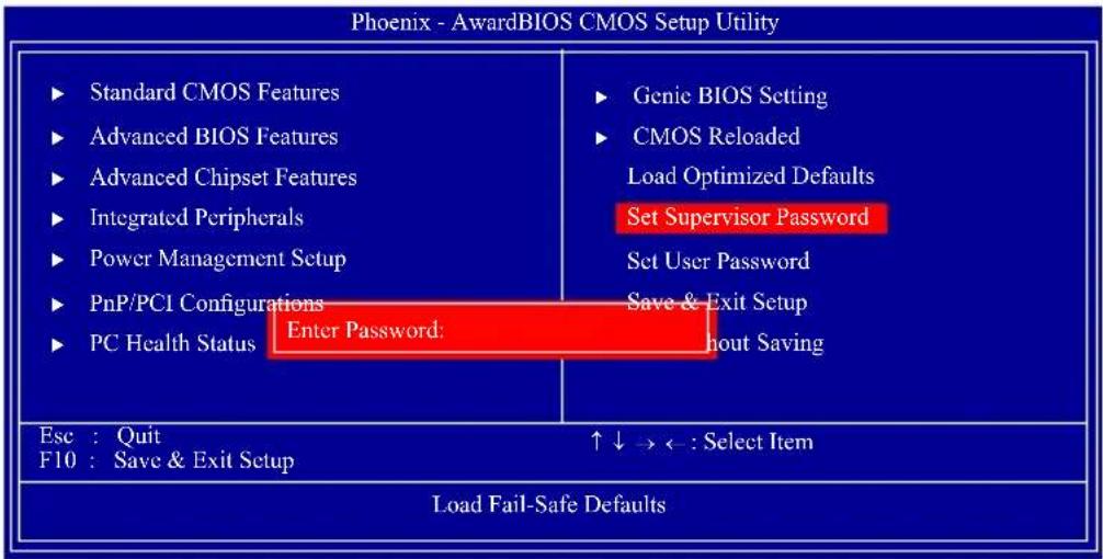
Type in the password. You are limited to eight characters. When done, the message below will appear:
Confirm Password:
You are asked to verify the password. Type in exactly the same password. If you type in a wrong password, you will be prompted to enter the correct password again. To delete or disable the password function, highlight "Set Supervisor Password" and press
Set User Password
If you want another user to have access only to your system but not to setup, set a user's password with the "System" option selected in the Advanced BIOS Features. If you want a user to enter a password when trying to access setup, set a user's password with the "Setup" option selected in the Advanced BIOS Features.
Using user's password to enter Setup allows a user to access only "Set User Password" that appears in the main menu screen. Access to all other options is denied.
Use the arrow keys to highlight "Set User Password" and press
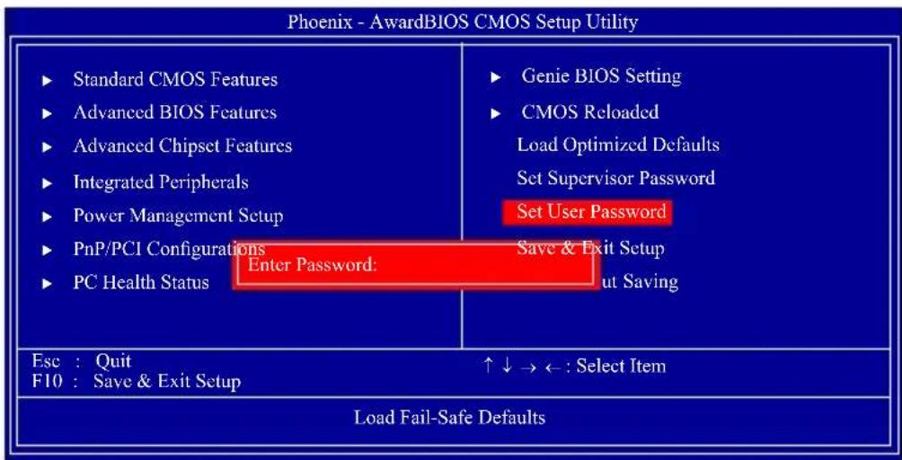
Type in the password. You are limited to eight characters. When done, the message below will appear:
Confirm Password:
You are asked to verify the password. Type in exactly the same password. If you type in a wrong password, you will be prompted to enter the correct password again. To delete or disable the password function, highlight "Set User Password" and press
Save & Exit Setup
When all the changes have been made, highlight "Save & Exit Setup" and press
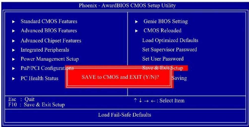
flowchart
graph TD
    A["Standard CMOS Features"] --> B["Advanced BIOS Features"]
    B --> C["Advanced Chipset Features"]
    C --> D["Integrated Peripherals"]
    D --> E["Power Management Setup"]
    E --> F["PnP/PCI Configurations"]
    F --> G["PC Health Status"]
    H["Genie BIOS Setting"] --> I["CMOS Reloaded"]
    I --> J["Load Optimized Defaults"]
    J --> K["Set Supervisor Password"]
    K --> L["Set User Password"]
    L --> M["Save & Exit Setup"]
    M --> N["SAVE to CMOS and EXIT (Y/N)?"]
    O["Esc : Quit"] --> P["F10 : Save & Exit Setup"]
    Q["↑↓→←: Select Item"] --> R["Load Fail-Safe Defaults"]
Type "Y" and press after memory testing is done.
Exit Without Saving
When you do not want to save the changes you have made, highlight "Exit Without Saving" and press
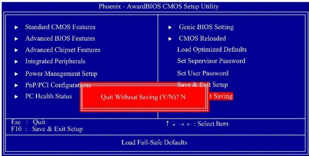
flowchart
graph TD
    A["Standard CMOS Features"] --> B["Advanced BIOS Features"]
    B --> C["Advanced Chipset Features"]
    C --> D["Integrated Peripherals"]
    D --> E["Power Management Setup"]
    E --> F["PnP/PCI Configurations"]
    F --> G["PC Health Status"]
    H["Genie BIOS Setting"] --> I["CMOS Reloaded"]
    I --> J["Load Optimized Defaults"]
    J --> K["Set Supervisor Password"]
    K --> L["Set User Password"]
    L --> M["Save & Exit Setup"]
    M --> N["Quit Without Saving (Y/N)? N"]
    O["Esc : Quit"] --> P["F10 : Save & Exit Setup"]
    Q["↑↓→←: Select Item"] --> R["Load Fail-Safe Defaults"]
Type "Y" and press after memory testing is done.
RAID BIOS
The AMD BIOS utility is used to configure and manage RAID on Serial ATA drives.
After you power up the system and all drives have been detected, the AMD BIOS status message screen will appear. Press the

Important:
Before creating RAID, make sure you have installed the Serial ATA drives and connected the data cables otherwise you won't be able to enter the RAID BIOS utility.
Refer to chapter 5 for steps in configuring RAID.
Updating the BIOS
To update the BIOS, you will need the new BIOS file and a flash utility, AWD-FLASH.EXE. You can download them from DFI's web site or contact technical support or your sales representative.
- Save the new BIOS file along with the flash utility AWDFLASH.EXE to a floppy disk.
- Reboot the system and enter the Award BIOS Setup Utility to set the first boot drive to "Floppy".
- Save the setting and reboot the system.
- After the system booted from the floppy disk, execute the flash utility by typing AWDFLASH.EXE. The following screen will appear.
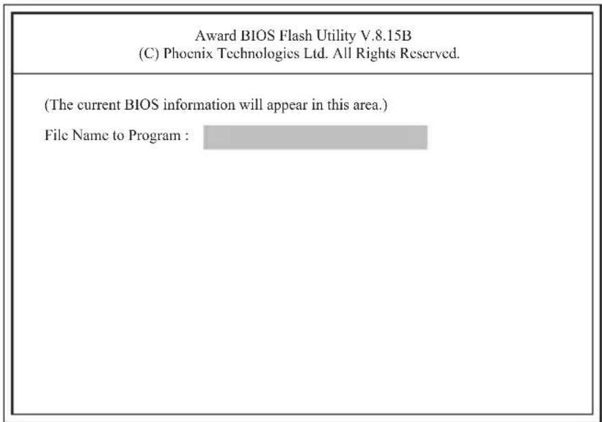
-
Type the new BIOS file name onto the gray area that is next to "File Name to Program" then press
. -
The following will appear.
Do You Want to Save BIOS (Y/N)
This question refers to the current existing BIOS in your system. We recommend that you save the current BIOS and its flash utility; just in case you need to reinstall the BIOS. To save the current BIOS, press
- The following will then appear.
Press "Y" to Program or "N" to Exit
- Press
to flash the new BIOS.
Chapter 4 - Supported Software
The DVD that came with the system board contains drivers, utilities and software applications required to enhance the performance of the system board.
Insert the DVD into an optical drive. The screen shown below will appear. If after inserting the DVD, "Autorun" did not automatically start, please go directly to the root directory of the DVD and double-click "Setup".

AMD RS880 Drivers
On the top row of the screen, click the 1st icon to open the Chipset Driver menu.
- Click "AMD RS880 Drivers".

- Select the components you want to install then click Next.
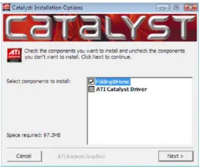
- Click Install to install to the destination folder or click Browse to select another folder.
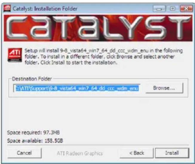
- The installation program is extracting the files needed to install the driver.
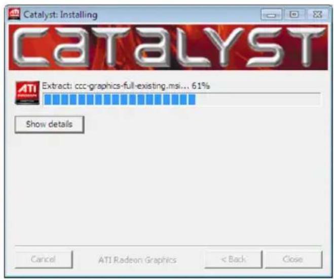
- Select the language for this installation then click Next.
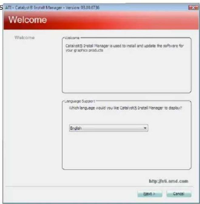
- The installation program is now ready to install the driver. Click Install.
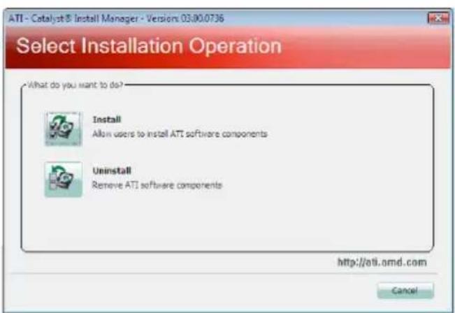
- Select the component (Express or Custom) you want to install then click Next.
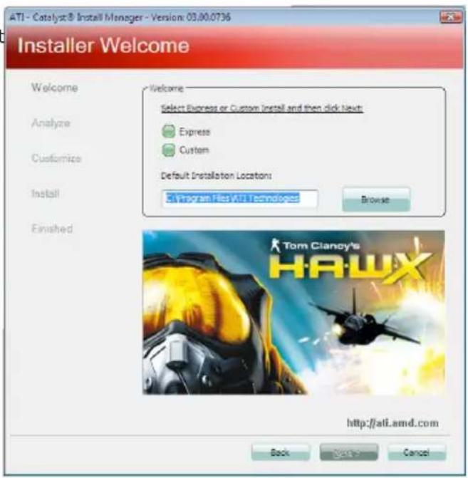
- Read the license agreement then click Accept.
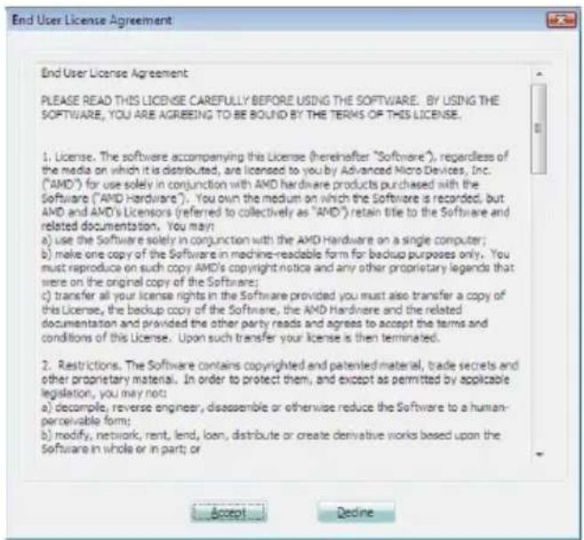
- The Catalyst Install Manager is now installing the driver.
- The driver has been completely installed. Click Finish.
- Click Yes to reboot the system.
Restarting the system will allow the new driver installation to take effect.
AMD South Bridge Drivers
On the top row of the screen, click the 1st icon to open the Chipset Driver menu.
- Click "AMD South Bridge Drivers".

- Click Install to install to the destination folder or click Browse to select another folder.
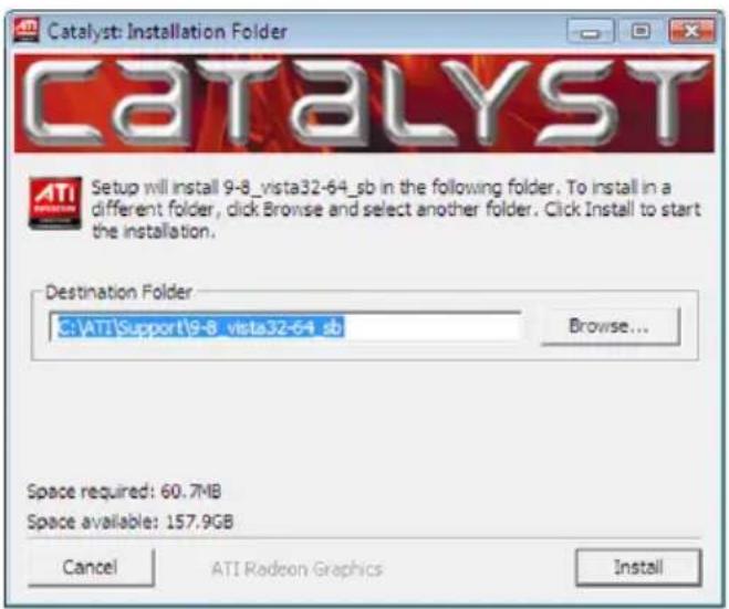
- Select the language for this installation then click OK.

- The installation program is extracting the files needed to install the driver.
- The installation program is now ready to install the driver. Click Next.
- Read the license agreement then click "I accept the terms in the license agreement". Click Next.
- Click Next to install to the destination folder or click Browse to select another folder.
- Click Next.
- Click Install to begin the installation.
- The driver has been completely installed. Click Finish.
WebPAM Utility
On the top row of the screen, click the 1st icon to open the Chipset Driver menu.
- Click "WebPAM Utility".

- The installation program is now ready to install the utility. Click Next.
- Read the license agreement then click "I accept the terms of the license agreement". Click Next.
- Click Next to install to the destination folder or click Browse to select another folder.
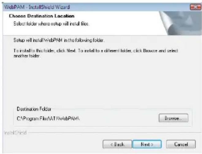
- Click Install to begin the installation.
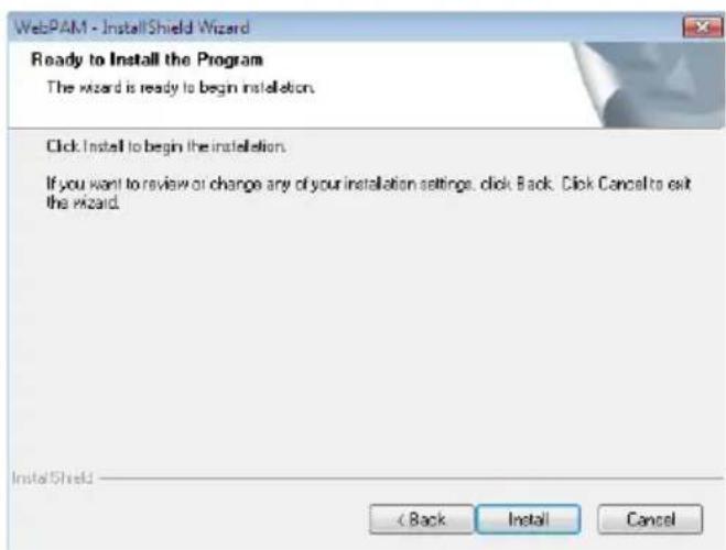
- The utility has been completely installed. Click Finish.
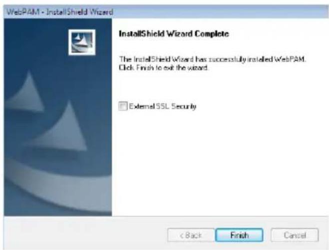
- The first time you run the WebPam utility, the default Login ID and password is admin. You can later change the ID and password after you have entered the utility.
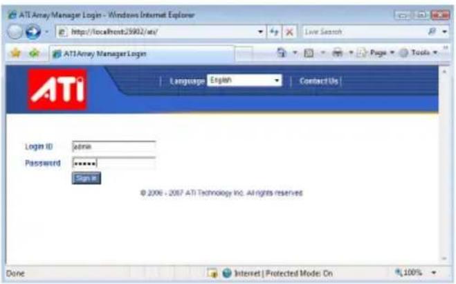
ATi Radeon Drivers
On the top row of the screen, click the 2nd icon to open the Graphics Driver menu.
- Click "ATi Radeon Drivers".

- Select the components you want to install then click Next.
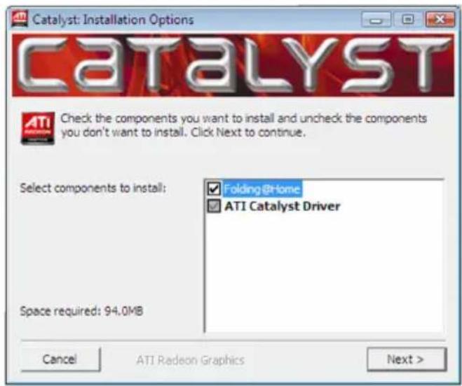
- Click Install to install to the destination folder or click Browse to select another folder.
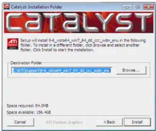
- The installation program is extracting the files needed to install the driver.
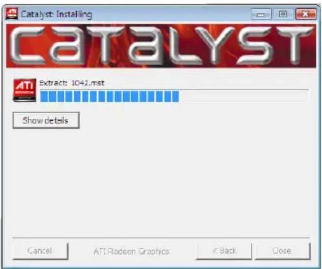
- Select the language for this installation then click Next.
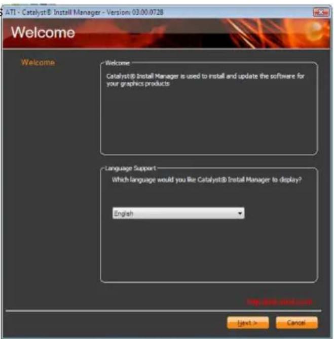
- The installation program is now ready to install the driver. Click Install.
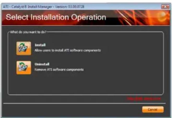
- Select the component (Express or Custom) you want to install then click Next.
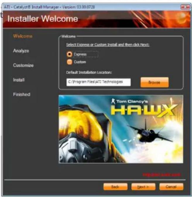
- Read the license agreement then click Accept.

- The Catalyst Install Manager is now installing the driver.
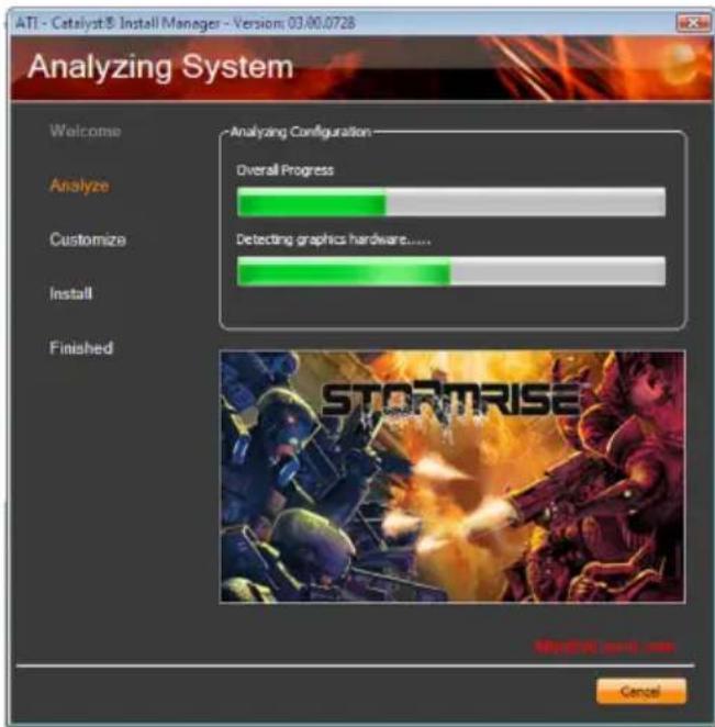
- Click Yes to reboot the system.
Rebooting the system will allow the new driver installation to take effect.
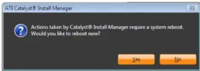
nVidia GForce 8 Series Drivers
On the top row of the screen, click the 2nd icon to open the Graphics Driver menu.
- Click "n V idia G For ce 8 Series Drivers".

- Click Next to install to the destination folder or click Change to select another folder.
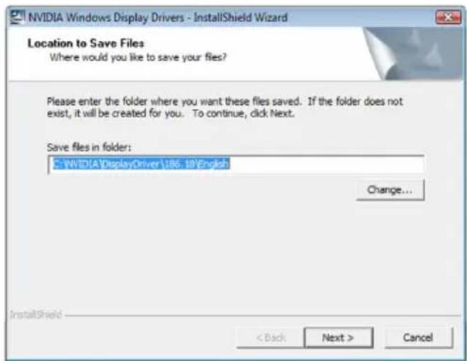
- The installation program is extracting the files needed to install the driver.
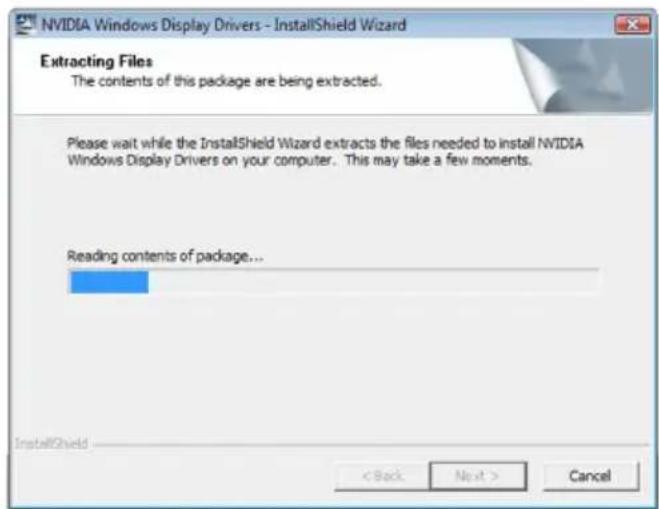
- Click Next to begin the installation.
- Read the license agreement then click Yes.
- Click Finish.
Realtek Audio Drivers
On the top row of the screen, click the 3rd icon to open the Audio Driver menu.
- Click "Realtek Audio Drivers".

- Setup is preparing the installation program which will guide you through the installation process.
- Click Next to begin the installation.
- The installation program is currently installing the driver.
- Click "Yes, I want to restart my computer now" then click Finish.
Restarting the system will allow the new driver installation to take effect.
JMC250 LAN Drivers
On the top row of the screen, click the 4th icon to open the Network Driver menu.
- Click "JMC250 LAN Drivers".

- Click Install to begin the installation.
- The installation program is now installing the driver.
- Click Finish.
- Reboot the system for the driver to take effect.
RAID Floppy Driver
On the top row of the screen, click the 5th icon to open the RAID Driver menu.
- Click "RAID Floppy Driver".

- Windows Explorer will appear showing the folder where the driver files are located in the DVD.
- You must create a RAID driver floppy diskette which is needed when you install the RAID driver during Windows installation.
Run the appropriate execution file.
- Insert a blank floppy diskette then click OK.
- The system will format and write the necessary driver files into the diskette.
Smart Guardian
The Smart Guardian utility is capable of monitoring the system's temperature, fan speed, voltage, etc. and allows you to manually set a range (Highest and Lowest Limit) to the items being monitored. If the settings/values are over or under the set range, a warning message will pop-up. The utility can also be configured so that a beeping alarm will sound whenever an error occurs. We recommend that you use the "Default Setting" which is the ideal setting that would keep the system in good working condition.
On the top row of the screen, click the 6th icon to open the Utility menu.
- Click "Smart Guardian".

- The installation program is extracting the files needed to install the utility.
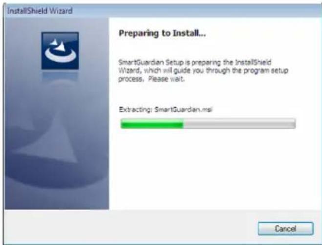
- The installation program is now ready to install the utility. Click Next.
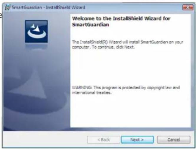
- Click Next to install to the designated folder or click Change to select another folder.
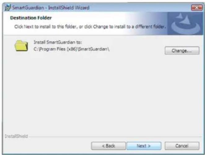
- Click Install to begin installation.

- The installation program is currently installing the utility.
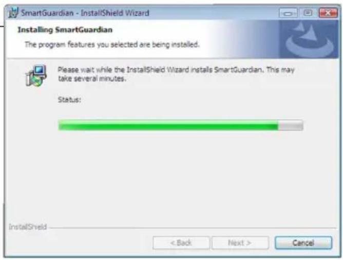
- Click Finish. Reboot the system for the driver to take effect.

- After rebooting the system, you will find the Smart Guardian icon displayed on the screen. Double-click the icon to run the utility.
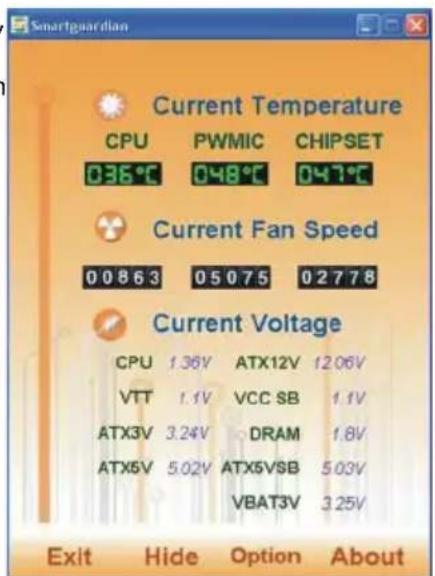
AMD OverDrive
On the top row of the screen, click the 6th icon to open the Utility menu.
- Click "AMD OverDrive".

- The installation program is extracting the files needed to install the utility.
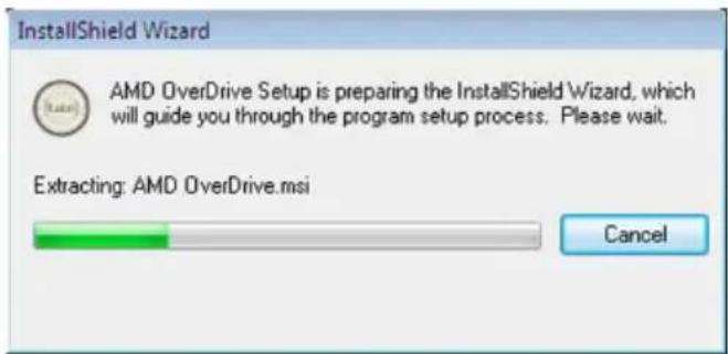
- The installation program is now ready to install the utility. Click Next.
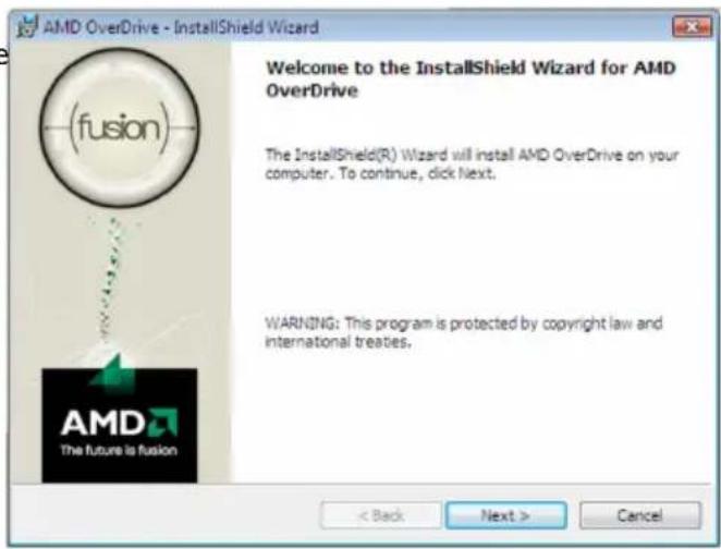
- Read the license agreement. Click "I accept the terms in the license agreement" then click Next.

- Go through the readme document for system requirements and installation tips then click Next.
- Fill in the necessary information then click Next.
- Click Next to install to the designated folder or click Change to select another folder.
- Click Yes if you want to create a shortcut on your desktop, then click Next.
- Click Install to begin the installation.
- The installation program is currently installing the utility.
- Click Finish.
Adobe Acrobat Reader 7.05
On the top row of the screen, click the last icon to open the Manuals menu.
- Click "Adobe Acrobat Reader 7.05".
- Click Next to continue.

- Setup is now ready to install. Click Next.
- Click Next to install or click Change Destination Folder to select another folder.
- Click Install to begin installation.
- Click Finish to exit installation.
The AMD SB710 chip allows configuring RAID on Serial ATA drives. It supports RAID 0/1/0+1(10).
RAID Levels
RAID 0 (Striped Disk Array without Fault Tolerance)
RAID 0 uses two new identical hard disk drives to read and write data in parallel, interleaved stacks. Data is divided into stripes and each stripe is written alternately between two disk drives. This improves the I/O performance of the drives at different channel; however it is not fault tolerant. A failed disk will result in data loss in the disk array.
RAID I (Mirroring Disk Array with Fault Tolerance)
RAID 1 copies and maintains an identical image of the data from one drive to the other drive. If a drive fails to function, the disk array management software directs all applications to the other drive since it contains a complete copy of the drive's data. This enhances data protection and increases fault tolerance to the entire system. Use two new drives or an existing drive and a new drive but the size of the new drive must be the same or larger than the existing drive.
RAID 0+1 (Striping and Mirroring)
RAID 0+1 is a combination of data striping and data mirroring providing the benefits of both RAID 0 and RAID 1. Use four new drives or an existing drive and three new drives for this configuration.
Settings
To enable the RAID function, the following settings are required.
- Connect the Serial ATA drives.
- Configure Serial ATA in the Award BIOS.
- Configure RAID in the RAID BIOS.
- Install the RAID driver during OS installation.
Step I: Connect the Serial ATA Drives
Refer to chapter 2 for details on connecting the Serial ATA drives.

Important:
-
Make sure you have installed the Serial ATA drives and connected the data cables otherwise you won't be able to enter the RAID BIOS utility.
-
Treat the cables with extreme caution especially while creating RAID. A damaged cable will ruin the entire installation process and operating system. The system will not boot and you will lost all data in the hard drives. Please give special attention to this warning because there is no way of recovering back the data.
Step 2: Configure Serial ATA in the Award BIOS
- Power-on the system then press
to enter the main menu of the Award BIOS. - Configure Serial ATA in the appropriate fields.
- Press
to return to the main menu of the BIOS setup utility. Select "Save & Exit Setup" then press . - Type
and press . - Reboot the system.
Step 3: Configure RAID in the RAID BIOS
When the system powers-up and all drives have been detected, the AMD BIOS status message screen will appear. Press the
Step 4: Install the RAID Driver During OS Installation
The RAID driver must be installed during the Windows® XP installation using the F6 installation method. This is required in order to install the operating system onto a hard drive or RAID volume when in RAID mode or onto a hard drive when in AHCI mode.
- Start Windows Setup by booting from the installation CD.
- Press
when prompted in the status line with the 'Press F6 if you need to install a third party SCSI or RAID driver' message. - Press
to "Specify Additional Device". - At this point you will be prompted to insert a floppy disk containing the RAID driver. Insert the RAID driver diskette.
5
RAID
- Locate for the drive where you inserted the diskette then select RAID or AHCI controller that corresponds to your BIOS setup. Press
to confirm.
You have successfully installed the driver. However you must continue installing the OS. Leave the floppy disk in the floppy drive until the system reboots itself because Windows setup will need to copy the files again from the floppy disk to the Windows installation folders. After Windows setup has copied these files again, remove the floppy diskette so that Windows setup can reboot as needed.
Based on the ATI CrossFire™ multi-GPU technology, Hybrid Graphics takes gaming experience to the next level. Hybrid Graphics is a combination of the integrated graphics and a discrete graphics card delivering high quality gaming images and improved performance. Its multi-GPU performance capabilities enhance gaming performance, productivity and platform power efficiency to the mainstream PC.
Basic Requirements
- Windows ^® Vista operating system.
- A Hybrid- Graphics-supported discrete graphics card.
- Minimum of 1GB system memory.
- 256MB onboard graphics RAM.
Hybrid Graphics Setup
- Configure the BIOS.
Set the "UMA Frame Buffer Size" field to 256MB.
Set the "Surround View" field to Enabled.
Refer to the "IGX Configuration" section (Advanced Chipset Features submenu of the Award BIOS) in chapter 3 for more information.
- Install the AMD RS880 chipset driver then restart the system for the new driver to take effect.
Refer to the "AMD RS880 Driver" section in chapter 4 for more information. - Install a graphics card. Hybrid Graphics supports only one discrete graphics card to work with the integrated GPU.
- Install the graphics driver. Refer to the "ATI Radeon Driver" section in chapter 4 for more information.
- Run the ATI Catalyst Control Center utility to enable Hybrid Graphics.
Chapter 7 - Cool'n'Quiet Technology
Cool'n'Quiet Technology
The AMD Cool'n'Quiet™ technology allows the system to detect the CPU's tasks and utilization status. When the CPU's task slows down, the system effectively lowers power consumption by lowering its CPU speed and voltage, subsequently decreasing its noise level.
To enable the Cool'n'Quiet™ technology, the following settings are required.
- Install the Cool'n'Quiet ^TM driver.
- Configure Power Management in Windows.
Step 1: Install the Cool'n'Quiet™ Driver
AMD's website provides free download of the Cool'n'Quietdriver. Make sure to install the appropriate driver for the CPU that you are using.
Step 2: Configure Power Management in Windows
- On the Windows desktop, click Start then select Control Panel.
- In Control Panel, double-click the Power Options icon.
- In the Power Schemes tab, select Minimal Power Management under the Power schemes section then click OK.
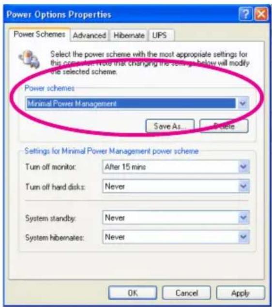
Display Interfaces
The system board is equipped with VGA (D-Sub), DVI-I (DVI-D signal) and HDMI ports.
VGA (D-Sub) Port
The VGA port is a 15-pin D-Sub connector. Connect a monitor that supports D-Sub connection to this port.
DVI-I (DVI-D signal) Port
The DVI-I port supports DVI-D signal only. Connect a digital LCD monitor to this port.

Note:
The DVI-I port does not support a DVI-I-to-VGA adapter (that is used for connecting an analog VGA monitor).
- The system board does not support simultaneous display from DVI-I and HDMI.
HDMI Port
HDMI (High-Definition Multimedia Interface) provides an all-digital audio/video interface to transmit the uncompressed audio/video signals. HDMI is HDCP compliant. Connect an HDMI audio/video device to this port. The HDMI technology can support maximum resolution of 1920x1080p but the actual resolution displayed will depend on the monitor being used.
Jumper Setting
After connecting the HDMI device, set jumpers JP20 and JP21 to HDMI. Refer to the HDMI/DVI Select section in chapter 2 for more information.
Sound Playback
The Sound Playback's default device must be an HDMI device. The HDMI option shown in the Sound Playback dialog box may vary depending on Operating System used.
The HDMI audio output supports AC3, DTS and 2-channel-LPCM formats. AC3 and DTS require the use of an external decoder for decoding.
The screen below was captured from Windows Vista.
- Click Start and then Control Panel.
- Double-click the Sound icon.
- In the Playback tab, select Digital Output Device (HDMI) then click Set Default.
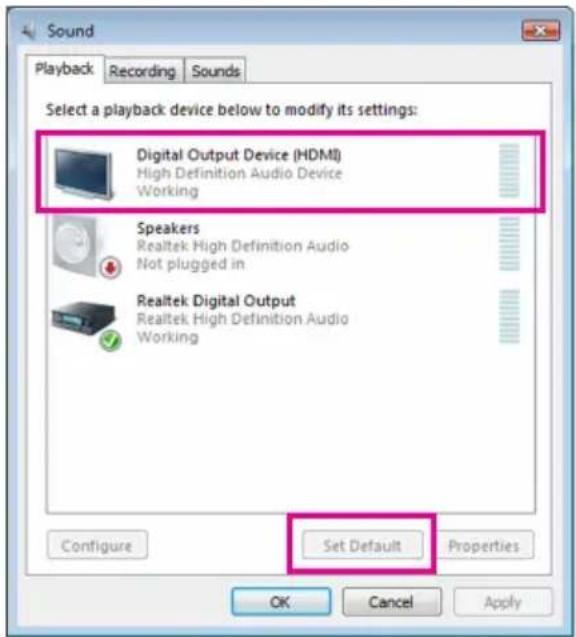
Dual Display Configuration
The table below lists the supported dual display configuration.
| Dual Display | |
| VGA + DVI-I | Supported |
| VGA + HDMI | Supported |
| DVI-I + HDMI | Not Supported |
Playback of HD DVD and Blu-ray Discs
Refer to the recommended (or better) system requirements for better playback quality.
Memory•
Two 1GB DDR3 1066MHz memory modules with dual channel mode enabled.
BIOS Setup•
At least 256MB of UMA Frame Buffer Size (refer to chapter 3 - BIOS Setup Advanced BIOS Features section for more information).
Playback Software•
CyberLink PowerDVD 8.0 or later
Note: Hardware Acceleration must be enabled.
HDCP compliant monitor(s)•
Chapter 9 - Audio Configuration
Configuring 2/4/5.1/7.1-Channel Audio
The 6 audio jacks at the rear panel of the system board support 2/4/5.1/7.1-channel audio. The illustration below shows the default audio jack assignments.
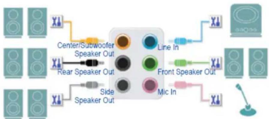
flowchart
graph TD
    A["Speaker 1"] --> B["Center/Subwoofer Speaker Out"]
    C["Speaker 2"] --> B
    D["Speaker 3"] --> E["Rear Speaker Out"]
    F["Speaker 4"] --> G["Side Speaker Out"]
    H["Speaker 5"] --> I["Side Speaker Out"]
    J["Speaker 6"] --> K["Side Speaker Out"]
    L["Speaker 7"] --> M["Side Speaker Out"]
    N["Speaker 8"] --> O["Side Speaker Out"]
    P["Speaker 9"] --> Q["Side Speaker Out"]
    R["Speaker 10"] --> S["Side Speaker Out"]
    T["Speaker 11"] --> U["Side Speaker Out"]
    V["Speaker 12"] --> W["Side Speaker Out"]
    X["Speaker 13"] --> Y["Side Speaker Out"]
    Z["Speaker 14"] --> AA["Side Speaker Out"]
    AB["Speaker 15"] --> AC["Side Speaker Out"]
    AD["Speaker 16"] --> AE["Side Speaker Out"]
    AF["Speaker 17"] --> AG["Side Speaker Out"]
    AH["Speaker 18"] --> AI["Side Speaker Out"]
    AJ["Speaker 19"] --> AK["Side Speaker Out"]
    AL["Speaker 20"] --> AM["Side Speaker Out"]
    AN["Speaker 21"] --> AO["Side Speaker Out"]
    AP["Speaker 22"] --> AQ["Side Speaker Out"]
    AR["Speaker 23"] --> AS["Side Speaker Out"]
    AT["Speaker 24"] --> AU["Side Speaker Out"]
    AV["Speaker 25"] --> AW["Side Speaker Out"]
    AX["Speaker 26"] --> AY["Side Speaker Out"]
    AZ["Speaker 27"] --> BA["Side Speaker Out"]
    BB["Speaker 28"] --> BC["Side Speaker Out"]
    BD["Speaker 29"] --> BE["Side Speaker Out"]
    BF["Speaker 30"] --> BG["Side Speaker Out"]
    BH["Speaker 31"] --> BI["Side Speaker Out"]
    BJ["Speaker 32"] --> BK["Side Speaker Out"]
    BL["Speaker 33"] --> BM["Side Speaker Out"]
    BN["Speaker 34"] --> BO["Side Speaker Out"]
    BP["Speaker 35"] --> BQ["Side Speaker Out"]
    BR["Speaker 36"] --> BS["Side Speaker Out"]
    BT["Speaker 37"] --> BU["Side Speaker Out"]
    BV["Speaker 38"] --> BW["Side Speaker Out"]
    BX["Speaker 39"] --> BY["Side Speaker Out"]
    BZ["Speaker 40"] --> CA["Side Speaker Out"]
    CBZ["Speaker 41"] --> CC["Side Speaker Out"]
    CD["Speaker 42"] --> CE["Side Speaker Out"]
    CF["Speaker 43"] --> CG["Side Speaker Out"]
    CH["Speaker 44"] --> CI["Side Speaker Out"]
    CJ["Speaker 45"] --> CK["Side Speaker Out"]
    CL["Speaker 46"] --> CM["Side Speaker Out"]
    CN["Speaker 47"] --> CO["Side Speaker Out"]
    CP["Speaker 48"] --> CY["Side Speaker Out"]
    DD["Speaker 49"] --> DE["Side Speaker Out"]
    DF["Speaker 50"] --> DG["Side Speaker Out"]
Audio Channel Configuration
| Audio Channel | Line-in | Line-out | Mic-in | Center/Subwoofer | Rear R/L | Side R/L |
| 2-channel | √ | √ | √ | - | - | - |
| 4-channel | √ | √ | √ | - | √ | - |
| 5.1-channel | √ | √ | √ | √ | √ | - |
| 7.1-channel | √ | √ | √ | √ | √ | √ |
The integrated HD (High Definition) audio provides jack retasking capability that allows you to change the function of each jack through the audio driver.
For example, in a 4-channel audio configuration, if a Side speaker is plugged into the Center/Subwoofer speaker-out jack, you can retask the Center/Subwoofer speaker-out jack to be the Side speaker-out.
To install a microphone, connect your microphone to the Mic-in jack then manually configure the jack for microphone functionality.
Audio signals are simultaneously present on both the front and rear panel audio connections. If you want to mute the rear panel audio (only supported when using an HD front panel audio module), refer to the next section for more information.
High Definition Audio (HD Audio)
HD Audio includes multiple high quality digital-to-analog converters (DACs) that support 44.1KHz/48KHz/96KHz/192KHz sampling rate. HD Audio features multi-streaming capabilities that allow multiple audio streams (in and out) to be simultaneously processed. For example, users can listen to MP3 music, have an Internet chat, make a telephone call over the Internet, etc. all at the same time.
Configuring Speakers
The following illustrations use the Windows Vista operating system.
- After installing the audio driver, the HD Audio Manager icon will be added to the notification area. Double-click the icon to open HD Audio Manager.
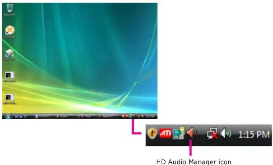
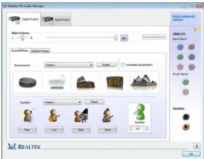
HD Audio Manager
- Connect a S/PDIF audio device to a S/PDIF port. The The Current connected device is dialog box appears. Select the appropriate device then click OK.
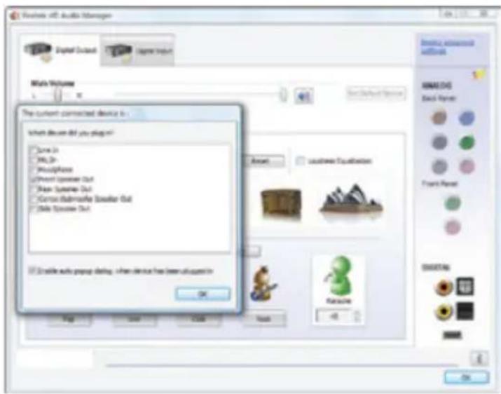
- When you plug a speaker, the Speakers tab will appear. Click the Speakers tab.
In Speaker Configuration, select Stereo, Quadraphonic, 5.1 Speaker, or 7.1 Speaker, then click OK.
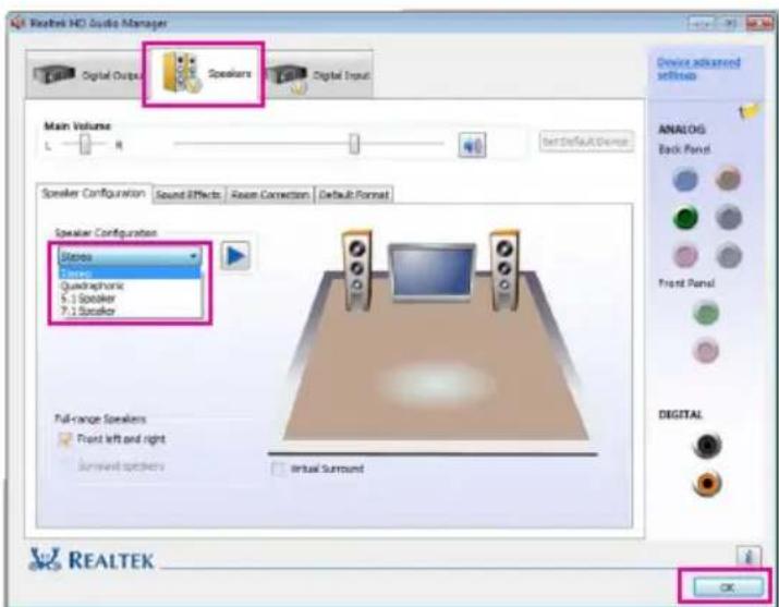
Configuring Sound Effect
Select the sound effect of the headphone or speaker in the Sound Effect tab.
Activating the AC'97 Front Panel Audio Module
If your chassis comes with an AC'97 front panel audio module, you can activate the AC'97 functionality.
- Click the Tool icon.
- When the Connector Settings dialog box appears, unclick the Disable front panel jack detection check box.
- Click OK.
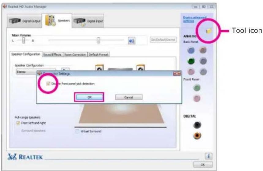
Muting the Back Panel Audio (for HD Audio only)
- Click Device advanced settings located on the upper right corner of the screen.
- Select Mute the rear output device, when a front headphone plugged in.
- Click OK.
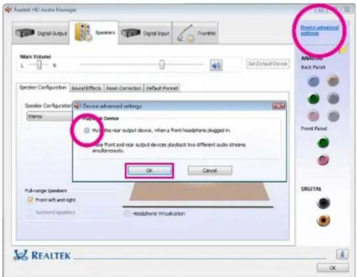
Appendix A - ABS: Auto Boost System

The ABS (Auto Boost System) technology provides the convenience of saving and loading several OC settings. It allows you to use the best OC setting to optimize your system's performance. You can "Auto Boost" your system by simply pressing the
ABS provides the following functions that are easy for users to operate.
- Backup OC profile
- Load OC profile
• Exchange OC profile
Installing ABS
- The ABS utility is included in the provided DVD. Insert the DVD into an optical drive. On the top row of the screen, click the 6th icon to open the Utility menu.
- Click "Auto Boost System".

- The installation wizard is extracting the files needed to install the utility. The wizard will lead you to complete the installation.
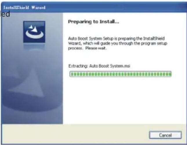
- Setup is now ready to install the utility. Click Next.
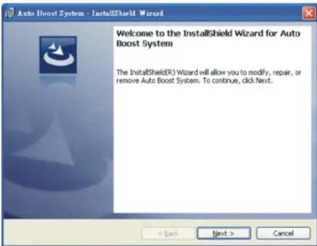
- Click Next to install destination folder or click Change to select another folder.
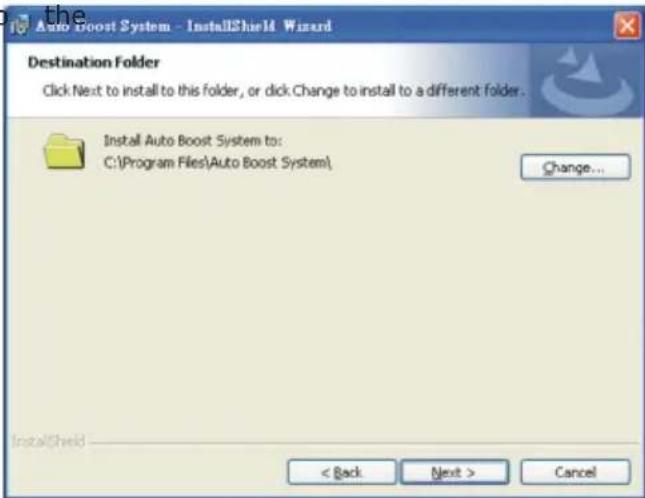
- Click Install to begin the installation.
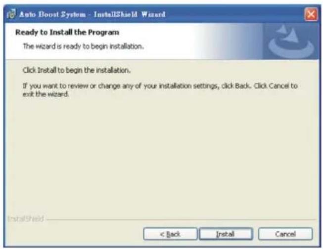
- The installation wizard will copy all the necessary and optimize the ABS features.
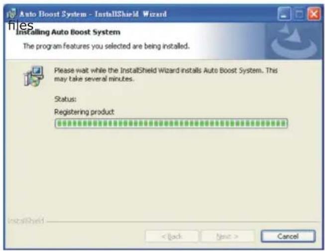
- Click Finish to exit setup.
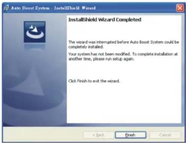
The ABS Utility
- To run the ABS utility, power up your system then press F1. The screen will show the CPU upgrade information. Press "Any Key" to continue.
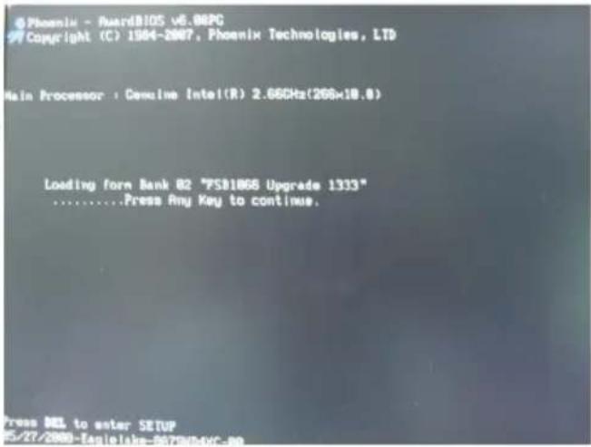
- When the system enters the operating system, the ABS utility will appear and display the system's information. Click Auto Upgrade.
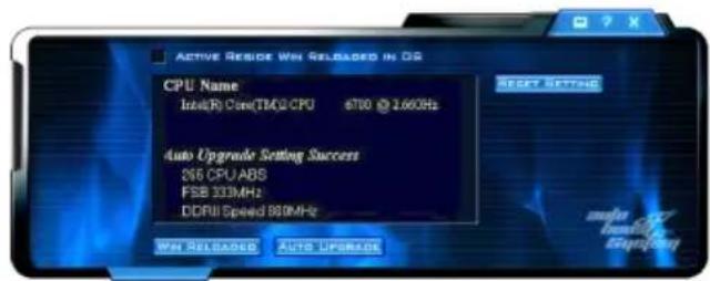
- The screen on the right will appear.

- Select the system board in use.

- Click Confirm.

- ABS supports Win Reloaded and Auto Upgrade features. Click Auto Upgrade.
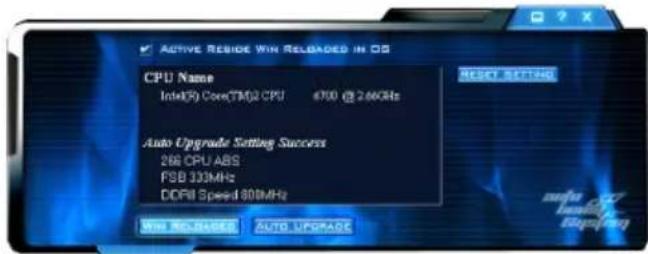
- Click Backup.

- The default settings will appear on the screen. Click Save.
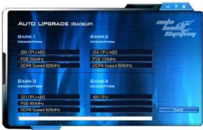
- Enter a name for the fault setting then click Save. You have just created a backup file of board's default setting.
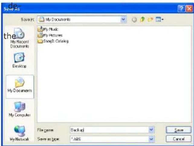
- If in any case a new OC setting causes system instability, you can always retrieve the backup file saved earlier by clicking Reload.

- Click Open.
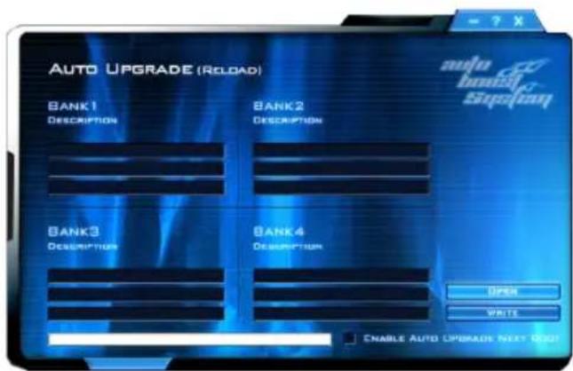
- Select the backup file click Open.
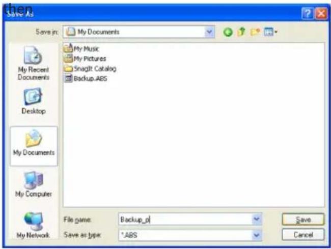
- Click Write to load Banks 1-4 into the BIOS.
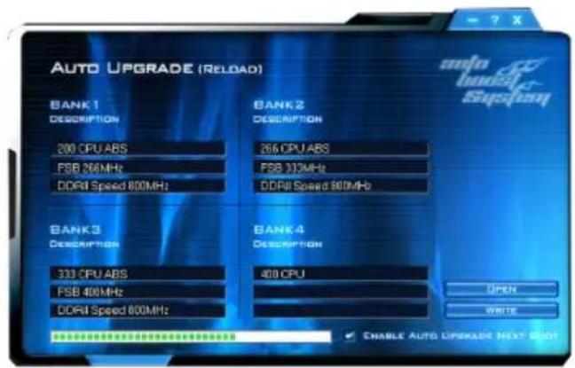
If you want the system to auto upgrade the setting the next time you boot system, click "Enable Auto Upgrade Next Boot".

- Click Yes to reboot.


Important:
-
We strongly recommend that you backup the default setting. If in any case your overclock setting causes system instability, you can always retrieve the default setting by reloading the backup file.
-
Everytime you change the BIOS settings, remember to always backup the file because the previous backup file will not match the new BIOS settings therefore it will not work.
Troubleshooting Checklist
This chapter of the manual is designed to help you with problems that you may encounter with your personal computer. To efficiently troubleshoot your system, treat each problem individually. This is to ensure an accurate diagnosis of the problem in case a problem has multiple causes.
Some of the most common things to check when you encounter problems while using your system are listed below.
- The power switch of each peripheral device is turned on.
- All cables and power cords are tightly connected.
- The electrical outlet to which your peripheral devices are connected is working. Test the outlet by plugging in a lamp or other electrical device.
- The monitor is turned on.
- The display's brightness and contrast controls are adjusted properly.
- All add-in boards in the expansion slots are seated securely.
- Any add-in board you have installed is designed for your system and is set up correctly.
Monitor/Display
If the display screen remains dark after the system is turned on:
- Make sure that the monitor's power switch is on.
- Check that one end of the monitor's power cord is properly attached to the monitor and the other end is plugged into a working AC outlet. If necessary, try another outlet.
- Check that the video input cable is properly attached to the monitor and the system's display adapter.
- Adjust the brightness of the display by turning the monitor's brightness control knob.
The picture seems to be constantly moving.
- The monitor has lost its vertical sync. Adjust the monitor's vertical sync.
- Move away any objects, such as another monitor or fan, that may be creating a magnetic field around the display.
- Make sure your video card's output frequencies are supported by this monitor.
The screen seems to be constantly wavering.
- If the monitor is close to another monitor, the adjacent monitor may need to be turned off. Fluorescent lights adjacent to the monitor may also cause screen wavering.
Power Supply
When the computer is turned on, nothing happens.
- Check that one end of the AC power cord is plugged into a live outlet and the other end properly plugged into the back of the system.
- Make sure that the voltage selection switch on the back panel is set for the correct type of voltage you are using.
- The power cord may have a "short" or "open". Inspect the cord and install a new one if necessary.
Floppy Drive
The computer cannot access the floppy drive.
- The floppy diskette may not be formatted. Format the diskette and try again.
- The diskette may be write-protected. Use a diskette that is not write-protected.
- You may be writing to the wrong drive. Check the path statement to make sure you are writing to the targeted drive.
- There is not enough space left on the diskette. Use another diskette with adequate storage space.
Hard Drive
Hard disk failure.
- Make sure the correct drive type for the hard disk drive has been entered in the BIOS.
- If the system is configured with two hard drives, make sure the bootable (first) hard drive is configured as Master and the second hard drive is configured as Slave. The master hard drive must have an active/bootable partition.
Excessively long formatting period.
If your hard drive takes an excessively long period of time to format, it is likely a cable connection problem. However, if your hard drive has a large capacity, it will take a longer time to format.
Serial Port
The serial device (modem, printer) doesn't output anything or is out-putting garbled characters.
- Make sure that the serial device's power is turned on and that the device is on-line.
- Verify that the device is plugged into the correct serial port on the rear of the computer.
- Verify that the attached serial device works by attaching it to a serial port that is working and configured correctly. If the serial device does not work, either the cable or the serial device has a problem. If the serial device works, the problem may be due to the onboard I/O or the address setting.
- Make sure the COM settings and I/O address are configured correctly.
Keyboard
Nothing happens when a key on the keyboard was pressed.
- Make sure the keyboard is properly connected.
- Make sure there are no objects resting on the keyboard and that no keys are pressed during the booting process.
System Board
- Make sure the add-in card is seated securely in the expansion slot. If the add-in card is loose, power off the system, re-install the card and power up the system.
- Check the jumper settings to ensure that the jumpers are properly set.
- Verify that all memory modules are seated securely into the memory sockets.
- Make sure the memory modules are in the correct locations.
- If the board fails to function, place the board on a flat surface and seat all socketed components. Gently press each component into the socket.
- If you made changes to the BIOS settings, re-enter setup and load the BIOS defaults.
Appendix C - Debug LED Post and Troubleshooting
General Debug LED POST and Troubleshooting
| POST (hex) | Debug Code Action | BIOS Program Definition | Possible Cause | Solution |
| Power on | Nonc, blank | Nil | 1. CMOS jumper is set at pins 2-3. | 1. Set the CMOS jumper to pins 1-2 (default). |
| 2. 5Vsb of PSU is insufficient. (Minimum required - 2A) | 2. Replace a suitable PSU. | |||
| 00 | Power on -> Stopped at 00 | BIOS program starts to set VID/FID to initialize CPU. (Boot Block area). | 1. Mixed-up BIOS data. | 1. Clear the CMOS data. |
| 2. Defective CPU connection. | 2. Remove and reinstall the CPU. | |||
| 3. Incompatible PSU. | 3. Replace a suitable PSU. | |||
| 4. No CPU power. | 4. Inspect the 12V connection. | |||
| 5. Reset button short-circuited. | 5. Inspect the cable that connects the reset button to the front panel connector. | |||
| 00 | Power on -> 00 -> Reset -> Looping | CPU VID is incorrect. | PSU does not comply with the system's requirement. | Replace a PSU that will provide adequate power to the system. |
| A0 | 00->C1->Stopped at A0 | A0~AF Definition: Initializing memory check code. | 1. Incompatible memory modules. | 1. Remove and reinstall the memory modules. |
| 2. Mixed-up BIOS data. | 2. Clear the CMOS data. | |||
| b8 | 00->C1->Stopped at b8 | B0~BF Definition: Initializing memory devices check code (registers). | 1. Mixed-up BIOS data. | 1. Clear the CMOS data. |
| 2. Incompatible memory modules. | 2. Remove and reinstall the memory modules. | |||
| 3. Incompatible PCI devices. | 3. Remove and reconnect the PCI devices. | |||
| C0 | 00->Stopped at C0 | Initializing memory. | 1. Probing for failed memory devices. | 1. Make sure the memory modules are installed properly in the slots. |
| 2. SPD value is lost or empty. | 2. Replace the memory modules. |
| POST (hex) | Debug Code Action | BIOS Program Definition | Possible Cause | Solution |
| C1 | 00 -> C0 -> Stopped at C1(00 -> C0 -> C1 -> Reset -> Looping) | Detecting memory.Detecting DRAM size and type.ECC auto-detection of L2 cache. | 1. Incompatible memory modules. | 1. Remove and reinstall the memory modules. |
| 2. Overclocking issue (tight DRAM timing). | 2. Clear the CMOS then load the default speed. | |||
| 3. One of the memory modules is defective. | 3. Try installing a single module only. | |||
| C3/C5 | C0 -> C1 -> Stopped at C3/C5(C0 -> C1 -> C3 -> Reset -> Looping) | Expanding compressed BIOS code to the DRAM. | 1. Tight DRAM timing (system is unstable). | 1. Clear the CMOS then load the default speed. |
| 2. Insufficient DRAM voltage. | 2. Increase the DRAM's voltage. | |||
| 3. Overclocking issue. | 3. Remove and reinstall the memory modules. | |||
| CF | Shutdown -> Stopped at CF(Shutdown -> CF -> Reset) | Resume on S1/S3 failed. | 1. Insufficient DRAM voltage. | 1. Increase the DRAM's voltage. |
| 2. Incompatible memory modules. | 2. Remove and reinstall the memory modules. | |||
| 3. Overclocking issue (tight DRAM timing). | 3. Load the default DRAM speed. | |||
| 4. BIOS issue. | 4. Upgrade to the latest BIOS. | |||
| E0 | C0 -> C1 -> Stopped at E0 | E0-EF Definition: Initializing PCIE device check code. | 1. Mixed-up BIOS data. | 1. Clear the CMOS data. |
| 2. Incompatible PCI devices. | 2. Remove and reinstall the PCI device. |
| POST (hex) | Debug Code Action | BIOS Program Definition | Possible Cause | Solution |
| 25 | 00 -> C1 -> C3 -> Stopped at 25 | Enumerating PCI bus number.Assigning memory & I/O resource -searching for a valid VGA device & VGA BIOS then placing it in C000:0. | 1. Incompatible PCI devices. | 1. Remove all PCI/PCIE devices and leave only the graphics card to test first. Test the devices one at a time to determine the one with problem. |
| 2. Incompatible USB devices. | 2. Remove all USB devices including the USB keyboard and instead use a PS/2 keyboard to test. | |||
| 3. Defective graphics card.(VGA BIOS did not initialize) | 3. Replace the graphics card. | |||
| 4. The graphics card was not installed properly. | 4. Remove and reinstall the graphics card. | |||
| 26 | 00 -> C1 -> C3 -> Stopped at 26 | Initializing display card.Initializing onboard clock generator.Disabling respective clock resource to empty PCI & DIMM slots.Initializing onboard PWM3.Initializing onboard H/W monitor devices. | 1. Defective graphics card. | 1. Replace the graphics card. |
| 2. Initialized wrong BIOS process.(Clock-gen circuit / Super IO circuit) | 2. Clear the CMOS data. | |||
| 41 | C3 -> 25 -> 26 -> Stopped at 41 | Initializing the FDD device. | Detected floppy error. | Unplug the FDD cable and check for errors or check the BIOS settings. |
| * Mixed-up BIOS data could be one of the causes too. | * Replace a new BIOS chip. | |||
| 50 | Power on -> Stopped at 50 | Initializing USB devices. | 1. USB failed to boot. (BBS issue) | 1. Clear the CMOS data first. |
| 2. Incompatible USB devices. | 2. Try connecting the device to another USB port.3. Test the USB devices one by one.4. Set the USB power source to 5V by means of the 5V/5Vsb select jumper. |
| POST (hex) | Debug Code Action | BIOS Program Definition | Possible Cause | Solution |
| 75 | Power on -> Stopped at 75 | Initializing storage devices. (Probing for IDE devices or SATA devices) | 1. Lost power source of some devices. | 1. Inspect the power cable connection. |
| 2. Incompatible SATA or PATA device. | 2. Inspect the IDE cable connection or replace another PATA/ SATA device. | |||
| 3. CD-ROM's spin took too long. | 3. Remove the disc, if present, from the CD-ROM device. | |||
| 7F | Power on -> Stopped at 7F* Checksum error always appear after the BIOS default has been loaded. | BIOS setup module in progress. Reporting BIOS check errors. Waiting for keys: DEL key to load the BIOS default. F1 key to continue. | 1. Checksum error occurred. (Change/add devices such as CPU/ DRAM) | 1. Load the optimized default setting of the BIOS. |
| 2. Error occurred after clearing the CMOS. | 2. Alter or adjust the BIOS setting. | |||
| 3. Onboard battery is depleted. | 3. Replace a new battery. | |||
| 4. Overclocking issue. | 4. Decrease the overclock range. | |||
| * The battery circuit of the MB is defective. | * RMA action required. | |||
| FF | Power on -> Run to FF* Blank Screen | Boot attempt (INT 19h) System booted normally. | Normal Operation | Nil |
| * The graphics card was not connected properly or it is defective. | * Remove and reinstall the graphics card. |
Abnormal Debug LED POST and Troubleshooting
| POST (hex) | Debug Code Action | BIOS Program Definition | Possible Cause | Solution |
| 79 | Power on -> Prompt Stopped at 79 | There is no “79” definition on the Award BIOS code.(BIOS program executed the wrong process therefore showing the wrong POST code.) | 1. Mixed-up BIOS data. | 1. Clear the CMOS data. |
| 2. MB is defective.(NB chip may be defective.) | 2. RMA action required. | |||
| 88 | Power on -> Prompt Stopped at 88 | There is no “88” definition on the Award BIOS code.(BIOS program executed the wrong process therefore showing the wrong POST code.) | 1. Mixed-up BIOS data. | 1. Clear the CMOS data. |
| 2. MB is defective.(NB chip may be defective.) | 2. RMA action required. | |||
| FF | Power on -> Prompt Stopped at FF | Definition: BIOS process completed.(BIOS program executed the wrong process therefore showing the wrong POST code.) | 1. Mixed-up BIOS data. | 1. Clear the CMOS data. |
| 2. MB is defective.(NB chip may be defective.) | 2. RMA action required. |
Index
Clearing CMOS Data
312312

1-2 On: Normal
Clear CMOS Data
(default)
- Wait for 5 seconds then move the jumper cap back to pins 1-2.
Totally Discharging the Motherboard
Unplug the AC power and remove the battery for 5 minutes the the battery and plug the AC power back on.