
LA1550TS - Screen Planar - Free user manual and instructions
Find the device manual for free LA1550TS Planar in PDF.


| Product Type | LCD Monitor |
| Screen Size | 15 inches (diagonal) |
| Native Resolution | 1024 x 768 |
| Display Technology | LCD with CCFL backlight |
| Aspect Ratio | 4:3 |
| Touchscreen | Yes (USB transmitter and touch driver CD included) |
| Input Connectors | VGA (D-SUB), USB (for touch) |
| Power Supply | External AC/DC adapter, 110V AC input |
| VESA Mount Compatible | Yes (M4 screws, max length 8mm, sustain at least 7kg) |
| OSD Languages | English, French, Japanese, German, Spanish, Italian, Traditional Chinese, Simplified Chinese |
| Hazardous Location Rating | Class I, Division 2, Groups A, B, C, D |
| Front Panel Controls | Menu, Brightness (+), Contrast (-), Select/Auto Adjustment |
| Package Contents | LCD Display, Power Cord, DC Power Supply, Wall-to-Monitor Cable, USB Transmitter, Touch Driver CD, Manual, VESA Mount Screws (M4x8) |
| Weight (approx.) | 7 kg (stand must sustain at least 7kg) |
| Cleaning (Screen) | Soft cloth with mild window cleaner or 50/50 water/isopropyl alcohol |
| Cleaning (Housing) | Soft cloth moistened with mild detergent |
| Safety Warnings | Do not open or disassemble; explosion hazard in hazardous areas; disconnect power before cleaning |
| Compliance | FCC Class A, Class I Division 2 |
| Special Feature | Paint Booth Cable for hazardous environment installations |
| Auto Adjustment | Yes (optimizes image automatically) |
Frequently Asked Questions - LA1550TS Planar
User questions about LA1550TS Planar
0 question about this device. Answer the ones you know or ask your own.
Ask a new question about this device
Download the instructions for your Screen in PDF format for free! Find your manual LA1550TS - Planar and take your electronic device back in hand. On this page are published all the documents necessary for the use of your device. LA1550TS by Planar.
USER MANUAL LA1550TS Planar
The information contained in this document is subject to change without notice. This document contains proprietary information that is protected by copyright. All rights are reserved. No part of this document may be reproduced, translated to another language or stored in a retrieval system, or transmitted by any means, electronic, mechanical, photocopying, recording, or otherwise, without prior written permission. Windows is registered trademark of Microsoft, Inc.
Other brand or product names are trademarks of their respective holders.

Important Recycle Instruction:
Lamp(s) inside this product contains mercury. This product may contain other electronic waste that can be hazardous if not disposed of properly. Recycle or dispose in accordance with local, state or federal laws. For more information, contact the Electronic Industries Alliance at www.eiae.org. For lamp specific disposal information, check www.lamprecycle.org.
Table of Contents
I. Usage Notice 4
Precautions 6
II. Package Overview 7
III. Installation 8
Product Overview 8
VESA Mount your Monitor 9
Connect the Display 10
Warning-Explosion Hazard 10
Special installaon Instrucons 11
IV. User Controls 12
Front Panel Controls 12
How to use the OSD 13
On-Screen Display Menus 14
V. Appendix 15
Troubleshooting 15
Warning Signal 146
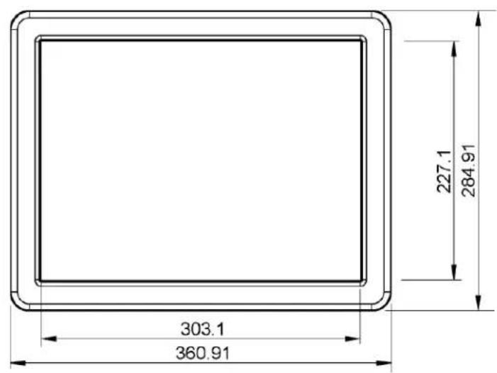
Product Dimensions 147
Compatibility Modes 16
Manufacturer's Instructions 18
Compliance Information 20
I. Usage Notice

Warning – Please do not open or disassemble the product as this cause electric shock.

This apparatus is suitable for use in Class I, Division 2 group A, B, C, D or classified locations.

WARNING- EXPLOSION HAZARD – DO NOT DISCONNECT EQUIPMENT SS POWER HAS BEEN SWITCHED OFF OR THE AREA IS KNOWN TO BE HAZARDOUS.

AVERTISSEMENT – RISQUE D'ECPLOSION – AVANT DE DECONNECTER EQUIPEMENT, COUPER LE COURANT OU S'ASSURER QUE L'EMPLACEMENT DESIGNE NON DANGEREUX.

WARNING- SUBSTITUTION OF COMPONENTS MAY IMPAIR SUITABILITY CLASS1, DIVISION 2.

AVERTISSEMENT – RISQUE D'EXPLOSION – LA SUBSTITUTION DE POSANTS PEUT RENDRE CE MATERIEL INACCEPTABLE POUR LES ACEMENTS DE CLASSE I, DIVISION 2.
Precautions
Follow all warnings, precautions and maintenance as recommended in this user's manual to maximize the life of your unit.
Do:
- Disconnect the power plug before cleaning
- Touch screen surfaces may be cleaned using a soft clean cloth moistened with mild window glass commercial cleaners or 50/50 mixture of water and isopropyl alcohol.
- Use a soft cloth moistened with mild detergent to clean the display housing.
- Use only high quality and safety approved AC/DC adapter.
- Disconnect the power plug from AC outlet if the product is not going to be used for an extended period of time.
Don't:
- Do not touch the LCD display screen surface with sharp or hard objects.
- Do not use abrasive cleaners, waxes or solvents for your cleaning.
- Do not operate the product under the following conditions:
■ Extremely hot, cold or humid environment
■ Areas susceptible to excessive dust and dirt
- Near any appliance generating a strong magnetic field
- In direct sunlight
II. Package Overview

natural_image
Black rectangular object with diagonal striped pattern, no visible text or symbolsLCD Display

natural_image
Line drawing of a multi-pin electrical plug with leads (no text or symbols)Power Cord

natural_image
Line drawing of a cable-winding connector with connectors and a rectangular housing (no text or symbols)DC Power Supply
natural_image
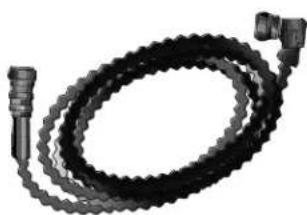
Coiled black mechanical component with two connectors (no text or symbols visible)Wall to monitor Cable

natural_image
Line drawing of a USB cable with a square connector (no text or symbols)USB Transmitter

Touch Driver CD

natural_image
Blank sheet of paper with no visible text or markingsManual

VESA Mount Screws
M4*8
III. Installation
Product Overview
- Front View

natural_image
Simple line drawing of a rectangular frame with rounded corners (no text or symbols)VESA Mount your Monitor
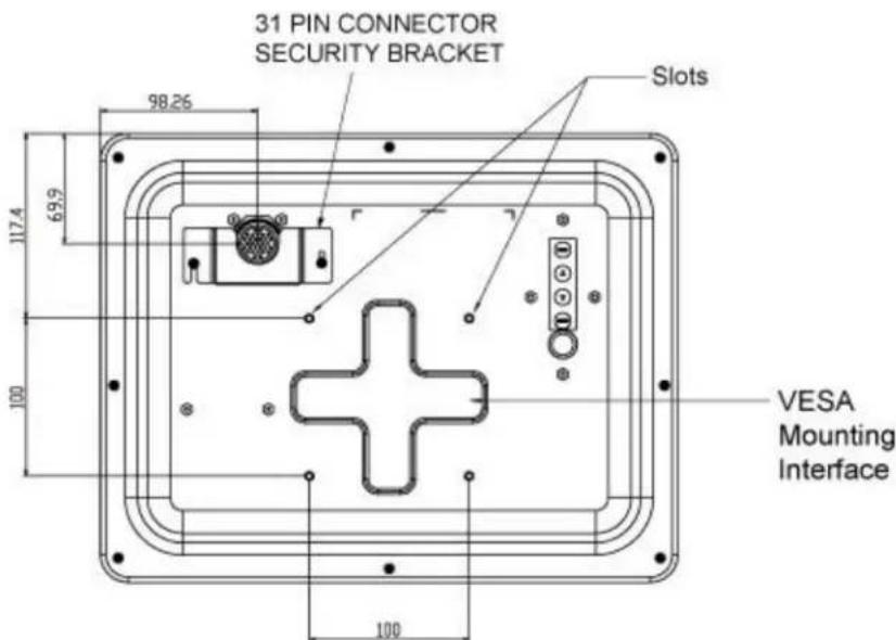
This monitor conforms to the VESA Flat Panel Mounting Physical Mounting Interface Standard which defines a physical mounting interface for flat panel monitors, and corresponding with the standards of flat panel monitor mounting devices, such as wall and table arms. The VESA mounting interface is located on the back of your monitor.
To mount the monitor on a swing arm or other mounting fixture, follow the instructions included with the mounting fixture to be used. Please note to mount your monitor to the devices (either mounting fixture or swing arm) what conforms to the UL listed.

Warning!
Please select the proper screws! The distance between the back cover surface and the bottom of the screw hole is 8mm. Please use four M4 screws diameter with the maximum length of 8mm to mount your monitor.
Please note the mounting stand shall be able to sustain at least 7Kg weight.
Connecting the Display
To setup this display, please refer to the following figure and procedures.
- Be sure all equipments are turned off.
- Connect the Paint Booth Cable to the connector on the back cover of the monitor.
- Connect the Extension Cable to the Paint Booth Cable and the other end to PC.
- Connect D-SUB connector from the extension Cable to VGA output connector on PC.
- Connect RJ-45 connector from extension cable to USB Transmitter device and connect USB Transmitter device to PC USB port.
- Connect power connector to 110VAC power brick..
- Connect Power cord to power brick and the other end into AC socket.

Notice!
To ensure the LCD display works well with your computer, please configure the display mode of your graphics card to make it less than or equal to 1024 x 768 resolution and make sure the timing of the display mode is compatible with the LCD display.
We have listed the compatible “Video Modes” of your LCD display in the appendix (on page 18) for your reference.

Attention
This equipment is suitable for use in Class I, Division 2, Group A, B, C, D, or Non-Hazardous Locations Only.
Warning-Explosion Hazard
Do not disconnect equipment unless power has been switched OFF or the area is known to be non-hazardous.
Special installation Instructions
Class I DIV 2
HAZARDOUS LOCATION

flowchart
graph TD
    A["Wall Mount Plate"] --> B["If penetrating wall drill 1.625-1.75" hole"]
    A --> C["Power Connector"]
    A --> D["USB"]
    A --> E["VGA"]
    A --> F["Local Monitor"]
    A --> G["Computer"]
    H["Seperating Wall"] --> I["Power Brick"]
    I --> J["Output"]
Install system as per diagram above by qualified personnel in accordance with NFPA 70 (NEC) Article 500 (contact an electrician if you have any questions or concerns about the installation).
IV. User Controls
Front Panel Controls

natural_image
Technical line drawing of a device casing with a central cross-shaped component and control panel (no text or symbols)
| No | Icon | Control | Function |
| 1. | Menu | Menu button | Display/Exits the OSD menu |
| 2. | ▲ | BrightnessPlusClockwise | Enter brightness of the OSD.Increase value of the adjustment item.Select item clockwise. |
| 3. | ▼ | ContrastMinusCounter-Clockwise | Enter contrast of the OSD.Decrease value of the adjustment item.Select item counter-clockwise |
| 4. | Select | SelectAuto Adjust | Select: Select the adjustment items from OSD menu.Auto Adjust: Activate the “Auto Adjustment” function to obtain the optimum image. |
How to Use the OSD Menus
- Press the "MENU" button to pop up the "on-screen menu" and press "▼" or "▲" to select among the four Main Menus.
- Choose the adjustment items by pressing the "SELECT / AUTO" button.
- Adjust the value of the adjustment items by pressing the "▲" or "▼" button.
(1) The OSD menu will automatically close, if you have left it idle for a pre-set time.
(2) To disable the OSD / Power menu buttons, please follow the instructions below:
(Please note: the monitor has to be turned ON with a valid signal preset)
a. Press and hold the "Menu" and "Power" key simultaneously for 1 second.
b. The word "OSD Lock" / "Power Lock" will appear for 2 seconds on the monitor.
This indicates that all the front buttons, with the exception of the power button, are now disabled.
(3) To enable the OSD / Power menu buttons, please follow the instructions below.
(Please note: the monitor has to be turned ON with a valid signal present.)
a. Press and hold the "Menu" and "Power" key simultaneously for 1 second.
b. The word "OSD Unlock" / "Power Unlock" will appear for 2 seconds on the monitor. This indicates that all the front buttons are now enabled.
On-Screen Display Menus
Main OSD Menu:
| MAIN MENU | Control | Function |
| Contrast | 0-100 | Adjusts the maximum luminance level of the monitor. |
| Brightness | 0-100 | Adjusts the backlight of the monitor. |
| Auto Adjust | No/Yes | The screen is moved horizontally right and left (1 pixel pitch increment.) |
| Left / Right | 0-100 | The screen is moved horizontally right and left (1 pixel pitch increment.) |
| Down / Up | 0-100 | The screen is moved vertically up and down (1 line increment.) |
| Horizontal Size | 0-100 | The ratio of dividing frequency of the dot clock is adjusted. |
| Fine | 0-100 | The phase of the dot clock is adjusted. |
| OSD Left / Right | 0-100 | Adjusts the OSD menu screen position left or right. |
| OSD Up / Down | 0-100 | Adjusts the OSD menu screen position up or down. |
| OSD Time Out | 5-60 | Adjusts the amount of the OSD menu is displayed. |
| OSD Language | Select the language used for the OSD menu among English, French, Japanese, Deutsch, Spanish, Italian, Traditional Chinese and Simplified Chinese. | |
| Factory Reset | NO / YES | Restores original factory settings. |
| RGB | Sets the color temperature. 9300, 6500, 5500, 7500 user. |
V. Appendix
Troubleshooting
If you are experiencing trouble with the LCD display, refer to the following. If the problem
persists, please contact your local dealer or our service center.
Problem: No image appears on screen.
▶ Check that all the I/O and power connectors are correctly and well connected described in the "Installation" section.
▶ Make sure the pins of the connectors are not crooked or broken.
Problem: Partial Image or incorrectly displayed image.
▶ Check to see if the resolution of your computer is higher than that of the LCD display.
▶ Reconfigure the resolution of your computer to make it less than or equal to 1024 x 768.
Problem: Image has vertical flickering line bars.
▶ Use "Fine" to make an adjustment.
▶ Check and reconfigure the display mode of the vertical refresh rate of your graphic
card to make it compatible with the LCD display.
Problem: Image is unstable and flickering
▶ Use "Fine" to make an adjustment.
Problem: Image is scrolling
▶ Check and make sure the VGA signal cable (or adapter) is securely connected.
▶ Check and reconfigure the display mode of the vertical refresh rate of your graphics
card to make it compatible with the LCD Display.
Problem: Vague image (characters and graphics)
▶ Use "Fine" to make an adjustment. If this problem still exists, use "Horizontal size" to make an adjustment.
Warning Signal
If you see warning messages on your LCD screen, this means that the LCD display cannot receive a clean signal from the computer graphics card.
There may be three sources for this problem. Please check the cable connections or contact your local dealer or our service center for more information.
No Signal
This message means that the LCD Display has been powered on but it cannot receive any signal from the computer graphics card. Check all the power switches, power cables and VGA signal cable.
➢ Going to Sleep
The LCD is under the power saving mode. In addition, the LCD will go into this sleep mode when experiencing a sudden signal disconnecting problem.
Out of Range
This message means that the signal of the computer graphic card is not compatible with the LCD display. When the signal is not included in the "Video Modes" list we have listed in the Appendices of this manual, the LCD monitor will display this message.
P


Compatibility Modes
| Mode | Resolution | H-Frequency (KHz) | V-Frequency (Hz) |
| VGA | 720 x 400 | 31.47 | 70 |
| VGA | 640 x 480 | 31.47 | 60 |
| MAC XGA | 640 x 480 | 35 | 66 |
| VESA VGA | 640 x 480 | 37.86 | 72 |
| VESA SVGA | 640 x 480 | 37.5 | 75 |
| VESA SVGA | 800 x 600 | 35.16 | 56 |
| VESA SVGA | 800 x 600 | 37.88 | 60 |
| VESA SVGA | 800 x 600 | 46.88 | 75 |
| VESA XGA | 800 x 600 | 48.08 | 72 |
| MAC XGA | 832 x 624 | 49.72 | 75 |
| VESA XGA | 1024 x 768 | 48.36 | 60 |
| SUN XGA | 1024 x 768 | 52.45 | 66 |
| VESA XGA | 1024 x 768 | 56.48 | 70 |
| VESA XGA | 1024 x 768 | 60.02 | 75 |
Manufacturer's Instructions
This apparatus is suitable for use in Class I, Division 2 groups, or unclassified locations. Control drawing:

flowchart
graph TD
    A["INVERTER"] --> B["USB EXTENDER RECEIVER"]
    A --> C["TOUCH CONTROLLER"]
    B --> D["DC/DC POWER BOARD"]
    C --> D
    D --> E["INTERFACE BOARD"]
    E --> F["OSD BOARD"]
    G["VGA POWER USB Complex connector"] --> D
    H["CCFL BACKLIGHT"] --> I["LCD PANEL"]
    I --> J["3mm Touch Screen"]
WARNING: EXPOSURE TO SOME CHEMICALS MAY DEGRADE THE SEALING PROPERTIES OF MATERIALS USED IN THE DEVICES.
WARNING: EXPLOSION HAZARD. DO NOT DISCONNECT WHILE THE CIRCUIT IS LIVE OR UNLESS THE AREA IS KNOWN TO BE FREE OF IGNITIBLE CONCENTRATIONS.
Compliance Information
Federal Communication Commission Radio
Frequency International Statement
This equipment has been tested and found to comply with the limits for a Class A digital device pursuant to Part 15 of the FCC Rules. These limits are designed to provide reasonable protection against harmful interference with the equipment is operated in a commercial environment. This equipment generates, uses and can radiate radio frequency energy and, if not installed and used in accordance with the instruction manual, may cause harmful interference to radio communications. Operation of this equipment in a residential area is likely to cause harmful interference in which case the user will be required to correct the interference at his own expense.
| Revision Control | |
| DATE: | DESCRIPTION: |
| Oct 2009 | Document number 020-0996-00 Rev. A |
| June 2011 | Document number 020-0996-00 Rev. B |
Planar Systems, Inc.
Corporate Headquarters
1195 NW Compton Drive
Beaverton, OR 97006-1992
Planar Customer Support
Telephone:
US: 1-866-PLANAR1 (866) 752-6271
Outside US: (503) 748-5799
E-mail: PlanarSupport@planar.com
Online Technical Library: http://www.planar.com/support
Hours: M-F, 3am-7pm ET, 11am-3am GMT
© 2008 Planar Systems, Inc. Planar is a registered trademark of Planar System, Inc.
Other brands and names are the property of their respective owners.
Technical information in this document is subject to change without notice
- Important Recycle Instruction:
- Table of Contents
- Usage Notice
- Precautions
- Do:
- Don't:
- Package Overview
- Installation
- Product Overview
- - Front View
- VESA Mount your Monitor
- Warning!
- Connecting the Display
- Notice!
- Attention
- Warning-Explosion Hazard
- Special installation Instructions
- User Controls
- Front Panel Controls
- How to Use the OSD Menus
- On-Screen Display Menus
- Appendix
- Troubleshooting
- Problem: No image appears on screen.
- Problem: Partial Image or incorrectly displayed image.
- Problem: Image has vertical flickering line bars.
- Problem: Image is unstable and flickering
- Problem: Image is scrolling
- Problem: Vague image (characters and graphics)
- Warning Signal
- No Signal
- ➢ Going to Sleep
- Out of Range
- Manufacturer's Instructions
- Compliance Information
- Federal Communication Commission Radio
- Frequency International Statement
- Planar Systems, Inc.
- Planar Customer Support
Brand : Planar
Model : LA1550TS
Category : Screen