WR200 - Wi-Fi repeater AUDIO PRO - Free user manual and instructions
Find the device manual for free WR200 AUDIO PRO in PDF.

| Product Type | Wi-Fi Repeater |
| Brand | Audio Pro |
| Model | WR200 |
| Wireless Standard | IEEE 802.11 b/g/n |
| Frequency Band | 2.4 GHz |
| Maximum Wireless Speed | 300 Mbps |
| Number of Antennas | 2 (internal) |
| Ethernet Ports | 1 x RJ-45 (10/100 Mbps) |
| WPS Button | Yes |
| Security | WPA2-PSK, WPA-PSK, WEP |
| Power Input | 5V DC, 1A (micro USB) |
| Power Consumption | 3 W (max) |
| Dimensions (W x D x H) | 80 x 60 x 30 mm |
| Weight | 95 g |
| Operating Temperature | 0°C to 40°C |
| Storage Temperature | -20°C to 70°C |
| Humidity | 10% to 85% non-condensing |
| LED Indicators | Power, Wi-Fi, LAN, WPS |
| Setup Method | Web browser or WPS |
| Compliance | CE, FCC |
| Maintenance | Clean with soft dry cloth |
| Safety | Indoor use only; avoid moisture |
| Repairability | No user-serviceable parts; contact support |
Frequently Asked Questions - WR200 AUDIO PRO
User questions about WR200 AUDIO PRO
0 question about this device. Answer the ones you know or ask your own.
Ask a new question about this device
Download the instructions for your Wi-Fi repeater in PDF format for free! Find your manual WR200 - AUDIO PRO and take your electronic device back in hand. On this page are published all the documents necessary for the use of your device. WR200 by AUDIO PRO.
USER MANUAL WR200 AUDIO PRO
- Extended room to room: up to 20m
- Extended range same room: up to 50m
- Extended range in line of sight: up to 100m
- Wireless range between unit 1 & 2: 10-30m
- Wireless full CD quality sound
- Sample rate: 48 KHz
- Dedicated proprietary protocol
- Master/zone volume relay
SPECIFICATIONS
Type: Wireless extender for Audio Pro network
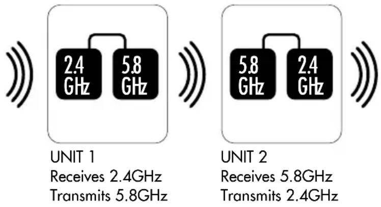
Transmitting/receiving:
Unit 1:
2.4GHz receiver + 5.8GHz transmitter Unit 2:
5.8GHz receiver + 2.4GHz transmitter
Size WxHxD: 95x110x30mm
OVERVIEW & CONTENTS
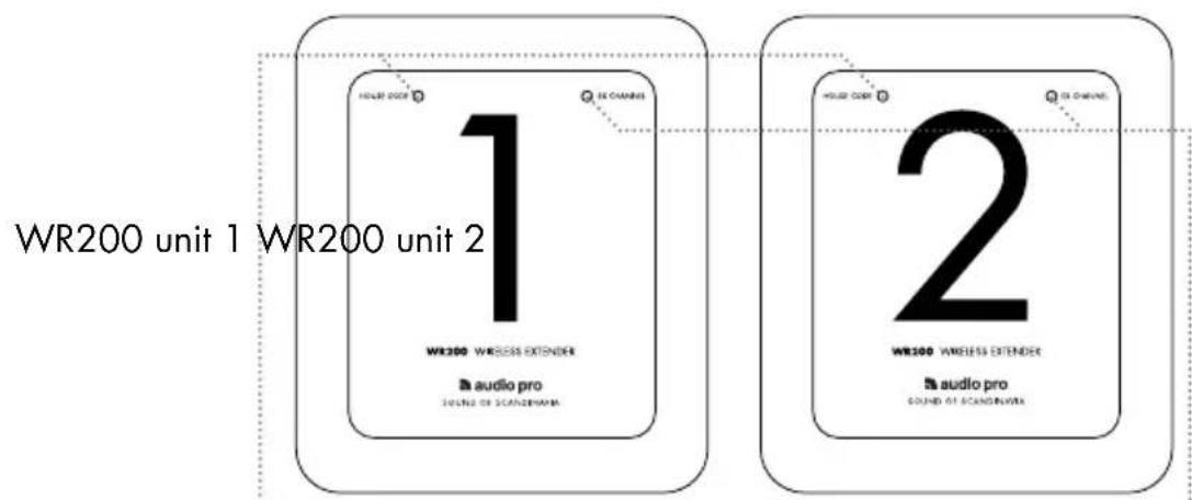
text_image
WR200 unit 1 WR200 unit 2 WR200 WIRELESS EXTENDER audio pro SOUND OF SCANDINUMA 2 WR100 WIRELESS EXTENDER audio pro SOUND OF SCANDINUMAHouse Code LED
Indicates wireless status for 2.4GHz. Solid blue for connection, flashing blue for lost connection. Red for no wireless connection or no transmission.
EX channel LED
Indicates wireless status for 5.8GHz. Solid blue for connection, flashing blue for lost connection. Red for no wireless connection or no transmission.
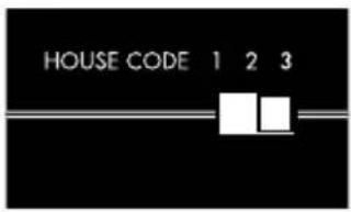
Side: House Code switch
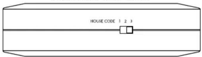
text_image
HOUSE CODE 1 2 3Side: Extender channel switch
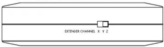
text_image
EXTENDER CHANNEL X Y ZBottom: Power input and line output
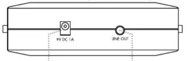
text_image
9V DC 1A LINE OUTConnect to enclosed power adaptor
Connect optional device with line input (stereo/receiver/ powered speakers).
2 x powersupply
natural_image
Two identical black electrical components connected by wires, no text or symbols visibleFUNCTIONALITY AND PERFORMANCE
HOW WR200 WORKS
The WR200 system consists of two units, 1 and 2. Unit 1 is the first unit and receives a signal (2.4GHz) from the TX100 transmitter and then relays the signal on a different band (5.8GHz) to unit 2. Unit 2 then transmits the signal on the 2.4GHz band to all speakers.
Because the 5.8GHz band is stronger but shorter in range than the 2.4GHz band, WR200 will work around any difficult conditions in a house that the wifi signal encounters. We also use the 5.8GHz band to avoid 2.4GHz audio signal conflict.
AVOIDING SIGNAL CONFLICTS BY USING HOUSE CODES
On each unit there are House Code and Extender channel switches. When using WR200, it is important that unit 2 is set to a different House Code than that used by the TX100 transmitter. This is because, if set to the same House Code, unit 1 will receive signals from both TX100 and unit 2 and will not know which signal to use. This would result in a conflict in signals and the WR200 would not function correctly.
EXTENDER CHANNEL
The WR200 has 3 different settings for the internal 5.8GHz channels.
This feature makes it possible to use up to three WR200 systems in series in order to extend network even further. Or if your home has several wifi problems that need to be handled and circumvented. Each pair of WR200s must be set to the same extender channel X,Y or Z.
MASTER AND ZONE VOLUME
All speakers in the Living series can handle master volumes and zone volumes. All volume commands are relayed via WR200. For example, if you have speakers connected before and after the WR200 in zone A, and if you adjust the volume on any speaker in zone A, all the speakers in zone A will be adjusted. The same principle applies for the master volume functionality, which adjusts all speakers on same House Code.
WHEN PLACING WR200
When you position units 1 and 2, you can use the LED indicators as a guide. They show a continuous blue light to indicate that a connection has been established between transmitter and receiver. When correctly placed, all LED's on both units 1 and 2 will show a continuous blue light. Try different placements to achieve the best signal. The TX100 transmitter must be connected to a sound source and have a continuous blue light showing.
The WR200 can be hung on a wall using the hole in the rear.
BASIC CONNECTION
All speakers located within range are set to the same House Code as the TX100.
TX100 transmitter

natural_image
Abstract black curved lines on white background (no text or symbols)Range: 20-100m
UNIT 1
HOUSE CODE: Same as on the TX100 transmitter (1, 2 or 3)

text_image
1 WITH VIDEO OFFICE RADIO:pro PRODUCED BY: 2004-2005UNIT 1
EXTENDER CHANNEL: Set to X, Y or Z
text_image
HOUSE CODE 1 2 3

Range: 15-30m

text_image
EXTENDER CHANNEL X Y ZUNIT 2
HOUSE CODE:
Set to different House Code than TX100.
Example: Set TX100 and UNIT 1 to House Code 1, set UNIT 2 to House Code 2 or 3.
text_image
2 Where is a social network Budging How to be connectedUNIT 2
EXTENDER CHANNEL:
Set to same channel X, Y or Z as on UNIT 1.

natural_image
Abstract black curved lines on white background (no text or symbols)Range: 20-100m
Set all LV-speakers to same House Code as UNIT 2 in order to receive a signal.
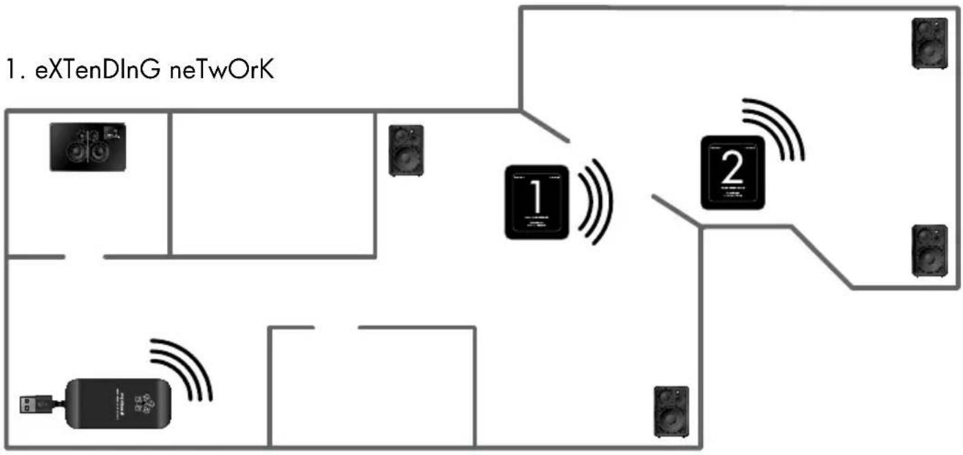
eXamPle COnneCTIOns
flowchart
graph TD
    A["1. eXTenDlnG neTwOrK"] --> B["Component 1"]
    A --> C["Component 2"]
    B --> D["Speaker 1"]
    B --> E["Speaker 2"]
    C --> F["Speaker 1"]
    C --> G["Speaker 2"]
    D --> H["Speaker 1"]
    D --> I["Speaker 2"]
    E --> J["Speaker 1"]
    E --> K["Speaker 2"]
    F --> L["Speaker 1"]
    F --> M["Speaker 2"]
    G --> N["Speaker 1"]
    G --> O["Speaker 2"]
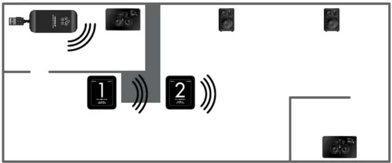
2. ByPass DIflCulT wall COnDITIOns
flowchart
graph TD
    A["User"] --> B["Device 1"]
    B --> C["Control Unit 1"]
    C --> D["Device 2"]
    D --> E["Device 3"]
    E --> F["Device 4"]
    style C fill:#000,stroke:#000,color:#fff
    style D fill:#000,stroke:#000,color:#fff
    style E fill:#000,stroke:#000,color:#fff
    style F fill:#000,stroke:#000,color:#fff
3. ByPass DiffICulT fLOOr COnDITIOns
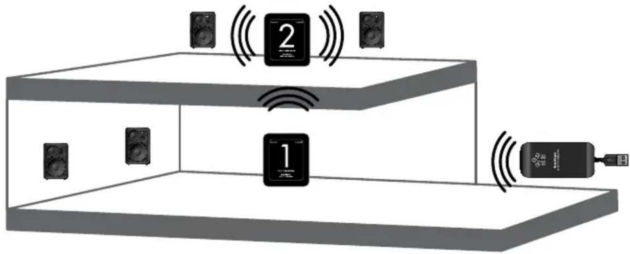
text_image
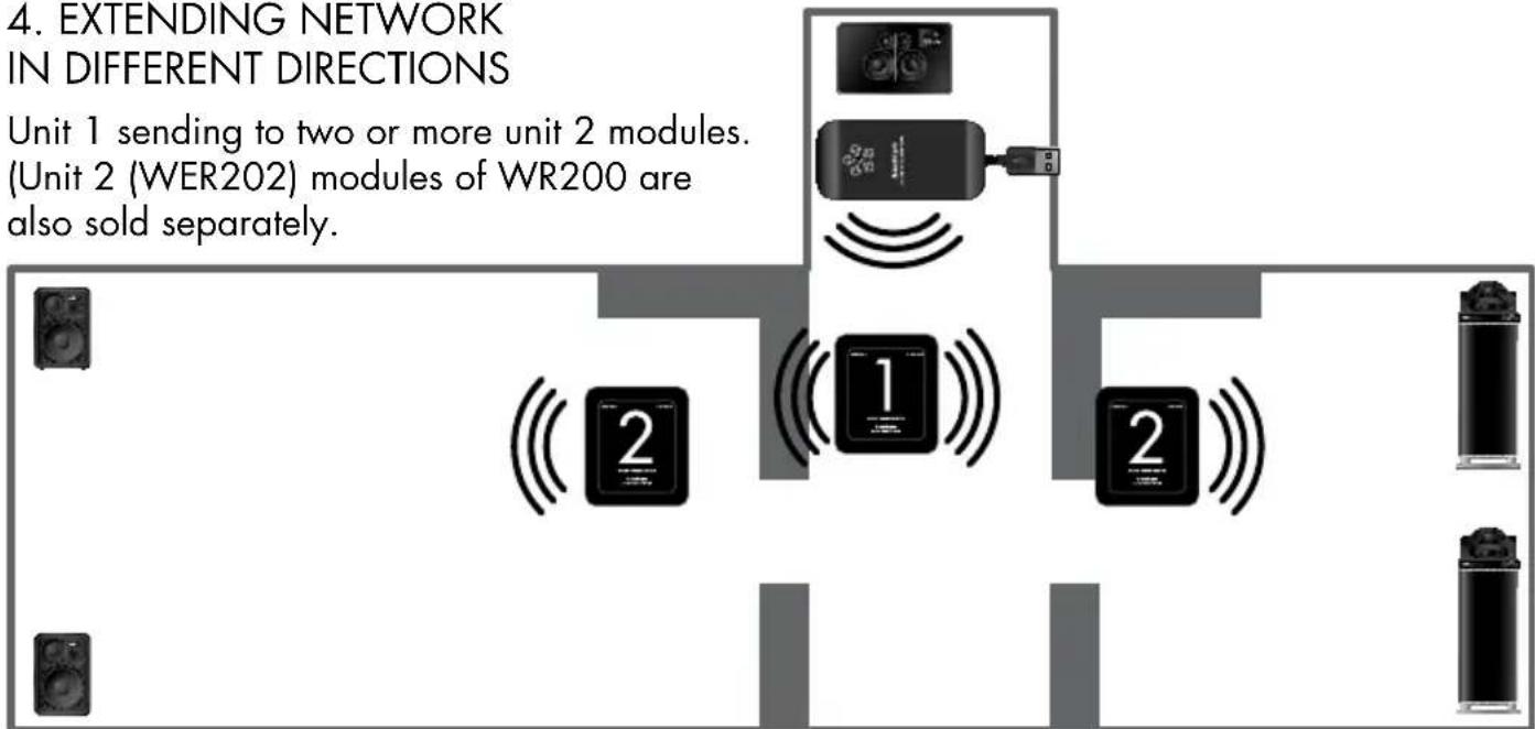
Diagram showing audio equipment setup with speaker, audio device, and connected devices labeled 1 and 24. EXTENDING NETWORK IN DIFFERENT DIRECTIONS
Unit 1 sending to two or more unit 2 modules. (Unit 2 (WER202) modules of WR200 are also sold separately.
flowchart
graph TD
    A["Unit 1"] --> B["Unit 2 (WER202) modules of WR200"]
    B --> C["Unit 2 (WER202) also sold separately"]
    style A fill:#f9f,stroke:#333
    style B fill:#ccf,stroke:#333
    style C fill:#cfc,stroke:#333
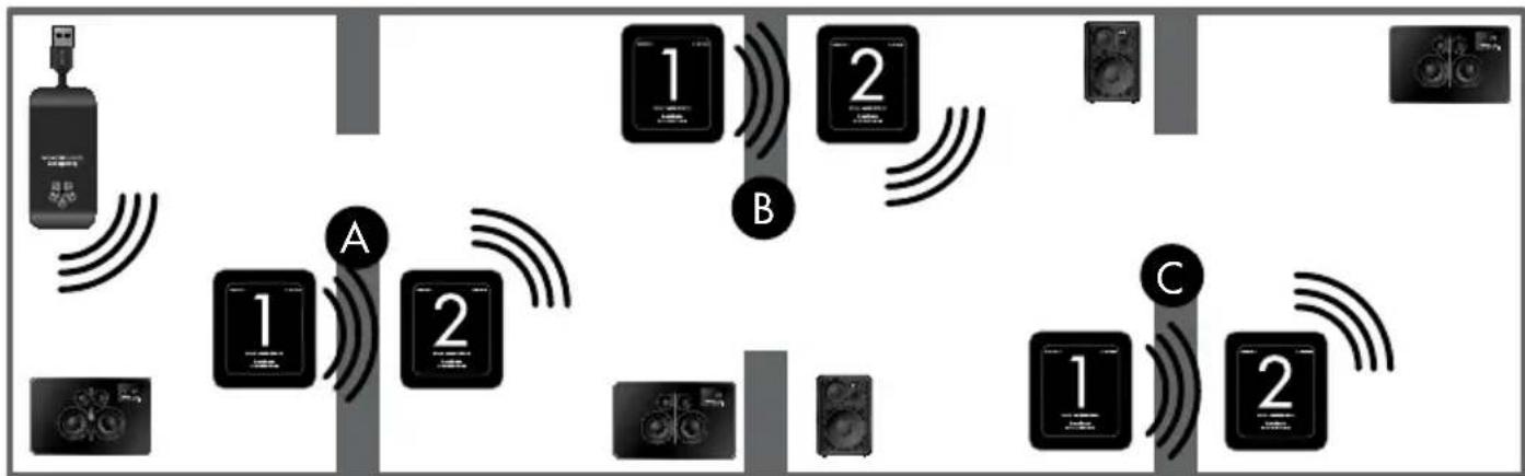
5. EXTENDING NETWORK WITH UP TO THREE WR200 SETS
flowchart
graph TD
    A["Device 1"] -->|Signal| B["Device 2"]
    B -->|Signal| C["Device 3"]
    C -->|Signal| D["Device 4"]
    D -->|Signal| E["Device 5"]
    E -->|Signal| F["Device 6"]
    F -->|Signal| G["Device 7"]
    G -->|Signal| H["Device 8"]
    H -->|Signal| I["Device 9"]
    I -->|Signal| J["Device 10"]
    J -->|Signal| K["Device 11"]
    K -->|Signal| L["Device 12"]
    L -->|Signal| M["Device 13"]
    M -->|Signal| N["Device 14"]
    N -->|Signal| O["Device 15"]
    O -->|Signal| P["Device 16"]
    P -->|Signal| Q["Device 17"]
    Q -->|Signal| R["Device 18"]
    R -->|Signal| S["Device 19"]
    S -->|Signal| T["Device 20"]
    T -->|Signal| U["Device 21"]
    U -->|Signal| V["Device 22"]
    V -->|Signal| W["Device 23"]
    W -->|Signal| X["Device 24"]
    X -->|Signal| Y["Device 25"]
    Y -->|Signal| Z["Device 26"]
    Z -->|Signal| AA["Device 27"]
    AA -->|Signal| AB["Device 28"]
    AB -->|Signal| AC["Device 29"]
    AC -->|Signal| AD["Device 30"]
If using more than one WR200 set, use different extender channels (X, Z and Y) for all sets. Change the house code accordingly;
Set A: receive house code 1, send house code 2.
Set B: receive house code 2, send house code 3.
Set C: receive house code 3, send house code 1.
CONNECT DEVICE DIRECTLY BY CABLE TO WR200
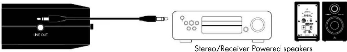
text_image
LINE OUT Stereo/Receiver Powered speakersThere is a line output on both unit 1 and 2. With this feature you can connect a stereo/receiver or powered speakers directly to the WR200 via a cable. The devices will then play wireless audio at the same time as your wireless Living speakers.
Note: You can connect any device with line input.
The lightning flash with arrowhead symbol, within an equilateral triangle, is intended to alert the user to the presence of uninsulated "dangerous voltage" within the product's enclosure that may be of sufficient magnitude to constitute a risk of electric shock to persons.

The exclamation point within an equilateral triangle is intended to alert the user to the presence of important operating and maintenance (servicing) instructions in the literature accompanying the appliance.
WARNING:
TO REDUCE THE RISK OF FIRE OR ELECTRIC SHOCK, DO NOT EXPOSE THIS APPARATUS TO RAIN OR MOISTURE.
CAUTION:
TO REDUCE THE RISK OF ELECTRIC SHOCK, DO NOT REMOVE COVER (OR BACK). NO USER-SERVICEABLE PARTS INSIDE. REFER SERVICING TO QUALIFIED SERVICE PERSONNEL.
IMPORTANT SAFETY INSTRUCTIONS
- Read these instructions.
- Keep these instructions.
- Heed all warnings.
- Follow all instructions.
- Do not use this apparatus near water.
-
Clean only with dry cloth.
-
Do not block any ventilation openings. Install in accordance with the manufacturer's instructions.
-
Do not install near any heat sources such as radiators, heat registers, stoves, or other apparatus (including amplifiers) that produce heat.
-
Protect the power cord from being walked on or pinched particularly at plugs, convenience receptacles, and the point where they exit from the apparatus.
-
Only use attachments/accessories specified by the manufacturer.
-
Unplug this apparatus during lightning storms or when unused for long periods of time.
-
Refer all servicing to qualified service personnel. Servicing is required when the apparatus has been damaged in any way, such as power-supply cord or plug is damaged, liquid has been spilled or objects have fallen into the apparatus, the apparatus has been exposed to rain or moisture, does not operate normally, or has been dropped.
-
Damage Requiring Service Unplug the apparatus from the wall outlet and refer servicing to qualified service personnel under thee following conditions:
A. When the power-supply cord or plug is damaged, B. If liquid has been spilled, or objects have fallen into the apparatus,
C. If the apparatus has been exposed to rain or water,
D. If the apparatus does not operate normally by following the operating instructions. Adjust only those controls that are covered by the operating instructions as an improper adjustment of other controls may result in damage and will often require extensive work by a qualified technician to restore the apparatus to its normal operation, E. If the apparatus has been dropped or damaged in any way, and F. When the apparatus exhibits a distinct change in performance this indicates a need for service.
14. Object and Liquid Entry
Never push objects of any kind into the apparatus through openings as they may touch dangerous voltage points or short-out parts that could result in a fire or electric shock. The apparatus shall not be exposed to dripping or splashing and no objects filled with liquids, such as vases shall be placed on the apparatus. Don't put candles or other burning objects on top of this unit.
15. Batteries
Always consider the environmental issues and follow local regulations when disposing of batteries.
-
If you install the apparatus in a built-in installation, such as a bookcase or rack, ensure that there is adequate ventilation. Leave 20 cm (8") of free space at the top and sides and 10 cm (4") at the rear. The rear edge of the shelf or board above the apparatus shall be set 10 cm (4") away from the rear panel or wall, creating a flue-like gap for warm air to escape.
-
The power supply and power cord for this apparatus is intended for indoor use only.
-
Only use the enclosed AC adaptor.