
3CRWE554G72T OfficeConnect - Router 3COM - Free user manual and instructions
Find the device manual for free 3CRWE554G72T OfficeConnect 3COM in PDF.


| Product Type | Wireless Router |
| Brand | 3Com |
| Model | 3CRWE554G72T OfficeConnect |
| Wireless Standard | IEEE 802.11g |
| Frequency Band | 2.4 GHz |
| Data Transfer Rate | Up to 54 Mbps |
| LAN Ports | 4 x 10/100 Ethernet |
| WAN Port | 1 x 10/100 Ethernet |
| Antenna | 2 external dipole antennas |
| Security | WEP, WPA, WPA2 |
| Firewall | NAT, SPI |
| VPN Support | PPTP, IPSec pass-through |
| Dimensions | 7.5 x 5.5 x 1.2 inches (19 x 14 x 3 cm) |
| Weight | 0.5 lbs (227 g) |
| Power Input | 12V DC, 1A |
| Power Consumption | 10W (max) |
| Operating Temperature | 0°C to 40°C |
| Storage Temperature | -20°C to 70°C |
| Humidity | 10% to 90% non-condensing |
| Certification | FCC, CE |
| Package Contents | Router, power adapter, Ethernet cable, quick start guide, CD with manual |
| Warranty | Limited lifetime |
Frequently Asked Questions - 3CRWE554G72T OfficeConnect 3COM
User questions about 3CRWE554G72T OfficeConnect 3COM
0 question about this device. Answer the ones you know or ask your own.
Ask a new question about this device
Download the instructions for your Router in PDF format for free! Find your manual 3CRWE554G72T OfficeConnect - 3COM and take your electronic device back in hand. On this page are published all the documents necessary for the use of your device. 3CRWE554G72T OfficeConnect by 3COM.
USER MANUAL 3CRWE554G72T OfficeConnect 3COM
Wireless 11g Cable/DSL Router User Guide
3CRWE554G72T
3CRWE554G72TU

The Standard for Wireless Fidelity.
http://www.3com.com/
Part No. DUA0554-TAAA02
Published November 2004

natural_image
Abstract black ink brushstroke design on white background (no text or symbols)3Com Corporation 350 Campus Drive Marlborough, MA USA 01752-3064
Copyright © 2004, 3Com Corporation. All rights reserved. No part of this documentation may be reproduced in any form or by any means or used to make any derivative work (such as translation, transformation, or adaptation) without written permission from 3Com Corporation.
3Com Corporation reserves the right to revise this documentation and to make changes in content from time to time without obligation on the part of 3Com Corporation to provide notification of such revision or change.
3Com Corporation provides this documentation without warranty, term, or condition of any kind, either implied or expressed, including, but not limited to, the implied warranties, terms or conditions of merchantability, satis34factory quality, and fitness for a particular purpose. 3Com may make improvements or changes in the product(s) and/or the program(s) described in this documentation at any time.
If there is any software on removable media described in this documentation, it is furnished under a license agreement included with the product as a separate document, in the hard copy documentation, or on the removable media in a directory file named LICENSE.TXT or ILICENSE.TXT. If you are unable to locate a copy, please contact 3Com and a copy will be provided to you.
UNITED STATES GOVERNMENT LEGEND
If you are a United States government agency, then this documentation and the software described herein are provided to you subject to the following:
All technical data and computer software are commercial in nature and developed solely at private expense. Software is delivered as "Commercial Computer Software" as defined in DFARS 252.227-7014 (June 1995) or as a "commercial item" as defined in FAR 2.101(a) and as such is provided with only such rights as are provided in 3Com's standard commercial license for the Software. Technical data is provided with limited rights only as provided in DFAR 252.227-7015 (Nov 1995) or FAR 52.227-14 (June 1987), whichever is applicable. You agree not to remove or deface any portion of any legend provided on any licensed program or documentation contained in, or delivered to you in conjunction with, this User Guide.
Unless otherwise indicated, 3Com registered trademarks are registered in the United States and may or may not be registered in other countries.
3Com, OfficeConnect and the 3Com logo are registered trademarks of 3Com Corporation.
Intel and Pentium are registered trademarks of Intel Corporation. Microsoft, MS-DOS, Windows, and Windows NT are registered trademarks of Microsoft Corporation. Novell and NetWare are registered trademarks of Novell, Inc. UNIX is a registered trademark in the United States and other countries, licensed exclusively through X/Open Company, Ltd.
Netscape Navigator is a registered trademark of Netscape Communications.
JavaScript is a trademark of Sun Microsystems
Wi-Fi and the Wi-Fi logo are registered trademarks of the WI-Fi Alliance.
IEEE and 802 are trademarks of the Institute of Electrical and Electronics Engineers, Inc.
All other company and product names may be trademarks of the respective companies with which they are associated.
ENVIRONMENTAL STATEMENT
It is the policy of 3Com Corporation to be environmentally-friendly in all operations. To uphold our policy, we are committed to:
Establishing environmental performance standards that comply with national legislation and regulations.
Conserving energy, materials and natural resources in all operations.
Reducing the waste generated by all operations. Ensuring that all waste conforms to recognized environmental standards. Maximizing the recyclable and reusable content of all products.
Ensuring that all products can be recycled, reused and disposed of safely.
Ensuring that all products are labelled according to recognized environmental standards.
Improving our environmental record on a continual basis.
End of Life Statement
3Com processes allow for the recovery, reclamation and safe disposal of all end-of-life electronic components.
Regulated Materials Statement
3Com products do not contain any hazardous or ozone-depleting material.
Environmental Statement about the Documentation
The documentation for this product is printed on paper that comes from sustainable, managed forests; it is fully biodegradable and recyclable, and is completely chlorine-free. The varnish is environmentally-friendly, and the inks are vegetable-based with a low heavy-metal content.
CONTENTS
ABOUT THIS GUIDE
Naming Convention 7
Conventions 8
Feedback about this User Guide 8
Related Documentation 9
1 INTRODUCING THE ROUTER
OfficeConnect Wireless 11g Cable/DSL Router 11
Router Advantages 13
Package Contents 13
Minimum System and Component Requirements 14
Front Panel 14
Rear Panel 16
2 HARDWARE INSTALLATION
Introduction 19
Safety Information 19
Positioning the Router 19
Using the Rubber Feet 20
Stacking the Router 20
Wall Mounting 20
Before you Install your Router 21
Powering Up the Router 22
Connecting the Router 22
3 SETTING UP YOUR COMPUTERS
Obtaining an IP Address Automatically 25
Windows 2000 25
Windows XP 27
Windows 95/98/ME 27
Macintosh 27
Disabling PPPoE and PPTP Client Software 28
Disabling Web Proxy 28
4 RUNNING THE SETUP WIZARD
Accessing the Wizard 29
Password 32
Time Zone 33
WAN Settings 33
LAN Settings 40
DHCP 40
Wireless Settings 41
Summary 42
5 ROUTER CONFIGURATION
Navigating Through the Router Configuration Pages 45
Main Menu 45
Option Tabs 46
Welcome Screen 46
Notice Board 46
Password 47
Wizard 48
LAN Settings 48
Unit Configuration 48
DHCP Clients List 49
Wireless Settings 51
Configuration 52
Encryption 54
Configuring WPA Encryption 54
Configuring WEP Encryption 57
Connection Control 60
Client List 62
WDS 63
Profile 64
Internet Settings 65
Connection to ISP 66
Firewall 73
Virtual Servers 73
Special Applications 75
PC Privileges 77
URL Filter 80
Content Filter 83
SPI 84
System Tools 87
Restart 88
Time Zone 88
Configuration 89
Upgrade 90
Advanced 91
Static Route 91
RIP 92
Routing Table 94
DDNS 94
Security 96
Status and Logs 98
Status 98
Usage 99
Logs 100
Support/Feedback 100
Support 100
Feedback 101
6 TROUBLESHOOTING
Basic Connection Checks 103
Browsing to the Router Configuration Screens 103
Connecting to the Internet 104
Forgotten Password and Reset to Factory Defaults 105
Wireless Networking 105
Replacement Power Adapters 107
Alert LED 108
Recovering from Corrupted Software 108
Frequently Asked Questions 109
A USING DISCOVERY
Running the Discovery Application 111
Windows Installation (95/98/2000/Me/NT) 111
B IP ADDRESSING
The Internet Protocol Suite 113
Managing the Router over the Network 113
IP Addresses and Subnet Masks 113
How does a Device Obtain an IP Address and Subnet Mask? 115
DHCP Addressing 115
Static Addressing 115
Auto-IP Addressing 115
C TECHNICAL SPECIFICATIONS
D SAFETY INFORMATION
E END USER SOFTWARE LICENSE AGREEMENT
F ISP INFORMATION
GLOSSARY
INDEX
REGULATORY NOTICES FOR THE WIRELESS 11G CABLE/DSL ROUTER
Industry Canada - Class B 143
ABOUT THIS GUIDE
This guide describes how to install and configure the OfficeConnect Wireless 11g Cable/DSL Router (3CRWE554G72T and 3CRWE554G72TU).
This guide is intended for use by those responsible for installing and setting up network equipment; consequently, it assumes a basic working knowledge of LANs (Local Area Networks) and Internet Router systems.

If a release note is shipped with the OfficeConnect Wireless 11g Cable/DSL Router and contains information that differs from the information in this guide, follow the information in the release note.
Most user guides and release notes are available in Adobe Acrobat Reader Portable Document Format (PDF) on the 3Com World Wide Web site:
http://www.3com.com
Naming Convention
Throughout this guide, the OfficeConnect Wireless 11g Cable/DSL Router is referred to as the "Router".
Category 3 and Category 5 Twisted Pair Cables are referred to as Twisted Pair Cables throughout this guide.
Conventions
Table 1 and Table 2 list conventions that are used throughout this guide.
Table 1 Notice Icons
| Icon Notice Type Description | |
 | Information note Information that describes important features or instructions. |
 | Caution Information that alerts you to potential loss of data or potential damage to an application, system, or device. |
 | Warning Information that alerts you to potential personal injury. |
Table 2 Text Conventions
| Convention Description | |
| The words “enter” and “type” | When you see the word “enter” in this guide, you must type something, and then press Return or Enter. Do not press Return or Enter when an instruction simply says “type.” |
| Keyboard key names | If you must press two or more keys simultaneously, the key names are linked with a plus sign (+). Example:Press Ctrl+Alt+Del |
| Words in italics Italics are used to:■ Emphasize a point.■ Denote a new term at the place where it is defined in the text.■ Identify menu names, menu commands, and software button names. Examples:From the Help menu, select Contents.Click OK. | |
Feedback about this User Guide
Your suggestions are very important to us. They will help make our documentation more useful to you. Please e-mail comments about this document to 3Com at:
pddtechpubs\_comments@3com.com
Please include the following information when commenting:
■Document title
■Document part number (on the title page)
■Page number (if appropriate)
Example:
■OfficeConnect Wireless 11g Cable/DSL Router User Guide
■Part Number DUA0554-TAAA02
■Page 24

Do not use this e-mail address for technical support questions. For information about contacting Technical Support, please refer to the Support and Safety Information sheet.
Related Documentation
In addition to this guide, each Router document set includes one Installation Guide. This guide contains the instructions you need to install and configure your Router.
1 INTRODUCING THE ROUTER
Welcome to the world of networking with 3Com®. In the modern business environment, communication and sharing information is crucial. Computer networks have proved to be one of the fastest modes of communication but, until recently, only large businesses could afford the networking advantage. The OfficeConnect® product range from 3Com has changed all this, bringing networks to the small office.
The products that compose the OfficeConnect range give you, the small office user, the same power, flexibility, and protection that has been available only to large corporations. Now, you can network the computers in your office, connect them all to a single Internet outlet, and harness the combined power of all of your computers.
OfficeConnect Wireless 11g Cable/DSL Router
The OfficeConnect Wireless 11g Cable/DSL Router is designed to provide a cost-effective means of sharing a single broadband Internet connection amongst several wired and wireless computers. The Router also provides protection in the form of an electronic “firewall”, preventing anyone outside of your network from seeing your files or damaging your computers. The Router can also prevent your users from accessing Web sites which you find unsuitable.
Figure 1 shows an example network without a Router. In this network, only one computer is connected to the Internet. This computer must always be powered on for the other computers on the network to access the Internet.
Figure 1 Example Network Without a Router
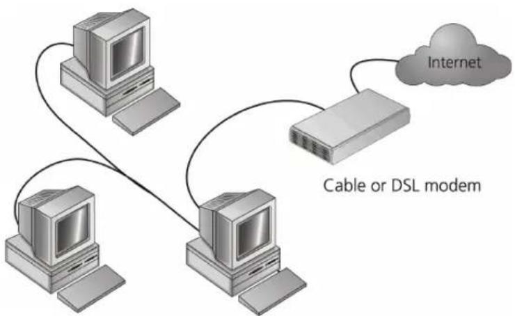
flowchart
graph TD
    A["Desktop Computer"] -->|Cable or DSL modem| B["Server"]
    C["Desktop Computer"] -->|Cable or DSL modem| B
    D["Internet"] -->|Cable or DSL modem| B
When you use the Router in your network (Figure 2), it becomes your connection to the Internet. Connections can be made directly to the Router, or to an OfficeConnect Switch or Hub, expanding the number of computers you can have in your network.
Figure 2 Example Network Using a Wireless 11g Cable/DSL Router

flowchart
graph TD
    A["Computer"] -->|Your existing Cable/DSL Modem| B["Router"]
    B --> C["Internet"]
    B --> D["Wireless users"]
    B --> E["Router"]
    style A fill:#f9f,stroke:#333
    style B fill:#ccf,stroke:#333
    style C fill:#cfc,stroke:#333
    style D fill:#fcc,stroke:#333
    style E fill:#cff,stroke:#333
Router Advantages The advantages of the Router include:
■Shared Internet connection for both wired and wireless computers
■High speed 802.11g wireless networking
■ No need for a dedicated, “always on” computer serving as your Internet connection
■ Cross-platform operation for compatibility with Windows, Unix and Macintosh computers
■Easy-to-use, Web-based setup and configuration
■Provides centralization of all network address settings (DHCP)
■Acts as a Virtual server to enable remote access to Web, FTP, and other services on your network
■ Security — Firewall protection against Internet hacker attacks and encryption to protect wireless network traffic
■Filtered access of inappropriate Web sites using the built-in URL filter
Package Contents The Router kit includes the following items:
■One OfficeConnect Wireless 11g Cable/DSL Router
■One power adapter for use with the Router
■Four rubber feet
■One Ethernet cable
■ One CD-ROM containing the Router Discovery program and this User Guide
■Installation Guide
■One Support and Safety Information Sheet
■One Warranty Flyer
If any of these items are missing or damaged, please contact your retailer.
| Minimum System and Component Requirements | Your Router requires that the computer(s) and components in your network be configured with at least the following:■A computer with an operating system that supports TCP/IP networking protocols (for example Windows 95/98/NT/Me/2000/XP, Unix, Mac OS 8.5 or higher).■An Ethernet 10Mbps or 10/100 Mbps NIC for each computer to be connected to the four-port switch on your Router.■An 802.11b or 802.11g wireless NIC.■A cable modem or DSL modem with an Ethernet port (RJ-45 connector).■An active Internet access account.■A Web browser that supports JavaScript, such as Netscape 4.7 or higher, Internet Explorer 5.0 or higher, or Mozilla 1.2.1 or higher. |
| Front Panel | The front panel of the Router contains a series of indicator lights (LEDs) that help describe the status of various networking and connection operations. |
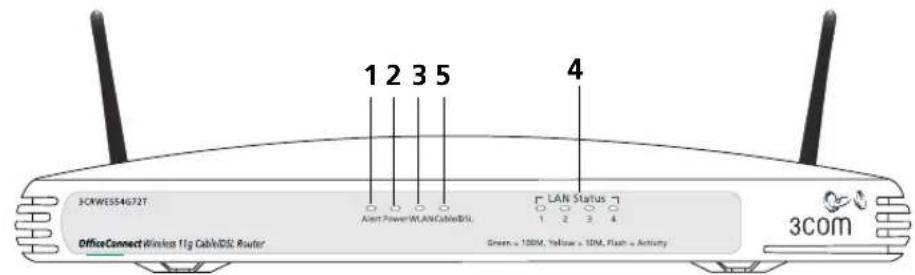
Figure 3 Router - Front Panel
1 Alert LED
Orange
Indicates a number of different conditions, as described below.
Off - The Router is operating normally.
Flashing quickly - Indicates one of the following conditions:
■The Router has just been started up and is running a self-test routine, or
■ The administrator has invoked the Reset to Factory Defaults command, or
■The system software is in the process of being upgraded
In each of these cases, wait until the Router has completed the current operation and the alert LED is Off.
Flashing slowly - The Router has completed the Reset to Factory Defaults process, and is waiting for you to reset the unit. To do this, remove power, wait 10 seconds and then re-apply power. The Router will then enter the start-up sequence and resume normal operation.

If you have used a cable to reset the unit to Factory Defaults, follow steps 5 to 7 in "Forgotten Password and Reset to Factory Defaults" on page 105.
On for 2 seconds, and then off - The Router has detected and prevented a hacker from attacking your network from the Internet.
Continuously on - A fault has been detected with your Router during the start-up process. Refer to Chapter 6 "Troubleshooting".
2 Power LED
Green
Indicates that the Router is powered on.
3 Wireless LAN (WLAN) Status LED
Yellow
If the LED is on it indicates that wireless networking is enabled. If the LED is flashing, data is being transmitted or received. If the LED is off, the Wireless LAN has been disabled in the Router, or there is a problem. Refer to Chapter 6 "Troubleshooting".
4 Four LAN Status LEDs
Green (100 Mbps link) / yellow (10 Mbps link)
If the LED is on, the link between the port and the next piece of network equipment is OK. If the LED is flashing, the link is OK and data is being transmitted or received. If the LED is off, nothing is connected, the connected device is switched off, or there is a problem with the connection (refer to Chapter 6 "Troubleshooting"). The port will automatically adjust to the correct speed and duplex.
5 Cable/DSL Status LED
Green (100 Mbps link) / yellow (10 Mbps link)
If the LED is on, the link between the Router and the cable or DSL modem is OK. If the LED is flashing, the link is OK and data is being transmitted or received. If the LED is off, nothing is connected, the modem is switched off or there is a problem (refer to Chapter 6 "Troubleshooting").
Rear Panel
The rear panel (Figure 4) of the Router contains four LAN ports, one Ethernet Cable/DSL port, a power adapter OK LED, and a power adapter socket.
Figure 4 Router - Rear Panel
6 Wireless Antennae
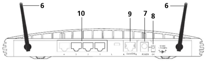
The antennae on the product should be placed in a 'V' position when initially installed.

CAUTION: Do not force the antennae beyond their mechanical stops. Rotating the antennae further may cause damage.
7 Power Adapter Socket
Only use the power adapter supplied with this Router. Do not use any other adapter.
8 Power Adapter OK LED
Green
Indicates that the power adapter is supplying power to the Router. If the LED is off, there may be a problem with the power adapter or adapter cable.
9 Ethernet Cable/DSL port
Use the supplied patch cable to connect the Router to the Ethernet port on your cable or DSL modem. The port will automatically adjust to the
correct speed and duplex, and will set itself to MDI or MDIX depending on the device to which they are connected and the type of cable used.
10 Four 10/100 LAN ports
Using suitable RJ-45 cable, you can connect your Router to a computer, or to any other piece of equipment that has an Ethernet connection (for example, a hub or a switch). The LAN ports will automatically set themselves to MDI or MDIX depending on the device to which they are connected and the type of cable used.
2
HARDWARE INSTALLATION
| Introduction | This chapter will guide you through a basic installation of the Router, including:■Connecting the Router to the Internet.■Connecting the Router to your network.■Setting up your computers for networking with the Router. |
| Safety Information | |
| 4 | WARNING: Please read the "Safety Information" section in Appendix D before you start. |
| 4 | VORSICHT: Bitte lesen Sie den Abschnitt "Wichtige Sicherheitshinweise" sorgfältig durch, bevor Sie das Gerät einschalten. |
| 4 | AVERTISSEMENT: Veuillez lire attentivement la section "Consignes importantes de sécurité" avant de mettre en route. |
| Positioning the Router | You should place the Router in a location that:■ is conveniently located for connection to the cable or DSL modem that will be used to connect to the Internet.■ is centrally located to the wireless computers that will connect to the Router. A suitable location might be on top of a high shelf or similar furniture to optimize wireless connections to computers in both horizontal and vertical directions, allowing wider coverage.■ allows convenient connection to the computers that will be connected to the four LAN ports on the rear panel, if desired.■ allows easy viewing of the front panel LED indicator lights, and access to the rear panel connectors, if necessary. |
When positioning your Router, ensure:
■It is out of direct sunlight and away from sources of heat.
■ Cabling is away from power lines, fluorescent lighting fixtures, and sources of electrical noise such as radios, transmitters and broadband amplifiers.
■Water or moisture cannot enter the case of the unit.
■Air flow around the unit and through the vents in the side of the case is not restricted. 3Com recommends you provide a minimum of 25 mm (1 in.) clearance.
Using the Rubber Feet
Use the four self-adhesive rubber feet to prevent your Router from moving around on your desk or when stacking with other flat top OfficeConnect units. Only stick the feet to the marked areas at each corner of the underside of your Router.
Stacking the Router
If you are stacking your Router with other OfficeConnect units, install the Router at the top of the stack. Refer to the documentation supplied with your other OfficeConnect unit for details on using the stacking clip.

A stacking clip is not supplied with the Router. Use the stacking clip supplied with another stackable OfficeConnect unit.
Wall Mounting
There are two slots on the underside of the Router that can be used for wall mounting.

When wall mounting the unit, ensure that it is within reach of the power outlet.
You will need two suitable screws to wall mount the unit. To do this:
1 Ensure that the wall you use is smooth, flat, dry and sturdy and make two screw holes which are 150 mm (5.9 in.) apart.
2 Fix the screws into the wall, leaving their heads 3 mm (0.12 in.) clear of the wall surface.
3 Remove any connections to the unit and locate it over the screw heads. When in line, gently push the unit on to the wall and move it downwards to secure.

When making connections, be careful not to push the unit up and off the wall.

CAUTION: Only wall mount single units, do not wall mount stacked units.
Before you Install your Router
Before you install and configure your Router, you need the following additional information. If you do not have this information, contact your Internet Service Provider (ISP). Space is provided below for you to record this information.
If you have a DSL connection and your ISP allocates IP information dynamically over PPPoE, you need a User Name and Password:
PPPoE User Name : ____
PPPoE Password : ____
PPPoE Service Name : ____

You only need a PPPoE Service Name if your ISP requires one. Do not enter anything if your ISP does not require this information.
If you have a DSL connection and your ISP allocates IP information dynamically over PPTP, you need a User Name, Password and PPTP Server Address:
PPTP User Name : ____
PPTP Password : ____
PPTP Server Address : ____.____.____
If your ISP allocates fixed or static IP information, you need the following information:
IP Address : ____.____.____
Subnet Mask : ____.____.____
Default Router address : ____.____.____
DNS address : ____.____.____

If your ISP allocates IP information dynamically over a protocol other than PPPoE, you do not need any further information. This configuration is typical of cable connections.
Powering Up the Router
To power up the Router:
1 Plug the power adapter into the power adapter socket located on the back panel of the Router.
2 Plug the power adapter into a standard electrical wall socket.
Connecting the Router
The first step for installing your Router is to physically connect it to a cable or DSL modem and then connect it to a computer in order to be able to access the Internet. See Figure 5:
Figure 5 Connecting the Router
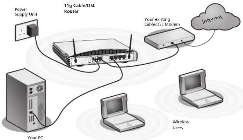
flowchart
graph TD
    A["Power Supply Unit"] --> B["11g Cable/DSL Router"]
    C["Your PC"] --> B
    D["Your existing Cable/DSL Modem"] --> B
    E["Internet"] --> B
    F["Wireless Users"] --> B
To use your Router to connect to the Internet through an external cable or DSL modem:
1 Insert one end of the supplied Ethernet (RJ-45 Category 5) cable into the Cable/DSL port on the rear panel of the Router.
2 Insert the other end of the cable into the RJ-45 port on your cable or DSL modem. Check that the Cable/DSL status LED lights on the Router.
3 Connect the cable or DSL modem to the Internet.
4 Connect your computer to one of the four LAN ports on the Router using a Category 5 twisted pair cable. Check that the corresponding LAN status LED on the Router lights.
You have now completed the hardware installation of your Router. Next you need to set up your computers so that they can make use of the Router to communicate with the Internet.
3Com recommends that you perform the initial Router configuration from a computer that is directly connected to one of the LAN ports.
If you configure the Router from a wireless computer, note that you may lose contact with the Router if you change the wireless configuration.
To communicate wirelessly with your Router, your wireless NIC should be set as follows:
■Encryption — none
■Service Area Name/SSID — 3Com
■Channel — 11
3
SETTING UP YOUR COMPUTERS
The Router has the ability to dynamically allocate network addresses to the computers on your network, using DHCP. However, your computers need to be configured correctly for this to take place. To change the configuration of your computers to allow this, follow the instructions in this chapter. If your computers are configured with fixed or static addresses and you do not wish to change this, then you should use the Discovery program on the Router CD-ROM to detect and configure your Router. Refer to Appendix A for information on using the Discovery program.
Obtaining an IP Address Automatically
Refer to the section below which relates to your operating system for details on how to obtain an IP address automatically.
Windows 2000 If you are using a Windows 2000-based computer, use the following procedure to change your TCP/IP settings:
1 From the Windows Start Menu, select Settings > Control Panel.
2 Double click on Network and Dial-Up Connections.
3 Double click on Local Area Connection.
4 Click on Properties.
5 A screen similar to Figure 6 should be displayed. Select Internet Protocol TCP/IP and click on Properties.
Figure 6 Local Area Properties Screen
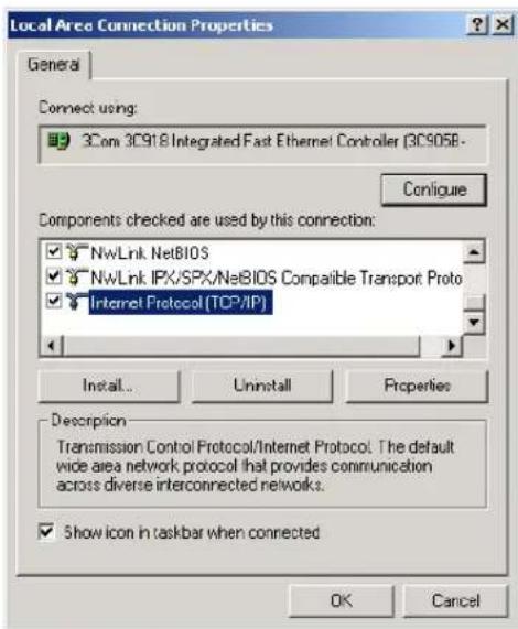
6 Ensure that the options Obtain an IP Address automatically, and Obtain DNS server address automatically are both selected as shown in Figure 7. Click OK.
Figure 7 Internet Protocol (TCP/IP) Properties Screen
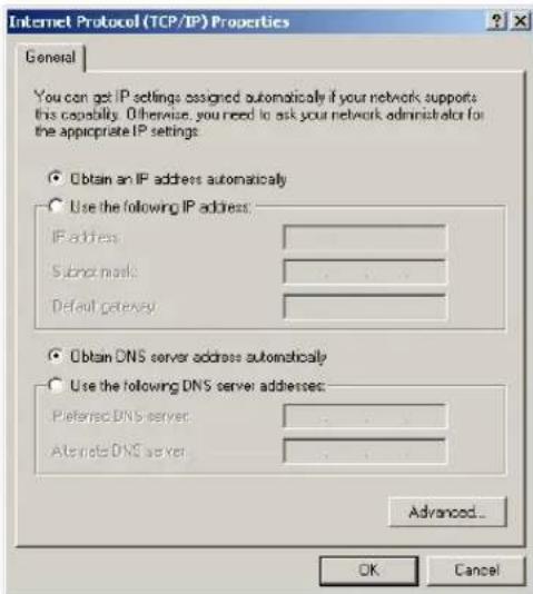
7 Restart your computer.
Windows XP If you are using a Windows XP computer, use the following procedure to change your TCP/IP settings:
1 From the Windows Start menu, select Control Panel.
2 Click on Network and Internet Connections.
3 Click on the Network Connections icon.
4 Double click on LAN or High Speed Connection icon. A screen titled Local Area Connection Status will appear.
5 Select Internet Protocol TCP/IP and click on Properties.
6 Ensure that the options Obtain an IP Address automatically, and Obtain DNS servers automatically are both selected. Click OK.
7 Restart your computer.
Windows 95/98/ME If you are using a Windows 95/98/ME computer, use the following procedure to change your TCP/IP settings:
1 From the Windows Start Menu, select Settings > Control Panel.
2 Double click on Network. Select the TCP/IP item for your network card and click on Properties.
3 In the TCP/IP dialog, select the IP Address tab, and ensure that Obtain IP address automatically is selected. Click OK.
Macintosh If you are using a Macintosh computer, use the following procedure to change your TCP/IP settings:
1 From the desktop, select Apple Menu, Control Panels, and TCP/IP.
2 In the TCP/IP control panel, set Connect Via: to "Ethernet".
3 In the TCP/IP control panel, set Configure: to "Using DHCP Server."
4 Close the TCP/IP dialog box, and save your changes.
5 Restart your computer.
Disabling PPPoE and PPTP Client Software
If you have PPPoE or PPTP client software installed on your computer, you will need to disable it. To do this:
1 From the Windows Start menu, select Settings > Control Panel.
2 Double click on Internet Options.
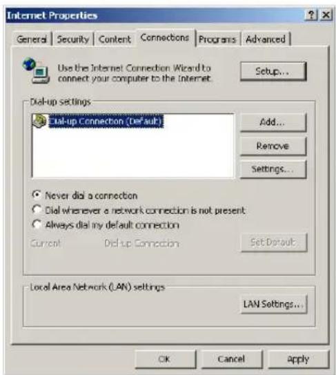
3 Select the Connections Tab. A screen similar to Figure 8 should be displayed.
4 Select the Never Dial a Connection option.
Figure 8 Internet Properties Screen

You may wish to remove the PPPoE client software from your computer to free resources, as it is not required for use with the Router.
Disabling Web Proxy
Ensure that you do not have a web proxy enabled on your computer.
Go to the Control Panel and click on Internet Options. Select the Connections tab and click LAN Settings at the bottom. Make sure that the Use Proxy Server option is unchecked.
4
RUNNING THE SETUP WIZARD
Accessing the Wizard
The Router setup program is Web-based, which means that it is accessed through your Web browser (Netscape Navigator 4.7 or higher, Internet Explorer 5.0 or higher, or Mozilla 1.2.1 or higher).
To use the Setup Wizard:
1 Ensure that you have at least one computer connected to the Router. Refer to Chapter 2 for details on how to do this.
2 Launch your Web browser on the computer.
3 Enter the following URL in the location or address field of your browser: http://192.168.1.1 (Figure 9). The Login screen displays.
Figure 9 Web Browser Location Field (Factory Default)

4 To log in as an administrator, enter the password (the default setting is admin) in the System Password field and click Log in (Figure 10).
Figure 10 Router Login Screen

5 If the password is correct, the Country Selection screen will appear. Select the country you wish to configure the Router for, then click Apply. (Figure 11)

If your purchased your Router in the United States, you do not see this screen, as it is automatically set.
Figure 11 Country Selection Screen

6 When you have selected a country either:
■ The Welcome screen will appear (Figure 12). Select the Wizard tab and click Wizard.
or
■If your Router has not been configured before, the Wizard will launch automatically (refer to Figure 13).
7 Click Next.
8 You will be guided step by step through a basic setup procedure.
Figure 12 Welcome Screen
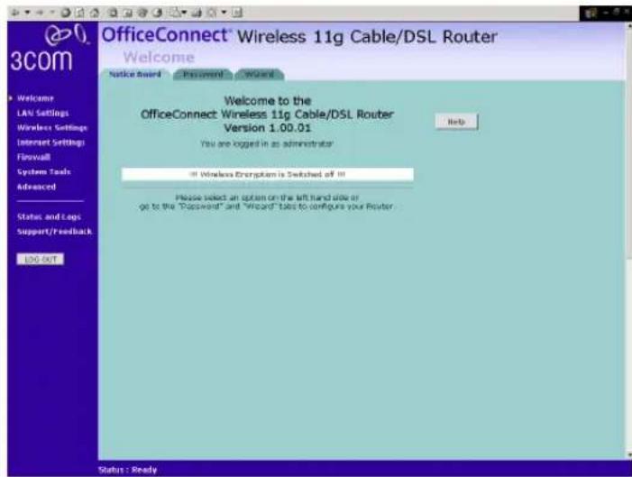
Figure 13 Wizard Screen

Password Figure 14 Change Administration Password Screen

When the Change Administration Password screen (Figure 14) appears, type the Old Password, then a new password in both the New Password and Confirm Password boxes.

3Com recommends entering a new password when setting up the Router for the first time. The Router is shipped from the factory with a default password, admin.
-
Password is case sensitive.
-
Write the new password down and keep it in a safe place, so that you can change your settings in the future.
Click Next to display the Time Zone setup screen (Figure 15).
Time Zone Figure 15 Time Zone Screen
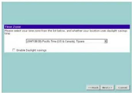
Select your time zone from the pull-down menu, check the daylight savings option if required, and then click Next.

The Daylight Savings option advances the system clock by one hour. It does not cause the system clock to be updated for daylight savings time automatically.
WAN Settings Figure 16 Internet Settings Screen
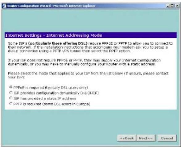
This Internet Addressing Mode window allows you to set up the Router for the type of Internet connection you have. Before setting up your
Internet connection mode, have the modem setting information from your ISP ready.
Select an Internet Addressing mode from the following:
■ PPPoE is required (typically DSL users only) see page 34
■ ISP provides configuration dynamically (via DHCP) see page 35
■ ISP has provided a static IP address see page 36
■ PPTP is required (some DSL users in Europe) see page 37
■ L2TP is required (some DSL users in Europe) see page 39
and click Next.

For further information on selecting a mode see "Internet Settings" on page 65.
PPPoE Mode
Figure 17 PPPoE Screen

To setup the Router for use with a PPP over Ethernet (PPPoE) connection, use the following procedure:
1 Enter your PPP over Ethernet user name in the PPPoE User Name text box.
2 Enter your PPP over Ethernet password in the PPPoE Password text box.
3 Enter your PPP over Ethernet service name in the PPPoE Service Name text box.

Do not enter anything in this box if your ISP does not require a service name.
4 Enter the MTU value supplied by your ISP in the MTU text box. If your ISP has not supplied an MTU value, leave this at the default value. The default is 1454.
5 Select an idle time from the Maximum Idle Time drop down list. This is the amount of time without Internet activity that you want to allow before the Router ends the PPPoE session.
6 Check all of your settings, and then click Next. Refer to "LAN Settings" on page 40 for more information.
Dynamic IP Address Mode
To setup the Router for use with a dynamic IP address connection:
1 Select the ISP provides configuration dynamically (via DHCP) and then click Next. See Figure 16.
Figure 18 Hostname Screen
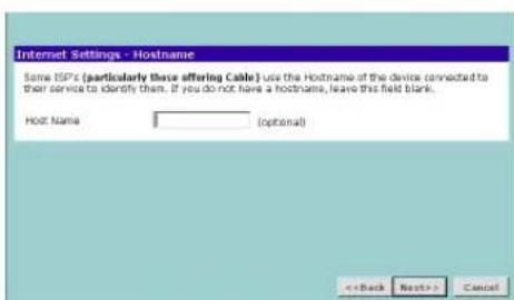
2 Some ISPs require a host name. If your ISP has this requirement, enter the host name in the Host Name text box (Figure 18) and click Next. The Clone MAC Address screen displays.
Figure 19 Clone MAC Address Screen
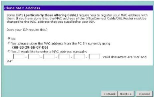
3 If your ISP requires an assigned MAC address, select Yes, I would like to enter a MAC address manually and enter the values for a MAC address if required (Figure 19). If the computer you are now using is the one that was previously connected directly to the cable modem, choose Yes, please clone the MAC address from the PC I'm currently using.
Static IP Mode
To setup the Router for use with a static IP address connection, use the following procedure:
1 Select ISP has provided a static IP address, (see Figure 16) and then click Next. Figure 20 displays.
Figure 20 Static IP Mode Screen

2 Enter your IP Address in the IP Address text box.
3 Enter your subnet mask in the Subnet Mask text box.
4 Enter your ISP Router address in the Internet (ISP) Gateway Address text box.
5 Enter your primary DNS address in the Primary DNS Address text box.
6 Enter your secondary DNS address in the Secondary DNS Address text box.
This step is optional. Not all ISPs require a secondary DNS address.
7 Check all of your settings, and then click Next.
PPTP Mode
Figure 21 PPTP Mode Screen
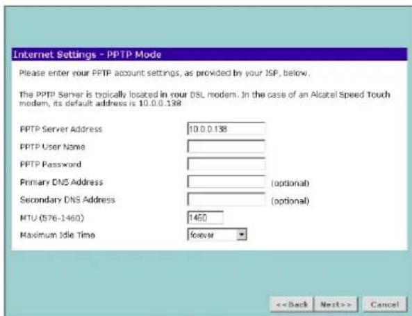
To setup the Router for use with a PPTP connection, use the following procedure:
1 Enter your PPTP server address in the PPTP Server Address text box.
2 Enter your PPTP user name in the PPTP User Name text box.
3 Enter your PPTP password in the PPTP Password text box.
4 Enter your Primary DNS Address and Secondary DNS address.
Your ISP may provide you with primary and secondary DNS addresses. If they have been provided, enter the addresses in the appropriate text boxes. If not, leave 0.0.0.0 in the boxes.
5 Enter the value supplied by your ISP in the MTU text box. If your ISP has not supplied an MTU value, leave this at the default value. The default is 1460.
6 Select an idle time from the Maximum Idle Time drop-down list. This is the amount of time without Internet activity that you want to allow before the Router ends the PPTP session.
7 Check all of your settings, and then click Next. Figure 22 displays.
Figure 22 PPTP IP Settings

8 IP settings must be used when establishing a PPTP connection. Fill in the Initial IP Address and the Initial Subnet Mask fields if your ISP has provided you with these settings. Alternatively, if the PPTP server is located in your DSL modem, click Suggest to select an IP address on the same subnet as the PPTP server.
L2TP Mode
Figure 23 L2TP Mode Screen

To set up the Router for use with an L2TP connection, use the following procedure:
1 Enter your L2TP server address in the L2TP Server Address text box.
2 Enter your L2TP user name in the L2TP User Name text box.
3 Enter your L2TP password in the L2TP Password text box.
4 Enter your Primary DNS Address and Secondary DNS address.
Your ISP may provide you with primary and secondary DNS addresses. they have been provided, enter the addresses in the appropriate text boxes. If not, leave 0.0.0.0 in the boxes.
5 Enter the value supplied by your ISP in the MTU text box. If your ISP has not supplied an MTU value, leave this at the default value. The default is 1440.
6 Select an idle time from the Maximum Idle Time drop-down list. This is the amount of time without Internet activity that you want to allow before the Router ends the L2TP session.
LAN Settings Figure 24 LAN IP Address Screen

This screen displays a suggested LAN IP address and subnet mask of the Router. It also allows you to change the IP address and subnet mask.
DHCP The Router contains a Dynamic Host Configuration (DHCP) server that can automatically configure the TCP/IP settings of every computer on your network.
Figure 25 DHCP Server Setup Screen
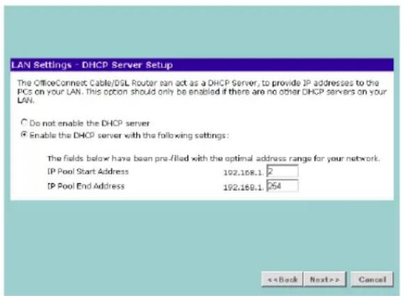
To activate the DHCP Server option, select Enable the DHCP server with the following settings: and specify the IP pool range. The largest available continuous IP pool will be automatically entered; if this is not appropriate, make your required changes. To disable DHCP, select Do not enable the DHCP server. Click Next when you have finished.
Wireless Settings
Figure 26 Wireless Configuration Screen
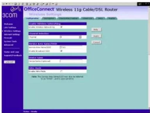
This screen displays the Channel and Service Area Name. It also allows you to change these settings. There are a maximum of 14 channels, the number available to you is dependent on the country you reside in. Selecting Clear Channel Select from the Channel drop-down list allows the Router to automatically select an available channel when first powered on.
The Service Area Name default for 3Com products is "3Com". Up to 32 (case sensitive) characters can be entered for the Service Area Name.
3Com strongly recommends that you change the SSID to something other than the default.
Click Next when you have finished.

If you are configuring the Router from a wireless computer any changes you make to the wireless configuration will result in communication between the Router and your computer being lost. This is why 3Com strongly recommends that you configure the Router from a wired computer.

It is very important that you set up your wireless clients to use the same Service Area Name or SSID as the one you use on this screen. If your clients use a different Service Area Name then they will not be able to communicate with the Router.

The choice of channel is less important as Clients will generally search all of the available channels. You should however make a note of the
channel you select as this may be useful if you experience problems with your clients.
Summary Figure 27 Configuration Summary Screen
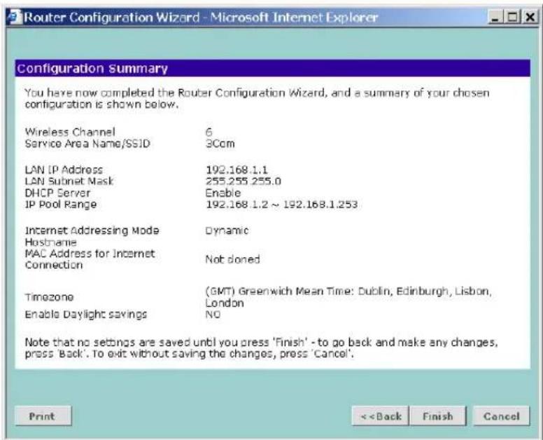
When you complete the Setup Wizard, a configuration summary will display. 3Com recommends that you verify the configuration information of the Router and then print this page for your records. Click Finish to display the Wizard completed screen, shown in Figure 28
Figure 28 Wizard Completed Screen

If you have made changes to the LAN Settings or wireless configuration options, you may need to reconfigure the computer you are using in order to make contact with the Router again.
Your Router is now configured and ready for use.

For information on improving your Wireless network security see "Wireless Settings" on page 51.
See Chapter 5 for a detailed description of the Router configuration screens.
5
This chapter describes all the screens available through the Router configuration pages, and is provided as a reference. To get to the configuration pages, browse to the Router by entering the URL in the location bar of your browser. The default URL is http://192.168.1.1 but if you changed the Router LAN IP address during initial configuration, use the new IP address instead. When you have browsed to the Router, log in using your system password (default admin).
Main Menu
At the left side of all screens is a main menu, as shown in Figure 29 on page 46. When you click on a topic from the main menu, that page will appear in the main part of the screen.
■ Welcome — displays the firmware version of the Router, allows you to change your password, and launch the Wizard
■LAN Settings — allows you to configure IP address and subnet mask information, set up DHCP server parameters, and display the DHCP client list.
■ Wireless Settings — enables /disables access from wireless computers, configures WPA or WEP encryption, and provides facilities for improving the security of the wireless network.
■Internet Settings — sets up Internet addressing modes such as PPPoE and PPTP connections, allows you to clone the Router's MAC address, and set up dynamic IP address allocation and static IP address settings.
■Firewall — allows configuration of the Router's firewall features: Virtual Servers, Special Applications, PCs Privileges, URL Filtering, Content Filtering and SPI options
■System Tools — allows the administrator to perform maintenance activities on the Router.
■Advanced — allows you to monitor and configure the Router's advanced features, including RIP, DDNS and Security.
■Status and Logs — displays the current status and activity logs of the Router.
■ Support/Feedback — contains a comprehensive online help system and allows you to provide 3Com with feedback on your Router.
Option Tabs Each corresponding menu page may also provide sub-sections which are accessed through the use of tabs (see Figure 29 for example). To access a sub-section, simply click on the required tab.
Getting Help
On every screen, a Help button is available which provides access to the context-sensitive online help system. Click Help for further assistance and guidance relating to the current screen.
Welcome Screen
The Welcome section allows you to view the Notice board and to change your Password. You can also gain access to the Configuration Wizard. (See "Accessing the Wizard" on page 29 for details).
Notice Board
Figure 29 Notice Board Screen

The Notice Board is used to display configuration warning messages. For example, you would be warned if you had disabled wireless networking or wireless encryption.
Password
Figure 30 Password Screen

Changing the Administration Password
You can change the password to prevent unauthorized access to the Administration System. To do this:
1 Enter the current password in the Old Password field
2 Enter the new password in the New Password field
3 Enter the new password again in the Confirm Password field
4 Click Apply to save the new password

The password is case sensitive.

If you have forgotten your password you need to reset the Router. See "Forgotten Password and Reset to Factory Defaults" on page 105
Wizard Figure 31 Wizard Screen

Click WIZARD... to launch the configuration wizard. Refer to Chapter 4 for information on how to run the wizard.
LAN Settings The LAN Settings menu provides the following options:
Unit Configuration Figure 32 Unit Configuration Screen

The LAN Settings screen is used to specify the LAN IP address of your Router, and to configure the DHCP server.
1 Select Unit Configuration and then specify the Router IP Address and Subnet Mask in the LAN Settings section. The default IP address of the Router is 192.168.1.1.
2 If you want to use the Router as a DHCP Server, check the Enable check box.
3 Clicking Auto Range will automatically choose the largest available range of addresses for your network. Alternatively, you can change the address range by changing the last digit(s) of the IP Pool Start Address, or the IP Pool End Address, or both.
4 If you use 3Com NBX telephones, enter the IP address of the NBX call processor at 3Com NBX Call Processor.
5 Check all of your settings, and then click Apply.

The DHCP server will give out addresses to both wired and wireless clients.
DHCP Clients List
Figure 33 DHCP Clients List Screen

The DHCP Clients List provides details on the devices that have received IP addresses from the Router. The list is only created when the Router is set up as a DHCP server. For each device that is connected to the LAN the following information is displayed:
■IP address — The Internet Protocol (IP) address issued to the client machine.
- Host Name — The client machine's host name, if configured.
■MAC Address — The Media Access Control (MAC) address of the client's network card.
■ Client Type — Whether the client is connected to the Router by wired or wireless connection.
■Fix — This box is checked if the IP address is fixed to the MAC address of the client's network card. Clients that have fixed addresses will get the same IP address each time they connect.
Check the box to fix an association. Clear the check box to remove the fixed association.
As you connect more devices, the client list will grow to a maximum number of 253 clients.
The release button allows the lease time for the IP address that has been issued to a device to be cleared. The lease time is set at 12 hours. If a PC has been switched off, using the Release button would allow the 12 hour lease time to be cleared. The IP address would then be available for another device if there were no other IP addresses available.
Adding Fixed DHCP Mappings
You can add Fixed Mappings so that the Router allocates an IP address chosen by you when it encounters a particular device.
Click New to display the DHCP Fixed Mapping Setup screen, as shown in Figure 34
Figure 34 DHCP Fixed Mapping Setup Screen
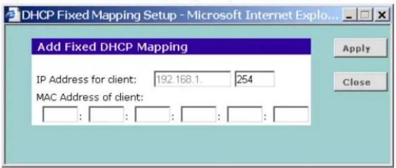

You only need to create Fixed Mappings for devices that need a specific IP address. For devices that do not need a specific IP address, the Router will automatically allocate addresses.
1 Enter the IP Address that you want to reserve in the IP Address for client box.
2 Enter the MAC Address for which you want to create a Fixed Mapping in the MAC Address of client box.

The MAC Address must be entered as 6 hexadecimal pairs, for example 12-34-56-78-90-ab.
3 Click Apply to add the Fixed Mapping, or Close to close the window without adding the Fixed Mapping.
The Fixed DHCP Mapping will be displayed in the DHCP Clients list as a Fixed Association.
Wireless Settings
The Wireless Settings menu provides options described in the following sections.

To improve the security of your wireless network, 3Com recommends that you:
- Change the SSID from its default value - see page 53
- Enable Encryption - see page 54
- Enable Connection Control - see page 60
Configuration
Figure 35 Configuration Screen

Enable Wireless Networking
Use this check box to enable or disable the wireless section of your LAN. When disabled, no wireless PCs can gain access to either the Internet or other PCs on your Wired or Wireless LAN through this Router.
Channel Selection
Select a number from the drop-down list to specify which Channel the Router will transmit and receive on. If another access point or Router nearby is using the same Channel as you, there will be a reduction in the performance of your network. If this seems to be the case, you should select a different channel number. Usually the Wireless computers will scan to find the correct channel, but if they don't you must configure them to use the same Channel number as the Router.
Choose the Clear Channel Select option to automatically choose the clearest channel. The Router will check for the clearest channel whenever it is rebooted, powered up, and when the Clear Channel Select option is first applied.

Valid channels are country dependent. See "Channels" on page 139 for a list of channels approved by each country.
Service Area Name/SSID
This allows you to name your Wireless network. The Service Area Name/SSID field will accept any alphanumeric string and has a maximum length of 32 characters. Your Wireless computers must be configured with exactly the same name or you will not establish a connection. The Service Area Name may also be referred to as "ESSID" depending on your networking vendor. By default the Router uses the name "3Com". 3Com recommends that you change the default name.

In order that your wireless computers can connect to the Router, you must:
■Use Infrastructure Mode, not Ad hoc Mode.
■Have the same Service Area Name as the Router.
■Have the same Channel number as the Router.
■Use the same encryption type and keys as the Router.
■Ensure that the PC is included in the authorized Wireless PCs list if Connection Control is enabled. See page 60.
Enable Broadcast SSID
Disable this feature after you have installed your wireless network to improve the security of your network. When the check box is checked, the Router will broadcast the Service Area Name/SSID of your wireless network, which reduces the security of your Router as it allows any wireless client to see your wireless LAN.
If you have a wireless client that can detect all the available SSIDs in your area, your client will not list the Router SSID unless this feature is enabled. The clients will still be able to connect, provided that they are supplied with the SSID.
3Com recommends that you install your wireless network with this feature enabled and then disable it once you have set up the Router and wireless clients.
Device Name
If required, enter a name that you want to use to uniquely identify the device at the Device Name prompt.
Nitro Mode
The presence of an 11b device in your network can adversely affect the performance of an 11g device, such as the Router. Nitro Mode ensures that the effects of an 11b device are minimized. 3Com recommends that you enable Nitro Mode if you have one or more 11b devices in your network. Check the Enable Nitro Mode check box to activate Nitro Mode.
The client machines must also support Nitro Mode for this feature to work.
Encryption When setting up wireless networks, it is important to remember that with encryption disabled, anyone with a Wireless PC can eavesdrop on your network. 3Com recommends that you get the network working with encryption disabled first and then enable it as the last step. This will simplify setting up your network.
The Router supports two types of encryption:
■WPA — Wi-Fi Protected Access (WPA) is a 256 bit encryption method with keys that change over time.
■WEP — Wireless Equivalent Privacy (WEP) is a 64 bit or 128 bit encryption method with user configurable fixed keys.

WPA provides a higher level of security, provided by its longer key and dynamic changes made to the key over time. 3Com recommends that you use WPA with any clients which support it.

If you enable encryption on the Router, you must reconfigure your wireless PCs to use exactly the same Encryption Type and Keys otherwise the devices will not understand each other.

The encryption methods used by the Router secure data transmitted through wireless communications between the Router and its wireless clients. Enabling encryption has no security effect on data transmitted through wired (Ethernet) connections or through your connections to the Internet.
Configuring WPA Encryption
The only configuration that is needed for WPA is to set up an authentication method. You can choose to use a RADIUS server to authenticate clients, or you can specify a pre-shared key.
The pre-shared key is used to start the dialog between the Router and the client. During this dialog, a new key is agreed, making it more difficult to eavesdrop on wireless networks encrypted using WPA, than those encrypted using WEP.
■To use a RADIUS Server to authenticate each user before they join the network, refer to "Using Enterprise Mode" on page 55.
■To set up the pre-shared key manually as a 256-bit series of hexadecimal digits, refer to "Using Manual Pre-Shared Key" on page 56.
■To set up the pre-shared key manually as a pass-phrase, refer to "Using Pre-Shared Passphrase". on page 57.
Using Enterprise Mode
Figure 36 WPA Encryption Screen - Enterprise Mode
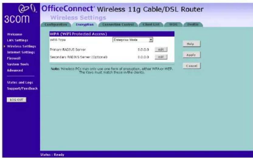
To set up Enterprise Mode as the WPA Type:
1 Select Enterprise Mode from the WPA Type drop-down box. The screen shown in Figure 36 displays.
2 Select the edit button next to Primary RADIUS Server. The RADIUS Server Settings pop-up window opens.
3 Enter the RADIUS Server IP address.
4. Enter the Server Port. The default is 1812.
5 Enter a Secret value.
6 Select the Modify button to save the changes and return to the Encryption screen, or select Close to exit without saving the changes.
7 If required, repeat steps 2 to 6 for a Secondary RADIUS Server.
8 Click Apply to generate the key.
Using Manual Pre-Shared Key
Figure 37 WPA Encryption Screen - Manual Pre-shared Key
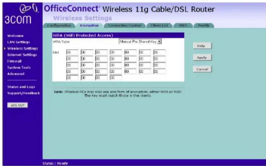
To set up Manual Pre-shared Key as the WPA Type:
1 Select Manual Pre-shared Key from the WPA Type drop-down box. The screen shown in Figure 37 displays.
2 Enter a pair of hexadecimal digits in each of the 32 Key fields. Each field can contain a hexadecimal number from 00 to ff, for example 1a.
3 Click Apply to generate the key.
Using Pre-Shared Passphrase
Figure 38 WPA Encryption Screen - Pre-Shared Passphrase

To set up Pre-Shared Passphrase as the WPA Type:
1 Select Pre-Shared Passphrase from the WPA Type drop-down box. The screen shown in Figure 38 displays.
2 Enter a phrase of between 8 and 63 characters in length in the Passphrase field. This passphrase will be used to generate a 256 bit key.
3 Click Apply to generate the key.
Configuring WEP Encryption
There are two levels of WEP encryption available, 64 bit (sometimes referred to as 40 bit) and 128 bit. Use the WEP Encryption Type box to select the desired level.
Encryption Keys
Figure 39 128 bit Encryption Keys Screen - WEP configuration

Figure 40 40 bit/64 bit Encryption Keys Screen - WEP Configuration

A Key is a hexadecimal (0-9, A-F) number used to encrypt and decrypt the data. There can be up to 4 keys and each key can be as long as 26 digits. The Router also offers a number of methods for converting plain text into hex keys. The text is much easier to remember than hex keys but it relies
on your wireless adapters also supporting this feature. Different manufacturers have developed different ways of converting plain text and so interoperability is not guaranteed. If you are experiencing difficulty, the Manual Hex Key method is supported by most vendors.
To set up WEP encryption:
1 Select 128 bit encryption or 40 bit/64 bit encryption from the WEP Encryption Type drop-down list.
2 Select a key generation method from the drop down list. If you have other wireless products choose the scheme that is compatible with these, then enter the appropriate information. The key generation method can be one of the following:
■ Manual Hex Key - This method allows you to manually enter hex keys. Virtually all manufacturers support this scheme. Enter a two digit hexadecimal number in every box. Hexadecimal numbers are formed from 0-9 and A-F.
■ 3Com Encryption String - This method is supported by 3Com Wireless products. The string can contain any alphanumeric characters and must be between 6 and 30 characters long. A single string will automatically generate 4 unique keys for 64 or 128 bit WEP.
■ASCII - This method is supported by some adapter cards running under Windows XP. The string must be exactly 5 characters for 64 bit WEP and 13 characters for 128 bit WEP. You must enter a separate string for each of the 4 Keys. You can leave a string blank provided this Key is not selected as the Active Transmit Key.
■ Passphrase - This is another common method and similar to the 3Com Encryption string. In 64 bit WEP, the passphrase will generate 4 different keys. However, in 128 bit WEP, this method only generates 1 key which is replicated for all 4 keys. The passphrase can be up to 31 characters long and may contain any alphanumeric characters.

If you encounter any difficulty when you enable WEP ensure that you check that each key on your wireless computer is exactly the same as each key on your Router. In other words, Key number 1 on the Wireless computer must have the same Hex number as Key number 1 on the Router, Key 2 on the Wireless computer must match Key 2 on the Router and so on.
3 Select the Active Transmit Key, which is the key the Router uses when it transmits. You can change the selected key periodically to increase the security of your network.
Some wireless adapters have only one key available on their WEP configuration page. If this is the case ensure it is the same as Key 1 on the Router and that it is selected as the active transmit key.
Connection Control
Figure 41 Connection Control Screen
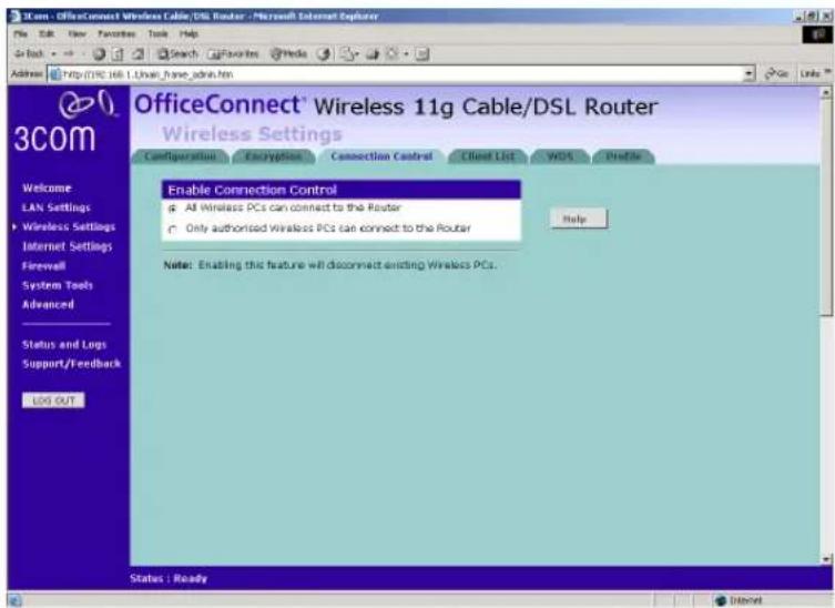
A higher level of security can be achieved for your wireless network if, in addition to using encryption, you specify that only certain wireless computers can connect to the Router. By default, any wireless computer that has the same Service Area Name/SSID, channel and encryption settings as the Router can connect to it.
To specify that only certain wireless computers can connect to the Router, select Only Authorized Wireless PCs can connect to the Router, and then click New. The screen shown in Figure 42 displays.

If you enable this feature from a Wireless PC, it will automatically be added to the Authorized Wireless PC list.
Authorized Wireless PCs
Figure 42 Connection Control Detail Screen

To create a list of Wireless computers that can access the Router:
1 Select the MAC addresses of the Wireless PC(s) for which you want to allow access.

To select multiple MAC addresses, hold down the Ctrl key while clicking on the addresses.

The drop down list on the Connection Control window will contain the MAC addresses of all Wireless PCs that are in range, currently operating, and have the same Service Area Name/SSID, channel and encryption settings as the Router. You will find this screen easier to use if you set up and make a note of all of your wireless PC's on your network first. You may also add the entries manually if you know the MAC address.
To add a MAC address that is not in the list, enter the MAC address in the Manual Entry section. A MAC address consists of 12 characters. Valid characters are '0-9', and 'A-F'.
2 Press Add.

Click Close to discard all changes.
Modifying a MAC Address
To modify a MAC address from the Connection Control screen:
1 Click on the MAC address to be modified. An example list is shown in Figure 43.
2 Modify the MAC address.
3 Press Apply to accept the changes.
Figure 43 MAC Address Table


Click Close to discard all changes.
Deleting a MAC Address
The connection rights for a Wireless PC listed in the table can be removed by pressing Delete for that entry in the table.

Once an entry has been deleted it cannot be undone. Please wait 30 seconds for changes to take effect.
Client List
Figure 44 Client List Screen
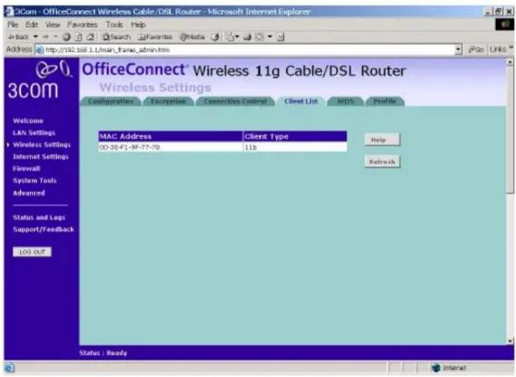
The Wireless Client List provides details on the devices that are connected to the Wireless LAN. The list is only created when Wireless Networking is enabled. For each device that is connected to the Wireless LAN, the MAC address and Connection Speed of that device is displayed. As you connect more devices to the Wireless LAN, the client list will grow to a maximum of 32 (the maximum number of wireless devices that the Router can support).
WDS Figure 45 WDS Screen
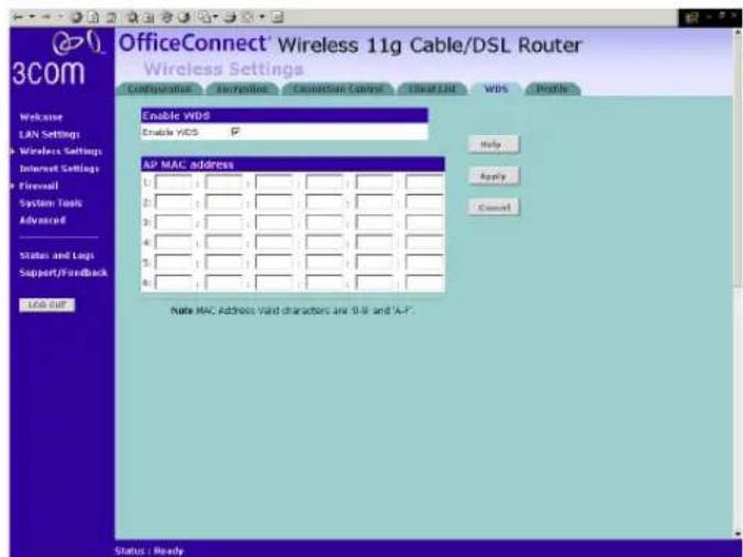
The Router supports the Wireless Distribution System (WDS) repeater mode. WDS repeating enables one or more Access Points to rebroadcast received signals to extend range and reach, though this can affect the overall throughput of data. To enable wireless repeating, check the Enable WDS check box, and then enter the MAC address(es) of one or more Access Points in the AP MAC Address table.
Profile Figure 46 Profile Screen
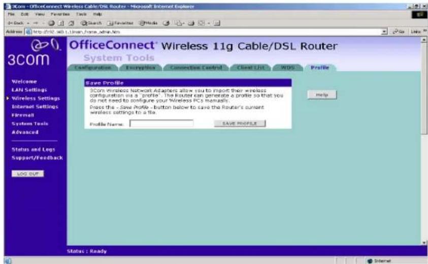
Some 3Com Wireless Network Adapters allow you to import Wireless configurations via a 'profile'. The Router can generate a profile so that you do not need to configure your Wireless PCs manually.
The profile contains three items as follows:
■Service Area Name/SSID of the Router
This is configured on the Configuration tab under the Wireless Settings option.
■Encryption settings from the Router
This is configured on the Encryption tab under the Wireless Settings option.
■Profile Name
This is used to identify the profile once it has been imported into the Wireless Network Adapter configuration software.
To set up a profile (once the Service Area Name/SSID and Encryption settings have been configured in the Router):
1 Enter a Profile Name (up to 25 alphanumeric characters) and then click Save Profile.
2 Your browser will then prompt you to enter a file name and folder location in which to save the profile. Once the profile has been saved it
can be copied on to another PC and imported into the 3Com Wireless Network Adapter.

For instructions on how to import a profile, refer to the User Guide that accompanies your 3Com Wireless Network Adapter(s).
If, once the profile is imported, the Wireless Network Adapter cannot connect to the Router, check that the adapter is within range of the Router
if Connection Control has been enabled in the Router, the MAC address of the Wireless Network Adapter must be included in the list of authorized Wireless PCs.
Internet Settings
Before you can configure the Router, you need to know the IP
information allocation method used by your ISP. There are four different ways that ISPs can allocate IP information, as described below:
1 Static IP Address (DSL or Cable)
The ISP provides the IP addressing information for you to enter manually. To configure the Router you will need to know the following:
■IP Address
■Subnet Mask
■ISP Router
■DNS address(es)
2 Dynamic IP Address (DSL or Cable)
Dynamic IP addressing (or DHCP) automatically assigns the Router IP information. This method is popular with Cable providers. This method is also used if your modem has a built in DHCP server.
3 PPPoE (DSL only)
If the installation instructions that accompany your modem ask you to install a PPPoE client on your PC, then select this option. To configure the Router you will need to know the following:
■User name
■Password
■Service Name (if required by your ISP)

When you install the Router, you will not need to use the PPPoE software on your PC.
4 PPTP (DSL or Cable)
PPTP is only used by some European providers. If the installation instructions that accompany your modem ask you to setup a dialup connection using a PPTP VPN tunnel then select this option. To configure the Router you will need to know the following:
■User name
■Password
■VPN Server address (usually your modem)

When you install the Router, you will not need to use the dialup VPN on your PC anymore.
5 L2TP (DSL or Cable)
L2TP is supported by some Internet Service Providers (ISPs). Check with your ISP to make sure L2TP is supported before selecting this option. To configure the Router you will need to know the following:
■User name
■Password
■L2TP Server address
Connection to ISP
Before beginning this section, ensure you have the required information from your ISP. (See "Before you Install your Router" on page 21.)
Select Internet Settings from the main menu to display Connection to ISP. Choose an IP Allocation Mode from the drop down box.
Select an IP Allocation Mode from the following:
■ Static IP address (to be specified manually) see page 67
■ Dynamic IP address (automatically allocated) see page 68
■ PPPoE (used by DSL providers only) see page 69
■ PPTP (used by some European providers) see page 70
■ L2TP (supported by some ISPs) see page 72
Static IP Address
Figure 47 Connection Parameters Screen - Static IP

To setup the Router for use with a Static IP address connection:
1 Select Static IP Address (to be specified manually) in the IP Allocation Mode field (Figure 47).
2 Enter your IP Address in the IP Address text box.
This information, along with the rest of the information in this screen, should be provided to you by your ISP. If the information is already entered, your ISP has pre-configured your Router, and you should go to step 7.
3 Enter your subnet mask in the Subnet Mask text box.
4 Enter your ISP Router address in the ISP Gateway Address text box.
5 Enter your primary DNS address in the Primary DNS Address text box.
6 Enter your secondary DNS address in the Secondary DNS Address text box.
This step is optional. Not all ISPs require a secondary DNS address.
7 Check all of your settings, and then click Apply.
Dynamic IP Address
Figure 48 Connection Parameters Screen - Dynamic IP
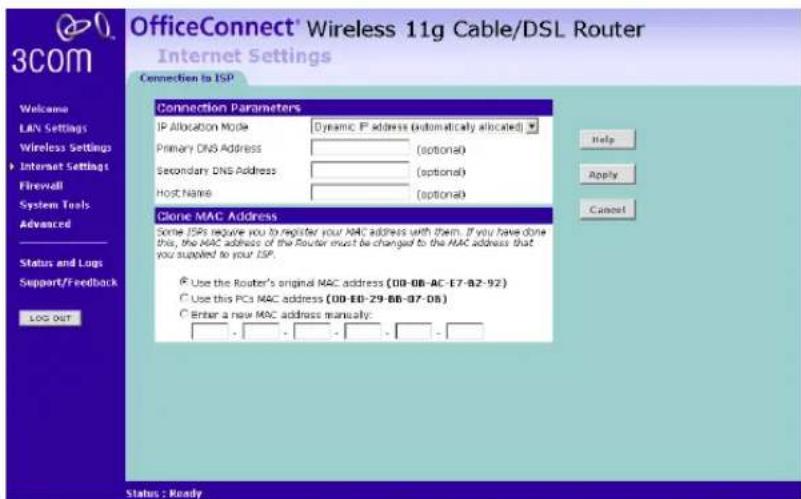
If this mode is selected, your IP Address, Subnet Mask, and DNS Address will be obtained automatically from your ISP. They are not displayed on this screen, but may be viewed on the Status screen (click on Status and Logs on the left hand menu bar).
To setup the Router for use with a dynamic IP address connection:
1 Select Dynamic IP Address (automatically allocated) in the IP Allocation Mode field. (Figure 48)
2 Enter your Primary DNS Address and Secondary DNS address.
Your ISP may provide you with primary and secondary DNS addresses. If they have been provided, enter the addresses in the appropriate text boxes. If not, leave 0.0.0.0 in the boxes.
3 Enter the Host Name (optional).
Some ISPs require a host name. If your ISP has this requirement, enter the host name in the Host Name text box.
4 If you use 'Cable', your ISP may use your MAC address to authenticate you. If this is the case, you will need to 'Clone' your MAC address. There are three options:
- Use the Router's original Internet MAC address - This field is selected by default and is automatically filled in with the MAC address of the Router.
- Use this PC's MAC address - This field is automatically filled in with the MAC address of the PC you are using to configure the Router. You should use this address only if you were previously using this computer to connect directly to your modem.
■ Enter a new MAC address manually - Use this option if you want to specify a new MAC address. Enter the new MAC address.
5 Check all settings and click Apply.
PPP over Ethernet
Figure 49 PPPoE Setup Screen

To setup the Router for use with a PPP over Ethernet connection, use the following procedure:
1 Select PPP over Ethernet in the IP Allocation Mode field. (Figure 49)
2 Enter your Primary DNS Address and Secondary DNS address.
Your ISP may provide you with primary and secondary DNS addresses. If they have been provided, enter the addresses in the appropriate text boxes. If not, leave 0.0.0.0 in the boxes.
3 Enter the Host Name (optional).
Some ISPs require a host name. If your ISP has this requirement, enter the host name in the Host Name text box.
4 Enter your PPP over Ethernet user name in the PPPoE User Name text box.
5 Enter a password in the PPPoE Password text box.
6 Enter your PPP over Ethernet service name in the PPPoE Service Name text box. Not all ISPs require a PPPoE service name. Only enter a service name if your ISP requires this.
7 Enter the MTU value supplied by your ISP. If you do not know this, leave it at the default value. The default is 1454.
8 Select an idle time from the Maximum Idle Time drop-down list.
This value will correspond to the amount of idle time (no Internet activity) that will pass before the Router automatically ends your PPP over Ethernet session.

Since the Router contains its own PPPoE client, you no longer need to run PPPoE client software on your computer to access the Internet.
PPTP
Figure 50 PPTP Setup Screen

To setup the Router for use with a PPTP connection, use the following procedure:
1 Select PPTP (used by some European providers) in the IP Allocation Mode field. (Figure 50)
2 Enter your PPTP server address in the PPTP Server Address text box (this is typically the address of your modem).
3 Enter your PPTP user name in the PPTP User Name text box.
4 Enter your password in the PPTP Password text box.
5 Enter your Primary DNS Address and Secondary DNS address.
Your ISP may provide you with primary and secondary DNS addresses. If they have been provided, enter the addresses in the appropriate text boxes. If not, leave 0.0.0.0 in the boxes.
6 Enter the MTU value supplied by your ISP. If you do not know this, leave it at the default value. The default is 1460.
7 Select an idle time from the Maximum Idle Time drop-down list.
This value will correspond to the amount of idle time (no Internet activity) that will pass before the Router automatically ends your PPTP session.
8 IP settings must be used when establishing a PPTP connection. To obtain an IP address, either:
- Check the Get IP By DHCP check box, if you want to obtain an IP address from a DHCP Server on the network.
With this check box enabled, you can click Release to release the WAN IP Address for the Router, or click Renew to renew the current WAN IP Address, using DHCP. - Fill in the Initial IP Address, Initial Subnet Mask and Initial Gateway fields if your ISP has provided you with these settings. Alternatively, if the PPTP server is located in your DSL modem, click Suggest to select an IP address on the same subnet as the PPTP server.
Check all of your settings, and then click Apply.
L2TP
Figure 51 L2TP Setup Screen
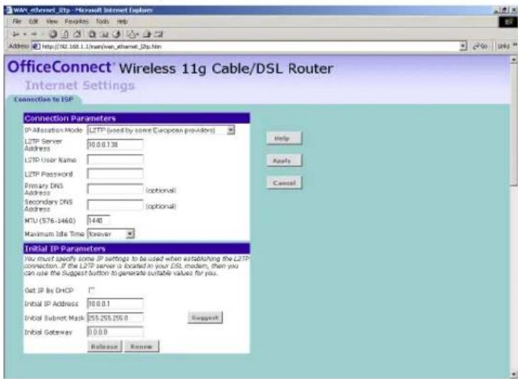

Check with your ISP to make sure they support L2TP.
To set up the Router for use with an L2TP connection, use the following procedure:
1 Select L2TP (used by some European providers) in the IP Allocation Mode field.
2 Enter your L2TP server address in the L2TP Server Address text box.
3 Enter your L2TP user name in the L2TP User Name text box.
4 Enter your L2TP password in the L2TP Password text box.
5 Enter your Primary DNS Address and Secondary DNS Address.
Your ISP may provide you with primary and secondary DNS addresses. If they have been provided, enter the addresses in the appropriate text boxes. If not, leave 0.0.0.0 in the boxes.
6 Enter the MTU value supplied by your ISP. If you do not know this, leave it at the default value. The default is 1440.
7 Select an idle time from the Maximum Idle Time drop-down list.
This value will correspond to the amount of idle time (no Internet activity) that will pass before the Router automatically ends your PPTP session.
8 IP settings must be used when establishing an L2TP connection. To obtain an IP address, either:
- Check the Get IP by DHCP check box if you want to obtain the IP information from a DHCP Server on the network.
With this check box enabled, you can click Release to release the WAN IP Address for the Router, or click Renew to renew the current WAN IP Address, using DHCP.
■ Fill in the Initial IP Address, Initial Subnet Mask and Initial Gateway fields if your ISP has provided you with these settings. Alternatively, if the L2TP server is located in your DSL modem, click Suggest to select an IP address on the same subnet as the L2TP server.
Check all of your settings, and then click Apply.
Firewall
On the main frame of the Firewall setup screen is a menu with six tabs: Virtual Servers, Special Applications, PCs Privileges, URL Filter, Content Filter and SPI.
Virtual Servers
Selecting the Firewall option on the main menu displays the Virtual Servers setup screen. (Figure 52)
Virtual DMZ
Figure 52 Virtual Servers Screen

DMZ (De-Militarized Zone) Host is a computer without the protection of the firewall. This feature allows a single computer to be exposed to unrestricted 2-way communication from outside of your network. This
feature should be used only if the Virtual Server or Special Applications options do not provide the level of access needed for certain applications.
To configure one of your computers as a DMZ host, enter the last digit(s) of the IP address of the computer in the IP Address of DMZ Host text box, and then click Apply.
Virtual Server
Activating and configuring a virtual server allows one or more of the computers on your network to function as a public server. For example, one of your computers could be configured as an FTP server, allowing others outside of your office network to download files of your choosing. Or, if you have created a Web site, you can configure one of your computers as a Web server, so that others can view your Web site.
To configure a virtual server:
1 Click New on the right side of the screen to open the Virtual Server Settings dialogue box. (Figure 53)
2 Enter the last digit(s) of the IP address of the computer in the Server IP Address text box.
3 Either:
■ Select a Local Service other than Custom from the drop-down list. (Figure 53), or
Figure 53 Virtual Servers Settings Screen

■ Select Custom from the drop-down list to display screen shown in Figure 54. Specify a suitable name for the service and then enter the port numbers required for that service.
Figure 54 Custom Setup Screen

Click Add to return to the Virtual Server Settings screen.
4 Click Apply to save the settings.
The port numbers are specified using a comma-separated list, with hyphens to denote port number ranges. So for example, entering 2, 3, 5-7 would cause ports 2, 3, 5, 6, and 7 to be activated.
Special Applications
Figure 55 Special Applications Screen

Select Special Apps tab to display Authorized Application setup screen. (Figure 55)
Some software applications require special or multiple connections to the Internet and these would normally be blocked by the firewall. For example Internet Telephony or Video conferences require multiple connections.
So that these special applications can work properly and are not blocked, the firewall needs to be told about them. In each instance there will be a
trigger port and incoming port(s), where traffic on the trigger port tells the firewall to open the incoming ports.

Each defined Special Application only supports a single computer user, and up to 10 Special Applications can be defined. Any incoming ports opened by a Special Application trigger will be closed after five minutes of inactivity.
To configure special applications:
1 Click New to display the Special Application Settings screen (Figure 56).
Figure 56 Special Application Settings Screen

2 Either:
■ Select the application from the Choose Application drop-down list, or
■ Select Other to specify an Application Name for the special application and then enter a value in the Trigger Port and Incoming Ports text boxes (Figure 57). These values correspond to the outbound port numbers issued by the application.
The port numbers are specified using a comma-separated list, with hyphens to denote port number ranges. So for example, entering 2, 3, 5-7 would cause ports 2, 3, 5, 6, and 7 to be activated.

The Router will automatically allow FTP and NetMeeting sessions. You do not need to configure these as Special Applications.
Figure 57 Other Applications Setup Screen

Click Add to save your settings.
3 Click Add in the Special Application Settings screen (Figure 56), to save the configuration.

Only one computer on your network can use the special application at any one time.
PC Privileges Figure 58 PC Privileges Screen
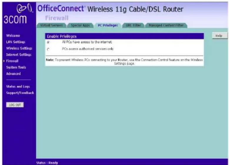
Select PC Privileges to display the PC Privilege setup screen (Figure 58).
Access from the local network to the Internet can be controlled on a computer-by-computer basis. In the default configuration the Router will allow all connected computers unlimited access to the Internet.
PC Privileges allows you to assign different access rights for different computers on your network.
To use access control for all computers:
1 Click PCs access authorized services only.
2 Select All PCs to set up the access rights for all computers connected to the Router. The screen shown in Figure 59 displays.
Figure 59 All PCs Setup Screen

3 If required, check the Bypass URL Filter check box to override the URL Filter settings. Refer to "URL Filter" on page 80.
4 Select the authorized services by clicking in the appropriate check box(es).
5 In addition to the four authorized services listed, you can choose to allow or block access to other services. You can either:
■ Allow all other services, or allow all other services with exceptions, or
■ Block all other services, or block all other services with exceptions.
To do this, select Allow or Block from the drop down menu and, if required, enter the exceptions into the text box.
The port numbers are specified using a comma-separated list, with hyphens to denote port number ranges. So for example, entering 2, 3, 5-7 would cause ports 2, 3, 5, 6, and 7 to be activated.

For example, to block access to all services except Web (80) and a service that uses ports 2,3,5,6 and 7:
- Tick the Web(80) check box.
- Select 'Block' all other services.
- Enter '2, 3, 5-7' in the 'except (specify ports) box. See Figure 59.
6 If required, you can schedule when PCs can access the Internet. By default, all PCs can access the internet all day, every day. To change the
schedule, check the appropriate check box for each day you want to allow access, and enter the permitted access times for each day in 24-hour clock format.
For example, to allow access Monday through Friday between 9 am and 5 pm, check the check boxes for Mon, Tue, Wed, Thu and Fri, and enter 09:00 and 17:00 in the text boxes next to each of these days.
7 Click Modify to save the settings or Close to discard them.
To assign different access rights for different computers:
1 If not already selected, click PCs access authorized services only.
2 Click New to set up access rights for individual computers. The PC Privileges setting screen displays, as shown in Figure 60.
Figure 60 Individual PCs Setup Screen

3 Enter the last digit(s) of the IP address of the computer in the PC's IP Address text box.
4 If required, check the Bypass URL Filter check box to override the URL Filter settings. Refer to "URL Filter" on page 80.
5 Select authorized services by clicking in the appropriate check box(es).
6 In addition to the four authorized services listed, you can choose to allow or block access to other services. You can either:
■ Allow all other services, or allow all other services with exceptions, or
■ Block all other services, or block all other services with exceptions.
To do this, select Allow or Block from the drop down menu and, if required, enter the exceptions into the text box.
See step 6 of the previous section for more details.
7 If required, you can schedule when this PC can access the Internet. To set the schedule, check the appropriate check box for each day you want to
allow access, and enter the permitted access times in 24-hour clock format.
For example, to allow access Monday through Friday between 9 am and 5 pm, check the check boxes for Mon, Tue, Wed, Thu and Fri, and enter 09:00 and 17:00 in the text boxes next to each of these days.
8 Click Add to save the settings.
URL Filter Select the URL Filter tab to set the URLs you want your clients to be able to access. The Router's URL Filter has three settings:
■ Disabled — Users can browse all Web sites. None will be filtered.
■ Deny List — Users can browse all Web sites apart from those sites listed in the deny list and those whose URLs contain keywords listed in the deny list. See "Deny List" on page 80.
- Allow List — Users are unable to browse any Web sites except of those listed in the allow list and those whose URLs contain keywords listed in the allow list. See "Allow List" on page 81.
Deny List
To allow users access to all Web sites except for those you choose to block, choose Deny List in the URL Filter Type drop-down box (Figure 61).
Figure 61 URL Filter Screen showing Deny List
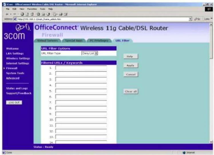
To filter a specific site, enter the URL for that site. For example, to stop your users from browsing a site called www.badsite.com, enter www.badsite.com or badsite.com in one of the fields.
If badsite.com has multiple sub-domains, such as this.badsite.com and that.badsite.com then you can either:
■ Block them individually by entering this.badsite.com in one field and that.badsite.com in another.
or
■ Block them by entering the keyword badsite.com into one of the fields. This will block all URLs containing the string badsite.com. As well as blocking this.badsite.com and that.badsite.com, the keyword badsite.com would block searches that mentioned badsite.com in their domain name, for example www.notabadsite.com.
To filter a generic keyword enter it into one of the fields. You should exercise caution when choosing a keyword as many keywords are contained within other words. For example, filtering the word sex would filter the following example URLs:
■www.sussex.com
■www.thisexample.com
You can filter up to 30 keywords and URLs.

Computers that should not be subject to URL filtering can be excluded by ticking the Bypass URL Filter check box in the PC Privileges setup screen. See "PC Privileges" on page 77.
Allow List
To stop users from accessing any Web sites that you have not specifically allowed, choose Allow List in the URL Filter Type drop-down box (Figure 62).
Figure 62 URL Filter Screen showing Allow List
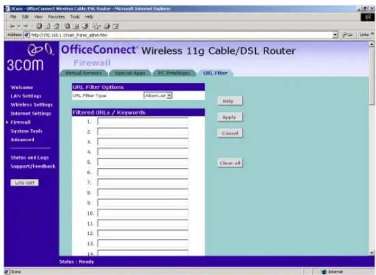
To allow a specific site, enter the URL for that site. For example, to let your users browse a site called www.goodsite.com, enter www.goodsite.com or goodsite.com in one of the fields.
If goodsite.com has multiple sub-domains, such as this.goodsite.com and that.goodsite.com then you can either:
- Allow them individually by entering this.goodsite.com in one field and that.goodsite.com in another.
or - Allow them by entering the keyword goodsite.com into one of the fields. This will allow all URLs containing the string goodsite.com. As well as allowing this.goodsite.com and that.goodsite.com, the keyword goodsite.com would allow sites that had the string goodsite.com in their URL, for example xxxgoodsite.com.
To filter a generic keyword enter it into one of the fields. You should exercise caution when choosing a keyword as sites that you may wish to block may be allowed if you choose too general a keyword.

The Router filters all traffic from domains that have been blocked using the URL filter. If you need to access an external mail server, FTP server or other named device outside your network, you must list it in one of the allow fields.
You can filter up to 30 keywords and URLs.

Computers that should not be subject to URL filtering can be excluded by ticking the Bypass URL Filter checkbox in the PC Privileges setup screen. See "PC Privileges" on page 77.
Content Filter
You can subscribe to the 3Com Content Filter Service, which enables you to block or allow the URLs of a number of pre-defined categories.

The Router comes with a 14-day free trial of the 3Com Content Filter Service. To activate the 14-day free trial of the service, you must first register your Router at www.3com.com. To continue using the service after the trial period, you must purchase the full 3Com Content Filter Service (3CSBCFS).

URL filtering rules supersede content filtering rules. If the 3Com Content Filter is blocking certain Web sites that you want to allow, you can add these sites to URL Filter's allow list. Refer to "Allow List" on page 81 for more information.
To activate Content Filtering:
1 Select Firewall from the main menu, then select the Content Filter tab. The Content Filter screen displays (Figure 63).
Figure 63 Content Filter Screen
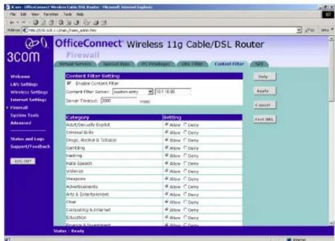
2 Make sure the Enable Content Filter check box is checked.
3 Select the Content Filter Server that you require from the drop-down list. If you select custom entry, enter the server IP address in the text box.
4 Select the Server Timeout value in milliseconds. The default is 3000 milliseconds (3 seconds).
5 Select Allow or Deny for each displayed category, as required. Click Apply to save the settings.
SPI Stateful Packet Inspection (SPI) inspects, and if required blocks packets at the application layer. SPI also maintains TCP and UDP session information, including timeouts and the number of active sessions, and provides the ability to detect and prevent certain types of network attacks such as DoS attacks.

Denial of Service (DoS) attacks are aimed at devices and networks with a connection to the Internet. The goal is not to steal information, but to disable a device or network so users no longer have access to network resources.
To configure SPI information on your Router:
1 Select Firewall from the main menu, then select the SPI tab to display the SPI screen (Figure 64 and Figure 65):
Figure 64 SPI Screen - upper section
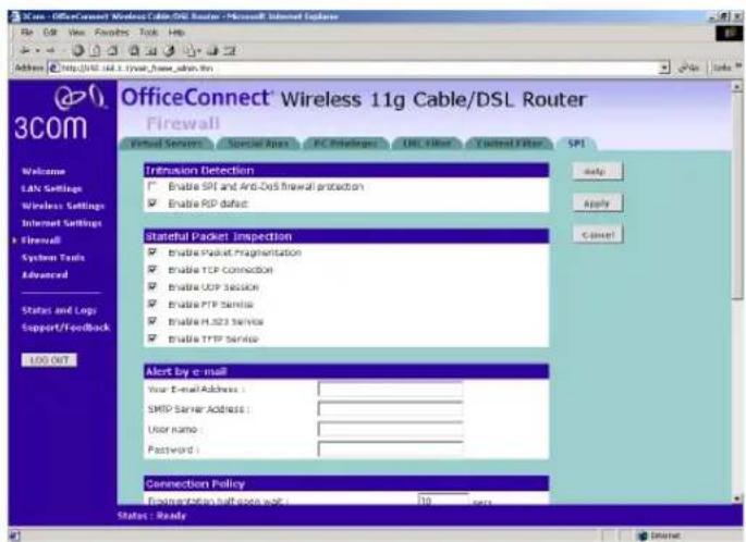
Figure 65 SPI Screen - lower section

Intrusion Detection Feature
The Intrusion Detection feature limits access for incoming traffic at the WAN ports.
2 Check the Enable SPI and Anti-DoS firewall protection check box to enable SPI. When this feature is enabled, all incoming packets will be blocked except for those types that you allow in the Stateful Packet Inspection section.
3 If required, check the Enable RIP defect check box. This feature stops unacknowledged packets from accumulating in the input queue.
Stateful Packet Inspection
4 The Stateful Packet Inspection section displays a list of traffic types. If you leave the check box for a traffic type blank, this traffic type is blocked. If you check the check box, the Router allows this type of incoming traffic, but only if the connection was initiated from the local LAN.
For example, if you check only the Enable FTP Service check box, all incoming traffic is blocked except for FTP connections initiated from the local LAN.
Alert by E-mail
5 In the Your E-mail Address text box, enter the e-mail address you want alerts to be sent in the event of a hacker attack.
6 Enter your SMTP Server Address.
7 Enter your SMTP Server User Name.
8 Enter your SMTP Server Password.
Connection Policy
9 In the Fragmentation half-open wait text box, enter the length of time, in seconds, that you want an unassembled packet to remain active before the Router drops it. The default is 10 seconds.
10 In the TCP SYN wait text box, enter the length of time, in seconds, that you want the Router to wait for a TCP session to synchronize before it drops the session. The default is 30 seconds.
11 In the TCP FIN wait text box, enter the length of time, in seconds, that you want a TCP session to remain active after the Router detects a FIN packet. The default is 5 seconds.
12 In the TCP connection idle timeout text box, enter the length of time, in seconds, that you want a TCP session to remain active if there is no activity. The default is 3600 seconds (1 hour).
13 In the UDP session idle timeout text box, enter the length of time, in seconds, that you want a UDP session to remain active if there is no activity. The default is 30 seconds.
14 In the H.323 data channel idle timeout text box, enter the length of time, in seconds, that you want an H.323 session to remain active if there is no activity. The default is 180 seconds.
DoS Detect Criteria
15 In the Total incomplete TCP/UDP sessions HIGH text box, enter the number of unestablished sessions that will cause the software to start deleting half-open sessions. The default is 300.
16 In the Total incomplete TCP/UDP sessions LOW text box, enter the number of unestablished sessions that must be reached before the software stops deleting half-open sessions. The default is 250.
17 In the Incomplete TCP/UDP sessions (per min) HIGH text box, enter the maximum number of incomplete TCP/UDP sessions allowed per minute. The default is 250 sessions.
18 In the Incomplete TCP/UDP sessions (per min) LOW text box, enter the minimum number of incomplete TCP/UDP sessions allowed per minute. The default is 200 sessions.
19 In the Maximum incomplete TCP/UDP sessions number from the same host text box, enter the maximum number of incomplete sessions allowed from the same host. The default is 10 sessions.
20 In the Incomplete TCP/UDP sessions detect sensitive time period text box, enter the length of time that must elapse before an incomplete TCP/UDP session is detected as incomplete. The default is 300 msec.
21 In the Maximum half-open fragmentation packet number from the same host text box, enter the maximum number of half-open fragmentation packets allowed from the same host. The default is 30 packets.
22 In the Half-open fragmentation detect sensitive time period text box, enter the length of time that must elapse before a half-open fragmentation session is detected as half-open. The default is 10000 msec.
23 In the Flooding cracker block time text box, enter the length of time that must elapse between detection of a flood attack and blocking the attack. The default is 300 seconds.
Click Apply to save the settings.
Restart Figure 66 Restart Screen

If your Router is not operating correctly, you can choose to restart the Router by selecting Restart the Router, simulating the effect of power cycling the unit. No configuration information will be lost but the log files will be erased. This function may be of use if you are experiencing problems and you wish to re-establish your Internet connection. Any network users who are currently accessing the Internet will have their access interrupted whilst the restart takes place, and they may need to reboot their computers when the restart has completed and the Router is operational again.
Time Zone Figure 67 Time Zone Screen
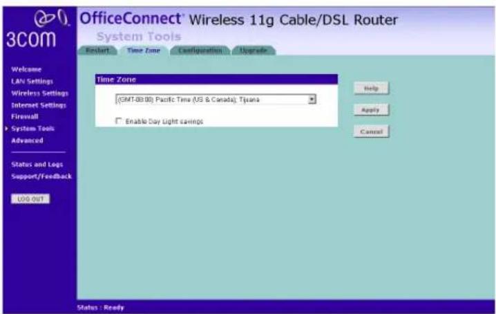
Choose the time zone that is closest to your actual location. The time zone setting is used by the system clock when displaying the correct time in the log files.
If you use Daylight saving tick the Enable Day Light savings box, and then click Apply (Figure 67).
The Router reads the correct time from NTP servers on the Internet and sets its system clock accordingly. The Daylight Savings option merely advances the system clock by one hour. It does not cause the system clock to be updated for daylight savings time automatically.
Configuration
Figure 68 Configuration Screen

Select the Configuration tab to display the Configuration screen (Figure 68).
Backup Configuration
Click BACKUP to save the current Router configuration. You will be prompted to download and save a file to disk.
Restore Configuration Data
If you want to reinstate the configuration settings previously saved to a file, press Browse to locate the backup file on your computer, and then click RESTORE to copy the data into the Router's memory.

The password will remain unchanged.
Reset to Factory Default
If you want to reset the settings on your Router to those that were loaded at the factory, click RESET. You will lose all your configuration changes. The Router LAN IP address will revert to 192.168.1.1, and the DHCP server on the LAN will be enabled. You may need to reconfigure and restart your computer to re-establish communication with the Router.
Upgrade
Figure 69 Upgrade Screen
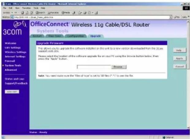
The Upgrade facility allows you to install on the Router any new releases of system software that 3Com may make available. To install new software, you first need to download the software from the 3Com support web site to a folder on your computer. Once you have done this, select Browse to tell your web browser where this file is on your computer, and then click Apply. The file will be copied to the Router, and once this has completed, the Router will restart. Although the upgrade process has been designed to preserve your configuration settings, it is recommended that you make a backup of the configuration beforehand, in case the upgrade process fails for any reason (for example, the connection between the computer and the Router is lost while the new software is being copied to the Router).
The upgrade procedure can take up to two minutes, and is complete when the Alert LED has stopped flashing and is permanently off. Make sure that you do not interrupt power to the Router during the upgrade procedure; if you do, the software may be corrupted and the Router may not start up properly afterwards. If the Alert LED comes on continuously after a failed upgrade, refer to Chapter 6, "Troubleshooting".
Advanced
Selecting Advanced from the main menu displays the following five tabs in your Web browser window: Static Route, RIP, Routing Table, DDNS and Security.
Static Route
The Router supports static route functionality. Select the Static Route tab to display the screen shown in Figure 70
Figure 70 Static Route screen

The following information is displayed for each static route:
■Index - the index of the static route
■Network Address - the network address of the route. If network address and subnet mask are both set to 0.0.0.0, this is the default route.
■Subnet Mask - the subnet mask of the route. If network address and subnet mask are both set to 0.0.0.0, this is the default route.
■ Gateway - the gateway used to route data to the network specified by the network address.
RIP The Router supports the Routing Information Protocol (RIP). RIP allows you to set up routing information on one RIP enabled device, and have that routing information replicated to all RIP enabled devices on the network. LAN and WAN interfaces can be configured independently of each other.
Select the RIP tab to display the screen shown in Figure 71
Figure 71 RIP screen
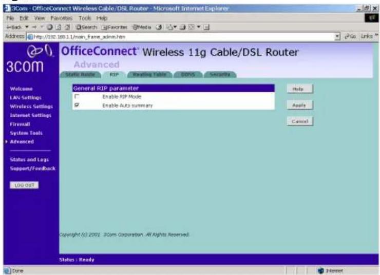
Setting Up RIP
Check the Enable Auto Summary check box if you want the Router to send simplified routing data to other RIP devices, instead of full routing data.
Check the Enable RIP Mode check box to configure RIP on the Router. The screen shown in Figure 72 displays
Figure 72 Enable RIP Mode screen

The screen displays RIP information for the LAN interface and WAN interface. To set up or change the information for one or both interfaces:
1 Select one of Disable, Enable or Silent from the Operation Mode drop-down list. If you select Enable, the Router transmits RIP update information to other RIP enabled devices. If you select Silent, the Router only receives RIP update messages.
2 Select either 1 (for RIPv1) or 2 (for RIPv2) from the Version drop-down list. 3Com recommends that you use RIPv1 if there is any RIP enabled device on your network that does not support RIPv2. In all other case, select RIPv2.
3 Select either Enable or Disable from the Poison Reverse drop-down list. Poison Reverse is a feature that helps prevent data loops.
4 Select one of None, Password or MD5 from the Authentication Required drop-down list. If you select Password, an unencrypted text password must be set on all RIP-enabled devices. If you select MD5, the password must be encrypted using the MD5 encryption algorithm.
5 If you selected Password or MD5 at step 4, enter a password at the Authentication Code prompt.
Routing Table Select the Routing table tab to display routing information used by the Router. The information is displayed in the format shown in Figure 73
Figure 73 Routing Table screen

DDNS Dynamic Domain Name Server (DDNS) enables you to map a static domain name to a dynamic IP address. The Router supports two DDNS providers, TZO.com and DYNDNS.org. Before you can set up DDNS, you must obtain an account, password and static domain name from your DDNS provider. DDNS is disabled by default.
To set up DDNS:
1 Select Advanced from the main menu, then select the DDNS tab. The DDNS screen displays (Figure 74).
Figure 74 DDNS screen
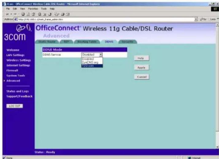
2 Select a DDNS Service provider from the drop-down list. This can be either TZO.com or DynDNS.org.
TZO.com
If you select TZO.com:
1 In the Domain Name text box, enter the domain name.
2 In the Username/E-mail text box, enter the account name.
3 In the Key text box, enter the account password.
4 In the Refresh Time box, enter how often you want the service to automatically refresh, in days. The default is three days.
5 Click Apply to make this service active.
DynDNS.org
If you select DYNDNS.org:
1 In the Host Name text box, enter the host name.
2 In the Username text box, enter the account name.
3 In the Password text box, enter the account password.
4 In the Refresh Time box, enter how often you want the service to automatically refresh, in days. The default is three days.
5 Click Apply to make this service active.
Security Select Security to display the Security screen (Figure 75).
Figure 75 Security Screen

The Internet connects millions of computer users throughout the world. The vast majority of the computer users on the Internet are friendly and have no intention of breaking into, stealing from, or damaging your network. However, there are hackers who may try to break into your network. The options in the Security tab features help you to protect your network.
Using Advanced Settings
The Advanced Settings section of the Security screen displays the following options:
■Enable universal plug and play - Universal plug and play allows compatible software to read and change some the Router's firewall settings. This reduces the configuration required but lessens your control of the Router's firewall.
Check on the check box to enable this feature, and then select Apply.

3Com recommends that you leave this feature disabled for maximum security.
- Allow PING from the Internet - PING is a utility, which is used to determine whether a device is active at the specified IP address. PING is normally used to test the physical connection between two devices, to ensure that everything is working correctly.
By default the Router has PING disabled in order to make the device more difficult to find on the Internet and less prone to attack.
Check on the check box to enable this feature, and then select Apply.

3Com recommends that you leave this feature disabled for maximum security.
■Disable NAT - Network Address Translation (NAT) is the method by which the Router shares the single IP address assigned by your ISP with the computers on the network. Only disable NAT if your ISP assigns you multiple IP addresses or you need NAT disabled for an advanced system configuration. If you have a single IP address and your turn NAT off, the computers on your network will not be able to access the Internet. Other problems may also occur.
Check on the check box to disable NAT, and then select Apply.

3Com recommends that you leave this feature enabled for maximum security.
Enabling Remote Administration
It is possible to administer the Router remotely. Select one of the following options for remote administration:
■ Disable Remote Administration - This option is set as default.
■ Enable administration from a single Internet Host - Only the specified Host IP Address can manage the Router. Any other users will be rejected.
■ Enable administration from a whole subnet - This option allows a number of users within the specified Host Network Address and Subnet Mask to administer the Router.
■ Enable administration from any Internet Host - This option allows any host to access the administration pages.
To remotely administer your Router, enter
http://xxx.xxx.xxx.xxx:8000 in the location bar of the browser running on the remote computer, where xxx.xxx.xxx.xxx is the Internet IP
address of the Router. You may then login using the administration password.

Your Internet IP address can be found at the bottom of the screen. See Figure 75.
Status and Logs
Selecting Status and Logs from the main menu displays the Status, Usage, and Logs screens in your Web browser window.
Status The Status screen displays a tabular representation of your network and Internet connection. (Figure 76 and Figure 77).
Figure 76 Status Screen - upper section

Figure 77 Status Screen - lower section

Usage Usage displays an approximate count of the traffic since the Router was last reset. (Figure 78)

The counts are approximate and should be used as a guide only. Contact your ISP for accurate logging information.
Figure 78 Usage Screen
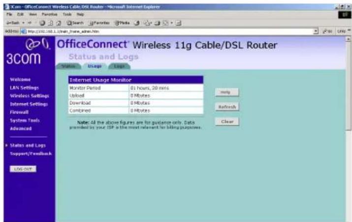
Logs Logs will allow you to view both the normal events, and security threats logged by the Router.
Figure 79 Logs Screen

You may be asked to refer to the information on the Status and Logs screens if you contact your supplier for technical support.
Support/Feedback
Selecting Support/Feedback from the main menu displays the Support and Feedback screens.
Support Figure 80 Support Screen

Selecting the Support option on the main menu displays the support links screen, which contains a list of Internet links that provide information and support concerning the Router (Figure 80).
Feedback
Figure 81 Feedback Screen
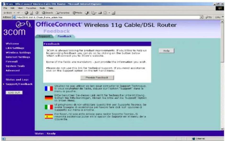
Selecting the Feedback option displays the Feedback screen and allows you to provide feedback to 3Com on the operation of your Router (Figure 81). This screen should not be used to obtain technical support.
6
TROUBLESHOOTING
Basic Connection Checks
■Check that the Router is connected to your computers and to the cable/DSL modem, and that all the equipment is powered on. Check that the LAN Status and Cable/DSL Status LEDs on the Router are illuminated, and that any corresponding LEDs on the cable/DSL modem and the NIC are also illuminated.
■ Ensure that the computers have completed their start-up procedure and are ready for use. Some network interfaces may not be correctly initialized until the start-up procedure has completed.
■ If the link status LED does not illuminate for a port that is connected, check that you do not have a faulty cable. Try a different cable.
Browsing to the Router Configuration Screens
If you have connected your Router and computers together but cannot browse to the Router configuration screens, check the following:
■ Confirm that the physical connection between your computer and the Router is OK, and that the LAN Status LEDs on the Router and NIC are illuminated and indicating the same speed (10Mbps or 100Mbps). Some NICs do not have status LEDs, in which case a diagnostic program may be available that can give you this information.
■ Ensure that you have configured your computer as described in Chapter 3, Setting Up Your Computers. Restart your computer while it is connected to the Router to ensure that your computer receives an IP address.
■When entering the address of the Router into your web browser, ensure that you use the full URL including the http://prefix (e.g. http://192.168.1.1).
■Ensure that you do not have a Web proxy enabled on your computer. Go to the Control Panel and click on Internet Options. Select the
Connections tab and click on the LAN Settings button at the bottom. Make sure that the Proxy Server option is unchecked.
If you cannot browse to the Router, use the winipcfg utility in Windows 95/98/ME to verify that your computer has received the correct address information from the Router. From the Start menu, choose Run and then enter winipcfg. Check that the computer has an IP address of the form 192.168.1.xxx (where xxx is in the range 2-254), the subnet mask is 255.255.255.0, and the default Router is 192.168.1.1 (the address of the Router). If these are not correct, use the Release and Renew functions to obtain a new IP address from the Router. Under Windows 2000, use the ipconfig command-line utility to perform the same functions.
■If you still cannot browse to the Router, then use the Discovery program on the accompanying CD-ROM as described in Appendix A.
Connecting to the Internet
If you can browse to the Router configuration screens but cannot access sites on the Internet, check the following:
■Confirm that the physical connection between the Router and the cable/DSL modem is OK, and that the link status LEDs on both Router and modem are illuminated.
■Confirm that the connection between the modem and the cable/DSL interface is OK.
■Ensure that you have entered the correct information into the Router configuration screens as required by your Internet Service Provider. Use the "Internet Settings" screen to verify this.
■For DSL users, check that the PPPoE or PPTP user name, password and service name are correct, if these are required. Only enter a PPPoE service name if your ISP requires one.
■For cable users, check whether your ISP requires a fixed MAC (Ethernet) address. If so, use the Clone MAC Address feature in the Router to ensure that the correct MAC address is presented, as described on page 68.
■ For cable users, check whether your ISP requires a fixed Host Name. If so, enter the required Host Name in the Internet Settings screen.
■Ensure that your computers are not configured to use a Web proxy. On Windows computers, this can be found under Control Panel > Internet Options > Connections.
Forgotten Password and Reset to Factory Defaults
If you can browse to the Router configuration screen but cannot log on because you do not know or have forgotten the password, follow the steps below to reset the Router to it's factory default configuration.

CAUTION: All your configuration changes will be lost, and you will need to run the configuration wizard again before you can re-establish your Router connection to the Internet. Also, other computer users will lose their network connections whilst this process is taking place, so choose a time when this would be convenient.
1 Remove power from the Router.
2 Disconnect all your computers and the cable/DSL modem from the Router.
3 Using a straight through Ethernet cable, connect the Ethernet Cable/DSL port on the rear of the Router to any one of the LAN ports.
4 Re-apply power to the Router. The Alert LED will flash as the Router starts up, and after approximately 30 seconds will start to flash more slowly (typically 2 seconds on, 2 seconds off). Once the Alert LED has started to flash slowly, remove power from the Router.
5 Remove the cable connecting the Cable/DSL port to the LAN port, and reconnect one of your computers to one of the Router LAN ports.
6 Re-apply power to the Router, and when the start-up sequence has completed, browse to:
http://192.168.1.1
and run the configuration wizard. You may need to restart your computer before you attempt this.
7 When the configuration wizard has completed, you may reconnect your network as it was before.
Wireless Networking
■Ensure that you have an 802.11b or 802.11g wireless adapter for each wireless computer, and that it is correctly installed and configured. Verify that each Wireless computer has either Windows 95 or higher or MAC OS 8.5 or higher.
■Verify that your wireless computers are configured to work in Infrastructure mode and not Ad Hoc mode. The Router contains an Access Point that is designed to operate in Infrastructure mode. Ad Hoc mode is not supported by the Router.
■If you have a wired and a wireless NIC in the same computer, ensure that the wired NIC is disabled.
■Check the status of the Router Wireless LED, it should be lit if wireless is enabled and will flash when there is wireless activity. If not lit go to "Wireless Settings" on page 51 and enable wireless networking.
■Ensure that the TCP/IP settings for all devices are correct.
■Ensure that the Wireless Clients are using the same SSID or Service Area Name as the Router. The SSID is case-sensitive
■Ensure that the encryption method and level that you use on your clients are the same as those configured on the Router. The Router can simultaneously support WPA and WEP encryption, but can only support one configuration of each.
■Ensure that you have the Wireless computer enabled in the list of allowed MAC addresses if you are using Wireless Connection control on the Router.
If you are having difficulty connecting or are operating at a low speed try changing the antenna positions on the rear of the Router. For more effective coverage you can try reorientating your antennae. Place one antenna vertically and one horizontally to improve coverage. Additionally consider moving the wireless computer closer to the Router to confirm that the building structure or fittings are not adversely affecting the connectivity. If this resolves the problem consider relocating the Wireless computer or the Router, or trying a different channel on the Router.
■Sources of interference: The 2.4Ghz ISM band is used for 802.11b and 802.11g. This is generally a licence free band for low power applications, and you may have other devices at your location that operate in this frequency band. You should take care to ensure that there are no devices like microwave ovens for example close to the Router or wireless computers as this could affect receiver sensitivity and reduce the performance of your network. If you are unsure try relocating both the wireless computers and the Router to establish whether this problem exists.
■Most wireless computer Adapters will scan the channels for the wireless Router. If a wireless computer has not located the Router then try initiating a search manually if the client software supports this feature or manually set the channel on your wireless computer to correspond to the Router channel number. Please refer to your Wireless computer adapter documentation and vendor to do this.
■ Speed of connection: The 802.11b and 802.11g standards will automatically choose the best speed depending on the quality of your connection. As the signal quality weakens then the speed falls back to a lower speed. The speeds supported by 802.11g are 54 Mbps, 48 Mbps, 36 Mbps, 24 Mbps, 18 Mbps, 12 Mbps, and 6 Mbps. The speeds supported by 802.11b are 11 Mbps, 5.5 Mbps, 2 Mbps and 1 Mbps. In general the closer you are to the Router the better the speed. If you are not achieving the speed you had anticipated then try moving the antenna on the Router or moving the Wireless computer closer to the Router. In an ideal network the Router should be located in the centre of the network with Wireless computers distributed around it. Applications are generally available with the computer wireless card to carry out a site survey. Use this application to find the optimal siting for your wireless computer. Consult your Computer Card documentation and vendor for more details.
Power LED or Power Adapter OK LED Not Lit
■Check that your Router is receiving power by looking at the status of the Power LED on the front panel and the Power Adapter OK LED on the rear panel:
■If both LEDs are lit green then the unit is receiving power.
If both LEDs are unlit then no power is being supplied to the unit. Check that the power adapter is plugged into a working mains outlet and that the mains outlet is supplying power. If the mains socket is supplying power then the power adapter or power adapter connection may be faulty. See "Replacement Power Adapters" below.
■If the Power Adapter OK LED is lit but the Power LED is unlit then there may be a fault with your unit. Contact 3Com Technical Support.
■Check that you are using the correct power adapter for your Router. You should only use the power adapter supplied with your Router.
Replacement Power Adapters
If both the Power Adapter OK LED and Power LED are off, check your power adapter connection. If the mains outlet is working and is capable of supplying power to other devices, contact 3Com Technical Support and ask for a replacement power adapter. Please quote the power adapter part number shown on the OfficeConnect power adapter you are using.
Alternatively, quote the part number for your region:
Table 3 Power Adapter Part Numbers
| Part Number Region |
| 3C16760 US and Canada |
| 3C16761 UK |
| 3C16762 Europe and Middle East |
| 3C16763 Australasia (except Japan and Korea) |
| 3C16764 South Africa |
| 3C16766 Japan |
| 3C16767 Korea |
| 3C16768 Argentina |
Alert LED The Alert LED will flash when the Router unit is first powered up while the system software checks the hardware for proper operation. Once the Router has started normal operation, the Alert LED will go out.
If the Alert LED does not go out following start up, but illuminates continuously, this indicates that the software has detected a possible fault with the hardware. Remove power from the Router, wait 10 seconds and then re-apply power. If the Alert LED comes on continuously again, then a fault has been detected. Locate the copy of the Router software on the accompanying CD-ROM or 3Com web site (http://www.3com.com) and upload it to the Router to see if this clears the fault (refer to “Recovering from Corrupted Software” below). If this does not fix the problem, contact your supplier for further advice.
■ During normal operation, you may notice the Alert LED lighting briefly from time to time. This indicates that the Router has detected a hacker attack from the Internet and has prevented it from harming your network. You need take no specific action on this, unless you decide that these attacks are happening frequently in which case you may wish to discuss this with your ISP. The Router logs such attacks, and this information is available through the Status and Logs screens.
Recovering from Corrupted Software
If the Alert LED remains permanently on following power-up, it is possible that the system software has become corrupted. In this condition, the Router will enter a “recovery” state; DHCP is disabled, and the LAN IP
address is set to 192.168.1.1. Follow the instructions below to upload a new copy of the system software to a Router unit in this state.
Ensure that one of your computers has a copy of the new software image file stored on its hard disk or available on CD-ROM.

The latest software is available on 3Com's Web site at:
www.3com.com.
1 Remove power from the Router and disconnect the Cable/DSL modem and all your computers, except for the one computer with the software image.
2 You will need to reconfigure this computer with the following static IP address information:
■IP address: 192.168.1.2
■Subnet mask: 255.255.255.0
■Default Router address: 192.168.1.1
3 Restart the computer, and re-apply power to the Router.
4 Using the Web browser on the computer, enter the following URL in the location bar:
http://192.168.1.1.
This will connect you to the Microcode Recovery utility in the Router.
5 Follow the on-screen instructions. Enter the path and filename of the software image file.
6 When the upload has completed, the Router will restart, run the self-test and, if successful, resume normal operation. The Alert LED will go out.
7 Refer to the Installation Guide to reconnect your Router to the Cable/DSL modem and the computers in your network. Do not forget to reconfigure the computer you used for the software upload.
If the Router does not resume normal operation following the upload, it may be faulty. Contact your supplier for advice.
Frequently Asked Questions
How do I reset the Router to Factory Defaults?
See "Forgotten Password and Reset to Factory Defaults" on page 105.
How many computers on the LAN does the Router support?
A maximum of 253 computers on the LAN are supported.
How many wireless clients does the Cable/DSL Router support?
A maximum of 128 wireless clients are supported.
There are only 4 LAN ports on the Router. How are additional computers connected?
You can expand the number of connections available on your LAN by using hubs, switches and wireless access points connected to the Router. 3Com wireless access points and OfficeConnect hubs and switches provide a simple, reliable means of expanding your network; contact your supplier for more information, or visit:
http://www.3com.com/
Does the Router support virtual private networks (VPNs)?
The Router supports VPN passthrough, which allows VPN clients on the LAN to communicate with VPN hosts on the Internet. It is also possible to set up VPN hosts on your LAN that clients elsewhere on the Internet can connect to, but this is not a recommended configuration.
Where can I download software updates for the Router?
Updates to the Router software are posted on the 3Com support web site, accessible by visiting:
http://www.3com.com
What other online resources are there?
The 3Com Knowledgebase at:
http://knowledgebase.3com.com
is a database of technical information covering all 3Com products. It is updated daily with information from 3Com technical support services, and it is available 24 hours a day, 7 days a week.
A
USING DISCOVERY
Running the Discovery Application
3Com provides a user friendly Discovery application for detecting the Router on the network.
Windows Installation (95/98/2000/Me/NT)
1 Insert the Router CD-ROM in the CD-ROM drive on your computer. A menu will appear; select Router Discovery.

Discovery will find the Router even if it is unconfigured or misconfigured.
Figure 82 Discovery Welcome Screen
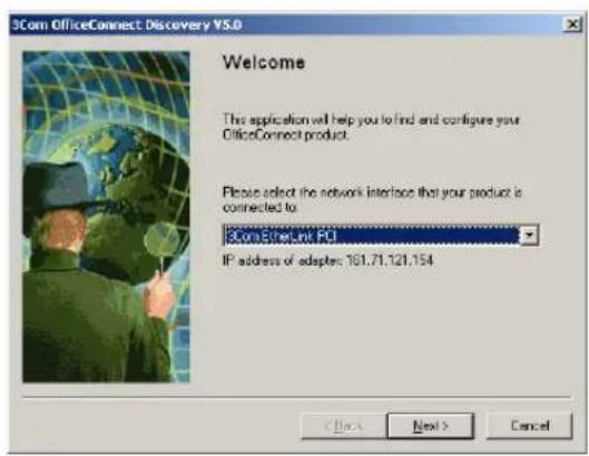
2 When the Welcome screen is displayed click on Next and wait until the application discovers the Routers connected to your LAN.
Figure 83 Discovered Router Screen
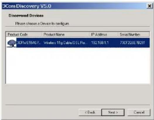
3 Figure 84 shows an example Discovered Devices screen. Highlight the Cable/DSL Router by clicking on it, and press Next.
Figure 84 Discovery Finish Screen
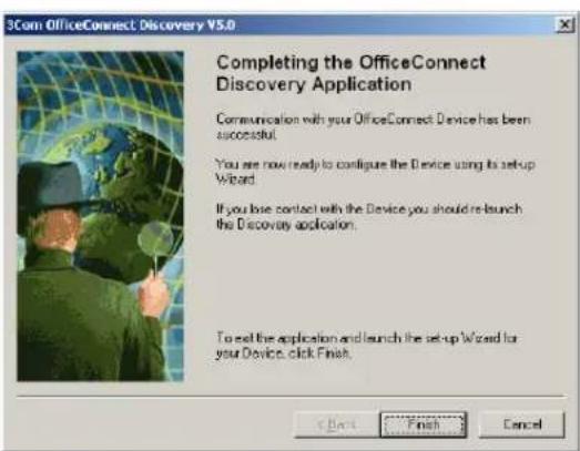
4 Click on Finish to launch a web browser and display the login page for the Router.
B
IP ADDRESSING
| The Internet Protocol Suite | The Internet protocol suite consists of a well-defined set of communications protocols and several standard application protocols. Transmission Control Protocol/Internet Protocol (TCP/IP) is probably the most widely known and is a combination of two of the protocols (IP and TCP) working together. TCP/IP is an internationally adopted and supported networking standard that provides connectivity between equipment from many vendors over a wide variety of networking technologies. |
| Managing the Router over the Network | To manage a device over the network, the Router must be correctly configured with the following IP information:■An IP address■A Subnet Mask |
| IP Addresses and Subnet Masks | Each device on your network must have a unique IP address to operate correctly. An IP address identifies the address of the device to which data is being sent and the address of the destination network. IP addresses have the format n.n.n.x where n is a decimal number between 0 and 255 and x is a number between 1 and 254 inclusive.However, an IP Address alone is not enough to make your device operate. In addition to the IP address, you need to set a subnet mask. All networks are divided into smaller sub-networks and a subnet mask is a number that enables a device to identify the sub-network to which it is connected. |
For your network to work correctly, all devices on the network must have:
■The same sub-network address.
■The same subnet mask.

The only value that will be different is the specific host device number. This value must always be unique.
An example IP address is '192.168.100.8'. However, the size of the network determines the structure of this IP Address. In using the Router, you will probably only encounter two types of IP Address and subnet mask structures.
Type One
In a small network, the IP address of '192.168.100.8' is split into two parts:
■ Part one ('192.168.100') identifies the network on which the device resides.
■Part two ('.8') identifies the device within the network.
This type of IP Address operates on a subnet mask of '255.255.255.0'.
See Table4 for an example about how a network with three computers and a Router might be configured.
Table 4 IP Addressing and Subnet Masking
| Device IP Address Subnet Mask |
| PC 1 192.168.100.8 255.255.255.0 |
| PC 2 192.168.100.33 255.255.255.0 |
| PC 3 192.168.100.188 255.255.255.0 |
| Router 192.168.100.72 255.255.255.0 |
Type Two
In larger networks, where there are more devices, the IP address of '192.168.100.8' is, again, split into two parts but is structured differently:
■Part one ('192.168') identifies the network on which the device resides.
■ Part two ('.100.8') identifies the device within the network.
This type of IP Address operates on a subnet mask of '255.255.0.0'.
See Table5 for an example about how a network (only four computers represented) and a Router might be configured.
Table 5 IP Addressing and Subnet Masking
| Device IP Address Subnet Mask |
| PC 1 192.168.100.8 255.255.0.0 |
| PC 2 192.168.201.30 255.255.0.0 |
| PC 3 192.168.113.155 255.255.0.0 |
| PC 4 192.168.002.230 255.255.0.0 |
| Router 192.168.002.72 255.255.0.0 |
How does a Device Obtain an IP Address and Subnet Mask?
There are three different ways to obtain an IP address and the subnet mask. These are:
■Dynamic Host Configuration Protocol (DHCP) Addressing
■Static Addressing
■Automatic Addressing (Auto-IP Addressing)
DHCP Addressing
The Router contains a DHCP server, which allows computers on your network to obtain an IP address and subnet mask automatically. DHCP assigns a temporary IP address and subnet mask which gets reallocated once you disconnect from the network.
DHCP will work on any client Operating System such as Windows ^® 95, Windows 98 or Windows NT 4.0. Also, using DHCP means that the same IP address and subnet mask will never be duplicated for devices on the network. DHCP is particularly useful for networks with large numbers of users on them.
Static Addressing
You must enter an IP Address and the subnet mask manually on every device. Using a static IP and subnet mask means the address is permanently fixed.
Auto-IP Addressing
Network devices use automatic IP addressing if they are configured to acquire an address using DHCP but are unable to contact a DHCP server. Automatic IP addressing is a scheme where devices allocate themselves
an IP address at random from the industry standard subnet of 169.254.x.x (with a subnet mask of 255.255.0.0). If two devices allocate themselves the same address, the conflict is detected and one of the devices allocates itself a new address.
Automatic IP addressing support was introduced by Microsoft in the Windows 98 operating system and is also supported in Windows 2000.
C
TECHNICAL SPECIFICATIONS
This section lists the technical specifications for the OfficeConnect Wireless 11g Cable/DSL Router.
Wireless 11g Cable/DSL Router
Interfaces
Cable/DSL modem connection — 10Mbps/100Mbps dual speed Ethernet port (10BASE-T/100BASE-TX)
LAN connection — four 10Mbps/100Mbps dual speed Ethernet ports (10BASE-T/100BASE-TX)
WLAN Interfaces
Standard IEEE 802.11g, Direct Sequence Spread Spectrum (DSSS)
Transmission rate: 54Mbps, automatic fallback to 48, 36, 24, 18, 12, or 6 Mbps
Maximum channels: 14
Range up to 304.8m (1000ft)
Frequency: (US/Canada/Europe) 2.400-2.4835 GHz
Sensitivity: 6, 12, 18, 24, 36, 48 Mbps: -85 dBm; 54 Mbps -66 dBm typical
Modulation: CCK, BPSK, QPSK, OFDM
Encryption: 40/64 bit WEP, 128 bit WEP, WPA
Maximum clients: 128
O/P Power: 18dBm
Standard IEEE 802.11b, Direct Sequence Spread Spectrum (DSSS)
Transmission rate: 11bps, automatic fallback to 5.5, 2, or 1 Mbps
Maximum channels: 14
Range up to 304.8m (1000ft)
Frequency: (US/Canada/Europe) 2.400-2.4835 GHz
Sensitivity: 1, 2, 5.5 Mbps: -85 dBm; 11 Mbps -82 dBm typical
Modulation: CCK, BPSK, QPSK, OFDM
Encryption: 40/64 bit WEP, 128 bit WEP, WPA
Maximum clients: 128
O/P Power 18dBm
Operating Temperature
0 °C to 40 °C (32 °F to 105 °F)
Power
7VA, 23.9 BThU/hr
Humidity
0% to 90% (non-condensing) humidity
Dimensions
■Width = 220 mm (8.7 in.)
■Depth = 135 mm (5.3 in.)
■Height = 24 mm (1 in.)
Weight
Approximately 500 g (1.1 lbs)
Standards Functional: ISO 8802/3
IEEE 802.3
IEEE 802.11b, 802.11g, Wi-Fi
Safety: UL60950
CSA 22.2 #60950
IEC 60950
EN 60950
EMC: EN 55022 Class B
EN 55024
CISPR 22
FCC Part 15 Class B*
ICES-003 Class B
CNS 13438 Class A
ETSI EN 301 489–17
Radio CFR 47 FCC Part 15.207, 15.209, 15.247 and 15.249.
ETS 300 328 (2.4 GHz ISM band wide band transmission
systems.
RSS-210
Environmental: EN 60068 (IEC 68)
*See "FCC Statement" on page 140 for conditions of operation.
System Requirements Operating Systems
The Router will support the following Operating Systems:
■Windows 95/98
■Windows NT 4.0
■Windows ME
■Windows 2000
■Windows XP
■Mac OS 8.5 or higher
■Unix
Ethernet Performance
The Router complies to the IEEE 802.3i, u and x specifications.
Wireless Performance
The Router has been designed to conform to the Wi-Fi interoperability test standard.

The Standard for Wireless Fidelity.
Cable Specifications The Router supports the following cable types and maximum lengths:
■Category 3 (Ethernet) or Category 5 (Fast Ethernet or Dual Speed Ethernet) Twisted Pair — shielded and unshielded cable types.
■Maximum cable length of 100m (327.86 ft).
D
SAFETY INFORMATION
Important Safety Information

WARNING: Warnings contain directions that you must follow for your personal safety. Follow all directions carefully.
You must read the following safety information carefully before you install or remove the unit:

WARNING: The Router generates and uses radio frequency (rf) energy. In some environments, the use of rf energy is not permitted. The user should seek local advice on whether or not rf energy is permitted within the area of intended use.

WARNING: Exceptional care must be taken during installation and removal of the unit.

WARNING: Only stack the Router with other OfficeConnect units.

WARNING: To ensure compliance with international safety standards, only use the power adapter that is supplied with the unit.

WARNING: The socket outlet must be near to the unit and easily accessible. You can only remove power from the unit by disconnecting the power cord from the outlet.

WARNING: This unit operates under SELV (Safety Extra Low Voltage) conditions according to IEC 60950. The conditions are only maintained if the equipment to which it is connected also operates under SELV conditions.

WARNING: There are no user-replaceable fuses or user-serviceable parts inside the Router. If you have a physical problem with the unit that cannot be solved with problem solving actions in this guide, contact your supplier.

WARNING: Disconnect the power adapter before moving the unit.
WARNING: RJ-45 ports. These are shielded RJ-45 data sockets. They cannot be used as telephone sockets. Only connect RJ-45 data connectors to these sockets.
YOU SHOULD CAREFULLY READ THE FOLLOWING TERMS AND CONDITIONS BEFORE DOWNLOADING, INSTALLING AND USING THIS PRODUCT, THE USE OF WHICH IS LICENSED BY 3COM CORPORATION (i3COMi) TO ITS CUSTOMERS FOR THEIR USE ONLY AS SET FORTH BELOW. DOWNLOADING, INSTALLING OR OTHERWISE USING ANY PART OF THE SOFTWARE OR DOCUMENTATION INDICATES THAT YOU ACCEPT THESE TERMS AND CONDITIONS. IF YOU DO NOT AGREE TO THE TERMS AND CONDITIONS OF THIS AGREEMENT, DO NOT DOWNLOAD, INSTALL OR OTHERWISE USE THE SOFTWARE OR DOCUMENTATION, DO NOT CLICK ON THE "I AGREE" OR SIMILAR BUTTON. AND IF YOU HAVE RECEIVED THE SOFTWARE AND DOCUMENTATION ON PHYSICAL MEDIA, RETURN THE ENTIRE PRODUCT WITH THE SOFTWARE AND DOCUMENTATION UNUSED TO THE SUPPLIER WHERE YOU OBTAINED IT.
LICENSE: 3Com grants you a nonexclusive, nontransferable (except as specified herein) license to use the accompanying software program(s) in executable form (the iSoftware) and accompanying documentation (the iDocumentation), subject to the terms and restrictions set forth in this Agreement. You are not permitted to lease, rent, distribute or sublicense (except as specified herein) the Software or Documentation or to use the Software or Documentation in a time-sharing arrangement or in any other unauthorized manner. Further, no license is granted to you in the human readable code of the Software (source code). Except as provided below, this Agreement does not grant you any rights to patents, copyrights, trade secrets, trademarks, or any other rights with respect to the Software or Documentation.
Subject to the restrictions set forth herein, the Software is licensed to be used on any workstation or any network server owned by or leased to you, for your internal use, provided that the Software is used only in connection with this 3Com product. You may reproduce and provide one (1) copy of the Software and Documentation for each such workstation or network server on which the Software is used as permitted hereunder. Otherwise, the Software and Documentation may be copied only as essential for backup or archive purposes in support of your use of the Software as permitted hereunder. Each copy of the Software and Documentation must contain 3Com's and its licensors' proprietary rights and copyright notices in the same form as on the original. You agree not to remove or deface any portion of any legend provided on any licensed program or documentation delivered to you under this Agreement.
ASSIGNMENT; NO REVERSE ENGINEERING: You may transfer the Software, Documentation and the licenses granted herein to another party in the same country in which you obtained the Software and Documentation if the other party agrees in writing to accept and be bound by the terms and conditions of this Agreement. If you transfer the Software and Documentation, you must at the same time either transfer all copies of the Software and Documentation to the party or you must destroy any copies not transferred. Except as set forth above, you may not assign or transfer your rights under this Agreement.
Modification, reverse engineering, reverse compiling, or disassembly of the Software is expressly prohibited. However, if you are a European Union (iEUi) resident, information necessary to achieve interoperability of the Software with other programs within the meaning of the EU Directive on the Legal Protection of Computer Programs is available to you from 3Com upon written request.
EXPORT: This product, Software and/or technical data (collectively "Product") may contain encryption. This Product is subject to U.S. and EU export control laws and regulations and may be subject to export or import regulations in other countries, including controls on encryption products. You agree that you will not export, reexport or transfer the Product (or any copies thereof) or any products utilizing the Product in violation of any applicable laws or regulations of the United States or the country where you legally obtained it. You are responsible for obtaining any licenses to export, reexport, transfer or import the Product.
In addition to the above, the Product may not be used by, or exported or reexported to (i) any U.S.- or EU- sanctioned or embargoed country, or to nationals or residents of such countries; or (ii) to any person, entity, organization or other party identified on the U.S. Department of Commerce's Table of Denial Orders or the U.S. Department of Treasury's lists of "Specially Designated Nationals and Blocked Persons," as published and revised from time to time; (iii) to any party engaged in nuclear, chemical/biological weapons or missile proliferation activities, unless authorized by U.S. and local (as required) law or regulations.
TRADE SECRETS; TITLE: You acknowledge and agree that the structure, sequence and organization of the Software are the valuable trade secrets of
3Com and its suppliers. You agree to hold such trade secrets in confidence. You further acknowledge and agree that ownership of, and title to, the Software and Documentation and all subsequent copies thereof regardless of the form or media are held by 3Com and its suppliers.
UNITED STATES GOVERNMENT LEGENDS: The Software, Documentation and any other technical data provided hereunder is commercial in nature and developed solely at private expense. The Software is delivered as iCommercial Computer Software as defined in DFARS 252.227-7014 (June 1995) or as a commercial item as defined in FAR 2.101(a) and as such is provided with only such rights as are provided in this Agreement, which is 3Com's standard commercial license for the Software. Technical data is provided with limited rights only as provided in DFAR 252.227-7015 (Nov. 1995) or FAR 52.227-14 (June 1987), whichever is applicable.
TERM AND TERMINATION: The licenses granted hereunder are perpetual unless terminated earlier as specified below. You may terminate the licenses and this Agreement at any time by destroying the Software and Documentation together with all copies and merged portions in any form. The licenses and this Agreement will also terminate immediately if you fail to comply with any term or condition of this Agreement. Upon such termination you agree to destroy the Software and Documentation, together with all copies and merged portions in any form.
LIMITED WARRANTIES AND LIMITATION OF LIABILITY: All warranties and limitations of liability applicable to the Software are as stated on the Limited Warranty Card or in the product manual, whether in paper or electronic form, accompanying the Software. Such warranties and limitations of liability are incorporated herein in their entirety by this reference.
GOVERNING LAW: This Agreement shall be governed by the laws of the State of California, U.S.A. excluding its conflicts of laws principles and excluding the United Nations Convention on Contracts for the International Sale of Goods.
SEVERABILITY: In the event any provision of this Agreement is found to be invalid, illegal or unenforceable, the validity, legality and enforceability of any of the remaining provisions shall not in any way be affected or impaired and a valid, legal and enforceable provision of similar intent and economic impact shall be substituted therefor.
ENTIRE AGREEMENT: This Agreement sets forth the entire understanding and agreement between you and 3Com and supersedes all prior agreements, whether written or oral, with respect to the Software and Documentation, and may be amended only in a writing signed by both parties. Should you have any questions concerning this Agreement or if you desire to contact 3Com for any reason, please contact the 3Com subsidiary serving your country, or write: 3Com Corporation, Customer Support Information, 350 Campus Drive, Marlborough, MA 01752-3064
3Com Corporation
350 Campus Drive,
Marlborough, MA 01752-3064
Copyright © 2004 3Com Corporation and its licensors. All rights reserved. 3Com is a registered trademark of 3Com Corporation.
F
ISP INFORMATION
Information Regarding Popular ISPs
| WAN Types Characteristics Popular ISPs | ||
| Dynamic IP (Clone MAC) | Cable modem ISP, non-hostname based. Need to clone the MAC address in the Advanced tab of the Internet Settings page. | MediaOne, RoadRunner, Optimum Online, Time Warner, Charter, Adelphia, Metrocast. |
| Dynamic IP (Hostname) | Cable ISP, Requires Hostname to authenticate ie. cx213818-B. Need to enter the hostname in the Internet Settings page. | @Home Network, Cogoco, ComCast, Cox, Excite, Rogers, Shaw, Insight, Videotron |
| PPPoE (DSL) | Usually special software installed on PC, MacPOET/WinPOET, EnterNet 300. The Router has this software built in and you can remove it from your PC. You will need to enter the user name and password that your ISP provided to you in the PPPoE page of the Router. Leave the service name blank unless your ISP requires it. | Bell*, Century Tel, Citizens, Primus, Prodigy, Snet, Sprint FC, Verizon, First World, Brightnet, Earthlink, Ameritech, Covad, Mindspring, Sympatico DSL, USwest, Owest, SNet |
| PPTP Cable or DSL, always on. Some European ISPs require a PPTP tunnel to authenticate their network. | KPN (Netherlands), Austria Telecom | |
| Static (DSL) | DSL Modem, always on. Need to enter ALL IP information from ISP in the Static IP address section of the Internet Settings page. | CableSpeed, Cnet, Direct Link, Drizzle, DSL Extreme, Earthlink Wireless, Fast Point, Flashcom, GTE-WhirlWind, Heavenet, HSA Corp, I-55, InterAccess, LinkLine, Mission, Nauticom, NAS, Omitel, Onterra, Phatpipe, Rhythms, Speakeasy, Sterling, XO, Zyan |
| Static (Cable) | Cable Modem, Always on, ISP assigns specific IP information which needs to be entered on the “Fixed IP” page of the Router. | Cox Cable, Sprint, US Cable, Cable-Cable |
*Bell includes Bell Advantage, Bell Canada, Bell South, PacBell and Southwestern Bell.
GLOSSARY
802.11b The IEEE specification for wireless Ethernet which allows speeds of up to 11 Mbps. The standard provides for 1, 2, 5.5 and 11 Mbps data rates. The rates will switch automatically depending on range and environment.
802.11g The IEEE specification for wireless Ethernet which allows speeds of up to 54 Mbps. The standard provides for 6, 12, 24, 36, 48 and 54 Mbps data rates. The rates will switch automatically depending on range and environment.
10BASE-T The IEEE specification for 10 Mbps Ethernet over Category 3, 4 or 5 twisted pair cable.
100BASE-TX The IEEE specification for 100 Mbps Fast Ethernet over Category 5 twisted-pair cable.
Access Point An Access Point is a device through which wireless clients connect to other wireless clients and which acts as a bridge between wireless clients and a wired network, such as Ethernet. Wireless clients can be moved anywhere within the coverage area of the access point and still connect with each other. If connected to an Ethernet network, the access point monitors Ethernet traffic and forwards appropriate Ethernet messages to the wireless network, while also monitoring wireless client radio traffic and forwarding wireless client messages to the Ethernet LAN.
Ad Hoc mode Ad Hoc mode is a configuration supported by most wireless clients. It is used to connect a peer to peer network together without the use of an access point. It offers lower performance than infrastructure mode, which is the mode the Router uses. (see also Infrastructure mode.)
Auto-negotiation Some devices in the OfficeConnect range support auto-negotiation. Auto-negotiation is where two devices sharing a link, automatically
configure to use the best common speed. The order of preference (best first) is: 100BASE-TX full duplex, 100BASE-TX half duplex, 10BASE-T full duplex, and 10BASE-T half duplex. Auto-negotiation is defined in the IEEE 802.3 standard for Ethernet and is an operation that takes place in a few milliseconds.
Bandwidth The information capacity, measured in bits per second, that a channel can transmit. The bandwidth of Ethernet is 10 Mbps, the bandwidth of Fast Ethernet is 100 Mbps. The bandwidth for 802.11b wireless is 11Mbps.
Category 3 Cables One of five grades of Twisted Pair (TP) cabling defined by the EIA/TIA-586 standard. Category 3 is voice grade cable and can only be used in Ethernet networks (10BASE-T) to transmit data at speeds of up to 10 Mbps.
Category 5 Cables One of five grades of Twisted Pair (TP) cabling defined by the EIA/TIA-586 standard. Category 5 can be used in Ethernet (10BASE-T) and Fast Ethernet networks (100BASE-TX) and can transmit data up to speeds of 100 Mbps. Category 5 cabling is better to use for network cabling than Category 3, because it supports both Ethernet (10 Mbps) and Fast Ethernet (100 Mbps) speeds.
Channel Similar to any radio device, the OfficeConnect Cable/DSL Router allows you to choose different radio channels in the wireless spectrum. A channel is a particular frequency within the 2.4GHz spectrum within which the Router operates.
Client The term used to describe the desktop PC that is connected to your network.
DDNS Dynamic Domain Name Server. A method that enables Internet users to tie their domain name(s) to computers or servers. DDNS enables a domain name to follow an IP address automatically when the IP address changes.
DHCP Dynamic Host Configuration Protocol. This protocol automatically assigns an IP address for every computer on your network. Windows 95, Windows 98 and Windows NT 4.0 contain software that assigns IP addresses to workstations on a network. These assignments are made by the DHCP server software that runs on Windows NT Server, and Windows
95 and Windows 98 will call the server to obtain the address. Windows 98 will allocate itself an address if no DHCP server can be found.
DNS Server Address
DNS stands for Domain Name System, which allows Internet host computers to have a domain name (such as 3com.com) and one or more IP addresses (such as 192.34.45.8). A DNS server keeps a database of host computers and their respective domain names and IP addresses, so that when a domain name is requested (as in typing "3com.com" into your Internet browser), the user is sent to the proper IP address. The DNS server address used by the computers on your home network is the location of the DNS server your ISP has assigned.
DSL modem DSL stands for digital subscriber line. A DSL modem uses your existing phone lines to send and receive data at high speeds.
Encryption
A method for providing a level of security to wireless data transmissions. The OfficeConnect Cable/DSL Router and Wireless Cable/DSL Router offer a choice of encryption methods. See "WPA" and "WEP" for details.
ESSID Extended Service Set Identifier. The ESSID is a unique identifier for your wireless network. You must have the same ESSID entered into the Router and each of it's wireless clients.
Ethernet
A LAN specification developed jointly by Xerox, Intel and Digital Equipment Corporation. Ethernet networks use CSMA/CD to transmit packets at a rate of 10 Mbps over a variety of cables.
Ethernet Address See MAC address.
Fast Ethernet An Ethernet system that is designed to operate at 100 Mbps.
Firewall Electronic protection that prevents anyone outside of your network from seeing your files or damaging your computers.
Full Duplex
A system that allows packets to be transmitted and received at the same time and, in effect, doubles the potential throughput of a link.
Router A device that acts as a central hub by connecting to each computer's network interface card and managing the data traffic between the local network and the Internet.
Half Duplex A system that allows packets to transmitted and received, but not at the same time. Contrast with full duplex.
Hub A device that regenerates LAN traffic so that the transmission distance of that signal can be extended. Hubs are similar to repeaters, in that they connect LANs of the same type; however they connect more LANs than a repeater and are generally more sophisticated.
IEEE Institute of Electrical and Electronics Engineers. This American organization was founded in 1963 and sets standards for computers and communications.
IETF Internet Engineering Task Force. An organization responsible for providing engineering solutions for TCP/IP networks. In the network management area, this group is responsible for the development of the SNMP protocol.
Infrastructure mode Infrastructure mode is the wireless configuration supported by the Router. You will need to ensure all of your clients are set up to use infrastructure mode in order for them to communicate with the Access Point built into your Router. (see also Ad Hoc mode)
IP Internet Protocol. IP is a layer 3 network protocol that is the standard for sending data through a network. IP is part of the TCP/IP set of protocols that describe the routing of packets to addressed devices. An IP address consists of 32 bits divided into two or three fields: a network number and a host number or a network number, a subnet number, and a host number.
IP Address Internet Protocol Address. A unique identifier for a device attached to a network using TCP/IP. The address is written as four octets separated with periods (full-stops), and is made up of a network section, an optional subnet section and a host section.
ISP Internet Service Provider. An ISP is a business that provides connectivity to the Internet for individuals and other businesses or organizations.
LAN Local Area Network. A network of end stations (such as PCs, printers, servers) and network devices (hubs and switches) that cover a relatively small geographic area (usually not larger than a floor or building). LANs are characterized by high transmission speeds over short distances (up to 1000 metres).
MAC Media Access Control. A protocol specified by the IEEE for determining which devices have access to a network at any one time.
MAC Address Media Access Control Address. Also called the hardware or physical address. A layer 2 address associated with a particular network device. Most devices that connect to a LAN have a MAC address assigned to them as they are used to identify other devices in a network. MAC addresses are 6 bytes long.
NAT Network Address Translation. NAT enables all the computers on your network to share one IP address. The NAT capability of the Router allows you to access the Internet from any computer on your home network without having to purchase more IP addresses from your ISP.
Network A Network is a collection of computers and other computer equipment that are connected for the purpose of exchanging information or sharing resources. Networks vary in size, some are within a single room, others span continents.
Network Interface Card (NIC) A circuit board installed into a piece of computing equipment, for example, a computer, that enables you to connect it to the network. A NIC is also known as an adapter or adapter card.
Protocol A set of rules for communication between devices on a network. The rules dictate format, timing, sequencing and error control.
PPPoE Point-to-Point Protocol over Ethernet. Point-to-Point Protocol is a method of data transmission originally created for dial-up connections; PPPoE is for Ethernet connections.
PPTP Point-to-Point Tunneling Protocol is a method of secure data transmission between two remote sites over the internet.
RIP Routing Information Protocol. RIP allows an administrator to set up routing information on one RIP enabled device, and have that routing information replicated to all RIP enabled devices on the network.
RJ-45 A standard connector used to connect Ethernet networks. The "RJ" stands for "registered jack".
Server A computer in a network that is shared by multiple end stations. Servers provide end stations with access to shared network services such as computer files and printer queues.
SPI Stateful Packet Inspection. This feature requires the firewall to remember what outgoing requests have been sent and only allow responses to those requests back through the firewall. This way, un-requested attempts to access the network will be denied.
SSID Service Set Identifier. Some vendors of wireless products use SSID interchangeably with ESSID.
Subnet Address An extension of the IP addressing scheme that allows a site to use a single IP network address for multiple physical networks.
Subnet mask A subnet mask, which may be a part of the TCP/IP information provided by your ISP, is a set of four numbers configured like an IP address. It is used to create IP address numbers used only within a particular network (as opposed to valid IP address numbers recognized by the Internet, which must assigned by InterNIC).
Subnets A network that is a component of a larger network.
Switch A device that interconnects several LANs to form a single logical LAN that comprises of several LAN segments. Switches are similar to bridges, in that they connect LANs of a different type; however they connect more LANs than a bridge and are generally more sophisticated.
TCP/IP Transmission Control Protocol/Internet Protocol. This is the name for two of the most well-known protocols developed for the interconnection of networks. Originally a UNIX standard, TCP/IP is now supported on almost all platforms, and is the protocol of the Internet.
TCP relates to the content of the data travelling through a network — ensuring that the information sent arrives in one piece when it reaches its destination. IP relates to the address of the end station to which data is being sent, as well as the address of the destination network.
Traffic The movement of data packets on a network.
universal plug and play Universal plug and play is a system which allows compatible applications to read some of their settings from the Router. This allows them to automatically configure some, or all, of their settings and need less user configuration.
URL Filter A URL Filter is a feature of a firewall that allows it to stop its clients form browsing inappropriate Web sites.
WAN Wide Area Network. A network that connects computers located in geographically separate areas (for example, different buildings, cities, or countries). The Internet is an example of a wide area network.
WDS Wireless Distribution System. A system that can be comprised of a bridging and/or a repeater mode. In wireless bridging, APs communicate only with each other to bridge together two separate networks. In wireless repeating, APs rebroadcast received signals to extend reach and range, at the expense of throughput. The Router uses wireless repeating.
WECA Wireless Ethernet Compatibility Alliance. An industry group formed to certify cross vendor interoperability and compatibility of 802.11b and 802.11g wireless networking products and to promote the standard for enterprise, small business and home environments. (see also 802.11b, 802.11g, Wi-Fi)
WEP Wired Equivalent Privacy. A shared key encryption mechanism for wireless networking. Encryption strength is 40/64 bit or 128 bit.
Wi-Fi Wireless Fidelity. This is the certification granted by WECA to products that meet their interoperability criteria. (see also 802.11b, WECA)
Wireless Client The term used to describe a desktop or mobile PC that is wirelessly connected to your wireless network
Wireless LAN Service Area Another term for ESSID (Extended Service Set Identifier)
Wizard A Windows application that automates a procedure such as installation or configuration.
WLAN Wireless Local Area Network. A WLAN is a group of computers and devices connected together by wireless in a relatively small area (such as a house or office).
WPA Wi-Fi Protected Access. A dynamically changing encryption mechanism for wireless networking. Encryption strength is 256 bit.
INDEX
A
Access Rights 79
Addresses
IP 113
Administration Password 32, 47
Advanced 91
DDNS 94
RIP 92
routing table 94
security 96
static route 91
Automatic Addressing 115
C
Cable Specifications 119
Channels 139
Clone MAC address 68
Configuration
backup 89
restore 90
Connection Policy 86
content filtering 83
Conventions
notice icons, About This Guide 8
text, About This Guide 8
Country Selection 30
D
DDNS 94, 96
DHCP 35, 40, 49, 115
DHCP Server 27
Discovery Application 111
DMZ 73
DNS 26, 37, 39, 68, 69, 71, 72
primary 37, 39, 67
secondary 37, 39, 67
DoS attacks 84
DOS detect criteria
configuring 87
Dynamic 65
Dynamic IP Address 35, 65, 73
dynamic IP address 65
E
encryption 54
WEP 54
WPA 54
F
Firewall 73
Intrustion Detection 85
SPI 84
Forgotten Password 105
|
Internet
addresses 113
Internet Addressing Mode 33
Internet Settings 65
dynamic IP address 65
L2TP 66
PPPoE 65
PPTP 66
static IP address 65
Intrusion Detection 85
IP Address 22, 36, 40, 49, 113
IP Allocation 66
ISP Connection 66
ISP Gateway Address 37
L
L2TP 66, 72
LAN 40, 48
LED 14
Login 112
Logs 100
M
MAC Address 36, 50
deleting 62
modifying 62
N
Network
addresses 113
Networking
wireless 105
NIC
wireless 14
Nitro Mode 54
P
Password 29, 47
PC Privileges 77
PING 97
PPPoE 21, 28, 34, 65, 69
PPTP 21, 66, 70
Profile 64
R
Remote Administration 97
Reset to Factory Defaults 90, 105
Restart 88
RIP 92
setting up 92
routing table 94
s
Safety Information 19
security
advanced settings 96
remote administration 97
Setup Wizard 29, 48
Special Applications 75
Specifications
technical 117
SPI 84
Static Addressing 115
Static IP Address 65, 67
static IP address 65
static route 91
Status 98
Subnet Mask 36, 40, 113
Summary 42
Support Information 100
Support Links 101
T
TCP/IP 25, 27, 40, 113
Technical
specifications 117
standards 117
Time Zone 33, 88
U
Unit Configuration 48
Upgrade 90
URL Filter 80
V
Virtual Servers 73, 74
W
WAN 33
WDS 63
Web Proxy 28
Wireless
authorized PCs 61
channel selection 52
client list 62
configuration 52
connection control 60
encryption 54
LED 15
networking 105
NIC 14
service area name 53
settings 41, 51
WPA encryption
configuring 54
enterprise mode 55
REGULATORY NOTICES FOR THE WIRELESS 11G CABLE/DSL ROUTER
Channels Use of the Wireless 11g Cable/DSL Router is only authorized for the
channels approved by each country. For proper installation, login to the management interface and select your country from the drop down list.
Table 5 below details the channels permitted by the local regulatory agencies:

Channel Configuration is only available on the 3CRWE554G72T unit. The 3CRWE554G72TU unit is for use in the US, and the channel is pre-configured.
Table 5 Channels
| Channels Country | |
| 1 - 13 | Australia, Austria, Bahrain, Belarus, Belgium, Chile, China, Costa Rica, Croatia, Cyprus, Czech Republic, Denmark, Finland, France*, Germany, Greece, Hong Kong, Hungary, Iceland, India, Indonesia, Ireland, Italy, Liechtenstein, Lithuania, Luxembourg, Malaysia, Netherlands, New Zealand, Norway, Paraguay, Peru, Philippines, Poland, Portugal, Russia, Saudi Arabia, Singapore, Slovenia, South Africa, South Korea, Spain, Sweden, Switzerland, Thailand, Turkey, United Kingdom, Uruguay, Venezuela. |
| 1 - 11 Argentina, Brazil, Canada, Columbia, Mexico, Taiwan, United States | |
| 10 - 13 France*, Jordan | |
| 5 - 7 Israel | |
| 1-14 Japan | |
* The channels available for use in France depend on the region in which you are located.
FCC Statement
This equipment has been tested and found to comply with the limits for a Class B digital device, pursuant to Part 15 of the FCC Rules, and the Canadian Department of Communications Equipment Standards entitled, "Digital Apparatus," ICES-003. These limits are designed to provide reasonable protection against harmful interference in a residential installation. This equipment generates, uses and can radiate radio frequency energy and, if not installed and used in accordance with the instructions, may cause harmful interference to radio communications. However, there is no guarantee that interference will not occur in a particular installation. If this equipment does cause harmful interference to radio or television reception, which can be determined by turning the equipment off and on, the user is encouraged to try to correct the interference by one of the following measures:
■Reorient or relocate the receiving antenna.
■ Increase the separation between the equipment and receiver.
■Connect the equipment into an outlet on a circuit different from that to which the receiver is connected.
■ Consult the dealer or an experienced radio/TV technician for help.
This device complies with Part 15 of the FCC Rules. Operation is subject to the following two conditions: (1) This device may not cause harmful interference, and (2) this device must accept any interference received, including interference that may cause undesired operation.
FCC Caution: Any changes or modifications not expressly approved by the party responsible for compliance could void the user's authority to operate this equipment.
IMPORTANT NOTE: FCC Radiation Exposure Statement:
This equipment complies with FCC radiation exposure limits set forth for an uncontrolled environment. This equipment should be installed and operated with minimum distance 20cm between the radiator and your body.
This transmitter must not be co-located or operating in conjunction with any other antenna or transmitter.
| Information to the User | If this equipment does cause interference to radio or television reception, which can be determined by turning the equipment off and on, the user is encouraged to try to correct the interference by one or more of the following measures:■Reorient the receiving antenna.■Relocate the equipment with respect to the receiver.■Move the equipment away from the receiver.■Plug the equipment into a different outlet so that equipment and receiver are on different branch circuits.■Consult the dealer or an experienced radio/television technician for help.The user may find the following booklet prepared by the Federal Communications Commission helpful:How to Identify and Resolve Radio-TV Interference ProblemsThis booklet is available from the U.S. Government Printing Office, Washington, DC 20402, Stock No. 004-000-00345-4. In order to meet FCC emissions limits, this equipment must be used only with cables which comply with IEEE 802.3. |
| FCC Declaration of Conformity | We declare under our sole responsibility that theModel: Description:3CRWE554G72T Wireless 11g Cable/DSL Router3CRWE554G72TU Wireless 11g Cable/DSL Router (US)to which this declaration relates, is in conformity with the following standards or other normative documents:■ANSI C63.4-1992 Methods of Measurement■Federal Communications Commission 47 CFR Part 15, subpart B 15.107 (a)Class B Conducted Limits15.109 (a)Class B Radiated Emissions Limits■15.107 (e)Class B Conducted Limits15.109 (g)Class B Radiated Emissions LimitsExposure to Radio Frequency Radiation: The radiated output power of the 3Com OfficeConnect Wireless 11g Cable/DSL Router is far below the FCC radio frequency exposure limits. Nevertheless, the 3Com OfficeConnect Wireless 11g Cable/DSL Router shall be used in such manner that the potential for human contact during normal operation is minimized. The distance between the antennas and the user should not be less than 20 cm. |
| CE Statement (Europe) | This product complies with the European Low Voltage Directive 73/23/EEC, EMC Directive 89/336/EEC as amended by European Directive 93/68/EEC and the Radio and Telecommunications Terminal Equipment Directive 99/5/EC. |
| CSA Statement | This Class B digital apparatus meets all requirements of the Canadian Interference-Causing Equipment Regulations.Cet appareil numérique de la classe B respecte toutes les exigences du Règlement sur le matériel brouilleur du Canada. |
| BSMI Statement | 警告使用者:這是甲類的資訊產品,在居住的環境中使用時,可能會造成射頻干擾,在這種情況下,使用者會被要求採取某些適當的對策。 |
FCC  | CAUTION: To assure continued compliance, any changes or modifications not expressly approved by the party responsible for compliance could void the user's authority to operate this equipment. |
RF Exposure Compliance Statement (U.S.)  | CAUTION: The 3Com OfficeConnect Cable/DSL Router has been certified as a mobile computing device as per FCC Section 2.1091. In order to comply with the FCC RF exposure requirements, the 3Com OfficeConnect Cable/DSL Router must only be installed with approved antennas and a minimum separation distance of 20 cm (8 in) must be maintained from the antenna to any nearby persons. |
RF Exposure Compliance Statement (U.S.)
Potential RF Interference (Canada)

CAUTION: To prevent radio interference to the licensed service, this device is intended to be operated indoors and away from windows to provide maximum shielding. Equipment (or it's transmit antenna) that is installed outdoors is subject to licensing.
Industry Canada - Class B
This digital apparatus does not exceed the Class B limits for radio noise emissions from digital apparatus as set out in the interference-causing equipment standard entitled “Digital Apparatus,” ICES-003 of Industry Canada.
3Com Corporation, Corporate Headquarters, 350 Campus Drive, Marlborough, MA USA 01752-3064.
To learn more about 3Com products and services, visit our World Wide Web site at www.3com.com
All specifications are subject to change without notice.
Copyright © 2004 3Com Corporation. All rights reserved. 3Com and OfficeConnect are registered trademarks of 3Com Corporation. All other company and product names may be trademarks of their respective companies.
DUA0554-TAAA02

3com
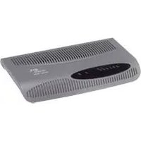
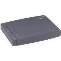
- 3Com Corporation 350 Campus Drive Marlborough, MA USA 01752-3064
- UNITED STATES GOVERNMENT LEGEND
- ENVIRONMENTAL STATEMENT
- End of Life Statement
- Regulated Materials Statement
- Environmental Statement about the Documentation
- CONTENTS
- ABOUT THIS GUIDE
- INTRODUCING THE ROUTER
- HARDWARE INSTALLATION
- SETTING UP YOUR COMPUTERS
- RUNNING THE SETUP WIZARD
- ROUTER CONFIGURATION
- TROUBLESHOOTING
- A USING DISCOVERY
- B IP ADDRESSING
- C TECHNICAL SPECIFICATIONS
- D SAFETY INFORMATION
- E END USER SOFTWARE LICENSE AGREEMENT
- F ISP INFORMATION
- REGULATORY NOTICES FOR THE WIRELESS 11G CABLE/DSL ROUTER
- Naming Convention
- Conventions
- Feedback about this User Guide
- pddtechpubs\_comments@3com.com
- Related Documentation
- OfficeConnect Wireless 11g Cable/DSL Router
- Router Advantages The advantages of the Router include:
- Package Contents The Router kit includes the following items:
- Alert LED
- Power LED
- Wireless LAN (WLAN) Status LED
- Four LAN Status LEDs
- Cable/DSL Status LED
- Rear Panel
- Power Adapter Socket
- Power Adapter OK LED
- Ethernet Cable/DSL port
- Four 10/100 LAN ports
- 2
- HARDWARE INSTALLATION
- Using the Rubber Feet
- Stacking the Router
- Wall Mounting
- Before you Install your Router
- Powering Up the Router
- Connecting the Router
- 3
- SETTING UP YOUR COMPUTERS
- Obtaining an IP Address Automatically
- Disabling PPPoE and PPTP Client Software
- Disabling Web Proxy
- 4
- RUNNING THE SETUP WIZARD
- Accessing the Wizard
- PPPoE Mode
- Dynamic IP Address Mode
- Static IP Mode
- PPTP Mode
- L2TP Mode
- Wireless Settings
- 5
- Main Menu
- Getting Help
- Welcome Screen
- Notice Board
- Password
- Changing the Administration Password
- DHCP Clients List
- Adding Fixed DHCP Mappings
- Configuration
- Enable Wireless Networking
- Channel Selection
- Service Area Name/SSID
- Enable Broadcast SSID
- Device Name
- Nitro Mode
- Configuring WPA Encryption
- Using Enterprise Mode
- Using Manual Pre-Shared Key
- Using Pre-Shared Passphrase
- Configuring WEP Encryption
- Encryption Keys
- Connection Control
- Authorized Wireless PCs
- Modifying a MAC Address
- Deleting a MAC Address
- Client List
- WDS Figure 45 WDS Screen
- ■Service Area Name/SSID of the Router
- ■Encryption settings from the Router
- ■Profile Name
- Internet Settings
- Static IP Address (DSL or Cable)
- Dynamic IP Address (DSL or Cable)
- PPPoE (DSL only)
- PPTP (DSL or Cable)
- L2TP (DSL or Cable)
- Connection to ISP
- Static IP Address
- Dynamic IP Address
- PPP over Ethernet
- PPTP
- L2TP
- Firewall
- Virtual Servers
- Virtual DMZ
- Virtual Server
- Special Applications
- Deny List
- Allow List
- Content Filter
- Intrusion Detection Feature
- Stateful Packet Inspection
- Alert by E-mail
- Connection Policy
- DoS Detect Criteria
- Backup Configuration
- Restore Configuration Data
- Reset to Factory Default
- Upgrade
- Advanced
- Static Route
- Setting Up RIP
- TZO.com
- DynDNS.org
- Using Advanced Settings
- Enabling Remote Administration
- Status and Logs
- Support/Feedback
- Feedback
- 6
- TROUBLESHOOTING
- Basic Connection Checks
- Browsing to the Router Configuration Screens
- Connecting to the Internet
- Forgotten Password and Reset to Factory Defaults
- Wireless Networking
- Power LED or Power Adapter OK LED Not Lit
- Replacement Power Adapters
- Recovering from Corrupted Software
- Frequently Asked Questions
- How do I reset the Router to Factory Defaults?
- A
- USING DISCOVERY
- Running the Discovery Application
- Windows Installation (95/98/2000/Me/NT)
- B
- IP ADDRESSING
- Type One
- Type Two
- How does a Device Obtain an IP Address and Subnet Mask?
- DHCP Addressing
- Static Addressing
- Auto-IP Addressing
- C
- TECHNICAL SPECIFICATIONS
- Wireless 11g Cable/DSL Router
- Interfaces
- WLAN Interfaces
- Operating Temperature
- Power
- Humidity
- Dimensions
- Weight
- System Requirements Operating Systems
- Ethernet Performance
- Wireless Performance
- D
- SAFETY INFORMATION
- Important Safety Information
- F
- ISP INFORMATION
- GLOSSARY
- DNS Server Address
- Encryption
- Ethernet
- Full Duplex
- INDEX
- E
- |
- L
- M
- N
- P
- R
- s
- T
- U
- V
- W
- FCC Statement
- IMPORTANT NOTE: FCC Radiation Exposure Statement:
- RF Exposure Compliance Statement (U.S.)
- Potential RF Interference (Canada)
- Industry Canada - Class B
Brand : 3COM
Model : 3CRWE554G72T OfficeConnect
Category : Router