
Router 3033 - Router 3COM - Free user manual and instructions
Find the device manual for free Router 3033 3COM in PDF.


| Brand | 3Com |
| Model | Router 3033 (3C13683) |
| Product Type | G.SHDSL Router |
| Processor | MPC859 50 MHz |
| SDRAM | 64 MB |
| Flash Memory | 8 MB |
| Dimensions (W x H x D) | 300 mm x 180 mm x 45 mm (11.81 in x 7.1 in x 1.77 in) |
| Weight | 1 kg (2.2 lb) |
| Power Consumption | 12 W maximum |
| Power Supply | External: input 100-240 V AC, 50/60 Hz; output 12 V DC, 4 A |
| Ethernet Ports | 4 x 10/100BASE-T (RJ45) |
| WAN Port | 1 x G.SHDSL (RJ11) |
| Console Port | 1 x RJ45 |
| G.SHDSL Rate | 192 kbps to 2320 kbps symmetric, in steps of 8 kbps |
| Interface Standard | ITU-T G.991.2, G.994.1 handshaking |
| LED Indicators | 8 LEDs: LAN0-3, DSL ACT, DSL LNK, SYS, PWR |
| Operating Temperature | 0°C to 40°C (32°F to 104°F) |
| Operating Humidity | 10% to 90% noncondensing |
| Software Upgrade | Via XModem or Ethernet (TFTP/FTP) |
| Configuration | Command Line Interface (CLI) via console or Telnet |
| Mounting | Desktop; table mount with adequate ventilation |
| Safety Precautions | Use ESD wrist strap; ensure proper grounding; do not hot-swap cables |
| Spare Parts / Repairability | Contact 3Com support for spare parts and RMA authorization |
Frequently Asked Questions - Router 3033 3COM
User questions about Router 3033 3COM
0 question about this device. Answer the ones you know or ask your own.
Ask a new question about this device
Download the instructions for your Router in PDF format for free! Find your manual Router 3033 - 3COM and take your electronic device back in hand. On this page are published all the documents necessary for the use of your device. Router 3033 by 3COM.
USER MANUAL Router 3033 3COM
Copyright © 2004, 3Com Corporation. All rights reserved. No part of this documentation may be reproduced in any form or by any means or used to make any derivative work (such as translation, transformation, or adaptation) without written permission from 3Com Corporation.
3Com Corporation reserves the right to revise this documentation and to make changes in content from time to time without obligation on the part of 3Com Corporation to provide notification of such revision or change.
3Com Corporation provides this documentation without warranty, term, or condition of any kind, either implied or expressed, including, but not limited to, the implied warranties, terms or conditions of merchantability, satisfactory quality, and fitness for a particular purpose. 3Com may make improvements or changes in the product(s) and/or the program(s) described in this documentation at any time.
If there is any software on removable media described in this documentation, it is furnished under a license agreement included with the product as a separate document, in the hard copy documentation, or on the removable media in a directory file named LICENSE.TXT or !LICENSE.TXT. If you are unable to locate a copy, please contact 3Com and a copy will be provided to you.
UNITED STATES GOVERNMENT LEGEND
If you are a United States government agency, then this documentation and the software described herein are provided to you subject to the following:
All technical data and computer software are commercial in nature and developed solely at private expense. Software is delivered as “Commercial Computer Software” as defined in DFARS 252.227-7014 (June 1995) or as a “commercial item” as defined in FAR 2.101(a) and as such is provided with only such rights as are provided in 3Com’s standard commercial license for the Software. Technical data is provided with limited rights only as provided in DFAR 252.227-7015 (Nov 1995) or FAR 52.227-14 (June 1987), whichever is applicable. You agree not to remove or deface any portion of any legend provided on any licensed program or documentation contained in, or delivered to you in conjunction with, this User Guide.
Unless otherwise indicated, 3Com registered trademarks are registered in the United States and may or may not be registered in other countries.
3Com and the 3Com logo are registered trademarks of 3Com Corporation.
Intel and Pentium are registered trademarks of Intel Corporation. Microsoft, MS-DOS, Windows, and Windows NT are registered trademarks of Microsoft Corporation. Novell and NetWare are registered trademarks of Novell, Inc.
All other company and product names may be trademarks of the respective companies with which they are associated.
CONTENTS
ABOUT THIS GUIDE
Conventions 5
Related Documentation 6
2 INTRODUCING THE ROUTER 3000 DSL FAMILY
Introduction 7
Router 3030 7
Router 3031 and 3035 10
Router 3032 12
Router 3033 15
Router 3034 18
3 INSTALLING THE ROUTER
General Site Requirements 21
Requirements on Environment 21
Precautions 23
Installation Tools, Meter and Equipment 24
4 CONFIGURING THE ROUTER
Setting up Configuration Environment 25
Configuration Fundamentals of the Router 29
5 SOFTWARE MAINTENANCE
Software 33
Upgrading Application Program and Boot ROM through XModem Protocol 35
Backing up and Restoring the Extended Segment of Boot ROM Program 37
6 TROUBLESHOOTING
Troubleshooting Power System 43
Troubleshooting Configuration System 43
A OBTAINING SUPPORT FOR YOUR PRODUCT
Register Your Product to Gain Service Benefits 45
Purchase Value-Added Services 45
Troubleshoot Online 45
Access Software Downloads 45
Contact Us 46
Telephone Technical Support and Repair 46
ABOUT THIS GUIDE
This guide describes the 3Com® Router 3000 DSL Family of routers, and how to install hardware, configure and boot software, and maintain software and hardware. This guide also provides troubleshooting and support information for your router.
This guide is intended for the system or network administrator who is responsible for configuring, using, and managing the routers. It assumes a working knowledge of wide area network (WAN) operations and familiarity with communication protocols that are used to interconnect WANs.

Always download the Release Notes for your product from the 3Com World Wide Web site for the latest updates to product documentation:
http://www.3com.com
Conventions
Table 1 and Table 2 list conventions that are used throughout this guide.
Table 1 Notice Icons
| Icon Notice Type Description | ||
| Information note | Information that describes important features or instructions. | |
| Caution Information that alerts you to potential loss of data or potential damage to an application, system, or device. | ||
| Warning Information that alerts you to potential personal injury. | ||
Table 2 Text Conventions
| Convention Description | |
| Screen displays | This typeface represents information as it appears on the screen. |
| Keyboard key names | If you must press two or more keys simultaneously, the key names are linked with a plus sign (+), for example: |
| Press Ctrl+Alt+Del | The words “enter” and type” |
| When you see the word “enter” in this guide, you must type something, and then press Return or Enter.Do not press Return or Enter when an instruction simply says “type.” | Words in italics |
Table 2 Text Conventions
| Convention Description | |
| Italics are used to: Emphasize a point. | |
| Denote a new term at the place where it is defined in the text. | Identify menu names, menu commands, and software button names. Examples: |
| From the Help menu, select Contents. | Click OK. |
| Words in bold | Boldface type is used to highlight command names in text. For example, “ Use the display user-interface command to... |
Related Documentation
The following manuals offer additional information necessary for managing your Router 3000 DSL:
3Com Router Command Reference Guide — Provides detailed descriptions of command line interface (CLI) commands, that are required to manage the Router 3000 DSL.
3Com Router Configuration Guide— Describes how to configure your Router 3000 DSL using the supported protocols and CLI commands.
Release Notes — Contains the latest information about your product. If information in this guide differs from information in the release notes, use the information in the Release Notes.
These documents are available in Adobe Acrobat Reader Portable Document Format (PDF) on the CD-ROM that accompanies your router or on the 3Com World Wide Web site:
http://www.3com.com/

INTRODUCING THE ROUTER 3000 DSL FAMILY
Introduction The 3Com Router 3000 DSL Family products are oriented for SOHO (small office/home office) subscribers.
The 3000 DSL Family provides ADSL ports, G.SHDSL ports and/or ISDN ports. With one or two subscriber lines, subscribers can be connected to CO (Central Office) for broadband Internet access. The ISDN port is often used as backup port, but it can also serve as an uplink port when the ADSL or G.SHDSL port fails. In downstream direction, they provide four 10/100BASE-T Ethernet ports. Data switching between them is Layer 2 (L2) switching, which supports port isolating.
With the ports compliant with the international standards. The Router 3000 DSL Family products can interoperate with the products of other manufacturers on all levels.
Router 3000 DSL Family
-Router 3030 (3C13630) ADSL over POTS (Annex A)
-Router 3031 (3C13631) ADSL over POTS (Annex B)
Router 3032 (3C13632) ADSL over ISDN (Annex B)
■Router 3033 (3C13683) G.SHDSL
-Router 3034 (3C13634) G.SHDSL
■Router 3035 (3C13635) ADSL over ISDN (Annex B)
Router 3030 The following illustrations depict the components of the 3030 Router.
Figure 1 Router 3030 Front Panel

Figure 2 Router 3030 Rear Panel
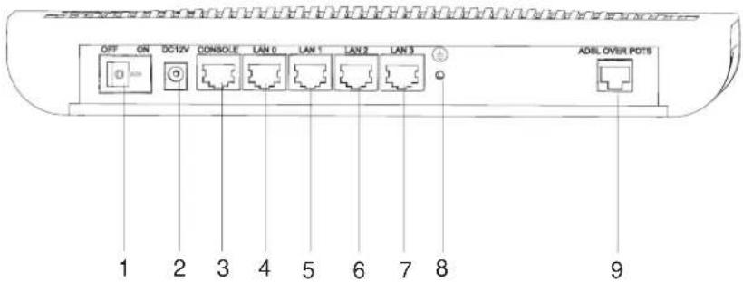
■1. Power switch
■2. Power input socket
■3. Console port (CON)
■4. Ethernet port 0 (LAN0)
■5. Ethernet port 1 (LAN1)
■6. Ethernet port 2 (LAN2)
■7. Ethernet port 3 (LAN3)
■8. Grouding screw
■9. ADSL port (ADSL ober POTS)
System specifications
Table 1 System specifications of Router 3030
| Item | 3030 Description | |
| Port 1 console port 1 ADSL over POTS (Annex A) | ||
| Four 10/100M Ethernet port (LAN) Processor MPC859 50Mhz | ||
| SDRAM 64MB Flash Memory | ||
| 8MB Maximum | power consumption | 12W |
| Power supply (external) Input rated voltage: 100-240V a.c., | 50/60Hz | |
| Maximum tollerance 90-264V a.c., 50/60Hz | Current: 0.5A~1A | Output |
| Voltage: 12V d.c. | Current:‘4A | Dimensions (W x H x D) |
| 300mm (11.81in) X 180mm (7.1in) X 45mm (1.77in) (Maximum dimensions, which are the highest arc points of the plastic panel.) | Weight 1kg | |
| Operating temperature | 0 to 40* C | Operating humidity |
| 10 to 90% (noncondensing) | ||
LEDs
There are eight LEDs on the cover. The following table explains their meaning.
Table 2 LEDs of Router 3030
| LED | Description |
| LAN0/LAN1/LAN2/LAN3 | OFF means that link is not set up. |
| ON means that link has been set up. | Blinking means that data is being sent from or received at the interface. |
| ADSL ACT | OFF means that no data is being sent from or received at the interface. |
| Blinking means that data is being sent from or received at the interface. | ADSL LNK |
| OFF means ADSL is inactive. | ON means ADSL is active. |
| Blinking means the interface is being trained. | SYS |
| Blinking means that the system is properly working. | Always ON or OFF means that the system is incorrectly working. |
| PWR | OFF means that power is not being supplied. |
| ON means that power is being supplied. |
Port attributes
The Router 3030 provides one console port, four 10/100M Ethernet ports and one ADSL over POTS port. The following table describes the attributes of ADSL over POTS port.
- ADSL over POTS port
Table 3 Attributes of ADSL over POTS port
| Attribute Description | |
| Connector RJ11 | |
| Rate ADSL full-rate mode (i.e. ITU-T 992.1 | G.DMT/ANSI T1.413) |
| 8Mbps in downstream and 800 kbps in upstream | ADSL Lite mode ((ITU-T 992.2 G.Lite): |
| In downstream, 64 kbps~1.5Mbps in steps of 32 kbps; in upstream, | 64 kbps~512 kbps in steps of 32 kbps |
| Interface standard ITU-T 992.1 G.DMT (Annex A) | |
| ITU-T 992.2 G.Lite ITU-T 994.1 handshaking | |
| ANSI T1.413 Issue 2 Services | |
| ADSL access over twisted pairs | |
Router 3031 and 3035
The following illustrations depict the components of the Router 3031/3035.
Figure 3 Router 3031/3035 Front Panel
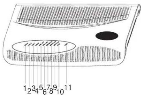
■1. ETH LED (LAN3)
■2. ETH LED (LAN2)
■3. ETH LED (LAN1)
■4. ETH LED (LAN0)
■5. ADSL active LED (DSL ACT)
■6. ADSL LINK LED (DSL LINK)
■7. ISDN B2 active LED (ISDN B2 ACT)
■8. ISDN B1 active LED (ISDN B1 ACT)
■9. ISDN link LED (ISDN LNK)
■10. System LED (SYS)
■11. Power LED (PWR)
Figure 4 Router 3031 Rear Panel

■1. Power switch
■2. power input socket
■3. Console port (CON)
■4. Ethernet port 0 (LAN0)
■5. Ethernet port 1 (LAN1
■6. Ethernet port 2 (LAN2
■7. Ethernet port 3 (LAN3)
■8. Grounding screw
■9. ISDN BRI port (3035 runs ADSL over ISDN)
■10. ADSL over POTS port
System specifications
Table 4 System specifications of Router 3031
| Item | 3031 Description | |
| Port 1 console port | 1 ADSL over POTS (3035 runs ADSL over ISDN)1 ISDN BRI S/T portFour 10/100M Ethernet ports | |
| Processor MPC859 50Mhz | ||
| SDRAM 64MB | ||
| Flash memory 8MB | ||
| Maximum power consumption | 12W | |
| Power Supply (external) | Input | rated voltage: 100-240V a.c., 50/60HzMaximum tolerance: 90-264V a.c., 50/60HzCurrent: 0.5A~1A |
| Output Voltage: 12V d.c. | ||
| Current: 4A | ||
| Dimensions (WxHxD) 300mm (11.81in) X 180mm (7.1in) X 45mm(1.77in) (Maximum dimensions, which are the highest arc points of the plastic panel.) | ||
| Weight 1kg | ||
| Operating temperature 0 to 40°C | ||
| Operating humidity | 10 to 90% (noncondensing) | |
LEDs
There are eleven LEDs on 3031 cover. The following table explains their meaning.
Table 5 LEDs of Router 3031
| LED | Description |
| LAN0/LAN1/LAN2/LAN3 | OFF means that link is not set up. |
| ON means that link has been set up. | Blinking means that data is being sent from or received at the interface. |
| ADSL ACT | OFF means that no data is being sent from or received at the interface. |
| Blinking means that data is being sent from or received at the interface. | ADSL LNK |
| OFF means ADSL is inactive. | ON means ADSL is active. |
| Blinking means the interface is being trained. | ISDN B1 ACT/ ISDN B2 ACT |
| OFF means B1 or B2 is inactive. | Blinking means B1 or B2 is active. |
| ISDN LNK | OFF means ISDN is inactive. |
| ON means ISDN is active. | SYS |
| Blinking means that the system is properly working. | Always ON or OFF means that the system is incorrectly working |
| PWR | OFF means that power is not being supplied. |
Table 5 LEDs of Router 3031
| LED Description |
| ON means that power is being supplied. |
Port attributes
The Router 3031 provides one console port, four 10/100M Ethernet port, one ISDN S/T port and one ADSL over POTS port.

These ports are configured and managed as a single logical entity.
Router 3032 The following illustrations depict the components of the Router 3032.
Figure 5 Router 3032 Front Panel

■1. ETH LED (LAN3)
■2. ETH LED (LAN2)
■3. ETH LED (LAN1)
4. ETH LED (LAN0)
■5. ADSL active LED (DSL ACT)
■6. ADSL LINK LED (DSL LINK)
■7. System LED (SYS)
■8. Power LED (PWR)
Figure 6 Router 3032 Rear Panel

■1. Power switch
■2. Power input socket
■3. Console port (CON)
■4. Ethernet port 0 (LAN0)
■5. Ethernet port 1 (LAN1)
■6. Ethernet port 2 (LAN2)
■7. Ethernet port 3 (LAN3)
■8. Grounding screw
■9. ADSL port (ADSL over ISDN)
System specifications
Table 6 System specifications of Router 3032
| Item | 3032 description | |
| Port 1 console port | ||
| 1 ADSI over ISDN (ADSL Annex B) | ||
| Four 10/00M Ethernet ports | ||
| Processor MPC859 50 Mhz | ||
| SDRAM 64MB | ||
| Flash Memory 8MB | ||
| Maximum power consumption 12W | ||
| Power supply (external) | input | rated voltage: 100-240V a.c., 50/60Hz |
| Maximum tolerance: 90-264V a.c., 50/60Hz | ||
| Current:0.5A~1A | ||
| Output Voltage: 12V d.c. | ||
| Dimensions (WxHxD) 300mm (11.81in) X 1800mm (7.1in) X 45mm(1.77in) (Maximum dimensions, which are the highest arc points of the plastic panel.) | ||
| Weight 1kg | ||
| Operating temperature | 0 to 40* C | |
| operating humidity | 10 to 90% (noncondensing) | |
LEDs
There are eight LEDs on 3032 cover. The following table explains their meaning.
Table 7 LEDs of Router 3032
| LED | Description |
| LAN0/LAN1/LAN2/LAN3 | OFF means that link is not set up. |
| ON means that link has been set up. | Blinking means that data is being sent from or received at the interface. |
| ADSL ACT | OFF means that no data is being sent from or received at the interface. |
| Blinking means that data is being sent from or received at the interface. | ADSL LNK |
| OFF means ADSL is inactive. | ON means ADSL is active. |
| Blinking means the interface is being trained. | SYS |
| Blinking means that the system is properly working. | Always ON or OFF means that the system is incorrectly working |
| PWR | OFF means that power is not being supplied. |
| ON means that power is being supplied. |
Port attributes
The Router 3032 provides one console port, four10/100M Ethernet port and one ADSL over ISDN port. The following table describes the attributes of ADSL over ISDN port.

These ports are configured and managed as a single logical entity.
- ADSL over ISDN port
Table 8 Attributes of ADSL over ISDN port
| Attribute Description |
| Connector RJ11 |
| Rate ADSL full-rate mode (i.e. ITU-T 992.1 G.DMT/ANSI T1.413) |
| 8Mbps in downstream and 800 kbps in Interface standard upstream |
| ITU-T 992.1 G.DMT ITU-T 994.1 handshaking |
| ANSI T1.413 Issue 2 Services |
| ADSL access over ISDN line |
Router 3033
The following illustrations depict the components of the Router 3033.
Figure 7 Router 3033 Front Panel

■1. ETH LED (LAN3)
■2. ETH LED (LAN2)
■3. ETH LED (LAN1)
■4. ETH LED (LAN0)
■5. G.SHDSL active LED (DSL ACT)
■6. G.SHDSL link LED (DSL LNK)
-7. System LED (SYS)
■8. Power LED (PWR)
Figure 8 Rear panel of Router 3033

-1. Power switch
■2. Power input socket
■3. Console port (CON)
■4. Ethernet port 0 (LAN0)
■5. Ethernet port 1 (LAN1)
■6. Ethernet port 2 (LAN2)
■7. Ethernet port 3 (LAN3)
■8. Grounding screw
■9. G.SHDSL port
System specifications
Table 9 System specifications of Router 3033
| Item | 3033 description |
| Port 1 console port | |
| 1 G.SHDSL port (Standard) | |
| Four 10/100M Ethernet ports | |
| Processor MPC859 50 Mhz | |
| SDRAM 64MB | |
| Flash memory 8MB | |
| Maximum power 12W | |
| Power supply consumption Input Rated voltage: 100-240V a.c., 50/60Hz | |
| Maximum tolerance: 90-264V a.c., 50/60Hz | |
| Current: 0.5A~1A | |
| Output Voltage: 12V d.c | |
| Current: 4A | |
| Dimensions (WxHxD) 300mm (11.81in) X 180mm (7.1in) X 45mm | |
| (1.77in) (Maximum dimensions, which are the highest arc points of the plastic panel.) | |
| Weight | 1kg |
| operating temperature | 0 to 40°C |
| Operating humidity | 10 to 90% (noncondensing) |
LEDs
There are eight LEDs on 3033 cover. The following table explains their meaning.
Table 10 LEDs of Router 3033
| LED | Description |
| LAN0/LAN1/LAN2/LAN3 | OFF means that link is not set up. |
| ON means that link has been set up. | Blinking means that data is being sent from or received at the interface. |
| ADSL ACT | OFF means that no data is being sent from or received at the interface. |
| Blinking means that data is being sent from or received at the interface. | ADSL LNK |
| OFF means G.SHDSL is inactive. | ON means G.SHDSL is active. |
| Blinking means the interface is being trained. | SYS |
| Blinking means that the system is properly working. | Always ON or OFF means that the system is incorrectly working |
| PWR | OFF means that power is not being supplied. |
| ON means that power is being supplied. |
Port attributes
3033 Router provides console port, 10/100M Ethernet port, ISDN S/T port and G.SHDSL port. The following table describes the attributes of G.SHDSL port.

These ports are configured and managed as a single logical entity.
G.SHDSL port
Table 11 Attributes of G.SHDSL port
| Attribute Description | |
| Connector RJ11 | |
| Rate In single-pair mode, it transceives packets at symmetric rate | |
| 192 kbps~2320 kbps, in steps of 8 kbps. | Interface standard |
| ITU-T G991.2 ITU-T G994.1 handshaking | |
| Services G.SHDSL access over single pair twisted pairs | |
Router 3034 The following illustrations depict the components of the Router 3034.
Figure 9 Router 3034 Front Panel

■1. ETH LED (LAN3)
■2. ETH LED (LAN2)
■3. ETH LED (LAN1)
■4. ETH LED (LAN0)
■5. G.SHDSL active LED (DSL ACT)
■6. G.SDHDSL link LED (DSL LNK)
■7. ISDN B2 active LED (ISDN B2 ACT)
■8. ISDN B1 active LED (ISDN B1 ACT)
■9. ISDN B2 link LED (ISDN LNK)
■10. System LED (SYS)
■11. Power LED (PWR)
Figure 10 Router 3034 Rear Panel

■1. Power switch
■2. Power input socket
■3. Console port (CON)
■4. Ethernet port 0 (LAN0)
■5. Ethernet port 1 (LAN1)
■6. Ethernet port 2 (LAN2)
■7. Ethernet port 3 (LAN3)
■8. Grounding screw
■9. ISDN BRI port
■10. .SHDSL port
System specifications
Table 12 System specifications of Router 3034
| Item | 3034 description | |
| Port 1 console port | ||
| 1 G.SHDSL port | ||
| 1 ISDN BRI S/T port | ||
| Four 10/100M Ethernet ports | ||
| Processor MPC859 50Mhz | ||
| SDRAM 64MB | ||
| Flash memory 8MB | ||
| Maximum power consumption | 12W | |
| Power supply (external) | Input | Rated voltage:100-240V a.c., 50/60Hz |
| Maximum tolerance: 90-264V a.c., 50/60Hz | ||
| Current: 0.5A~1A | ||
| Output Voltage: 12V d.c. | ||
| Current: 4A | ||
| Dimensions (WxHxD) 300mm (11.81in) X 180mm (7.1in) X 45mm | ||
| (1.77in) (Maximum dimensions, which are the highest arc points of the plastic panel.) | ||
| Weight 1kg | ||
| Operating temperature 0 to 40°C | ||
| Operating humidity 10-90% (noncondensing) | ||
LEDs
There are eleven LEDs on the 3034 cover. The following table explains their meaning.
Table 13 LEDs of Router 3034
| LED Description | |
| LAN0/LAN1/LAN2/LAN3 OFF means that link is not set up. | |
| ON means that link has been set up. | Blinking means that data is being sent from or received at the interface. |
| SHDSL ACT | OFF means that no data is being sent from or received at the interface. |
| Blinking means that data is being sent from or received at the interface. | SHDSL LNK |
| OFF means ADSL is inactive. | ON means ADSL is active. |
| Blinking means the interface is being trained. | ISDN B1 ACT/ ISDN B2 ACT |
| OFF means B1 or B2 is inactive. | Blinking means B1 or B2 is active. |
| ISDN LNK | OFF means ISDN is inactive. |
| ON means ISDN is active. | SYS |
| Blinking means that the system is properly working. | Always ON or OFF means that the system is incorrectly working |
| PWR | OFF means that power is not being supplied. |
Table 13 LEDs of Router 3034
| LED Description |
| ON means that power is being supplied. |
Port attributes
The 3Com Router 3034 provides one console port, four 10/100M Ethernet port, ISDN S/T port and G.SHDSL port.

These ports are configured and managed as a single logical entity.
3
INSTALLING THE ROUTER
General Site Requirements To ensure the proper working of the routers, and to prolong their service life, the installation site should meet the requirements described in the following subsections.
Requirements on Environment
3000 DSL Family must be used indoors. To ensure the normal operation and prolong their service life, the following requirements for installation site must be met.
Requirements on Temperature/Humidity
Certain requirements on temperature and humidity in the equipment room shall be met. If the relative humidity is too high, the insulation materials in it will deteriorate easily or even lead to electric leakage. Sometimes this will result in a change of the mechanical performance of the materials, and rusting of the metal components. If the relative humidity is too low, the fastening screw will loosen due to shrinkage of the isolation spacer. In an environment with a dry climate static electricity may be produced, putting the CMOS of the router to risk. High temperature is of the greatest risks, for it will significantly degrade the router's reliability, speed up the aging process of the insulating materials, and shorten the service life of the router. Below are the requirements on the temperature and humidity for 3000 DSL Family:
Table 1 Humidity requirements in the equipment room
| Temperature Relative humidity |
| 0°C to 40°C 10% to 90% |
Cleanliness Requirements
Dust undermines the normal operation of 3000 DSL Family. Dust on the equipment can cause electrostatic adsorption, which degrades the contact performance of the metal connectors or connection points. This happens more frequently when the indoor humidity is low, which will not only shorten the router's service life, but also cause communication failure.
Below is the recommended specification on dust content and particle diameter in the equipment room:
Table 2 Specifications on dust content in equipment room
| Maxim diameter (l)m | Max. intensity (particles/m3) |
| 0.5 1.4 x 10 | 7 |
| 1 7 x 10 | 5 |
| 3 2.4 x 10 | 5 |
| 5 1.3 x 10 | 5 |
The routers also have rigorous demands on the content of salts, acids and sulfides in the air. These harmful gases will speed up the aging processes of certain parts and cause a more rapid rusting of the metal parts. The equipment room should be protected from the invasion of harmful gases such as SO2, H2S, NO2, NH3, and Cl2, the value limits of which are shown below:
Table 3 Value limits for harmful gas content in equipment room
| Gas Average (mg/m) | ^3) Max. (mg/m ^3) | |
| SO_2 | 0.2 1.5 | |
| H_2S 0 0.03 | ||
| NO_2 | 0.04 0.15 | |
| NH_3 | 0.05 0.15 | |
| Cl_2 | 0.01 0.3 | |
ESD Preventative Requirements
Although many anti-static considerations have been given to 3000 DSL Family, damage to the router's circuit or even the whole equipment is still possible when the static electricity exceeds the tolerance threshold.
In the communication network to which the routers are connected, static induction mainly comes from:
- External electric fields such as outdoor high voltage power lines or thunder.
- Internal environment like flooring materials or the whole equipment structure.
The following should be considered to safeguard the equipment against the ESD:
- Make sure that the equipment and the floor are well grounded.
■Make sure that dust-proof measures are taken.
- Maintain an appropriate humidity and temperature.
- Wear an ESD-preventive wrist strap and uniform when contacting the circuit board.
- Place the uninstalled circuit board on the antistatic workbench, with its face upward, or put it into the static shielding bag.
- When observing or removing the uninstalled circuit board, please touch the edge of the circuit board, and avoid contacting the devices on it.
Electromagnetic Environment Requirements
The interference sources, no matter where they come from, affect the routers with capacitance coupling, inductance coupling, radiation of electromagnetic wave, common impedance (including the grounding system) or conducting line (power line, signal line and transmission line etc.). The following should be considered:
- Take effective measures to prevent the power system from being interfered with by the power grid system.
- Keep the router far away from the radio launcher, radar launcher, and high-frequency devices working in high currents.
- Use electromagnetic shielding when necessary.
Lightning Protection Requirements
Many measures have been taken to protect 3000 DSL Family from lightning. However, if the lightning intensity exceeds a certain range, damage to the router is still possible. To better protect the router from lightning, the following should be considered:
- Ensure the PGND wire of the chassis is well grounded.
- Ensure the ground point of the socket of AC power supply is well grounded.
- To enhance the lightning protection capability of the power supply, a lightning arrester could be installed at the input end of the power supply.
- As for the signal line outdoors to which the interface modules of 3000 DSL Family routers are connected, such as ISDN line, telephone line, T1 line, etc, a special lightning arrester should be installed at the input end of the signal line to enhance the lightning protection capability.
Table Mount Requirements
- There is spacing reserved at the air inlet and outlet in the router so as to facilitate the radiation of the router cabinet.
- The workbenches have good radiation systems.
- The workbenches are firm enough to support the weight of the router and other installation accessories.
■The workbench are well grounded.
Precautions
Routers play a key role in data communications network. Please pay attention to the following:

It indicates that this operation is incorrect and may seriously damage the router or endanger the operator. Please follow the correct operation procedures for sake of safety.

It indicates that during the installation and usage of the router, the operation needs attention. This operation is incorrect and perhaps will affect the normal operation of the router.
Please follow these safety recommendations during the installation and use of the router:
- Keep the router away from any wet place or a heat source.
- Make sure that the router is normally grounded.
- Please wear an ESD-preventive wrist strap before installation; make sure one end securely contacts your skin, and the other end is well grounded.
- Do not hot swap any cable.
- Correctly connect the interface cable for the router. Do not connect the telephone cable (including the ISDN cable) to the AUX port or the console port.
■Always use Uninterrupted Power Supply (UPS).
Installation Tools, Meter and Equipment
Tools
Phillips screwdriver
- Flat-head screwdriver
-ESD-preventive wrist strap
Cables
■Ground wire, power supply and power cord
- Console cable
.Ethernet cable
- Synchronous/Asynchronous serial cable (optional)
Equipment and meter
.HUB or LANSwitch

The installation tools, equipment and meter are not delivered with 3Com 3000 DSL Family Routers.

CONFIGURING THE ROUTER
Setting up Configuration Environment
Connecting the router to a console terminal
To set up a local configuration environment, simply connect the RJ45 connector of the console cable to the console port on the router, and DB25 or DB9 connector to the serial interface of a PC, as shown below.
Figure 1 Local configuration through CON port

Setting the parameters of console terminal
1 Start the console terminal and set up a new connection
If the configuration is performed through a PC, the terminal emulation program (such as Terminal of Windows3.1 and HyperTerminal of Windows95/98/NT) should be run on the PC for setting up a new connection. As shown below, enter a name for the new connection and press

Figure 4-2New connection
2 Set the terminal parameters
Parameters of the HyperTerminal of Windows 98 are set as follows:
a Select a connection port
Select the serial interface to be connected in the Connect Using box. The selected serial interface should be the same port as that the console cable connects.
b Set the serial interface parameters. As shown below, in the properties dialog box of the serial interface, set the baud rate to 9600, data bit to 8, parity to none, stop bits to 1 and flow control to none, and click the
Figure 2 Setting serial interface parameters

c Set HyperTerminal properties. Select [Properties/Settings] in the HyperTerminal for entering the properties setting interface. Select [VT1100] or [Auto detect] for emulation, and press
Figure 3 Setting terminal type

Powering on the Router Checking before power-on
Check before powering on the router to ensure that:
- Power cord and ground wire are correctly connected.
■Proper power supply voltage is used. - The console cable is correctly connected, and configuration PC or console terminal has been started and the parameters involved have been set.

Locate the emergency power-off switch in the room where you are working before powering on the router. Then, if an electrical accident occurs, you can quickly shut the power OFF.
Powering on the router
Turn on the power switch of the router.
Checking/Operating after power-on
After the router is powered on, perform a check to ensure that:
- LEDs on the cover are displaying correctly.
- Refer to the descriptions of LED states when the router is running.
- The console terminal display is correct.
- In the console terminal, you can see the startup interface after the router is powered on.
After the Power-On Self-Test (POST), you are prompted to press
Startup Process
The following describes the startup process for all Router 3000 DSL Family products.
Router starts booting... (V2.00)
Starting at 0x1500000...
**************************
*
* 3Com Series Routers Boot ROM, V9.00 *
*
**************************
Copyright(C) 1997-2003 by 3Com Corporation CO.
Compiled at 17:11:06, Aug 19 2003.
Testing memory...OK!
64M bytes SDRAM
8192k bytes flash memory
Hardware Version is MTR 2.0
CPLD Version is CPLD 1.0
Press Ctrl-B to enter Boot Menu
System is self-decompressing....OK!
System is starting...
Starting at 0x10000...
If no registration authentication is set, press
<Router>
It means the system enters the user view and is ready for your configuration.
Configuration Fundamentals of the Router
In general, the configuration steps are as follows:
1 Before configuring a router, you should make the networking requirements clear and specific, including networking purpose, the role of the router in the network, division of subnets, WAN type and transmission medium, network security policy and reliability.
2 Draw a clear and integrated networking diagram.
3 Configure the IP addresses or IPX network numbers of all the interfaces on the router on the basis of subnet division.
4 Configure the routes. If it is necessary to start the dynamic routing protocol, you should also configure the related operating parameters for the protocol.
5 If security is required, perform the security configuration for the router.
6 If reliability is required, perform the reliability configuration for the router.

Although this devices has 4 physical ports it has only a single logical ethernet interface, Ethernet1/0.
Command Line Interface
The command line interface of 3Com Router 3000 DSL has a number of configuration commands, which can be used to configure and manage the routers. The command line interface has the following characteristics:
- Performing local configuration through CON port.
- Performing local or remote configuration through the Telnet command, which can be used to directly log on and manage other routers.
- Configuring the hierarchical user protection (includes guest, operator, administrator). Only administrator users are authorized to configure and manage the routers, so that unauthorized users would not be able to invade the router illegally.
- Users can enter <?> at any time to get online help.
- Providing network diagnostic tools, such as Tracert and Ping, to quickly diagnose the accessibility of the network.
- Providing all kinds of detailed debugging information to diagnose network faults.
- The command line interpreter adopts fuzzy search for the keywords of the command. Thus, you only need to enter the conflict-free keyword for the interpretation of a command. For example, for the interpretation of a display command, you can just input "dis".
The command line interface of 3Com Router 3000 DSL provides plenty of configuration commands. Hierarchical user protection is adopted to prevent unauthorized users from intruding.
In the system view, to facilitate the router management, all the commands are grouped. Each group associates with a view. Users can use these commands to switch between different configuration views. Normally, only certain commands can be executed under a certain configuration mode, but some commands in common use (such as ping, display current-configuration, and interface) can be executed in all views.
SNMP Management
For help managing routers on your network, you can use 3Com Network Director software to discover, map, and display network links and IP devices.
To allow Network Director to monitor your routers, you must first configure SNMP V1 and SNMP Trap support with the following commands:
[3Com] snmp-agent sys-info version v1
[3Com] snmp-agent community read
[3Com] snmp-agent community write
[3Com] snmp-agent trap enable
In this example,
To learn more about Network Supervisor, on the 3Com Corporation World Wide Web site, enter this URL into your Internet browser:
http://www.3com.com/3nd
5
SOFTWARE MAINTENANCE
Software The files managed by the router are of 3 types:
-Boot ROM file
-Application file (main software)
-Configuration file
The router software maintenance mainly refers to the maintenance of those three types of files, including upgrade and download of Boot ROM and application files, as well as upload and download of configuration file.
Boot Menu This section introduces the Boot menu, which is used during the software maintenance of a router.
Set up configuration environment in accordance with Figure 4.1 Local configuration through CON port, and then start the router. When the configuration terminal prompts the information “Press Ctrl-B to enter Boot Menu”, press
Please input Boot ROM password:

Press
To enter the Boot menu after the router starts the program decompression process, reboot the router.
Enter the correct password, then press
Boot menu on 3000 DSL Family
Boot Menu:
1: Download application program with XMODEM
2: Download application program with NET
3: Clear configuration
4: Clear application password
5: Start up and ignore configuration
6: Enter debugging environment
7: Boot Ram Operation Menu
8: Do not check the version of the software
9: Exit and reboot
Enter your choice(1-9):
In this menu, only options 2, 4 and 6 are different, so only they are detailed here. For other options, refer to Boot menu on the 3000 DSL.
1 Download application program with Ethernet.
This option leads you into NET port download menu, which includes these options:
Net Port Download Menu:
1: Change Net Parameter
2: Download From Net
3: Exit to Main Menu
Enter your choice(1-3):1
They are described as follows:
-Change NET parameter
The following information is prompted for this option:
Change Boot Parameter:
    '.' = clear field; '-' = go to previous field; ^D = quit
    boot device : fei0
    processor number : 0
    host name : 8040
    file name : M8240ram.arj
    inet on ethernet (e) : 169.254.10.10
    inet on backplane (b):
    host inet (h) : 169.254.10.11
    gateway inet (g) :
    user (u) : 8040
    ftp password (pw) (blank = use rsh):
    flags (f) : 0x0
    target name (tn) :
    startup script (s) :
    other (o) :

The information after the colon is just for prompt, so you can enter the parameters you select directly behind it.
Both TFTP and FTP are available for the 3000 DSL. See Upgrading Application Program with EthernetUpgrading Application Program with Ethernet for details.
.Download from NET.
Select this option to begin downloading after parameters are set properly.
.Exit to Main Menu.
2 Clear application password
This option clears super user password. This option functions only one time and password authentication for super users is restored after the router is rebooted.
3 Enter debugging environment in case of faults.
Boot menu provides two methods for upgrading the program and the Boot ROM sub-menu operations, which are introduced in the following subsections.

It is recommended to upgrade the software under the guidance of the technical support personnel. In addition, when upgrading the router, note to match the version of the Boot ROM software with that of the main software.
Upgrading Application Program and Boot ROM through XModem Protocol
When upgrading the software through the XModem protocol, you can simply use the console port rather than building up another configuration environment.
Upgrading application program
1 Enter the Boot menu, press <1> to select the XModem protocol for downloading the application program. The following download speeds are available for the router:
Downloading application program from serial...
Please choose your download speed:
1: 9600 bps
2: 19200 bps
3: 38400 bps
4: 57600 bps
5: 115200 bps
6: Exit and reboot
Enter your choice(1-6):
2 Select an appropriate download speed. For example, enter <5> to select the download speed 115200 bps and the router will prompt:
Download speed is 115200 bps. Change the terminal's speed to 115200 bps, and select XModem protocol. Press ENTER key when ready.
3 According to the above information, change the baud rate set at the console terminal for keeping it in consistency with the selected software download baud rate. After that, disconnect the terminal (that is [Dial-in/Disconnect]), reconnect it (that is [Dial-in/Dialing]) and then press
Downloading... CCCCC

After the baud rate at the console terminal is set, the new setting can become valid only if the terminal emulation program is disconnected and reconnected at least once.
4 Select [Transmit/send file] in the terminal window and the following dialog box will pop up:
Figure 1 Send File dialog box

5 Click
Figure 2 Sending file interface

6 After completing download, the system begins writing to Flash (Flash memory), then the following information will be displayed in the terminal interface, indicating that the download has been completed:
Download completed. Writing to flash memory... Please wait, it needs a long time. Please wait...
Writing FLASH Success.
Please use 9600 bps.Press
Restore the baud rate of the configuration terminal to 9600bps as per the prompt (disconnection and re-dialing are also required here), and then the system start up normally.
Upgrading the entire Boot ROM program
1 Enter Boot menu (see Boot MenuBoot Menu), select <7> for the 3000 DSL to turn to Boot ROM operation menu.
2 Select <1> in the Boot ROM operation sub-menu to download the Boot ROM program with XModem. The Router provides you with several speeds. The subsequent operation steps are the same as those described in "I".

If the all Boot ROM program fails during upgrade, it cannot be restored on site. Therefore, only when necessary can you upgrade the whole Boot ROM, besides, you must upgrade under the guide of technical support personnel.
Upgrading the extended segment of Boot ROM program
1 Enter Boot menu (see Boot MenuBoot Menu), select <7> for the 3000 DSL to turn to Boot ROM operation menu.
2 Select <2> in the operation sub-menu to upgrade the extended segment of Boot ROM program with XModem. The Router provides you with several speeds. The subsequent operation steps are the same as those described in "I.
Backing up and Restoring the Extended Segment of Boot ROM Program
Backup the extended segment of Boot ROM Program in FLASH
1 Enter Boot menu (see Boot MenuBoot Menu), select <7> to turn to Boot ROM operation menu.
2 Select <4> in the operation sub-menu to copy the current extended segment of Boot ROM program into the FLASH, and then the following information will be displayed in the terminal interface if the restoring operation is successful.
Writing to FLASH.Please wait...###
Backuping Boot ROM program to FLASH succeeded!
3 When the sub-menu appears again, select <5> to exit the Boot menu and proceed to execute the router's main software.
Restore the extended segment of Boot ROM program from FLASH
In case that faults occur to the extended segment of the Boot ROM program that is in use, or you upgrade the extended segment wrongly, you can restore the extended segment saved in FLASH into the Boot ROM by doing the following:
1 Enter Boot menu (see Boot MenuBoot Menu), select <7> to turn to Boot ROM operation menu.
2 Select <3> in the operation sub-menu to restore Boot ROM from FLASH, and then the following information will be displayed if the restoring operation is successful.
Writing to Boot ROM.Please wait...### Restoring Boot ROM program successful!
3 When the sub-menu appears again, select <5> to exit the Boot menu and proceed to execute the router's main software.
Upgrading Application Program with Ethernet
It refers to downloading application program through Ethernet port. The router serves as client, so it needs to be connected to TFTP Server or FTP Server through its fixed Ethernet port. The following are the details.

TFTP Server or FTP Server program is not included in 3Com routers, so you have to buy and install it.
For 3000 DSL Family
Both TFTP loading and FTP loading are available in 3000 DSL routers.
1 Start TFTP or FTP Server
Start TFTP server or FTP server at the PC connecting the Ethernet port of the router and configure path for the files to be loaded. For FTP Server, you should also set username and password.
2 Enter NET download menu
Select <2> in BOOT menu to turn to NET download menu.
3 Configure parameters
Select <1> in NET download menu to turn to parameter configuration interface.
- Configure these parameters for TFTP mode file name: File name to be loaded inet on ethernet (e): IP address for the Ethernet port for loading host inet (h): IP address for TFTP Server flags (f): The flag must be 0x80 for TFTP mode
- Configure these parameters for FTP mode file name: File name to be loaded inet on ethernet (e): IP address for the Ethernet port for loading host inet (h): IP address for FTP Server user (u): User name, which must be consistent with that for FTP Server ftp password (pw) (blank = use rsh): Password, which must be consistent with that for FTP Server flags (f): The flag must be 0x0 for FTP mode.
These parameters will be saved automatically when your configuration is completed.
4 Router restarts after successful upgrading
Press
boot device : fei
unit number : 0
processor number : 0
host name : 8040
file name : Q8040.BIN
inet on ethernet (e) : 10.110.27.235
host inet (h) : 10.110.27.231
user (u) : 8040
ftp password (pw) : 8040
flags (f) : 0x80
Attached TCP/IP interface to fei0.
Subnet Mask: 0xfffff800
Attaching network interface lo0... done.
Loading...
NET download completed...
read len = [04378489]
Please wait, it needs a long time
######
######
######
Writing Vrpsoftware File Succeeds!
Press
5 Press
Up/Downloading Application, Boot ROM program and Configuration File Using FTP
3com Router 3000 DSL provides FTP Server function for updating application file, Boot ROM program, or configuration file. Any FTP Client (including local and remote users) connected to a router can perform the operation. Configuration file, Boot ROM program, or application files can be uploaded/downloaded if the user passes authentication. Follow these steps to upload/download the application/Boot ROM program/configuration file through FTP:

Upload: Transmit files from the PC running as FTP client to the router connected to the PC via the Ethernet interface, that is, perform the put operation.
Download: Transmit files from the router to the PC running as FTP client, which is connected to the Ethernet interface of the router, that is to implement the get operation.
Building up upload/download environment
Build up FTP local upload/download environment
Figure 3 Building up FTP local upload/download environment

flowchart
graph LR
    A["10.110.10.13"] --> B["LAN"]
    C["Ethernet port 10.110.10.10"] --> B
    B --> D["Computer"]
PC (FTP Client)
1 Connect the Ethernet interface on the router to the PC.
2 Assign an IP address for the Ethernet interface on the router. It is assumed to be 10.110.10.10.
3 Assign an IP address for the Ethernet interface on the PC. It is assumed to be 10.110.10.13.
4 Copy the application files, Boot ROM program or configuration files to a directory, which is assumed to be "C:\version".

The IP addresses of the network interface on the PC and the router's Ethernet interface must be on the same segment.
Build up FTP remote upload/download environment
1 Connect the PC to any port of the router through a WAN. This approach does not require the IP addresses of the PC and the router to be on the same segment and is used for upgrading the router remotely.
2 Copy the application files, Boot ROM program or configuration files to a directory, which is assumed to be "C:\version".
Starting the FTP server
Perform the following configurations with the help of the maintenance personnel at the router side:
1 Set authentication mode

You can select an AAA configuration scheme depending on the actual situation.
2 Add user name and password
[Router] local-user router password simple 123 service-type ftp
"Router" represents the user name and "123" the password.
3 Start FTP server.
[Router] ftp-server enable
With these operations, the FTP server has been started on the router and the username has been set. In this case, all the FTP client programs can use the username and password to log onto the FTP server.
Uploading/Downloading Application file, Boot ROM program, or Configuration Files
1 Enter the directory containing the application file, Boot ROM program or configuration files in the DOS state. Execute the ftp command to set up an FTP connection with the router. For example:
C:\version\ftp 10.110.10.10
If the connection is set up, the following information will be displayed (taking Windows98 as an example):
Connected to 10.110.10.10 220 FTP server ready on Router at User(10.110.10.10: (none)):
2 Log in the FTP server with the username and password set on the router.
User(10.110.10.10:(none)): Router 331 Password required for ftp Password: 230 User ftp logged in ftp>
The appearance of the prompt "ftp>" means that you can begin the upload/download operation.
3 Upload/Download the application files, Boot ROM program or configuration files.

By default, the application file and configuration file on the router are respectively named "system" and "config.cfg", the file of the extended Boot ROM program segment is named "bootrom", and the entire Boot ROM file name defaults to bootromall.
- Upload the application program file or Boot ROM program or configuration file.
ftp>put
local file (Input the name of application/Boot ROM program/Configuration file to be uploaded.)
remote file (Input the name of application/Boot ROM program/Configuration file to be saved at the router side after uploading.)
After the uploading is completed, the prompt “ftp>” will be displayed again. Enter
-Download the application or Boot ROM program or configuration file.
ftp>get
local file (Input the name of application/Boot ROM program/Configuration file to be saved.)
remote file (Input the name of application/Boot ROM program/Configuration file at the router side)
4 After implementing uploading/downloading, exit the FTP client program.
ftp>quit
6
TROUBLESHOOTING
Troubleshooting Power System
Fault: POWER LED does not light.
Please Check:
■The power switch of the router has been turned on.
- The switch of the power supply has been turned on.
■The power cord of the router is properly connected.
■The power supply can work with the router.

Do not plug/unplug the power cord when the power is ON.
Troubleshooting Configuration System
After the Power-On Self-Test (POST) of the router, if the system operates normally, the start-up information should be displayed on the console terminal. If the configuration system has faults, the terminal may not display anything or may display only illegible characters.
Fault: "nothing being displayed on the terminal"
Symptom:
The console terminal does not display any information after POST of the router.
Solution
1 Check that:
■The power system is correctly working.
- The console cable is connected correctly.
2 If the problem is not located yet, proceed to check the console cable and the terminal (such as the HyperTerminal) parameter settings.
Fault: "displaying illegible characters on the terminal"
Symptoms
The console terminal displays illegible characters after the POST of the router.
Solution
Verify whether the terminal (e.g., the HyperTerminal) parameter are set as follows: Baud rate: 9600, Data bits: 8, Stop bit: 1, Parity: None, Flow control: None, and Terminal emulation: VT100 or Auto detect. If the parameters do not match the above values, make reconfiguration.

OBTAINING SUPPORT FOR YOUR PRODUCT
| Register Your Product to Gain Service Benefits | To take advantage of warranty and other service benefits, you must first register your product at http://eSupport.3com.com/. 3Com eSupport services are based on accounts that you create or have authorization to access. First time users must apply for a user name and password that provides access to a number of eSupport features including Product Registration, Repair Services, and Service Request. |
| Purchase Value-Added Services | To enhance response times or extend warranty benefits, contact 3Com or your authorized 3Com reseller. Value-added services can include 24x7 telephone technical support, software upgrades, onsite assistance or advance hardware replacement. Experienced engineers are available to manage your installation with minimal disruption to your network. Expert assessment and implementation services are offered to fill resource gaps and ensure the success of your networking projects. More information on 3Com Extended Warranty and Professional Services is available at http://www.3com.com/Contact your authorized 3Com reseller or 3Com for additional product and support information. |
| Troubleshoot Online | You will find support tools posted on the 3Com web site athttp://www.3com.com/▪ 3Com Knowledgebase helps you troubleshoot 3Com products. This query-based interactive tool is located at http://knowledgebase.3com.com and contains thousands of technical solutions written by 3Com support engineers.▪ Connection Assistant helps you install, configure and troubleshoot 3Com desktop and server NICs, wireless cards and Bluetooth devices. This diagnostic software is located at:http://www.3com.com/prodforms/software/connection_assistant/ca_thankyou.html |
| Access Software Downloads | Software Updates are the bug fix / maintenance releases for the version of software initially purchased with the product. In order to access these Software Updates you must first register your product on the 3Com web site athttp://eSupport.3com.com/.First time users will need to apply for a user name and password. A link to software downloads can be found athttp://eSupport.3com.com/, or under the Product Support heading athttp://www.3com.com/Software Upgrades are the software releases that follow the software version included with your original product. In order to access upgrades and related documentation you must first purchase a service contract from 3Com or your reseller. |
| Contact Us | 3Com offers telephone, e-mail and internet access to technical support and repair services. To access these services for your region, use the appropriate telephone number, URL or e-mail address from the list below. You will find a current directory of support telephone numbers posted on the 3Com web site athttp://csoweb4.3com.com/contactus/ |
| Telephone Technical Support and Repair | To obtain telephone support as part of your warranty and other service benefits, you must first register your product athttp://eSupport.3com.com/When you contact 3Com for assistance, please have the following information ready:Product model name, part number, and serial numberA list of system hardware and software, including revision levelDiagnostic error messagesDetails about recent configuration changes, if applicableTo send a product directly to 3Com for repair, you must first obtain a return authorization number (RMA). Products sent to 3Com, without authorization numbers clearly marked on the outside of the package, will be returned to the sender unopened, at the sender's expense. If your product is registered and under warranty, you can obtain an RMA number online athttp://eSupport.3com.com/. First time users will need to apply for a user name and password.Telephone numbers are correct at the time of publication. Find a current directory of support telephone numbers posted on the 3Com web site athttp://csoweb4.3com.com/contactus/ |
Country Telephone Number Country Telephone Number
| Asia, Pacific Rim Telephone Technical Support and Repair | |||
| Australia | 1 800 678 515 | Philippines | 1235 61 266 2602 or |
| Hong Kong | 800 933 486 | 1800 1 888 9469 | |
| India | +61 2 9424 5179 or000800 650 1111 | P.R. of China | 10800 61 00137 or021 6350 1590 or |
| Indonesia | 001 803 61009 | 00800 0638 3266 | |
| Japan | 00531 616 439 or03 5977 7991 | SingaporeS. Korea | 800 6161 463080 333 3308 |
| Malaysia | 1800 801 777 | Taiwan | 00801 611 261 |
| New Zealand | 0800 446 398 | Thailand | 001 800 611 2000 |
| Pakistan | +61 2 9937 5083 | ||
You can also obtain support in this region using the following e-mail: apr_technical_support@3com.com
Or request a repair authorization number (RMA) by fax using this number: +65 543 6348
Europe, Middle East, and Africa Telephone Technical Support and Repair
Country Telephone Number Country Telephone Number
| From anywhere in these regions, call: | +44 (0)1442 435529 | ||
| From the following countries, you may use the numbers shown: | |||
| Austria | 01 7956 7124 | Luxembourg | 342 0808128 |
| Belgium | 070 700 770 | Netherlands | 0900 777 7737 |
| Denmark | 7010 7289 | Norway | 815 33 047 |
| Finland | 01080 2783 | Poland | 00800 441 1357 |
| France | 0825 809 622 | Portugal | 707 200 123 |
| Germany | 01805 404 747 | South Africa | 0800 995 014 |
| Hungary | 06800 12813 | Spain | 9 021 60455 |
| Ireland | 01407 3387 | Sweden | 07711 14453 |
| Israel | 1800 945 3794 | Switzerland | 08488 50112 |
| Italy | 199 161346 | U.K. | 0870 241 3901 |
You can also obtain support in this region using the following URL: http://emea.3com.com/support/email.html
Latin America Telephone Technical Support and Repair
| Antigua | 1 800 988 2112 | Guatemala | AT&T +800 998 2112 |
| Argentina | 0 810 444 3COM | Haiti | 57 1 657 0888 |
| Aruba | 1 800 998 2112 | Honduras | AT&T +800 998 2112 |
| Bahamas | 1 800 998 2112 | Jamaica | 1 800 998 2112 |
| Barbados | 1 800 998 2112 | Martinique | 571 657 0888 |
| Belize | 52 5 201 0010 | Mexico | 01 800 849CARE |
| Bermuda | 1 800 998 2112 | Nicaragua | AT&T +800 998 2112 |
| Bonaire | 1 800 998 2112 | Panama | AT&T +800 998 2112 |
| Brazil | 0800 13 3COM | Paraguay | 54 11 4894 1888 |
| Cayman | 1 800 998 2112 | Peru | AT&T +800 998 2112 |
| Chile | AT&T +800 998 2112 | Puerto Rico | 1 800 998 2112 |
| Colombia | AT&T +800 998 2112 | Salvador | AT&T +800 998 2112 |
| Costa Rica | AT&T +800 998 2112 | Trinidad and Tobago | 1 800 998 2112 |
| Curacao | 1 800 998 2112 | Uruguay | AT&T +800 998 2112 |
| Ecuador | AT&T +800 998 2112 | Venezuela | AT&T +800 998 2112 |
| Dominican Republic | AT&T +800 998 2112 | Virgin Islands | 57 1 657 0888 |
You can also obtain support in this region using the following:
Spanish speakers, enter the URL:
http://lat.3com.com/lat/support/form.html
Portuguese speakers, enter the URL:
http://lat.3com.com/br/support/form.html
English speakers in Latin America should send e-mail to:
lat support anc@3com.com
US and Canada Telephone Technical Support and Repair
1 800 876 3266

- UNITED STATES GOVERNMENT LEGEND
- CONTENTS
- ABOUT THIS GUIDE
- INTRODUCING THE ROUTER 3000 DSL FAMILY
- INSTALLING THE ROUTER
- CONFIGURING THE ROUTER
- SOFTWARE MAINTENANCE
- TROUBLESHOOTING
- A OBTAINING SUPPORT FOR YOUR PRODUCT
- Conventions
- Related Documentation
- INTRODUCING THE ROUTER 3000 DSL FAMILY
- Router 3000 DSL Family
- System specifications
- LEDs
- Port attributes
- Router 3031 and 3035
- Router 3033
- 3
- INSTALLING THE ROUTER
- Requirements on Environment
- Requirements on Temperature/Humidity
- Cleanliness Requirements
- ESD Preventative Requirements
- Electromagnetic Environment Requirements
- Lightning Protection Requirements
- Table Mount Requirements
- Precautions
- Installation Tools, Meter and Equipment
- Tools
- Cables
- Equipment and meter
- CONFIGURING THE ROUTER
- Setting up Configuration Environment
- Set the terminal parameters
- Powering on the Router Checking before power-on
- Powering on the router
- Checking/Operating after power-on
- Startup Process
- Configuration Fundamentals of the Router
- Command Line Interface
- SNMP Management
- 5
- SOFTWARE MAINTENANCE
- Boot menu on 3000 DSL Family
- -Change NET parameter
- .Download from NET.
- .Exit to Main Menu.
- Upgrading Application Program and Boot ROM through XModem Protocol
- Upgrading application program
- Upgrading the entire Boot ROM program
- Upgrading the extended segment of Boot ROM program
- Backing up and Restoring the Extended Segment of Boot ROM Program
- Restore the extended segment of Boot ROM program from FLASH
- Upgrading Application Program with Ethernet
- For 3000 DSL Family
- Up/Downloading Application, Boot ROM program and Configuration File Using FTP
- Building up upload/download environment
- Starting the FTP server
- 6
- TROUBLESHOOTING
- Troubleshooting Power System
- Please Check:
- Troubleshooting Configuration System
- Symptom:
- Solution
- Symptoms
- OBTAINING SUPPORT FOR YOUR PRODUCT
Brand : 3COM
Model : Router 3033
Category : Router