
VT2755LED - Screen VIEWSONIC - Free user manual and instructions
Find the device manual for free VT2755LED VIEWSONIC in PDF.


| Product Type | 27-inch LED TV (LCD with LED backlight) |
| Model Number | VT2755LED (VS14569-1M) |
| Display | 27" TFT Active Matrix, 1920 x 1080 @ 60 Hz |
| Aspect Ratio | 16:9 |
| Dimensions (W x H x D) | 646.3 x 466.2 x 227.8 mm (25.44" x 18.35" x 8.97") |
| Weight (Net) | 5.95 kg (13.12 lb) |
| Power Supply | 100-240 VAC, 50/60 Hz (auto switch) |
| Power Consumption (On) | < 55 W (Max) |
| Power Consumption (Standby) | < 1 W @ 115 Vac |
| Input Signals | VGA, DVI, HDMI, YPbPr, S-Video, Composite, USB (JPEG/MP3), RF (NTSC/ATSC/Cable) |
| Audio Output | 2 x 5W speakers, Headphone jack, SPDIF Optical |
| VESA Mount | 100 x 100 mm, Screw M4 x L10 |
| RS232 Control | 9-pin D-sub for service/remote control |
| Energy Star | Yes (Home mode recommended) |
| Safety Certifications | UL/cUL, FCC-B, NOM, BETS-7, ENERGY STAR, NRCan, CEC |
| Cleaning Instructions | Unplug; use soft dry cloth; mild soap solution for stubborn stains; avoid solvents |
| Operating Temperature | 0°C to +40°C (32°F to 104°F) |
| Storage Temperature | -20°C to +60°C (-4°F to 140°F) |
| Warranty | 3 years parts (excluding light source) and 3 years labor |
Frequently Asked Questions - VT2755LED VIEWSONIC
User questions about VT2755LED VIEWSONIC
0 question about this device. Answer the ones you know or ask your own.
Ask a new question about this device
Download the instructions for your Screen in PDF format for free! Find your manual VT2755LED - VIEWSONIC and take your electronic device back in hand. On this page are published all the documents necessary for the use of your device. VT2755LED by VIEWSONIC.
USER MANUAL VT2755LED VIEWSONIC
IMPORTANT: Please read this User Guide to obtain important information on installing and using your product in a safe manner, as well as registering your product for future service. Warranty information contained in this User Guide will describe your limited coverage from ViewSonic Corporation, which is also found on our web site at http://www.viewsonic.com in English, or in specific languages using the Regional selection box in the upper right corner of our website.
Declaration of RoHS Compliance ...... ii
Copyright Information......iii
Product Registration ....iii
Important Safety Instructions .... iv
Getting Started
Package Contents....1
Installing the LCD TV....2
Installing the Stand 2
Disconnecting the Stand 2
Mounting ViewSonic LCD TV to the wall 3
Wall Mount Kit Specifications (VESA)....4
Front View of the Product....5
Rear View of the Product 6
Connecting the LCD TV 7
Cable System or VHF/UHF Antenna System 7
Cable System and VHF/UHF Antenna System 7
HD Cable Box/HD Satellite Box 7
Personal Computer....10
Using the TV Features
Remote Control and TV Controls 11
Inserting Remote Control Batteries 11
Remote Control and TV Controls 11
Operation....14
Other Information
Troubleshooting....32
Specifications 34
RS232 Protocol 35
Customer Support 46
Limited Warranty....47
Mexico Limited Warranty 48
Compliance Information
FCC Statement
This device complies with part 15 of FCC Rules. Operation is subject to the following two conditions: (1) this device may not cause harmful interference, and (2) this device must accept any interference received, including interference that may cause undesired operation.
This equipment has been tested and found to comply with the limits for a Class B digital device, pursuant to part 15 of the FCC Rules. These limits are designed to provide reasonable protection against harmful interference in a residential installation. This equipment generates, uses, and can radiate radio frequency energy, and if not installed and used in accordance with the instructions, may cause harmful interference to radio communications. However, there is no guarantee that interference will not occur in a particular installation. If this equipment does cause harmful interference to radio or television reception, which can be determined by turning the equipment off and on, the user is encouraged to try to correct the interference by one or more of the following measures:
Reorient or relocate the receiving antenna.
Increase the separation between the equipment and receiver.
- Connect the equipment into an outlet on a circuit different from that to which the receiver is connected.
Consult the dealer or an experienced radio/TV technician for help.
Warning: You are cautioned that changes or modifications not expressly approved by the party responsible for compliance could void your authority to operate the equipment.
Following information is only for EU-member states:
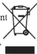
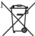
The mark shown to the right is in compliance with the Waste Electrical and Electronic Equipment Directive 2002/96/EC (WEEE).
The mark indicates the requirement NOT to dispose the equipment as unsorted municipal waste, but use the return and collection systems according to local law.
If the batteries, accumulators and button cells included with this equipment, display the chemical symbol Hg, Cd, or Pb, then it means that the battery has a heavy metal content of more than 0.0005% Mercury or more than, 0.002% Cadmium, or more than 0.004% Lead.
ENERGY STAR Information:
To ensure your television is operating at optimal energy efficiency, select [Home] mode during ini activation.
To return to [Home] mode settings, select [Standard] picture mode. [Standard] mode is recommended for normal home use.
Keeping the TV at its factory default settings that meet ENERGY STAR criteria.
Enabling certain features and functionality of LED TV will increase its energy consumption, possibly beyond the limits required for ENERGY STAR qualification.
SRS Trademark Information:

- TruSurround HD is a trademark of SRS Labs, Inc. TruSurround HD technology is incorporated under license from SRS Labs, Inc.
SRS TruSurround HD ^™ creates an immersive, feature-rich surround sound experience from two speakers, complete with rich bass, high frequency detail and clear dialog.
Declaration of RoHS Compliance
This product has been designed and manufactured in compliance with Directive 2002/95/EC of the European Parliament and the Council on restriction of the use of certain hazardous substances in electrical and electronic equipment (RoHS Directive) and is deemed to comply with the maximum concentration values issued by the European Technical Adaptation Committee (TAC) as shown below:
| Substance | Proposed Maximum Concentration | Actual Concentration |
| Lead (Pb) 0.1% < 0.1% | ||
| Mercury (Hg) 0.1% < 0.1% | ||
| Cadmium (Cd) 0.01% < 0.01% | ||
| Hexavalent Chromium ( Cr^6+ ) 0.1% < 0.1% | ||
| Polybrominated biphenyls (PBB) 0.1% < 0.1% | ||
| Polybrominated diphenyl ethers (PBDE) 0.1% < 0.1% |
Certain components of products as stated above are exempted under the Annex of the RoHS Directives as noted below:
Examples of exempted components are:
- Mercury in compact fluorescent lamps not exceeding 5 mg per lamp and in other lamps not specifically mentioned in the Annex of RoHS Directive.
- Lead in glass of cathode ray tubes, electronic components, fluorescent tubes, and electronic ceramic parts (e.g. piezoelectronic devices).
- Lead in high temperature type solders (i.e. lead-based alloys containing 85% by weight or more lead).
- Lead as an allotting element in steel containing up to 0.35% lead by weight, aluminium containing up to 0.4% lead by weight and as a cooper alloy containing up to 4% lead by weight.
Copyright Information
Copyright © ViewSonic® Corporation, 2012. All rights reserved.
ViewSonic, the three birds logo, OnView, ViewMatch, and ViewMeter are registered trademarks of ViewSonic Corporation.
ENERGY STAR ^® is a registered trademark of the U.S. Environmental Protection Agency (EPA).
As an ENERGY STAR ^® partner, ViewSonic Corporation has determined that this product meets the ENERGY STAR ^® guidelines for energy efficiency.
Disclaimer: ViewSonic Corporation shall not be liable for technical or editorial errors or omissions contained herein; nor for incidental or consequential damages resulting from furnishing this material, or the performance or use of this product.
In the interest of continuing product improvement, ViewSonic Corporation reserves the right to change product specifications without notice. Information in this document may change without notice.
No part of this document may be copied, reproduced, or transmitted by any means, for any purpose without prior written permission from ViewSonic Corporation.
Product Registration
To meet your future needs, and to receive any additional product information as it becomes available, please register your product on the Internet at: www.viewsonic.com.
For Your Records
Product Name: VT2755LED
ViewSonic LED TV
Model Number: VS14569-1M
Document Number: VT2755LED-1M_UG_ENG Rev. 1A 12-19-11
Serial Number:
Purchase Date:
Product disposal at end of product life
ViewSonic respects the environment and is committed to working and living green. Thank you for being part of Smarter, Greener Computing. Please visit ViewSonic website to learn more.
USA & Canada: http://www.viewsonic.com/company/green/recycle-program/
Europe: http://www.viewsoniceurope.com/uk/support/recycling-information/
Taiwan: http://recycle.epa.gov.tw/recycle/index2.aspx
IMPORTANT SAFETY INSTRUCTIONS
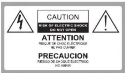

Dangerous Voltage: The lightning flash with arrowhead symbol, within an equilateral triangle, is intended to alert the user to the presence of dangerous voltage within the inside of the product that may be sufficient level to constitute a risk of electric shock to persons.

Instruction: The
exclamation point within an equilateral triangle is intended to alert the user to the presence of important operating and servicing instructions in the literature accompanying the appliance.
Read these instructions completely before using the 1. equipment.
Keep these instructions in a safe place.2.
Heed all warnings.3.
Follow all instructions.4.
Do not use this apparatus near water.5.
Clean with a soft, dry cloth.6.
Do not block any ventilation openings. Install the equipment 7. in accordance with the manufacturer's instructions.
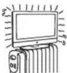
Do not install near any heat sources such 8. as radiators, heat registers, stoves, or other devices (including amplifiers) that produce heat.
Do not attempt to circumvent the safety 9.
provisions of the polarized or grounding-type plug. A polarized plug has two blades with one wider than the other. A grounding type plug has two blades and a third grounding prong. The wide blade and the third prong are provided for your safety. If the provided plug does not fit into your outlet, consult an electrician for replacement of the outlet.
Prevent the power cord from being tread upon or pinched, 10. particularly at the plug, convenience receptacles, and the point where they exit from the device. Be sure that the power outlet is located near the equipment so that it is easily accessible.
Only use attachments/ accessories specified by the 11. manufacturer.
Use only with the cart, stand, tripod, bracket, 12
or table specified by the manufacturer, or sold with the apparatus. When a cart is used, use caution when moving the cart/ apparatus combination to avoid injury from tip-over.

-
Unplug this apparatus when it will be unused for a long period of time.
-
Refer all servicing to qualified service personnel. Servicing
is required when the apparatus has been damaged in any way, such as power-supply cord or plug is damaged, liquid has been spilled or objects have fallen into the apparatus, the apparatus has been exposed to rain or moisture, or the unit does not operate normally, or has been dropped.
USE
AC power Cord
Keep the following guidelines to protect the AC power cord from being damaged. If the AC power cord is damaged, it may result in a fire or an electric shock. Stop using it and ask your dealer or ViewSonic service center to exchange it.
- Do not place the TV where the power cord is subject to wear or abuse.
- Do not pinch, bend, or twist the cord excessively.
- The core lines may be bared and cut, causing a short-circuit, and resulting in a fire or an electric shock.
Do not convert or damage the power cord.
- Avoid power cord being rolled over or rested upon.
- When the power cord is plugged in, do not move the TV.
- Keep the power cord away from heat sources.
- When you disconnect the AC power cord, disconnect it from the wall outlet first.
- When disconnecting the power cord, grasp the plug instead of pulling the power cord.
- Use only an original ViewSonic AC power cord, not other brands.
- Do not use the supplied AC power cord on any other equipment.
Wall outlet
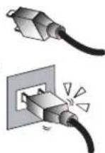
Insert the plug fully into the outlet. If it is loose, do not use it. Doing so may cause arcing and result in a fire. Contact your electrician to change the outlet.
Wiring
For your safety, be sure to unplug the AC power cord when connecting cables.
Take care not to trip on the cables. It may cause damage to the TV set.
Electric shock
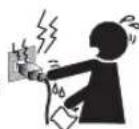
Do not touch the AC power cord or the TV with a wet hand. If you plug/unplug the AC power cord from the TV with a wet hand, it may cause electric shock.
Lightning storms
During a lightning storm, unplug the TV from the wall outlet and disconnect the antenna to prevent damage to the TV.
When not in use
If you will not be using the TV set for long periods of time, the TV set should be disconnected from the AC power outlet to prevent power line surges. The TV set is not disconnected from the AC power source when the TV set is switched off.
To disconnect the TV set completely, unplug from the AC power outlet.
Overloading
This TV set is designed to operate on a 120V AC supply only.
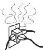
If there are too many appliances connected to the same AC power outlet, it could result in a fire or an electric shock.
Optional equipment
If optional equipment is to be installed, leave some space between optional equipment and the TV set. Picture distortion and/or noisy sound may occur if the TV set is positioned in close proximity to any equipment emitting electromagnetic radiation.
Small accessories
Keep small accessories in a safe place where children are unable to reach.
Magnetic influence
This TV contains a strong magnet in the speaker unit that generates a magnetic field. Keep any items susceptible to magnetic fields away from the speaker.
Sound
If you hear snapping or popping sound comes from the TV continuously or frequently while the TV is operating,
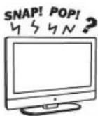
unplug the TV and consult your dealer or service technician. It is normal for some TVs to make occasional snapping or popping sounds, particularly when being turned on or off.
Use in outdoor
This TV is not designed for outdoors installation. Do not expose the TV to rain, as it may result in a fire or an electric shock. Also, do not expose the TV to direct sunlight, as it may heat up and become damaged.
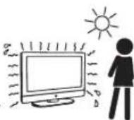
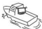
Vehicle, ships and other vessels
Do not install this TV in a vehicle.
Car accidents may cause the TV to fall down and cause injury.

Do not install this TV in a ship or vessel.
If the TV is exposed to seawater, it may cause a fire or damage the TV.
Medical institutions
Do not place this TV in a place where medical equipment is in use. It may cause the medical equipment to malfunction.
Volume adjustment
Adjust the volume to avoid disturbing your neighbors. • Sound carries easily at night. Therefore, we suggest you close the windows or use headphones.
When using headphones, adjust the volume to appropriate • levels, or hearing damage may result.
ANTENNAS
Outdoor antenna grounding
If an outdoor antenna is installed, follow the precautions below. Do not install the outdoor antenna system near of overhead power lines or other electric light or power circuits, or where it can come in contact with such power lines or circuits. WHEN INSTALLING AN OUTDOOR ANTENNA SYSTEM, EXTREME CARE SHOULD BE TAKEN TO KEEP FROM CONTACTING SUCH POWER LINES OR CIRCUITS AS CONTACT WITH THEM IS ALMOST INVARIABLY FATAL Be sure the antenna system is grounded so that it can provide
some protection against voltage surges and built-up static charges.
Section 810 of the National Electrical Code (NEC) in the U.S.A. and Section 54 of the Canadian Electrical Code in Canada provides information with in regard to proper grounding of the mast and supporting structure, grounding of the lead-in wire to an antenna discharge unit, size of grounding conductors, location of antenna discharge unit, connection to grounding electrodes, and requirements for the grounding electrode.
Antenna grounding according to the National
Electrical Code, ANS/NFPA 70
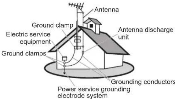
CLEANING
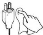
Cleaning the AC power plug
Unplug the AC power plug and clean it regularly. If the plug is covered with dust and gathers moisture, its insulation may deteriorate and result in a fire.
Cleaning the screen surface/ cabinet of the TV set
When cleaning this TV, unplug the AC power cord. If not, it may result in electric shock. Use a dry soft cloth to clean the cabinet of the TV. To remove dust near the screen, wipe it gently with a soft cloth. Stubborn stains may be removed with a cloth slightly dampened with a solution of mild soap and warm water. Never use strong solvents such as thinner or benzine for cleaning. If using a chemically pretreated cloth, please follow the instruction provided on the package. The ventilation holes can accumulate dust over time.

To ensure proper ventilation, we recommend you to remove the dust periodically (once a month) using a vacuum cleaner, while the LED TV is powered off.
Disclaimer
Some chemical cleaners have been reported to damage the screen and/or case of the LCD TV. ViewSonic will not be liable for damage resulting from use of these cleaners.
CARRYING THE TV
Carry the TV as instructed
To prevent dropping the TV and causing serious injury, you must follow these guidelines:
Disconnect all cables before carrying the TV.
Carrying the large size TV requires at least two or three people.
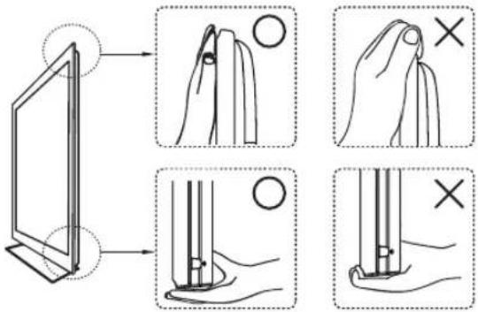
When you carry the TV, place your hands as illustrated and • hold it securely. Do not put stress on the LCD panel and the frame around the screen.
When carrying the TV, do not subject it to shocks, vibration,
or excessive force.
When lifting or moving the TV, hold it securely from the bottom. Place your palm directly under the panel.
VENTILATION
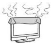
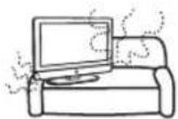
Slots and openings in TV are provided for ventilation. To ensure reliable operation of the TV and to protect it from overheating, be sure these openings are not blocked or covered.
The TV may accumulate dust and get dirty if proper ventilation is not provided. For proper ventilation, follow the following guidelines:
Never install the TV face up, down or • sideways.
Never install the TV turned over or upside down.
Never cover the slots and openings with a cloth or other materials.
Never block the slots and openings by • placing the TV on a bed, sofa, rug or other similar surface.
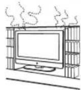
Never place the TV in a confined space, such as a bookcase • or built-in cabinet, unless proper ventilation is provided.
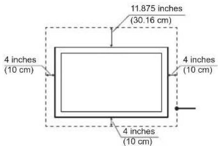
Leave some space around the TV set as shown below. Otherwise, air-circulation may be inadequate and cause overheating, which may cause a fire or damage to the TV set.
Installed on the wall
Installed with stand
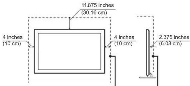
Leave at least this space around the set.
ViewSonic
Do not install the TV set as follows:
Air circulation is blocked. Air circulation is blocked.
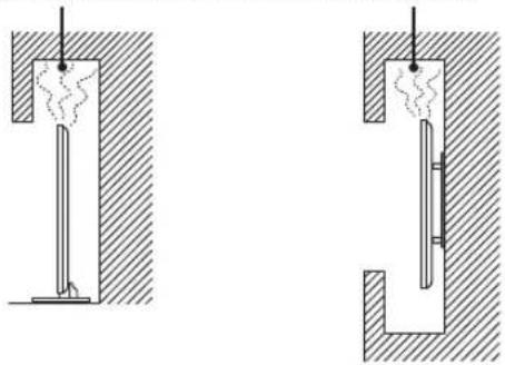
natural_image
Two mechanical cross-section diagrams showing internal components with hatched areas and no visible text or symbolsObjects and ventilation holes
Never push any objects into the slots on the TV cabinet as they may touch dangerous voltage points or short out parts that could result in a fire or an electric shock. Do not place any objects on the TV.
MOISTURE
Moisture and flammable objects
Keep the product away from moisture. Do not expose this appliance to rain or moisture. Do not place objects filled with liquids, such as vases, on the TV.
Do not use power-line operated V sets near water, such as in places like a bathtub, washbowl, kitchen sink, laundry tub, a wet basement, or near a swimming pool, etc. It may cause fire or electric shock.
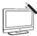
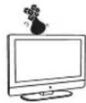
Do not let this TV get wet. Never spill liquid of any kind on the • TV. If water penetrates into the product, unplug the power cord and contact ViewSonic.
Do not operate the TV when wet. It may result in electric shock or damage to the TV.
To prevent fire, keep flammable objects or open flame (e.g. candles) away from the TV.
INSTALLATION
Optional wall mount
To do Wall mount installation, you need a Wall-Mount Bracket. When installing or removing the TV using the Wall-Mount Bracket, be sure to use qualified contractors. If not properly secured during installation or removal from the Wall-Mount Bracket, the TV may fall and cause serious injury.
When installing the TV using a Wall-Mount Bracket, make sure you follow the operating instructions supplied with the Wall-Mount Bracket.
- Attach the brackets supplied with the Wall-Mount Bracket.
- The TV is not designed for hanging from the ceiling. It may fall and cause serious injury.
Placement
The TV should be installed near an easily accessible AC power outlet.
Observe the following to prevent the TV from falling from the stand or wall mount.
- Place the TV on a stable, level surface.
- Do not hang anything on the TV. Do not allow
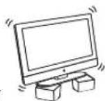
children to climb on the TV.
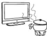
Do not install the TV in places subject to extreme • temperature, such as in direct sunlight, near a radiator, or heating vent. If the TV is exposed to extreme temperature, the TV may overheat and cause deformation of the enclosure or cause malfunction.
Do not install the TV in a place exposed to direct air conditioning.
If the TV is installed in such a location, moisture • may condense inside and may cause a malfunction.
Do not place the TV in hot, oily, humid or • excessively dusty places.
Do not install the TV where insects may enter.
Do not install the TV where it may be exposed to mechanical • vibration.
Do not install the TV in a location where it may spear up, such as on or behind a pillar, or where you might bump your head on it. It may cause injury.
Preventing the TV from toppling over
To prevent the TV from toppling over, secure the TV to a wall or stand.
Placement for watching
We suggest you to watch the TV at a distance of 3-7 times that of the screen height, and not in excessive brightness. It is easy to cause eye fatigue if you watch TV for too long or in a dark room. To obtain clear picture, do not expose the screen to direct illumination or sunlight. Use spot lighting directed down from the ceiling if you can.
LCD SCREEN
Although the LCD screen is made with high precision technology and has effective pixels of 99.99% or more, black dots or bright points or light (red, blue, or green) may appear constantly on the LCD screen. This is a structural property of the LCD panel and is not a malfunction.
The LCD screen is made with high-precision technology. To achieve a high level of performance and picture quality, this TV's backlight setting is set to maximize the brightness of the TV. However, uneven brightness may be observed when the LED TV is viewed in a dark environment without an input source or a blank screen. This is a normal condition, not a malfunction of the TV. To improve this condition, change the Picture mode, Backlight setting, enable the Light Sensor, or turn on the Power management.
Avoid exposing the LCD screen surface to direct sunlight. It is likely to damage the LCD panel.
Do not push or scratch the LCD screen, or place objects on • top of the TV. The image may be uneven or the LCD panel may be damaged.
If the TV is used in a cold place, a smear may occur in the • picture or the picture may become dark. It is not caused by a failure. This condition will improve as the temperature rises.
When still pictures are displayed continuously, ghosting may occur. It should disappear after a short period of time.
The screen and cabinet get warm when the TV is in use. This is a normal condition.
- Spraying insect repellent with volatile material on the screen
will cause damage.
- Do not make prolonged contact with rubber or plastic material.
Broken pieces
Do not throw anything at the TV.
Doing so may break the screen glass and cause serious injury.
If the surface of the TV cracks, unplug the AC power cord before touching the TV. Otherwise electric shock may result.

Handling of broken glass and liquid crystal leakage
If the LCD panel gets damaged, crystalline liquid leakage may occur, or scattered broken glass may result. Do not touch broken glass or crystalline liquid which is toxic, with bare hands as cuts, poisoning or skin irritation may occur. Also do not glass fragments or leaked crystalline liquid get into your eyes or mouth. Should either contacted your eyes or mouth, rinse the contacted area thoroughly with water and consult your doctor.
SERVICING
Do not attempt to repair the TV yourself, since opening the cabinet may expose you to dangerous voltage or other hazards. Ask qualified service personnel to do the servicing for your TV.

Replacement parts
When replacement parts are required, be sure the service technician certifies in writing that he/she has used replacement parts specified by the manufacturer that have the same characteristics as the original parts. Unauthorized substitutions may cause a fire, an electric shock or other hazards.
Safety check
Upon completion of repairs to the TV, ask the service technician to perform routine safety checks (as specified by the manufacturer) to determine that the TV is safe for operating, and to so certify.
Ask a qualified service technician to dispose of the TV.
Package Contents
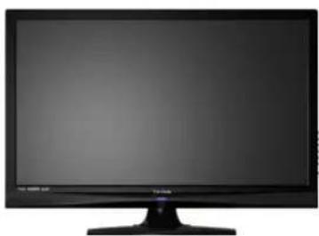
Please make sure the following items are included with your LCD TV. If any items are missing, please contact your dealer.
natural_image
Front view of a black flat-screen computer monitor (no visible text or symbols)LCD TV
natural_image
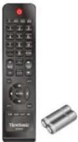
Retro television remote with control panel and two cylindrical batteries (no visible text or symbols)Remote Control with batteries
Power Cord
![ViewSonic® VITOMI-ED LOG TV Editor-in-Chief: [1] K. H. M. R. A. B. C. [2] J. S. L. E. F. G. [3] A. T. W. X. Y. Z. [4] A. P. T. U. V. W. [5] A. R. T. V. X. [6] A. S. T. W. Y. [7] A. T. W. X. [8] A. S. T. W. [9] A. T. W. [10] A. T. W. [11] A. T. W. [12] A. T. W. [13] A. T. W. [14] A. T. W. [15] A. T. W. [16] A. T. W. [17] A. T. W. [18] A. T. W. [19] A. T. W. [20] A. T. W. [21] A. T. W. [22] A. T. W. [23] A. T. W. [24] A. T. W. [25] A. T. W. [26] A. T. W. [27] A. T. W. [28] A. T. W. [29] A. T. W. [30] A. T. W. [31] A. T. W. [32] A. T. W. [33] A. T. W. [34] A. T. W. [35] A. T. W. [36] A. T. W. [37] A. T. W. [38] A. T. W. [39] A. T. W. [40] A. T. W. [41] A. T. W. [42] A. T. W. [43] A. T. W. [44] A. T. W. [45] A. T. W. [46] A. T. W. [47] A. T. W. [48] A. T. W. [49] A. T. W. [50] A. T. W. [51] A. T. W. [52] A. T. W. [53] A. T. W. [54] A. T. W. [55] A. T. W. [56] A. T. W. [57] A. T. W. [58] A. T. W. [59] A. T. W. [60] A. T. W. [61] A. T. W. [62] A. T. W. [63] A. T. W. [64] A. T. W. [65] A. T. W. [66] A. T. W. [67] A. T. W. [68] A. T. W. [69] A. T. W. [70] A. T. W. [71] A. T. W. [72] A. T. W. [73] A. T. W. [74] A. T. W. [75] A. T. W. [76] A. T. W. [77] A. T. W. [78] A. T. W. [79] A. T. W. [80] A. T. W. [81] A. T. W. [82] A. T. W. [83] A. T. W. [84] A. T. W. [85] A. T. W. [86] A. T. W. [87] A. T. W. [88] A. T. W. [89] A. T. W. [90] A. T. W. [91] A. T. W. [92] A. T. W. [93] A. T. W. [94] A. T. W. [95] A. T. W. [96] A. T. W. [97] A. T. W. [98] A. T. W. [99] A. T. W.](/content/2026/05/1065732/images/c870a3bfe8fc220fdd8f7ed6b790ecbd1d6bc0f2cfe5a480727ad25b002cb220.jpg)
ViewSonic User Guide
Installing the LCD TV
Installing the Stand
natural_image
Black plastic tray component labeled 'Figure 1' (no other text or symbols visible)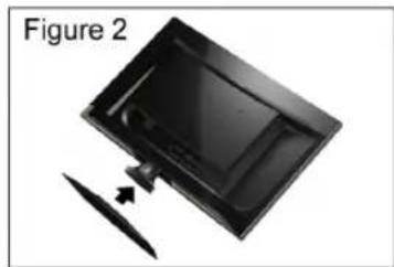
natural_image
Diagram of a device with a blade and arrow, labeled 'Figure 2' (no text or symbols on the diagram itself)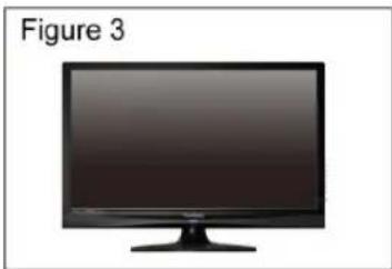
natural_image
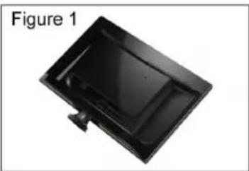
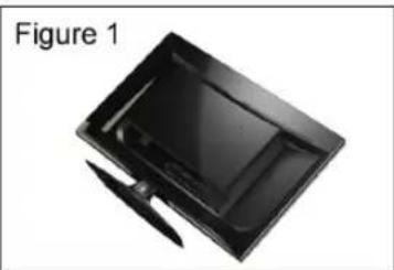
Illustration of a flat-screen monitor labeled 'Figure 3' (no text or symbols on the device itself)- Lay the TV flat on a table with the LCD screen face down. To prevent the TV from being scratched, put a piece of soft cloth on the table on which the screen will be set. (see Figure 1)
- Unpack the stand, one hand hold the TV and one hand pull stand with arm together. (see Figure 2)
- Stand the TV up. (see Figure 3)
Disconnecting the Stand
- Lay the TV flat on a table with the LCD screen face down. To prevent the TV from being scratched, put a piece of soft cloth on the table on which the screen will be set. (see Figure 1)
- Press on four corners of the hinge cover and pull as arrow direction to disengage the hinge cover. (see Figure 2)
- Remove the 4 screws on the hinge, then pull up the stand slowly. (see Figure 3)
- Then connect the hinge cover to the back cover like shown below. (see Figure 4)
- Then, you shall successfully uninstall the stand. (see Figure 5)
natural_image
Black plastic tray with a knife inserted, labeled 'Figure 1' (no other text or symbols)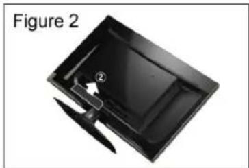
natural_image
Black plastic tray with a labeled component and arrow indicator (no text or symbols on the tray itself)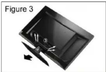
natural_image
Diagram of a device with arrows indicating movement or force, labeled 'Figure 3' (no text or symbols on the diagram itself)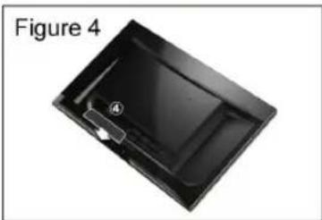
natural_image
Black plastic tray with a labeled component and arrow indicator (no text or symbols on the tray itself)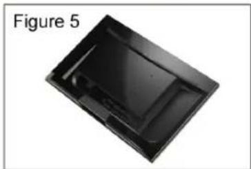
natural_image
Black plastic tray or cover with a label 'Figure 5' on the left (no other text or symbols visible)Mounting ViewSonic LCD TV to the wall
The LCD TV can be used in a free standing position or wall-mounted. Before installing the product to the wall, please consider the following guidelines:
- Read the Important Safety Instructions, at the start of this manual.
- Do not install in a moist or wet environment. This equipment is intended for indoor use.
- Do not install near heat source, or strong magnetic fields.
- Use only ViewSonic approved wall-mounting brackets to support the LCD TV weight.
- Before attaching the wall mount plate to the back cover, ensure the product is working.
- If your LCD TV is already set up for free-standing operation, you need to first remove the stand before mounting the device to the wall.
To attach the wall-mount bracket to LCD TV safely, please use the following guidelines:
- Disconnect the power and any other cables that might hinder moving the LCD TV.
- Set the LCD TV on a table or work surface, placing the screen face down on a towel or woolen blanket to protect the screen surface from damage while installing plate.
- Before installing the LCD TV on the wall, ensure you have recorded the product serial number on page (i) of the User Guide, as you will need the serial number to request service should there be a service need.
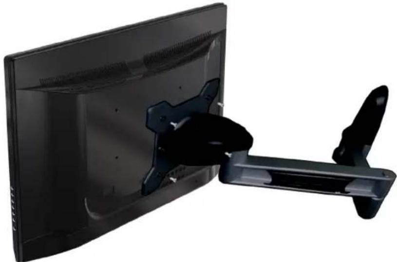
• Install the wall mount plate to the LCD TV using screws NO LONGER than 10mm, as longer screws found in universal (non-ViewSonic) wall mount kits may damage the power supply causing the unit to fail. The wall-mount screw type is M4 x L10.
natural_image
Side view of a black wall-mounted monitor with a black cable or connector attached (no text or symbols visible)- Mount the wall mount bracket to the wall ensuring use of proper screws to support the installation. Ensure there is at least 3cm of space surrounding any air-vents of your LCD TV to allow adequate cooling during operation.
- Hang the LCD TV wall mount plate to the wall mount bracket, completing installation. Enjoy your ViewSonic LCD TV!
Wall Mount Kit Specifications (VESA)
When attaching to other building materials, please contact your nearesr dealer.
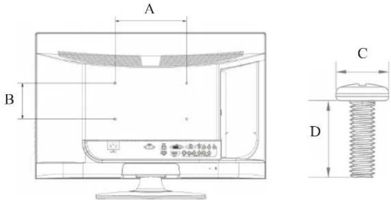
| Product Family inch VESA Spec. (A x B) Standard Screw (C x D) Quantity | ||||
| LCD TV | 16 75 x 75 mm M4 x L10 4 | |||
| 19 ~ 24 100 x 100 mm M4 x L10 4 | ||||
| 26 ~ 27 200 x 100 mm M4 x L10 4 | ||||
| 32 ~ 37 400 x 100 mm M6 x L10 4 | ||||
| 42 ~ 47 600 x 200 mm M6 x L10 4 | ||||
| 52 400 x 200 mm M6 x L10 4 | ||||
- ViewSonic provides the standard dimensions for wall mount kits as shown in the table above.
- Please use the following ViewSonic TVs only with the following wall-mount kit.
| ViewSonic Wall-Mount kit model | WMK-10 |
Use with other Wall-Mount kit may cause instability and possibly result in injury. To find the perfect mount for VT2755LED, please browse www.viewsonic.com or call our service team: United States 1-800-688-6688, Canada 1-866-463-4775.
- When purchasing our wall mount kit, a detailed install manual and all parts necessary for assembly are provided.
- Do not use the screws that longer than the standard dimension, as they may cause damage to the inside of the TV set.
Front View of the Product
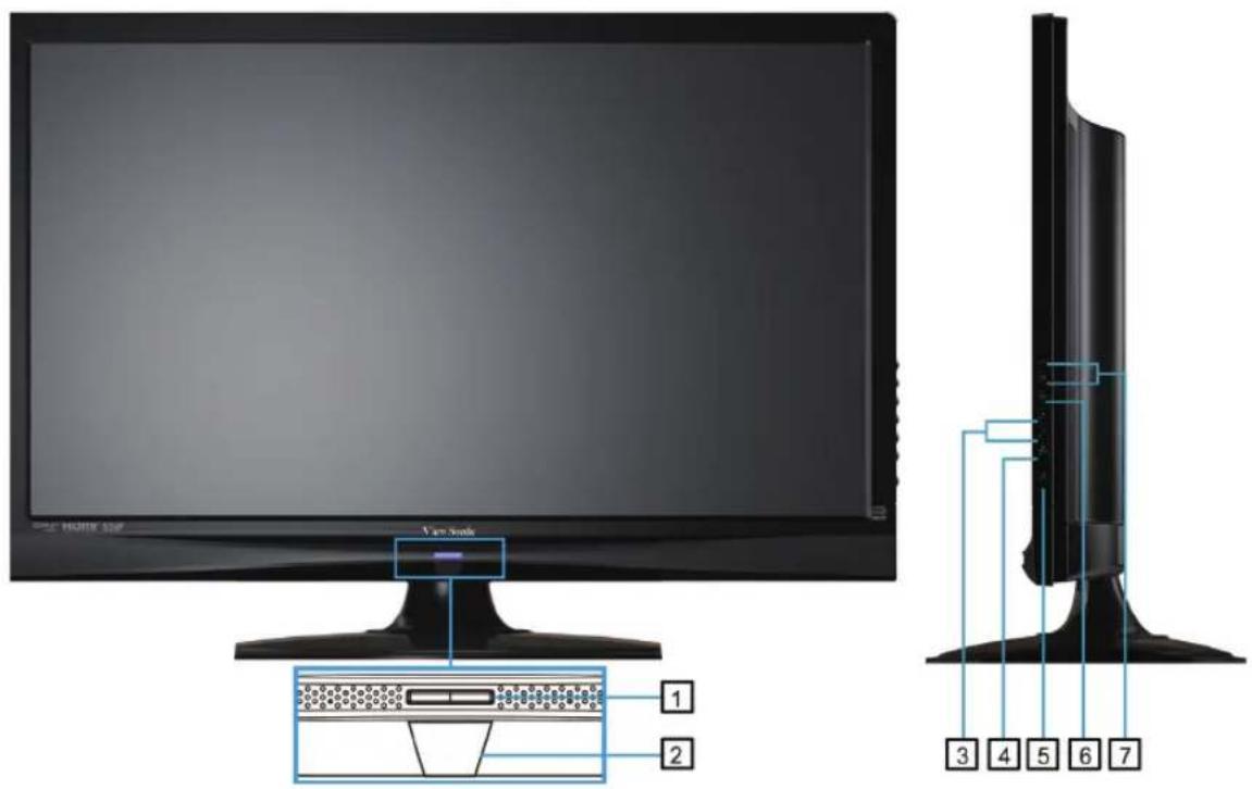
| Item Description | |
| 1 Power LED Indicator | Lights up in blue when the TV is turned on. Lights up in orange when the TV is in standby mode. |
| 2 Remote Control Receiver | Receives IR signals from the remote control. |
| 3 CH Up / Down | Channel up / down when source is TV, or select a control while in OSD menu. |
| 4 INPUT | Select input source. |
| 5 Power ON/OFF button | Turn the power on from standby mode or turn the power off to return to the standby mode. |
| 6 MENU | Turn OSD menu ON/OFF. |
| 7 Volume Up / Down | Increase / Decrease sound volume or adjust a highlighted control while in OSD menu. |
Rear View of the Product
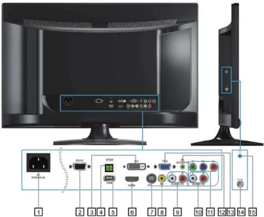
| Item Description | |
| 1 Power (AC input) | Plug-in the supplied AC Power cord and connect to the AC input power source. |
| 2 RS232 signal input | This port is for the service technician's use. |
| 3 DVI signal input | Connect this port to the DVI output of PC device. |
| 4 SPDIF Optical output | Connect this port to the SPDIF input of A/V device. |
| 5 USB | Connect to your USB devices, such as USB flash drive. |
| 6 HDMI Input Terminal | Connect this port to the HDMI output of PC device. |
| 7 S-Video input | Connect the S-Video cable from the compatible device to this connector on the rear panel of the LCD TV. |
| 8 Composite Video input | Connect this jack to the composite video output connectors on your A/V equipment. |
| 9 AV/ S-Video Audio input (left/ right) | Connect the Audio in cable for AV/ S-Video from this jack to the corresponding connectors on your A/V device. |
| 10 YPbPr signal Audio input (left/ right) | Connect the Audio in cable for YPbPr from this jack to the corresponding connectors on your A/V device. |
| 11 YPbPr signal input | Connect this port to the YPbPr output of A/V device. |
| 12 PC Audio input | Connect the RGB Audio Out on your computer to the RGB Audio on the rear of the LCD TV. |
| 13 VGA signal input | Connect a 15-pin D-sub RGB cable to the RGB output of your computer and the other end to the RGB input on the rear of the LCD TV. |
| 14 TV Input Jack | Connect this jack to your Cable or VHF/UHF antenna. |
| 15 Headphone Jack | Connect to your headphones. By connecting the headphones, you can listen to the sound from the TV on headphones.* If you connect the headphones, the TV speakers will be muted. |
Connecting the LCD TV
Cable System or VHF/UHF Antenna System
Enjoy the high-definition and standard-definition digital programming along with standard-definition analog programming.
[Non-Text]
- This TV is capable of receiving unscrambled digital programming for both cable and external VHF/UHF antenna.
- We strongly recommend that you connect the antenna/cable input using a 75-ohm coaxial cable (not supplied) to ensure the best picture quality.
Cable or VHF/UHF

Cable System and VHF/UHF Antenna System
Use an optional A-B RF switch (not supplied) to switch between the cable and antenna programming, as shown below.

flowchart
graph LR
    A["Cable"] --> B["A-B RF switch"]
    C["Antenna"] --> B
    B --> D["Rear of TV"]
    D --> E["VHF/UHF/CABLE input"]
[Non-Text]
- Remember to set the TV/CATV setting in the TV menu to Air or Cable for the type you choose.
HD Cable Box/HD Satellite Box
You can also enjoy high-definition programming by subscribing to a high-definition cable service or a high-definition satellite service. For the optimum picture quality, be sure to connect this device to your TV via the HDMI or component video (with audio) input on the back of your LCD TV.
HDMI Connection
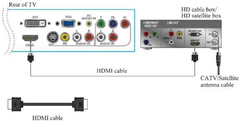
DVI Connection
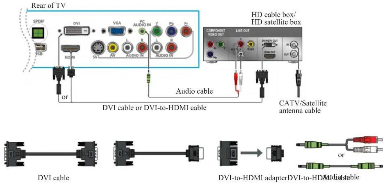

- If the equipment has a DVI jack and not an HDMI jack, connect the DVI jack to the DVI jack [3] (with DVI cable) or HDMI jack [6] (with DVI-to-HDMI cable or adapter), and connect the audio jack to the AUDIO In jacks of PC Audio input [12].
- DVI jack [3] jack mainly supports PC signal, with audio connected from PC Audio input [12]. HDMI jack [6] jack is recommended for video signal.
YPbPr or Component Connection
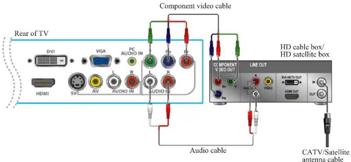

- YPbPr provides better picture quality than the S-Video or the AV connection.
Programming your Cable or Satellite Box remote
Refer the user manual from your service provider to determine the setting.
If it requires:
- 3 digits, please try "566", "565", "556", or "688". It usually works with DISHNetwork.
- 4 digits, please try "0054". It usually works with Cox.
- 5-digits, please try "11454", "11054", or "10690". It usually works with DIRECTV.
SD DVD Player
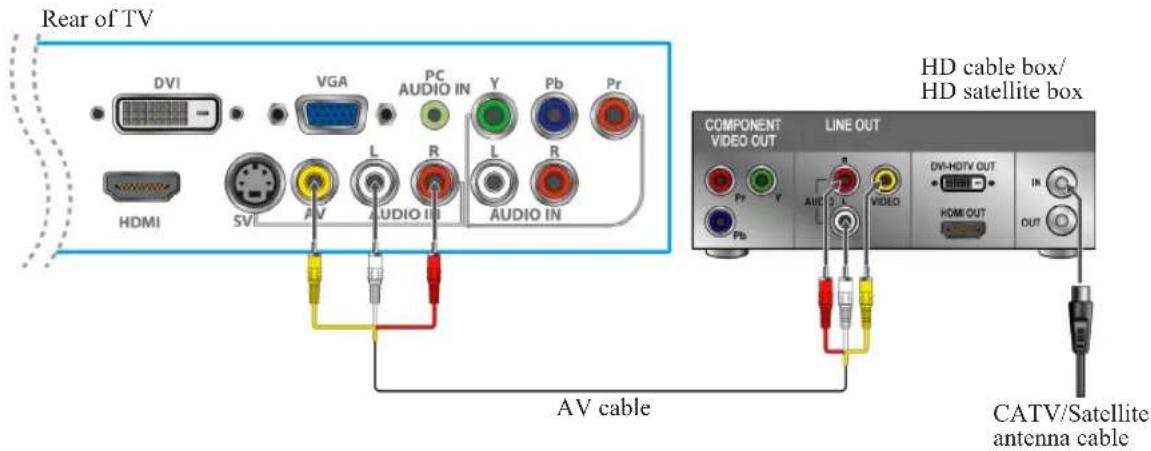
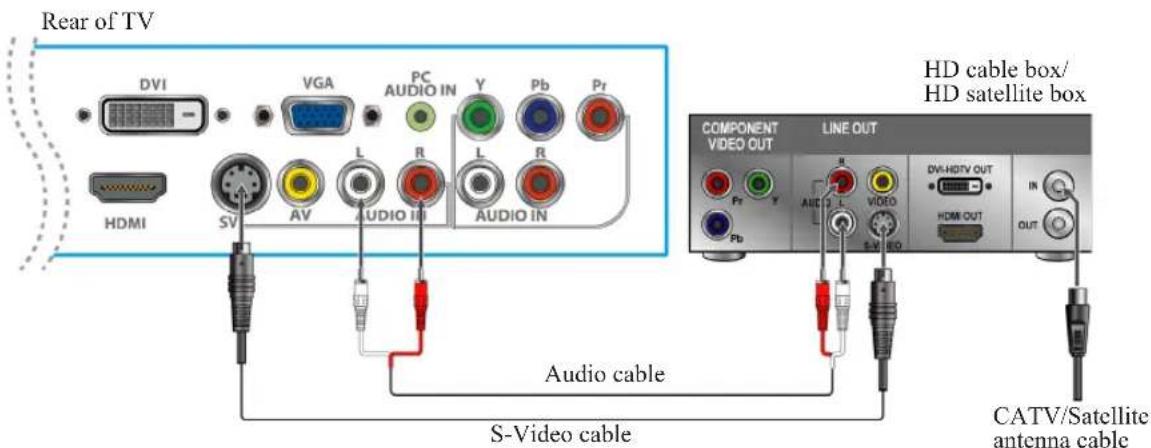
AV or S-Video Connection
Personal Computer
Use the LCD TV as the monitor of your computer.
The picture below shows the connection for PC. The LCD TV can also be connected to PC with DVI or VGA output.
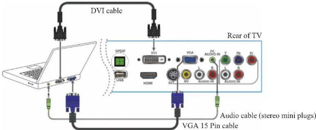

- Connect the PC IN jack to the PC using a 15-pin cable and audio cable.
- If the PC is connected to TV and no signal has been input from PC for more than 5 seconds, the TV will enter standby mode automatically.
PC Timing Reference Chart
| Mode Aspect Ratio Handling Compatible Input | |||
| Standard Resolution FS*Full-Screen RGB | |||
| 720 x 400 @ 70Hz 1920x1080 Yes | |||
| VESA | 640 x 480 @ 60Hz 1920x1080 Yes | ||
| VESA | 640 x 480 @ 75Hz 1920x1080 Yes | ||
| VESA | 800 x 600 @ 60Hz 1920x1080 Yes | ||
| VESA | 800 x 600 @ 75Hz 1920x1080 Yes | ||
| MAC | 832 x 624 @ 75Hz 1920x1080 Yes | ||
| VESA | 1024 x 768 @ 60Hz 1920x1080 Yes | ||
| VESA | 1024 x 768 @ 75Hz 1920x1080 Yes | ||
| VESA | 1280 x 1024 @ 75Hz 1920x1080 Yes | ||
| VESA | 1360 x 768 @ 60Hz 1920x1080 Yes | ||
| VESA | 1440 x 900 @ 60Hz 1920x1080 Yes | ||
| VESA | 1680 x 1050 @ 60Hz 1920x1080 Yes | ||
| VESA | 1920 x 1080 @ 60Hz 1920x1080 Yes | ||

- This TV's PC VGA input does not support interlaced signals.
- For the best picture quality, we recommend that you use the signals (boldfaced) in the above chart with a 60 Hz vertical frequency from a personal computer.
- Preset Timing Mode (Pre-adjusted to GTF® 1920 x 1080 @ 60 Hz)
Note: Simultaneously press "MENU" and "CH▼" keys on TV panel to switch between similar PC timings.
Similar PC Timing on list below:
• 640 x 400 @ 70Hz / 720 x 400 @ 70Hz
• 1280 x 768 @ 60Hz / 1360 x 768 @ 60Hz
• 1680 x 1050 @ 60Hz / 1400 x 1050 @ 60Hz
• 1600 x 900 @ 60Hz / 1440 x 900 @ 60Hz
Using the TV Features
Remote Control and TV Controls
Inserting Remote Control Batteries
- Remove the battery cover by pulling then lifting the knob on the cover.
- Insert the batteries, corresponding to the (+) and (-) markings on the battery compartment.
- Reattach the battery cover.
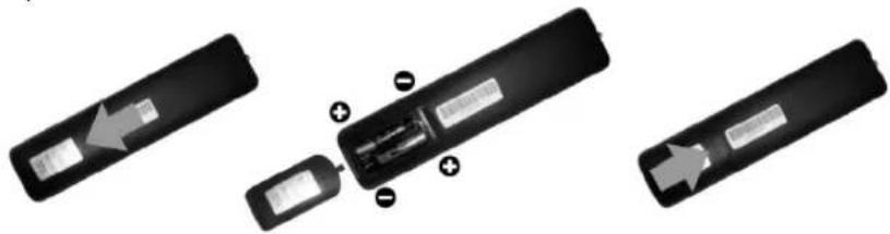
natural_image
Three views of a black remote control device showing internal components and battery casing (no text or symbols visible)
CAUTION
- Only use the specified AAA batteries.
- Do not mix new and old batteries. This may result in creaking or leakage, which may pose a risk of fire or lead to personal injury.
- Insert batteries according to (+) and (-) markings. Inserting the batteries incorrectly may result in leakage, which may pose a risk of fire or lead to personal injury.
- Dispose of the battery in accordance with local laws and regulations.
- Keep the batteries away from children or pets.
- When the remote control will not be used for an extended period, remove the batteries.
Remote Control and TV Controls
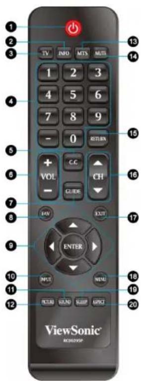
Buttons located at the side of the LCD TV will operate the same as these buttons on the remote control.
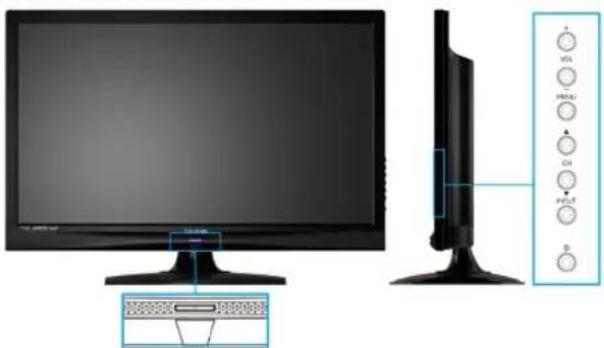
natural_image
Illustration of a flat-screen monitor and its side-mounted control panel with labeled buttons (no text or symbols on the devices themselves)Button Description
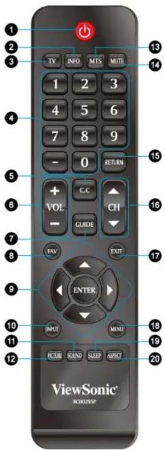
1 POWER Press this button to turn the power on from standby mode. Press it again to return to the standby mode.
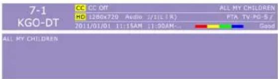
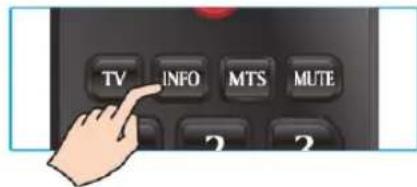
2 INFO Press this button to display the current state of the LCD TV.
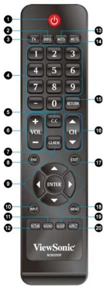
| Button Description | |
| 3 TV | Press to direct to TV source when in any other source. |
| 4 0~9, -number buttons | Press 0~9 and “-” to select a channel. After you input the channel numbers, press ENTER button to direct to the channel immediately, or wait for 3 seconds to change automatically. |
| 5 C.C | Press to select the Closed Caption menu in the TV , AV, S-video mode. |
| 6 - VOL + | Press to adjust the volume. |
| 7 GUIDE | Press to display the Electronic Program Guide (EPG). It contains the program information for the channel you’re watching.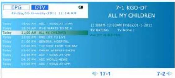 * The picture here shows an example of the GUIDE screen in a DTV source. * The picture here shows an example of the GUIDE screen in a DTV source. |
| 8 FAV | Press this button to show Favorite List and select your favorite channels that have already been stored.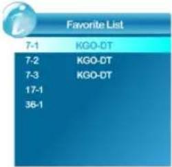 * To preset favorite channels, use the Favorite item in the Channel menu.(see page 17) * To preset favorite channels, use the Favorite item in the Channel menu.(see page 17) |
| 9 ▲▼◀▶/ENTER buttons | Press these buttons to navigate the OSD menus.▲/▼ is for menu and function select, and ◀/▶ is for function adjustment.ENTER: Enter the function setting. |
Button Description
| 10 INPUT | Press to display the INPUT source list and select the source with ▲/▼ buttons. To confirm the selection, press ENTER.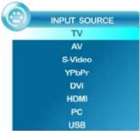 |
| 11 SOUND | Press this button to select between the sound modes of Standard, Music, Movie, Sports or Personal. |
| 12 PICTURE | Press this button to select between the picture modes of Standard, Dynamic, Soft, or Personal. |
| 13 MTS | Press this button to choose the available sound output that is preset by TV broadcasting station.(EX: Mono, Stereo, SAP) |
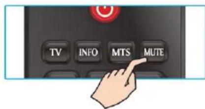
| 14 MUTE | Press to turn off the sound. To restore the sound, press this button again, or press the VOL+/-button. |
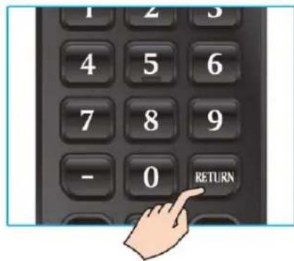
| 15 RETURN | Press to return to previous channel. |
| 16 ▼ CH ▲ | Press to change the channels up or down. |
| 17 EXIT | OSD exit |
| 18 MENU | Press to turn the OSD (On-Screen Display) menu on. |
| 19 SLEEP | Press repeatedly to set the off timer. The function is used to automatically shut off the LCD TV after a preset period of time passed. There are several times for choice – Off, 5 Min, 10 Min, 15 Min, 30 Min, 45 Min, 60 Min, 90 Min, 120 Min, 180 Min, 240 Min. |
| 20 ASPECT | Press this button repeatedly to select the screen size. You can select from Normal, Movie Scale, Zoom In, and 4:3. |
Operation
Turning the TV On and Off
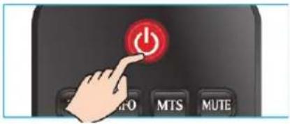
Press the POWER button on the remote control.
You can also use the Power button on the side of the panel.
* If there is no input signal within 15 minutes, TV will be turned off automatically.
Initial Setup
(Setup Wizard only appears when first turning the TV on and without channel scanning.)
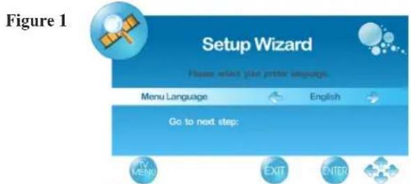
- Press the POWER button on the remote control. The Setup Wizard window will be display.
- Press ◀ or ▶ to select OSD language, then press ENTER or ▼ to confirm the selection, and press ▶ or ENTER to go to next step. To return to the previous page, press MENU.(See Figure1)
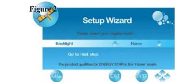
- Press ◀ or ▶ to select your display mode from *Home, Medium, Low or High, then press ENTER or ▼ to confirm the selection, and press ▶ or ENTER to go to next step. To return to the previous page, press MENU. (See Figure2)
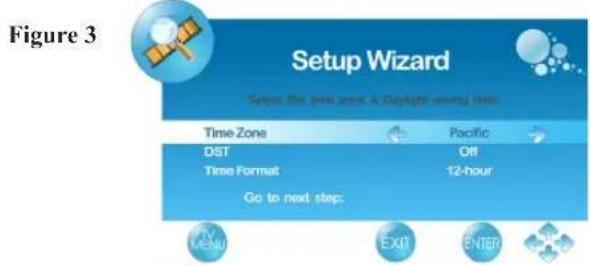
* For normal home use, we suggest that you select "Home" to achieve energy saving. - Select Time Zone of your location. To press ▼ to setup DST (Daylight Saving Time) and select On or Off with ◀ or ▶, according to the time zone of your area. To press ▼ to setup Time Format, and select 12-hour or 24-hour with ◀ or ▶, then press ENTER or ▶ to continue. (See Figure3)
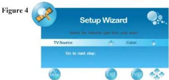
- Select TV Source from Air or Cable, then press ENTER to continue. (See Figure4)
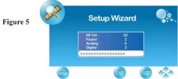
- The Initial Setup will be completed after Cannel scanning is finished. To interrupt the scanning, press MENU at any time. (See Figure5)
Changing Channels
- Using Channel Buttons
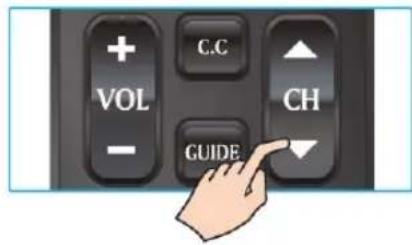
Press ▼CH▲ button to change channels, and the TV changes channels in sequence. You will see all channels that have been memorized. Channels erased or not memorized will not be shown.
- Using Number Buttons
(1) ATV
The “-” button has no function in ATV mode. Directly press the number buttons to select channels.
(2) DTV
Use “-” button to select the sub channel in DTV.
Ex: Your desired number is 80-3.
Press 8 → press 0 → press “-” → press 3.
* Return to the previous channel, press RETURN button.
Adjusting the Volume
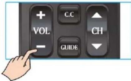
Press VOL +/- to adjust volume.
To turn off the volume, press MUTE.
To restore volume, press MUTE again, or press
VOL +/- directly.
Viewing the Displayed Information
To display the current information of the LCD TV:
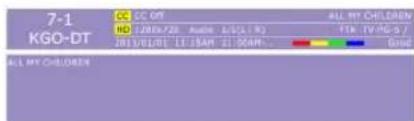
Press INFO, and the current state will be displayed on the screen. (It shows all or some of the information about Input, Channel, Resolution, Audio Type, etc., depending on what input source it is in)
* The picture here shows an example of the INFO screen in a DTV source.
Storing Channels into Memory
-
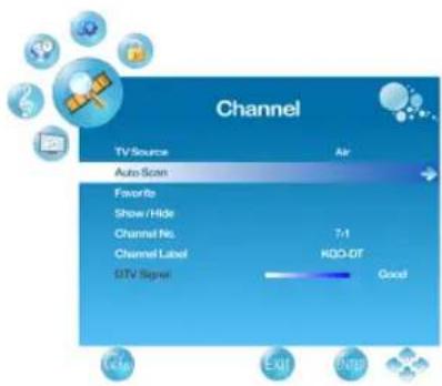
Press the MENU button to display the OSD main menu.
-
Press ◀ or ▶ to select the "CHANNEL" menu, then press ENTER or ▼ to enter the menu. Press ▲ or ▼ to select "TV Source", and use ◀ or ▶ to select the antenna connection to "Air" or "Cable".
Air: RF signal programs by "Air".
Cable: RF signal programs by "Cable".
-
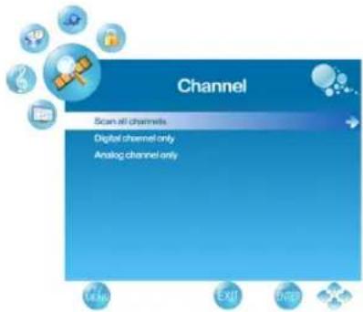
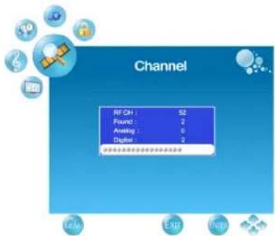
Press ▲ or ▼ to select "Auto Scan", then press ▶ to enter.
-
Press ▲ or ▼ to select “Scan all channels”, “Digital channel only”, or “Analog channel only” and press ▶ to perform Auto Scan function.
To stop scanning, press MENU at any time.
- The Auto Scan screen will be shown, and after it is done, the screen will return to the first found channel.
Selecting the Input Source
To select the TV or other external input sources connected to the TV.
-
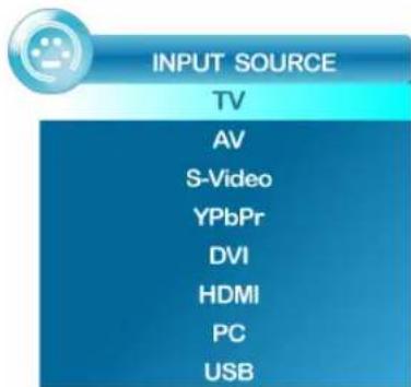
Press the INPUT button on the remote control.
-
Press ▲ or ▼ to select the required input source between TV, AV, S-Video, YPbPr, DVI, HDMI, PC or USB. (When in USB input source, the system only supports JPEG and MP3 image files.)
-
To confirm the selection, press ENTER.
Favorite Channel Setting
To set your favorite channel into memory:
-
Press the MENU button to display the OSD main menu.
-
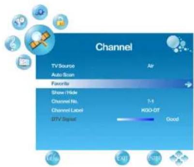
Press ◀ or ▶ to select the "CHANNEL" menu, then press ENTER or ▼ to enter the menu. Press ▲ or ▼ to select "Favorite", then press ▶ button to enter "Favorite" setting.
-
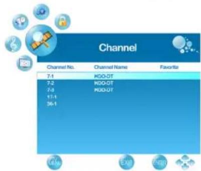
Press ▲ or ▼ to select the channel you'd like to be your favorite channel.
Press ENTER to confirm your selection.
-
To cancel the selection, Press ENTER again on the selected channel.
-
Press MENU to exit.
* To view your favorite channels, press FAV button to show Favorite List and select your favorite channels that have already been stored.
Adding/Erasing Channel
When the channel is erased, it will not appear on the screen when you browse the channels with ▼CH▲ button. To see the channel again, you must add the channel or perform the “Auto Scan” (page 16) function again.
- Press the MENU button to display the OSD main menu.
-
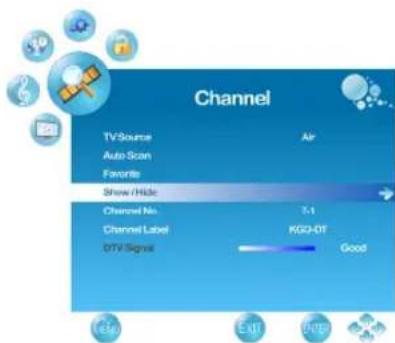
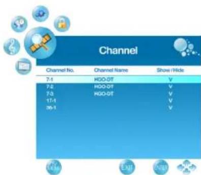
Press ◀ or ▶ to select the “CHANNEL” menu, then press ENTER or ▼ to enter the menu. Press ▲ or ▼ to select “Show/Hide”, then press ▶ button to enter “Show/Hide” setting.
-
Press ▲ or ▼ to select the channel you want to Show/ Hide, and check or uncheck it with ENTER button.
-
Press MENU to exit.
Channel Name Setting
To edit a name for the current channel:
- Press the MENU button to display the OSD main menu.
- Press ◀ or ▶ to select the "CHANNEL" menu, then press ENTER or ▼ to enter the menu.
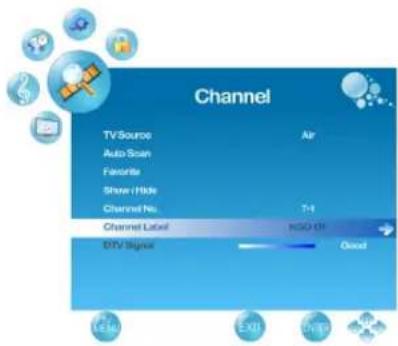
- Press ▲ or ▼ to select "Channel No.", then press ◀ or ▶ to select the channel you want to edit the name.
- Press ▲ or ▼ to select "Channel Label", then press ▶ button to enter "Channel Label" setting.
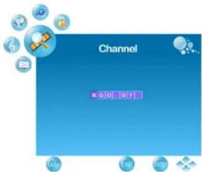
- Use ▲ or ▼ to choose letters or signs, ◀ or ▶ to move forward or backward.
- After you input the channel name, press MENU or ENTER to complete the setting.
- Press MENU to exit.
Using the Parent Controls
- Press the MENU button to display the OSD main menu.
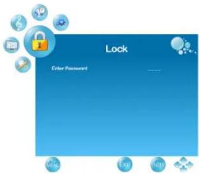
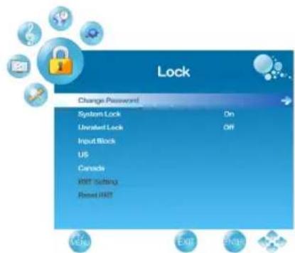
- Press ◀ or ▶ to select the "LOCK" menu.
- Press ENTER or ▼ to enter Password.
- Enter the password. (The default password is 0000)
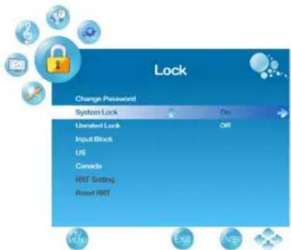
- Move to "System Lock", and select "On" to enable the detailed settings.
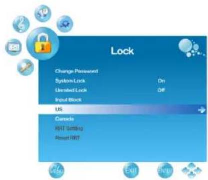
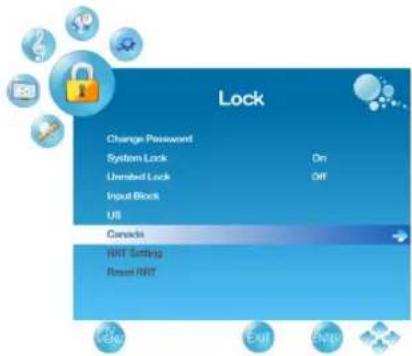
- Move to "US" or "Canada" rating system.
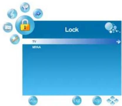
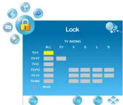
US: Press ▶ to set TV or MPAA ratings.
(1) TV
-
Press ▲ or ▼ to select "TV", then press ▶ to enter "TV" rating system setting.
-
Press ▲ or ▼ to select your desired TV ratings level.
The following screen will allow you to customize the following TV ratings:
TV-Y (all children)
TV-Y7 (older children)
TV-G (general audience)
TV-PG (guidance suggested)
TV-14 (strongly cautioned)
TV-MA (mature audience)
You can also customize the TV ratings for the following content:
ALL (All types content)
FV (fantasy violence)
V (violence)
S (sexual situations)
L (adult language)
D (sexual dialog)
-
Press ENTER to set or reset each area.
-
Press MENU to exit.
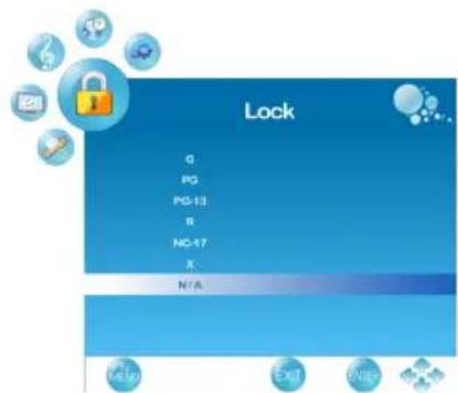
(2) MPAA
-
Press ▲ or ▼ to select "MPAA", then press ▶ to enter "MPAA" rating system setting.
-
Press ▲ or ▼ to select your desired MPAA ratings level.
The MPAA ratings level are defined as following: G (general audience)
PG (parental guidance suggested)
PG-13 (recommended for children 14 years of age or older)
R (mature audience)
NC-17 (no one under 17 years of age)
X (adult audience only)
N/A (not applicable)
-
Press ▲/▼ to set or reset each area.
-
Press MENU to exit.
Canada: Press ▶ to set Canadian English and French ratings.
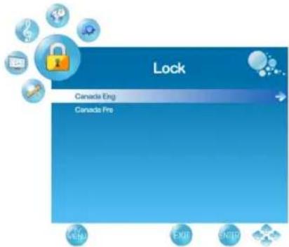
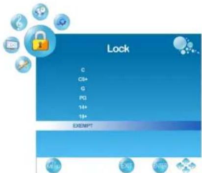
(1) Canadian English
- Press ▲ or ▼ to select "Canada Eng".
- Press ▶ to enter.
- Press ▲ or ▼ to select your desired Canadian English rating level.
The Canadian English rating levels are defined as following:
C (children)
C8+ (children eight years and older)
G (general programming, suitable for all audiences)
PG (parental guidance)
14+ (viewers and older)
18+ (adult programming)
EXEMPT (exempt)
- Press ▲/▼ to set or reset each area.
- Press MENU to exit.
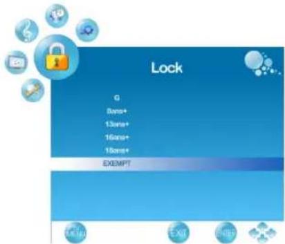
(2) Canadian French
- Press ▲ or ▼ to select "Canada Fre".
- Press ▶ to enter.
- Press ▲ or ▼ to select your desired Canadian French rating level.
The Canadian French rating levels are defined as following:
G (genenral)
8ans+ (children eight years and older)
13ans+ (not appropriate for children of less than 13 years)
16ans+ (not appropriate for children of less than 16 years)
18ans+ (reserved to adults)
EXEMPT (exempt)
- Press ▲/▼ to set or reset each area.
- Press MENU to exit.
To Block Unrated Movie or TV Programs
-
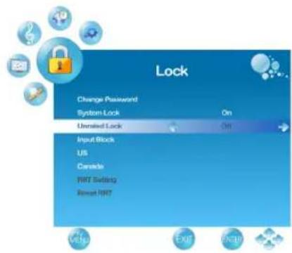
Press ▲ or ▼ to select "Unrated Lock", then press ◀ or ▶ to select "On" or "Off". When "On" is selected, all programs that are not rated will be blocked.
-
Press MENU to exit.
To Set Rating Region Table
RRT Setting defines the rating standard for a particular geographic region and/or country.
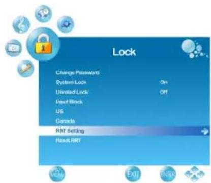
- Press ▲ or ▼ to select "RRT Setting", then press ▶ to enter RRT setting.
- Select each adjustable setting with ▲ or ▼, then press ◀ or ▶ to select the sub-selection.
- Press MENU to exit.
* The picture here only shows an example of the content of RRT Setting. However, the selections and subselections of RRT Setting may be different in your OSD menu according to the local broadcasting system.
* To reset RRT setting, move to "Reset RRT", and press ▶ to reset.
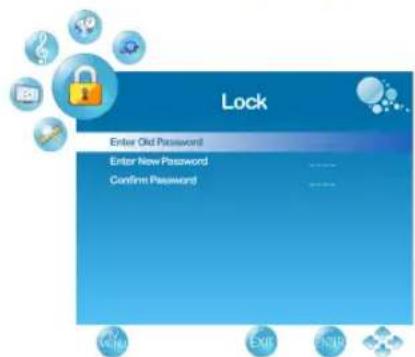
To Change Password
- Press ▲ or ▼ to select “Change Password”, then press ▶ to enter “Change Password” setting.
- Move to "Enter Old Password", then enter the old password with number keys.
- Enter your new password on "Enter New Password".
- Enter your new password again on "Confirm Password".
After you complete the last step, the screen will return to the top page of LOCK menu. If so, the password has been changed successfully.
To block by Input Source
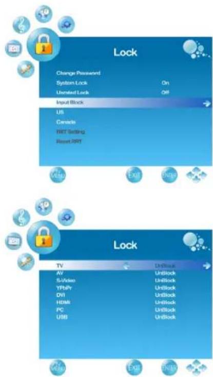
- Press ▲ or ▼ to select "Input Block".
- Press ▲ or ▼ to select the input source, then ◀ or ▶ to select from "Block" or "UnBlock".
- Press MENU to exit.
To Restore Factory Setting
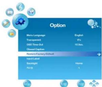
- Press the MENU button to display the OSD main menu.
- Press ◀ or ▶ to select the "OPTION" menu.
- Press ENTER or ▼ to enter "OPTION" menu.
- Press ▲ or ▼ to select "Restore Default", then press ▶ to restore the factory default setting.
- Select "Yes" and press ENTER to confirm the setting.
Setting RS232 Parameter
- Press the MENU button to display the OSD main menu.
- Press ▲ or ▼ to select the "OPTION" menu.
- Press ENTER or ▶ to enter "OPTION" menu.
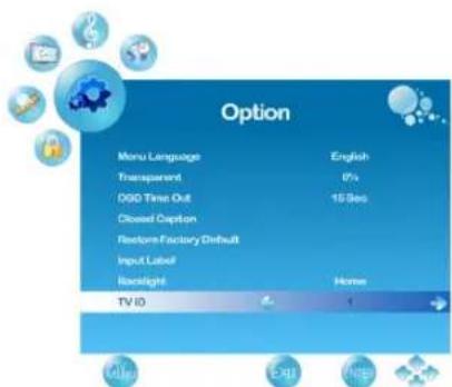
- Press ▲ or ▼ to select "TV ID", then press ◀ or ▶ to set the TV ID number from 01\~98. For detailed information, refer to the RS232 Protocol on page 35\~45.
Using PC Function
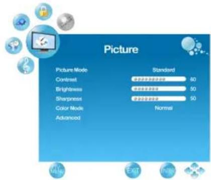
- When in PC source, press the MENU button to display the OSD main menu.
- Press ◀ or ▶ to select the "PICTURE" menu, then press ENTER or ▼ to enter the menu.
- Press ▲ or ▼ to select your desired controls, and press ◀ or ▶ to adjust.
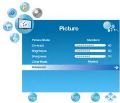
- For advanced PC functions, select "Advanced" (only in PC source) and press ▶ to enter.
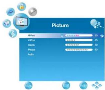
- Press ▲ or ▼ to select "H-Pos" (H-Position), "V-Pos" (V-Position), "Clock", "Phase" or "Auto" (Auto adjustment), and adjust the level with ◀ or ▶.
* When in PC source, the other menus are the same as or similar to when in other source.
* When there is no signal in the PC mode, “No Signal” will be displayed on the screen and the TV will automatically turn into power-saving mode after a few seconds’ idleness. Press INPUT or POWER button on the remote control and the TV will return to VGA mode.
Using USB Function
When input source is selected to USB, insert the USB device into the USB jack. USB only supports JPEG and MP3 files.
Viewing Photo or Silde Show
- Use ◀ or ▶ to select “Photo”.
- Use ▲ or ▼ to select the folder you want, and press ENTER (See Figure1).
- Return to main menu, press ▲ or ▼ to "--" and press ENTER (See Figure 2). Use ▲ or ▼ to select the image files (With ♥ symbol) you want, and press ENTER to play. (See Figure 3 and Figure 4).
In Photo function, you can use the buttons to make following functions:
Press INFO can view all of the functions (See Figure 5)
* Press EXIT go back to the previous page.
* Use ◀ or ▶ to display the next or previous picture.
* Use ▲ or ▼ to rotate right or rotate left the picture.
(Only available in X1.0 mode)
* Press Aspect to zoom in. (X1.5\~X4.0)
* When the Aspect Ratio, press ▲▼◀▶ to move.
* Press ENTER to auto-play or stop the pictures.
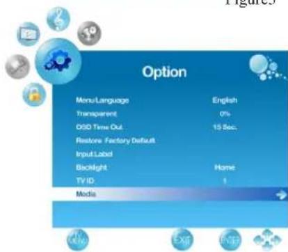
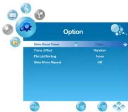
In "Option" menu can setup following functions:
- Press the MENU button to display the OSD main menu.
- Press ◀ or ▶ to select "Option" menu, then press ENTER or ▼ to enter the menu. Press ▲ or ▼ to select "Media", and use ▶ to enter "Media" setting.
•Slide Show Timer:
To select the pictures auto-play interval time.
•Trans. Effect:
To select the auto-play effects of the slide show.
-File List Sorting:
To select the pictures arrange.
•Slide Show Repeat:
To select the slide show repeat to On or Off.
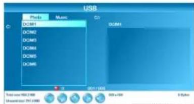
Figure1
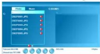
Figure2
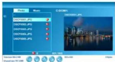
Figure3

natural_image
City skyline at dusk with illuminated skyscrapers reflected in water, no visible text or symbolsFigure4
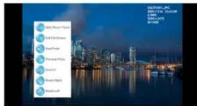
Figure5
Playing the Music
- Use ◀ or ▶ to select "Music".
- Use ▲ or ▼ to select the folder you want, and press ENTER (See Figure1).
- Return to main menu, press ▲ or ▼ to --" and press ENTER (See Figure 2). Use ▲ or ▼ to select the MP3 files (With ♥ symbol) you want, and press ENTER to play. (See Figure 3 and Figure 4).
- In Music function, press ▼ to use all of the functions to control (See Figure 4).
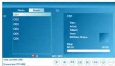
Figure1
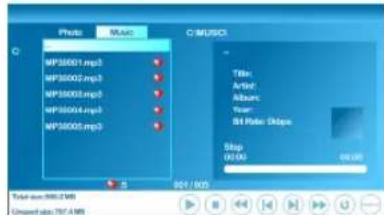
Figure2
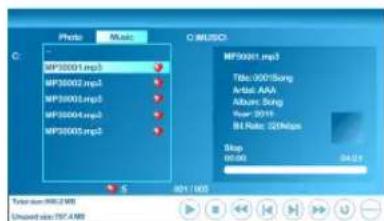
Figure3
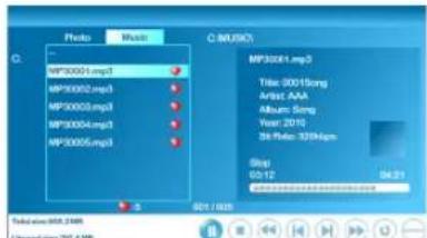
Figure4
Adjusting the Settings
- Press the MENU button to display the OSD main menu. There are six top menus on the screen: PICTURE, AUDIO, TIME, OPTION, LOCK, and CHANNEL. (CHANNEL menu can only be enabled in TV source.)
- Press ◀ or ▶ to select your desired top menu.
- Press ENTER or ▼ to enter the menu you select.
- Use ▲▼ to select the control you want to adjust.
- When selecting the control with ▶, press ▶ to enter next level menu or enable the function. (▶ will only appear when the control is highlighted)
- Press ◀▶ to adjust or select the settings.
- Press MENU to exit from the OSD menu.
Picture menu

Function Description
Picture Mode To select picture mode.
Contrast To adjust contrast of video.
Brightness To adjust luminance of video.
Sharpness To adjust picture sharpness.
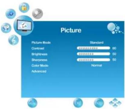
Tint To adjust tint level.(Except PC source)
Color To adjust color.(Except PC source)
Color Mode To select and adjust color mode.
Aspect Ratio To select image size between Normal, Movie Scale, Zoom in and 4:3.(Except PC and USB source)
Noise To reduce the noise level of connected equipment. Reduction (Except PC and USB source)
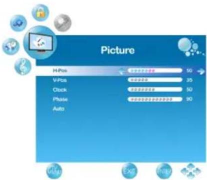
Advanced
To fine tune the image.(Only enabled in PC source)
* H-Pos: To adjust the horizontal position of the picture.
* V-Pos: To adjust the vertical position of the picture.
* Clock: To adjust delay time of clock in order to reduce the noise of picture.
* Phase: To adjust delay time of phase in order to reduce the noise of picture.
* Auto: To auto adjust picture's horizontal position, vertical position, clock, phase, fine tune and H-Size.
Audio menu
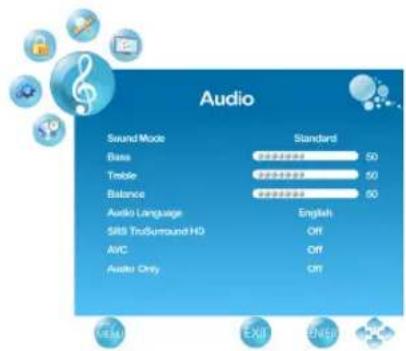
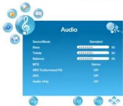
Function Description
Sound Mode To select Sound modes
Bass To adjust bass.
Treble To adjust the treble.
Balance To adjust left and right audio balance.
Audio To select available audio language.
Language (Only available in DTV)
SRS
TruSurround To select "SRS TruSurround HD" effect or not. HD
AVC To turn on/off AVC (automatic volume control) function.
Audio Only To turn off the screen picture but keep the sound on.(Except USB source)
MTS To select audio mode.(EX: Mono, Stereo, SAP) (Only available in ATV)
Time menu (Except USB source)
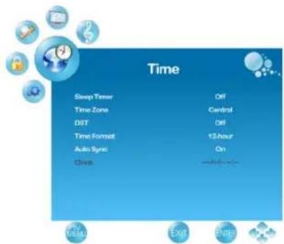
Function Description
Sleep Timer To set the off timer.
Time Zone To select the time zone appropriate to your location.
DST To turn on/off daylight saving.
Time Format To select 12-hour or 24-hour.
Auto Sync To turn on/off Auto Sync.
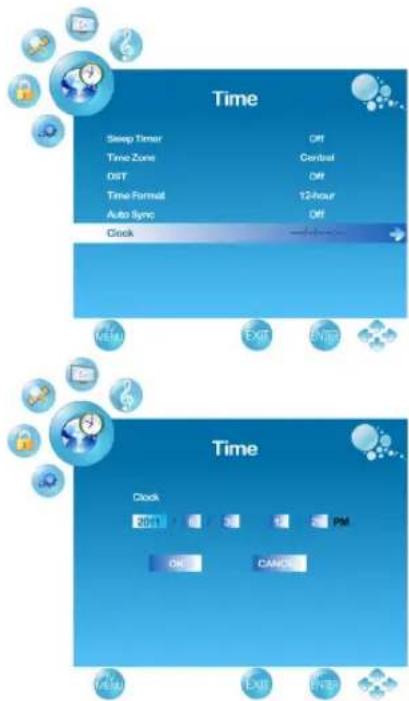
Clock To set the clock.
Use ◀ or ▶ to change between year/ month/ date
/ hour/ minute, ▲ or ▼ to adjust.
When you finish adjustment, select "OK" and press ENTER to complete the setting.
* The “Clock” time can only be adjusted manually when “Auto Sync” is set to “Off”
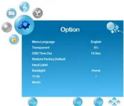
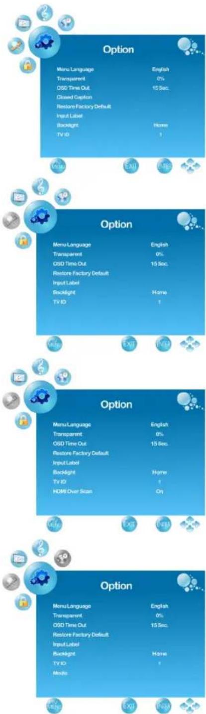
Option menu
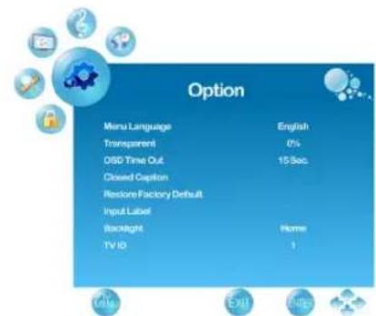
Function Description
Menu Language To select OSD language.
Transparent
To select OSD (On Screen Display) transparent level.
OSD Time Out To select OSD show time.
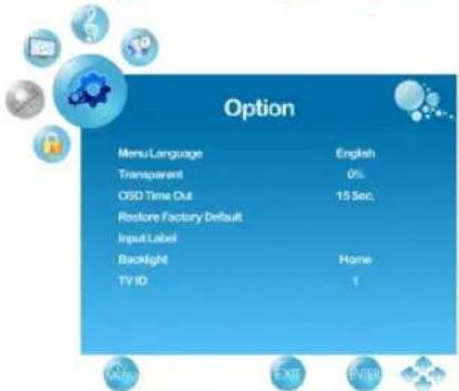
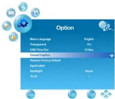
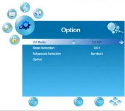
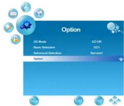
Closed Caption
To set close caption options.
(Only available in TV, AV, S-Video source)
Basic Selection:
To set basic analog closed caption options.
(CC1\~CC4, TEXT1\~TEXT4, Off)
Advanced Selection:
To select closed caption signal formats and set up caption modes for digital TV channels.
(Service1\~6, Off)
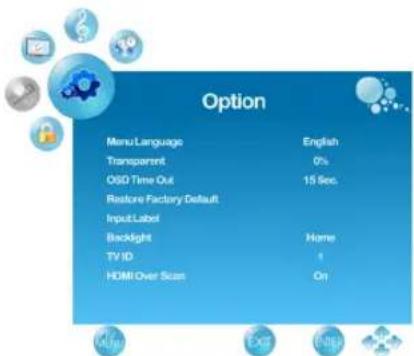
Option menu
Function Description
For detailed Close Caption setting:
Press ◀ or ▶ to select the Mode to be “Custom”, and then use ▲ or ▼ to select desired options and use ◀ or ▶ to adjust detailed settings.
* When you select the Mode to be "Default", you can not adjust the detailed settings.
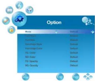
Restore Factory Default To restore the factory default settings.
Input Label To Change the input source name.
Backlight To select backlight brightness between Home, Medium, Low, and High.
TV ID Setting RS232 Parameter.
| HDMI Over Scan | To select this function to On or Off in HDMI. (Only available when input signal is in video timing. Ex:480i, 480p, 720p, 1080i, 1080p) |
| Media | To set the picture slide show setting.(Only available in USB source) |
Lock menu
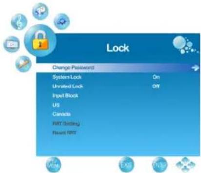
Function Description
Change Password To Change the current Password.
System Lock To select On or Off to Lock parent control.
Unrated Lock To block unrated movie or TV programs.
Input Block To block by input source.
US Select TV and MPAA to set the parent control.
Canada Select Canadian English and Canadian French to set the parent control.
RRT Setting To set Rating Region Table.
Reset RRT To reset Rating Region Table.
Channel menu (Only available in TV source)
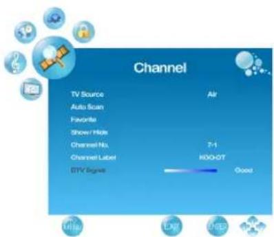
Function Description
TV Source To select TV source. Select "Cable" to watch cable TV channels, and select "Air" to watch air TV channels.
Auto Scan To auto scan ATV and DTV channels.
Favorite To set your favorite channel into memory.
Show/Hide To set the cannel show or hide.
Channel No. To select the cannel you want to edit the name.
Channel Label To edit a name for the current cannel.
DTV Signal To display the detected signal strength of the current DTV channel.
Troubleshooting
Please contact ViewSonic service team directly if you have questions, service needs, or require technical assistance related on the use of your television.
Contact ViewSonic Service Team at:
http://www.ViewSonic.com
Or call our service team:
United States 1-800-688-6688
Canada 1-866-463-4775
Problem Possible Solution
No power • Make sure the power cord is properly connected to the LCD TV AC power socket.
- Make sure the AC power cord is properly connected to the wall outlet.
- Make sure the DC power button is ON (Blue LED).
- Plug another electrical device (like a radio) to the power outlet to verify that the outlet is supplying the proper voltage.
No picture • The TV station may be experiencing problems. Try another channel.
- The Cable TV signal may be scrambled or encoded. Please contact your local cable operator.
- Make sure that connection to other components are correct referring to the user guide.
- Make sure that setup has been done correctly after connections.
- Make sure the correct input is selected and the input signal is compatible.
Strange color, light color, or color misalignment
- Ensure that the video cable is securely connected.
- The picture may appear dim in a brightly lit room.
- Adjust brightness, contrast, saturation (color), and tint referring to the user guide.
- Check the input signal setting.
No sound • Check your audio connections are properly connected referring to the user guide.
- The MUTE button may have been pressed, try pressing this button again.
- Check your audio settings, your TV audio may be set to minimum.
- Press the Volume + (Up) button on the remote control.
Problem Possible Solution
| Remote control unit does not operate | Make sure the directions of batteries are inserted correctly referring to the user guide.Batteries could be weak or dead. Replace with new batteries.Is a fluorescent light illuminated near the remote control sensor?The path of the remote control beam may be blocked. Make sure the path is clear and that the remote control is aimed at the remote control sensor on the TV.Press the POWER button on the remote control to see if you can turn on the TV.Press MENU button on the remote control to see if there is a MENU shown on the screen.Press only one button at a time and it is the correct one for the operation you want to perform. |
| Unit cannot be operated • External influences such as lightning or static electricity may cause improper operation. In this case, operate the unit after first turning on the power of the LCD TV and the AVC System, or unplug the AC cord for 1 to 2 minutes, then replug again. |
Power is cut off suddenly • Is the sleep timer set in advance?
| • Is there no signal in PC mode or HDMI mode? |
| • The internal temperature of the unit has increased. Remove any objects blocking the vent or clean as necessary. |
| No CATV reception (or no reception above CH13) | • Is the AIR/CABLE option set correctly? Please set the AIR/CABLE option to CABLE referring to the user guide.• CATV is connected improperly or not connected; please check all the CATV connections.• The cable TV service is interrupted; please contact your cable operator. |
| Picture is cut off/with sidebar screen | • Is the image positioned correctly? • Are screen mode adjustments such as picture size set correctly? • Press WIDE button repeatedly on the remote control to see if you can get the picture you prefer. |
Specifications
| Model VT2755LED | ||
| LCD(LED Backlight) | Type 27” TFT Active | Matrix RGB0.3114 (H) x 0.3114 (V) mm pixel |
| Color Pixel Arrangement | RGB vertical strip | |
| Surface Treatment AG type, 3H hard coating, Haze 25 | ||
| Input signal | RGB | RGB analog (0.7/1.0 Vp-p, 75 ohms) Separate Sync, f_h : 30-82 kHz, f_v :55-76 HzTV system Antenna / NTSC+ATSC, TV cable system /CATV+Digital cable1 composite RCA, 1 S-Video, 1 YPbPr component, 1 HDMI |
| RF | ||
| Video | ||
| Audio | 1 mini-stereo,2 pair of RCA (L/R) stereo | |
| USB JPEG / MP3 Format | ||
| Compatibility | PC Up to 1920 x 1080 @ 60 Hz, 1 VGA mode, 1 DVI mode | |
| Resolution | Recommended and supported (VGA mode) | 1920 x 1080 @ 60 Hz1680 x 1050 @ 60 Hz1440 x 900 @ 60 Hz1280 x 1024 @ 75 Hz1024 x 768 @ 60, 75 Hz800 x 600 @ 60, 75 Hz640 x 480 @ 60, 75 Hz |
| Speaker Output | 5W x 2 @ THD=10% | |
| Audio Output | 1 Headphone jack, 1 SPDIF (optical) | |
| Power | Voltage 100-240 VAC, 50/60 Hz (auto switch) | |
| Display area | Full Scan 597.89mm (H) x 336.31mm (V)23.54” (H) x 13.24” (V) | |
| Operating conditions | Temperature Humidity Altitude | 32°F to + 104°F (0°C to + 40°C)20% to 80% (no condensation)0 To 6,500 feet (2,000m) |
| Storage condition | Temperature Humidity Altitude | -4°F to + 140°F (-20°C to + 60°C)10% to 90% (no condensation)0 To 12,000 feet (3,790.3m) |
| Dimensions | Physical (W) x (H) x (D) | 646.3mm x 466.2mm x 227.8mm25.44” x 18.35” x 8.97” |
| Weight | Net 5.95 kg (13.12 lb) | |
| Regulations | UL/cUL, FCC-B (Doc-B), NOM, BETS-7, ENERGY STAR®, NRCan, CEC | |
| Power consumption | On Stand by | < 55 W [Max] (blue LED)< 1 W @ 115 Vac only (orange LED) |
| Warning: Do not set the graphics card in your computer to exceed these refresh rates; doing so may result in permanent damage to the LCD TV. | ||
Note: Product Specifications are subject to change without notice.
RS232 Protocol
1. Introduction
This document describes the hardware interface spec and software protocols of RS232 interface communication between Viewsonic Commercial Display and PC or other control unit with RS232 protocol.
The protocol divide into three sections:
- Set-Function
- Get-Function
- Remote control pass-through mode
※In below document, “PC” will represent all the control units that can sent or receive the RS232 protocol command.
2. Description
2.1 Hardware specification
Viewsonic LCD communication port in the rear side
(1) Connector type: DSUB 9 Pin Male
(2) Pin Assignment
Male DSUB 9Pin (outside view)
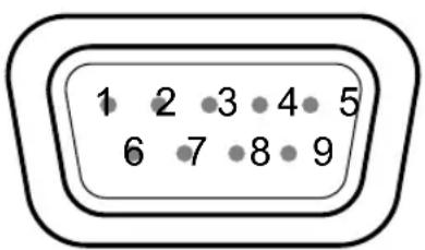
| Pin # Signal | Remark | |
| 1 NC | ||
| 2 RXD Input to LCD Monitor | ||
| 3 TXD Output from LCD Monitor | ||
| 4 NC | ||
| 5 GND | ||
| 6 NC | ||
| 7 NC | ||
| 8 NC | ||
| 9 NC | ||
| frame GND | ||
* Use of crossover (null modem) cable required for use with PC.
2.2 Communication Setting
• Baud Rate Select: 9600bps (fixed)
• Data bits: 8bits (fixed)
- Parity: None (fixed)
- Stop Bits: 1 (fixed)
2.3 Command Message Reference
PC sends to Monitor command packet followed by "CR". Every time PC sends control command to the Monitor, the Monitor shall response as follows:
- If the message is receives correctly it will send “+” (02Bh) followed by “CR” (00Dh)
- If the message is receives incorrectly it will send “-” (02Dh) followed by “CR” (00Dh)
3. Command Description
| Length Total Byte of TV ID Identification | Message excluding “CR” |
| Command Type Identify command type,“s” (0x73h) : Set Command“g” (0x67h) : Get Command“r” (0x72h) : Reply Command“p” (0x70h) : RCU Pass-through“+” (0x2Bh) : Valid command Reply“-” (0x2Dh) : Invalid command Reply | |
| Command Function command code: One byte ASCII code | |
| Value[1~3] Three bytes ASCII that defines the value | |
| CR 0x0D | |
4. Set-Function Listing
The PC can control the LCD Monitor for specific actions. The Set-Function command allows you to control the LCD monitor behavior in a remote sit through the RS232 port. The Set-Function packet format consists of 9 bytes.
Set-Function description:
| Length Total Byte of | Message excluding “CR” |
| TV ID | Identification for each of TV. The TV ID doesn’t be supported by HDTV “power on” command.If we want to set all TV settings, TV ID can use “99” to achieve, and it will not have Reply command on this function.The TV ID can be set via the OSD menu for each TV set. |
| Command Type | Identify command type,“s” (0x73h) : Set Command“+” (0x2Bh) : Valid command Reply“-” (0x2Dh) : Invalid command Reply |
| Command Function | command code: One byte ASCII code |
| Value[1~3] Three bytes ASCII that defines the value | |
| CR 0x0D | |
Set-Function format:
Send (Command Type="s")
[NOTE] Set “Power on” command is the exception.
(Command Type="s", Only for HDTV power on)
Reply (Command Type="+" or "-"
[NOTE] The reply for “Power on” command is the exception. It’s 0x322B0D (2+
(Command Type="+" or "-", Only for HDTV power on)
Example1: Set HDTV power on and this command is valid. Send (Hex Format)
| Name Length | Command Type | Command Value1 | Value2 Value3 | CR | |||
| Hex | 0x36 | 0x73 | 0x21 | 0x30 | 0x30 | 0x31 | 0x0D |
Reply (Hex Format)
| Name | Length Command Type | CR |
| Hex 0x32 | 0x2B | 0x0D |
Example2: Set Brightness as 76 for TV-02 and this command is valid. Send (Hex Format)
| Name Length | ID | Command Type | Command | Value1 | Value2 | Value3 | CR | |
| Hex | 0x38 | 0x300x32 | 0x73 | 0x24 | 0x30 | 0x37 | 0x36 | 0x0D |
Reply (Hex Format)
| Name Length | ID Command | Type | CR | |
| Hex 0x34 | 0x30 | 0x32 | 0x2B | 0x0D |
Example3: Set Brightness as 76 for TV-02 and this command is NOT valid. Send (Hex Format)
| Name Length ID Command | Type | Command Value1 Value2 Value3 CR | |||||||
| Hex 0x38 | 0x30____ | ____0x32 | 0x73 0x | D4 0x30 0x | x37 0x36 0x | 0x0D____ | ____ | ____ | |
Reply (Hex Format)
| Name Length ID Command | Type | CR | ||
| Hex 0x34 | 0x30____ | ____0x32 | 0x2D | 0x0D____ |
Example4: Set Tint as 32 for TV-03 and this command is valid. Send (Hex Format)
| Name | Length | ID Command Type | Command Value1 | Value2 | Value3 CR | |||
| Hex 0x38 | — | 0x30 0x33 | 0x73 0x | 27 — | 0x30 0x | 33 — | 0x32 | 0x0D |
Reply (Hex Format)
| Name | Length | ID Command Type | CR |
| Hex | 0x34 | 0x300x33 | 0x2B0x0D |
Example5: Set Tint as 75 for TV-03 and this command is NOT valid. Send (Hex Format)
| Name Length | ID | Command Type | Command | Value1 | Value2 | Value3 | CR | |
| Hex | 0x38 0x30 __0x33 | 30 | 0x73 | 0xD7 0x30 __ | 30 | 0x37 0x35 __ | 35 __ | 0x0D |
Reply (Hex Format)
| Name Length ID Command | Type | CR | ||
| Hex 0x34 0x30____ | ____0x33 | 0x2D 0x0D____ | ||
Example6: Set Brightness as 76 for all TV and this command is valid. Send (Hex Format)
| Name Length | ID Command | Type | Command | Value1 | Value2 | Value3 | CR | ||
| Hex 0x38 | 0x39____ | ____0x39 | 0x73 0x | 24 0x30 0x | 37 0x36 | 0x0D____ | ____ | ____ | |
No Reply..
Table 4-1: PC Set-function command to LCD Monitor (ID=C0h)
| Set Function | Length | ID | Command Type (ASCII) | Command Code (ASCII) | Command Code (Hex) | Value Range (Three ASCII bytes) | Comments |
| HDTV Power off/standby | 8 s ! | 21 000 | STBY | ||||
| Power on 6 n/a | s ! 21 001: ON | ||||||
| Input Select s | 22 | 000: TV001: AV002: SV003: YPBPR004: DVI005: HDMI006: VGA | 1. No need for USB2. Extend the value for more inputs | ||||
| Contrast | 8 | s | # | 23 | 000 ~ 100 | ||
| Brightness | 8 | s | $ | 24 | 000 ~ 100 | ||
| Sharpness | 8 | s | % | 25 | 000 ~ 100 | ||
| Color | 8 | s | & | 26 | 000 ~ 100 | ||
| Tint | 8 s | 27 000 ~ 100 | |||||
| Color Mode | 8 s ) | 29 | 000: NORMAL001: WARM002: COLD003: Personal | ||||
| Surround | 8 | s | - | 2D | 000: SRS OFF001: SRS ON | ||
| Bass | 8 | s | . | 2E | 000 ~ 100 | Sets Bass value | |
| Treble | 8 | s | / | 2F | 000 ~ 100 | Sets Treble value | |
| Balance | 8 | s | 0 | 30 | 000 ~ 100 | Sets Balance position | |
| OSD Language | 8 s | 2 | 32 | 000: English001: French002: Spanish | Extend the value for more supported languages | ||
| Power Lock | 8 | s | 4 | 34 | 000: Unlock001: Lock | ||
| Volume | 8 | s | 5 | 35 | 000 ~ 100 | ||
| Mute 8 s | 6 | 36 | 000: OFF001: ON (mute) | ||||
| Button Lock | 8 | s | 8 | 38 | 000 : Unlock001 : Lock | ||
| TV Channel | 8 | s | = | 3D | 000 ~ 999 | ||
| Menu Lock | 8 | s | > | 3E | 000: Unlock001: Lock | ||
| Number | 8 | s | @ | 40 | 000 ~ 009 | ||
| Key Pad | 8 | A | 41 000: UP001: DOWN002: LEFT003: RIGHT004: ENTER005: INPUT006: MENU/EXIT | ||||
| Remote Control | 8 s | B 42 | 000: DISABLE001: ENABLE002: PASS THROUGH | Disable: RCU has no effect on HDTV.Enabled: RCU controls the HDTV.This is the power up default on the HDTV.Pass through: RCU has no effect on HDTV and all RCU command codes are transmitted to FC via the RS232 port. See page 44 for more details | |||
| Setup wizard | 8 s C | 43 | 000: Disable001: Enable | Disable: to skip the initial setup wizard | |||
| Restore To Default | s | ~ | 7E | 000 | Rests HDTV to factory setting | ||
5. Get-Function Listing
The PC can interrogate the LCD Monitor for specific information. The Get-Function packet format consists of 9 bytes which is similar to the Set-Function packet structure. Note that the "Value" byte is always = 00.
Get-Function description:
| Length Total Byte of | Message excluding “CR” |
| TV ID Identification | for each of TV. The TV ID doesn’t be supported by HDTV power status on standby. |
| Command Type | Identify command type,“g” (0x67h) : Get Command“r” (0x72h) : Valid command Reply“-” (0x2Dh) : Invalid command Reply |
| Command Function | command code: One byte ASCII code |
| Value[1~3] Three bytes ASCII that defines the value | |
| CR 0x0D | |
Get-Function format:
Send (Command Type="g")
[NOTE] Get “Power STBY status” is the exception.
(Command Type="g", Only for HDTV power status on standby)
Reply: (Command Type="r" or "-"
If the Command is valid, Command Type = "r"
[NOTE] The reply for “Power STBY status” command is the exception.
It's 0x36 72 6C 30 30 30 0D (6rl000
If the Command is valid, Command Type = "r", Only for HDTV power status on standby.
If the Command is Not valid, Command Type="-"
If the Command is Not valid, Command Type= “-”, Only for HDTV power status on standby.
Example1: Get power status on standby and this command is valid. Send (Hex Format)
| Name Length | Command | Type | Command | Value1 | Value2 | Value3 | CR | |
| Hex 0x36 0x67 | 0x6C 0x30 | 0x30 0x30 | 0x0D | — | — | — | — | — |
Reply (Hex Format)
| Name Length | Command Type | Command | Value1 | Value2 Value3 | CR | |
| Hex 0x36 0x | 72 0x6C 0x30 | 0x30 0x30 | 0x0D | — | — | — |
Example2: Get Brightness from TV-05 and this command is valid. The Brightness value is 67.
Send (Hex Format)
| Name | Length | ID | Command Type | Command | Value1 | Value2 | Value3 CR |
| Hcx | 0x38 0x30 | 0x35 | 0x67 0x62 | _ | 0x30 | 0x30 0x30 | _ |
Reply (Hex Format)
| Name | Length | ID | Command Type | Command Value1 | Value2 Value3 | CR | ||
| Hex 0x38 | — | 0x300x35 | 0x72 0x6 | 2 | — | 0x30 0x36 | — | 0x37 |
Example3: Get Brightness from TV-05, but the Brightness command ID is error and it is NOT in the command table. Send (Hex Format)
| Name Length | ID | Command Type | Command Value1 Value2 Value3 CR | ||
| Hex 0x38 0x30 | ____ | 0x67 0xD3 ____ 0x30 0x30 0x30 | 0x0D ____ | ____ | ____ |
Reply (Hex Format)
| Name Length | ID | Command | Type | CR |
| Hex 0x34 0x30 | _ | _0x35 | 0x2D | 0x0D |
Example4: Get Tint from TV-07 and this command is valid.
The Tint value is +32.
Send (Hex Format)
| Name Length | ID Command | Type | Command | Value1 | Value2 | Value3 | CR | |
| Hex 0x38 | 0x30____ | ____0x37 | 0x67 0x | 65 0x30 | 0x30 | 0x30 0x | 0D____ | ____ |
Reply (Hex Format)
| Name Length | ID Command | Type | Command | Value1 | Value2 | Value3 | CR | |
| Hex 0x38 | 0x30____ | 0x37 0x72 0x | 65 0x2B | 0x33 | 0x32 | 0x0D____ | ____ | ____ |
Example5: Get Tint from TV-07, but the Tint command ID is error and it is NOT in the command table.
Send (Hex Format)
| Name Length | ID Command | Type | Command | Value1 | Value2 | Value3 | CR | |
| Hex 0x38 | 0x30____ | 0x37 | 0x67 | 0xD7 | 0x30 | 0x30 | 0xD____ | ____ |
Reply (Hex Format)
| Name Length ID Command | Type | CR | ||
| Hex 0x34 | 0x30____ | ____0x37 | 0x2D 0x | 0D____ |
§ Table 5-1 outlines the Get-function command list that must be supported by the LCD Monitor.
Table 5-1: PC Get-function command to LCD Monitor
| Get Function Length ID | Command Type | Command Code (ASCII) | Command Code (Hex) | Response Range (Three ASCII bytes) | Comments |
| Get-Contrast | 8 | g | a | 61 | 000 ~ 100 |
| Get-Brightness g b 62 00 ~ 100 Gets Brightness value | |||||
| Get-Sharpness 8 g c 63 00 ~ 100 Gets Sharpness value | |||||
| Get-Color | 8 | g | d | 64 | 000 ~ 100 |
| Get-Tint | 8 g c | 65 000 ~ 100 Gets Tint value | |||
| Get-Volume | 8 | g | f | 66 | 000 ~ 100 |
| Get-Mute | 8 g g | 67 | 000: OFF (unmuted)001: ON (muted) | ||
| Get-Input select | 8 | g | j | 6A | 000: TV001: AV002: SV003: YPBPR004: DVI005: HDMI006: VGA |
| Get-Power status:STBY | 6 | n/a | g | 1 | 6C |
| Get-Power status:ON | 8 g | 16C | 001 | ||
| Get-Remote Control | 8 | g n | 6E | 000: DISABLE001: ENABLE002: PASS THROUGH | |
| Get-Power Lock | 8 g o | 6F | 000: Unlock001: Lock | ||
| Get-Button Lock | 8 g p | 70 | 000: Unlock001: Lock | ||
| Get-Menu Lock | 8 g q | 71 | 000: Unlock001: Lock | ||
| Get-Setup wizard | 8 g s | 73 | 000: Disable001: Enable | ||
| Get-ACK | 8 | g | z | 7A | 000 |
6. Remote Control Pass-through mode
When PC sets the LCD monitor to Remote Control Pass through mode, the LCD shall send a three bytes packet (followed by “CR”) in response to RCU button activation. Note, that in this mode the RCU shall have no effect on the monitor function. For example: “+Volume” will not change the volume in the LCD but only sends “+Volume” code to PC over the RS232 port.
RCU Pass-through Command description:
| Length Total Byte of | Message excluding “CR” |
| TV ID Identification for each of TV | |
| Command Type Identify command type,“p” (0x70h) : RCU Pass-through | |
| Value[1~2] Two bytes ASCII that defines the value | |
| CR 0x0D | |
RCU Pass-through Command Format:
Reply: (Command Type="p")
Example1: User press "Menu" Key form RCU to TV-03 and RCU data pass-through to Server, then server will receive "1A".
Reply (Hex Format)
| Name Length | ID Command | Type | Value1 | Value2 CR | ||
| Hex | 0x36 | 0x300x33 | 0x70 | 0x31 | 0x41 | 0x0D |
Example2: User press "5" Key form RCU to TV-07 and RCU data pass-through to Server, then server will receive "05".
Reply (Hex Format)
| Name Length | ID Command | Type | Value1 | Value2 CR | ||
| Hex | 0x36 | 0x300x37 | 0x70 | 0x30 | 0x35 | 0x0D |
Table 6-1: Baseline RCU Pass-through codes
| Key Code (HEX) Key Code (HEX) | |||
| 1 01 31 | |||
| 2 02 32 | |||
| 3 03 33 | |||
| 4 04 34 | |||
| 5 05 35 | |||
| 6 06 36 | |||
| 7 07 37 | |||
| 8 08 38 | |||
| 9 09 39 | |||
| 0 0A 3A | |||
| - 0B 3B | |||
| RECALL 0C 3C | |||
| 0D 3D | |||
| 0E 3E | |||
| ASPECT 0F 3F | |||
| VOLUME UP (+) ▲ 10 40 | |||
| VOLUME DOWN (-) ▼ 11 | 41 | ||
| MUTE | 12 42 | ||
| CHANNEL/PAGE UP (+) ▲ | 13 | 43 | |
| CHANNEL/PAGE DOWN (-) ▼ | 14 | 44 | |
| POWER | 15 45 | ||
| SOURCES (INPUTS) | 16 46 | ||
| 17 47 | |||
| 18 48 | |||
| SLEEP | 19 49 | ||
| MENU | 1A 4A | ||
| UP ▲ | 1B 4B | ||
| DOWN ▼ | 1C 4C | ||
| LEFT ◀ | 1D 4D | ||
| RIGHT ▶ | 1E 4E | ||
| OK (ENTER) | 1F 4F | ||
| EXIT | 20 50 | ||
| 21 51 | |||
| 22 52 | |||
| 23 53 | |||
| 24 54 | |||
| 25 55 | |||
| 26 56 | |||
| 27 57 | |||
| 28 58 | |||
| 29 59 | |||
| 2A 5A | |||
| 2B 5B | |||
| 2C 5C | |||
| 2D 5D | |||
| 2E 5E | |||
| 2F 5F |
Customer Support
For technical support or product service, see the table below or contact your reseller.
Note: You will need the product serial number.
Use with other Wall-Mount kit may cause instability and possibly result in injury.
To find the perfect mount for VT2755LED, please browse www.viewsonic.com or call our service team: United States 1-800-688-6688, Canada 1-866-463-4775.
| Country/Region Website | T = TelephoneF = FAX | ||
| United States www.viewsonic.com | T (Toll-Free)= 1-800-688-6688T (Toll)= 1-424-233-2530F= 1-909-468-3757 | service.us@viewsonic.com | |
| Canada www.viewsonic.com | T (Toll-Free)= 1-866-463-4775T (Toll)= 1-424-233-2533F= 1-909-468-3757 | service.ca@viewsonic.com | |
| Latin America(Argentina) | www.viewsonic.com/la/ T= 0800-4441185 soporte@viewsonic.com | ||
| Latin America (Chile) www.viewsonic.com/la/ T= 1230-020-7975 soporte@viewsonic.com | |||
| Latin America(Columbia) | www.viewsonic.com/la/ T= 01800-9-157235 soporte@viewsonic.com | ||
| Latin America (Mexico) www.viewsonic.com/la/ T= 001-8882328722 soporte@viewsonic.com | |||
| Renta y Datos, 29 SUR 721, COL. LA PAZ, 72160 PUEBLA, PUE. Tel: 01.222.891.55.77 CON 10 LINEASElectroser, Av Reforma No. 403Gx39 y 41, 97000 Mérida, Yucatán. Tel: 01.999.925.19.16Other places please refer to http://www.viewsonic.com/la/soporte/index.htm#Mexico | |||
| Latin America (Peru) | www.viewsonic.com/la/ | T= 0800-54565 | soporte@viewsonic.com |
Limited Warranty
VIEWSONIC LED TV
What the warranty covers:
ViewSonic warrants its products to be free from defects in material and workmanship, under normal use, during the warranty period. If a product proves to be defective in material or workmanship during the warranty period, ViewSonic will, at its sole option, repair or replace the product with a like product. Replacement product or parts may include remanufactured or refurbished parts or components.
How long the warranty is effective:
ViewSonic LED TVs are warranted for 3 years for all parts excluding the light source and 3 years for labor from the date of the first customer purchase.
Who the warranty protects:
This warranty is valid only for the first consumer purchaser.
What the warranty does not cover:
-
Any product on which the serial number has been defaced, modified or removed.
-
Damage, deterioration or malfunction resulting from:
a. Accident, misuse, neglect, fire, water, lightning, or other acts of nature, unauthorized product modification, or failure to follow instructions supplied with the product.
b. Repair or attempted repair by anyone not authorized by ViewSonic.
c. Any damage of the product due to shipment.
d. Removal or installation of the product.
c. Causes external to the product, such as electric power fluctuations or failure.
f. Use of supplies or parts not meeting ViewSonic's specifications.
g. Normal wear and tear.
h. Any other cause which does not relate to a product defect.
-
Any product exhibiting a condition commonly known as “image burn-in” which results when a static image is displayed on the product for an extended period of time.
-
Removal, installation, and set-up service charges.
- When you mount it on the wall, the following must be noticed:
a. The accessories attached with this product are applicable for this product only.
b. When the product is mounted on the wall, holes and fixed screws will remain in the wall body.
c. Wall face may discolor when this product has been mounted on the wall for a long time.
How to get service:
- For information about receiving service under warranty, contact ViewSonic Customer Support (please refer to Customer Support page). You will need to provide your product's serial number.
- To obtain warranted service, you will be required to provide (a) the original dated sales slip, (b) your name, (c) your address, (d) a description of the problem, and (e) the serial number of the product.
- Take or ship the product freight prepaid in the original container to an authorized ViewSonic service center or ViewSonic.
- For additional information or the name of the nearest ViewSonic service center, contact ViewSonic.
Limitation of implied warranties:
There are no warranties, express or implied, which extend beyond the description contained herein including the implied warranty of merchantability and fitness for a particular purpose.
Exclusion of damages:
ViewSonic's liability is limited to the cost of repair or replacement of the product. ViewSonic shall not be liable for:
- Damage to other property caused by any defects in the product, damages based upon inconvenience, loss of use of the product, loss of time, loss of profits, loss of business opportunity, loss of goodwill, interference with business relationships, or other commercial loss, even if advised of the possibility of such damages.
- Any other damages, whether incidental, consequential or otherwise.
- Any claim against the customer by any other party.
Effect of state law:
This warranty gives you specific legal rights, and you may also have other rights which vary from state to state. Some states do not allow limitations on implied warranties and/or do not allow the exclusion of incidental or consequential damages, so the above limitations and exclusions may not apply to you.
Sales outside the U.S.A. and Canada:
For warranty information and service on ViewSonic products sold outside of the U.S.A. and Canada, contact ViewSonic or your local ViewSonic dealer.
The warranty period for this product in mainland China (Hong Kong, Macao and Taiwan Excluded) is subject to the terms and conditions of the Maintenance Guarantee Card.
For users in Europe and Russia, full details of warranty provided can be found in www.viewsoniccurope.com under Support/Warranty Information.
4.3: ViewSonic LED TV Warranty
LTV_LW01 Rev. 1C 06-25-07
Mexico Limited Warranty VIEWSONIC LED TV
What the warranty covers:
ViewSonic warrants its products to be free from defects in material and workmanship, under normal use, during the warranty period. If a product proves to be defective in material or workmanship during the warranty period, ViewSonic will, at its sole option, repair or replace the product with a like product. Replacement product or parts may include remanufactured or refurbished parts or components & accessories.
How long the warranty is effective:
ViewSonic LED TVs are warranted for 3 years for all parts excluding the light source and 3 years for labor from the date of the first customer purchase.
Who the warranty protects:
This warranty is valid only for the first consumer purchaser.
What the warranty does not cover:
- Any product on which the serial number has been defaced, modified or removed.
- Damage, deterioration or malfunction resulting from:
a. Accident, misuse, neglect, fire, water, lightning, or other acts of nature, unauthorized product modification, unauthorized attempted repair, or failure to follow instructions supplied with the product.
b. Any damage of the product due to shipment.
c. Causes external to the product, such as electrical power fluctuations or failure.
d. Use of supplies or parts not meeting ViewSonic's specifications.
e. Normal wear and tear.
f. Any other cause which does not relate to a product defect. - Any product exhibiting a condition commonly known as “image burn-in” which results when a static image is displayed on the product for an extended period of time.
- Removal, installation, insurance, and set-up service charges.
How to get service:
For information about receiving service under warranty, contact ViewSonic Customer Support (Please refer to the attached Customer Support page). You will need to provide your product's serial number, so please record the product information in the space provided below on your purchase for your future use. Please retain your receipt of proof of purchase to support your warranty claim.
For Your Records
Product Name: ____ Model Number: ____
Document Number: Serial Number:
Purchase Date: ____ Extended Warranty Purchase? ____(Y/N)
If so, what date does warranty expire?
- To obtain warranty service, you will be required to provide (a) the original dated sales slip, (b) your name, (c) your address, (d) a description of the problem, and (e) the serial number of the product.
- Take or ship the product in the original container packaging to an authorized ViewSonic service center.
- Round trip transportation costs for in-warranty products will be paid by ViewSonic.
Limitation of implied warranties:
There are no warranties, express or implied, which extend beyond the description contained herein including the implied warranty of merchantability and fitness for a particular purpose.
Exclusion of damages:
ViewSonic's liability is limited to the cost of repair or replacement of the product. ViewSonic shall not be liable for:
- Damage to other property caused by any defects in the product, damages based upon inconvenience, loss of use of the product, loss of time, loss of profits, loss of business opportunity, loss of goodwill, interference with business relationships, or other commercial loss, even if advised of the possibility of such damages.
- Any other damages, whether incidental, consequential or otherwise.
- Any claim against the customer by any other party.
- Repair or attempted repair by anyone not authorized by ViewSonic.
| Contact Information for Sales & Authorized Service (Centro Autorizado de Servicio) within Mexico: | |
| Name, address, of manufacturer and importers:México, Av. de la Palma #8 Piso 2 Despacho 203, Corporativo Interpalmas,Col. San Fernando Huixquilucan, Estado de MéxicoTel: (55) 3605-1099http://www.viewsonic.com/la/soporte/index.htm | |
| NÚMERO GRATIS DE ASISTENCIA TÉCNICA PARA TODO MÉXICO: 001.866.823.2004 | |
| Hermosillo:Distribuciones y Servicios Computacionales SA de CV.Calle Juarez 284 local 2Col. Bugambilas C.P: 83140Tel: 01-66-22-14-9005E-Mail: disc2@hmo.megared.net.mx | Villahermosa:Compumantenimietnos Garantizados, S.A. de C.V.AV. GREGORIO MENDEZ #1504COL, FLORIDA C.P. 86040Tel: 01 (993) 3 52 00 47 / 3522074 / 3 52 20 09E-Mail: compumantenimientos@prodigy.net.mx |
| Puebla, Pue. (Matriz):RENTA Y DATOS, S.A. DE C.V. Domicilio:29 SUR 721 COL. LA PAZ72160 PUEBLA, PUE.Tel: 01(52).222.891.55.77 CON 10 LINEASE-Mail: datos@puebla.megared.net.mx | Veracruz, Ver.:CONEXION Y DESARROLLO, S.A DE C.V. Av.Americas # 419ENTRE PINZÓN Y ALVARADOFracc. Reforma C.P. 91919Tel: 01-22-91-00-31-67E-Mail: gacosta@qplus.com.mx |
| ChihuahuaSoluciones Globales en ComputaciónC. Magisterio # 3321 Col. MagisterialChihuahua, Chih.Tel: 4136954E-Mail: Cefco@soluglobales.com | CuernavacaCompusupport de Cuernavaca SA de CVFrancisco Leyva # 178 Col. Miguel HidalgoC.P. 62040, Cuernavaca MorelosTel: 01 777 3180579 / 01 777 3124014E-Mail: aquevedo@compusupportcva.com |
| Distrito Federal:QPLUS, S.A. de C.V.Av. Coyoacán 931Col. Del Valle 03100, México, D.F.Tel: 01(52)55-50-00-27-35E-Mail : gacosta@qplus.com.mx | Guadalajara, Jal.:SERVICRECE, S.A. de C.V.Av. Niños Héroes # 2281Col. Arcos Sur, Sector Juárez44170, Guadalajara, JaliscoTel: 01(52)33-36-15-15-43E-Mail: mmiranda@servicrece.com |
| Guerrero AcapulcoGS Computación (Grupo Sesicomp)Progreso #6-A, Colo Centro39300 Acapulco, GuerreroTel: 744-48-32627 | Monterrey:Global Product ServicesMar Caribe # 1987, Esquina con Golfo PésicoFracc. Bernardo Reyes, CP 64280Monterrey N.L. MéxicoTel: 8129-5103E-Mail: aydeem@gps1.com.mx |
| MERIDA:ELECTROSERAv Reforma No. 403Gx39 y 41Mérida, Yucatán, México CP97000Tel: (52) 999-925-1916E-Mail: rrrb@sureste.com | Oaxaca, Oax.:CENTRO DE DISTRIBUCION YSERVICIO, S.A. de C.V.Murguía # 708 P.A., Col. Centro, 68000, OaxacaTel: 01(52)95-15-15-22-22Fax: 01(52)95-15-13-67-00E-Mail. gpotai2001@hotmail.com |
| Tijuana:STDAv Ferrocarril Sonora #3780 L-CCol 20 de NoviembreTijuana, Mexico | FOR USA SUPPORT:ViewSonic Corporation381 Brea Canyon Road, Walnut, CA. 91789 USATel: 800-688-6688 (English); 866-323-8056 (Spanish);Fax: 1-800-685-7276E-Mail: http://www.viewsonic.com |
4.3: ViewSonic Mexico Limited Warranty
LTV_LW02 Rev. 1A 06-25-07
- Getting Started
- Using the TV Features
- Other Information
- Compliance Information
- FCC Statement
- Following information is only for EU-member states:
- ENERGY STAR Information:
- SRS Trademark Information:
- Declaration of RoHS Compliance
- Copyright Information
- Product Registration
- For Your Records
- Product disposal at end of product life
- IMPORTANT SAFETY INSTRUCTIONS
- Instruction: The
- USE
- AC power Cord
- Wall outlet
- Wiring
- Electric shock
- Lightning storms
- When not in use
- Overloading
- Optional equipment
- Small accessories
- Magnetic influence
- Sound
- Use in outdoor
- Vehicle, ships and other vessels
- Medical institutions
- Volume adjustment
- ANTENNAS
- Outdoor antenna grounding
- Antenna grounding according to the National
- Electrical Code, ANS/NFPA 70
- CLEANING
- Cleaning the AC power plug
- Cleaning the screen surface/ cabinet of the TV set
- Disclaimer
- CARRYING THE TV
- Carry the TV as instructed
- VENTILATION
- Installed on the wall
- Installed with stand
- ViewSonic
- Objects and ventilation holes
- MOISTURE
- Moisture and flammable objects
- INSTALLATION
- Optional wall mount
- Placement
- Preventing the TV from toppling over
- Placement for watching
- LCD SCREEN
- Broken pieces
- Handling of broken glass and liquid crystal leakage
- SERVICING
- Replacement parts
- Safety check
- Package Contents
- Installing the LCD TV
- Installing the Stand
- Disconnecting the Stand
- Mounting ViewSonic LCD TV to the wall
- Wall Mount Kit Specifications (VESA)
- Front View of the Product
- Rear View of the Product
- Connecting the LCD TV
- Cable System or VHF/UHF Antenna System
- [Non-Text]
- Cable or VHF/UHF
- Cable System and VHF/UHF Antenna System
- HD Cable Box/HD Satellite Box
- HDMI Connection
- DVI Connection
- YPbPr or Component Connection
- Programming your Cable or Satellite Box remote
- SD DVD Player
- Personal Computer
- Remote Control and TV Controls
- Inserting Remote Control Batteries
- CAUTION
- Button Description
- Operation
- Turning the TV On and Off
- Initial Setup
- Changing Channels
- Adjusting the Volume
- Viewing the Displayed Information
- Storing Channels into Memory
- Selecting the Input Source
- Favorite Channel Setting
- Adding/Erasing Channel
- Channel Name Setting
- Using the Parent Controls
- To Block Unrated Movie or TV Programs
- To Set Rating Region Table
- To Change Password
- To block by Input Source
- To Restore Factory Setting
- Setting RS232 Parameter
- Using PC Function
- Using USB Function
- Viewing Photo or Silde Show
- In Photo function, you can use the buttons to make following functions:
- In "Option" menu can setup following functions:
- •Slide Show Timer:
- •Trans. Effect:
- -File List Sorting:
- •Slide Show Repeat:
- Playing the Music
- Adjusting the Settings
- Picture menu
- Function Description
- Advanced
- Audio menu
- SRS
- Time menu (Except USB source)
- Option menu
- Basic Selection:
- Advanced Selection:
- Lock menu
- Channel menu (Only available in TV source)
- Troubleshooting
- Problem Possible Solution
- RS232 Protocol
- Introduction
- Description
- Hardware specification
- Communication Setting
- Command Message Reference
- Command Description
- Set-Function Listing
- Set-Function description:
- Set-Function format:
- Get-Function Listing
- Get-Function format:
- Reply: (Command Type="r" or "-"
- Remote Control Pass-through mode
- RCU Pass-through Command Format:
- Customer Support
- Limited Warranty
- VIEWSONIC LED TV
- What the warranty covers:
- How long the warranty is effective:
- Who the warranty protects:
- What the warranty does not cover:
- How to get service:
- Limitation of implied warranties:
- Exclusion of damages:
- Effect of state law:
- Sales outside the U.S.A. and Canada:
- Mexico Limited Warranty VIEWSONIC LED TV
Brand : VIEWSONIC
Model : VT2755LED
Category : Screen