
CDP4262-L - Screen VIEWSONIC - Free user manual and instructions
Find the device manual for free CDP4262-L VIEWSONIC in PDF.


| Product Type | LCD Commercial Display |
| Screen Size | 42 inches (diagonal) |
| Resolution | 1920 x 1080 (Full HD) |
| Brightness (Typical) | 700 cd/m² |
| Contrast Ratio (Typical) | 1300:1 |
| Viewing Angle | 178° horizontal / 178° vertical |
| Panel Type | LCD with LED backlight |
| Displayable Colors | 1.06 Billion |
| Pixel Pitch | 0.4845 x 0.4845 mm |
| Input Terminals | HDMI, DVI-D, VGA, DisplayPort, Component (BNC) |
| Output Terminals | DVI-I (DVI-D & VGA) output, RS232C out, IR out |
| Audio | Internal speakers 10W+10W, Audio in/out (RCA, 3.5mm) |
| Power Consumption (Max) | 150 W |
| Power Consumption (Standby) | < 0.5 W (with RS232 active) |
| Power Supply | AC 100-240V, 50/60 Hz |
| Dimensions (W x H x D) without Stand | 965.8 x 558.8 x 69 mm |
| Weight without Stand | 18.3 kg |
| VESA Mounting | 400 x 200 mm, 200 x 200 mm (compatible) |
| Operating Temperature | 0°C to 40°C |
| Humidity (Operating) | 20% to 80% RH (non-condensing) |
| Cleaning | Use soft lint-free cloth; mild detergent if needed; avoid solvents |
| Safety Features | Kensington lock, overheat protection, auto power off |
| Included Accessories | Power cord (1.8m), VGA cable (1.8m), RS232 cable (3m), remote control, CD-ROM, Quick Start Guide |
Frequently Asked Questions - CDP4262-L VIEWSONIC
User questions about CDP4262-L VIEWSONIC
0 question about this device. Answer the ones you know or ask your own.
Ask a new question about this device
Download the instructions for your Screen in PDF format for free! Find your manual CDP4262-L - VIEWSONIC and take your electronic device back in hand. On this page are published all the documents necessary for the use of your device. CDP4262-L by VIEWSONIC.
USER MANUAL CDP4262-L VIEWSONIC
IMPORTANT: Please read this User Guide to obtain important information on installing and using your product in a safe manner, as well as registering your product for future service. Warranty information contained in this User Guide will describe your limited coverage from ViewSonic Corporation, which is also found on our web site at http://www.viewsonic.com in English, or in specific languages using the Regional selection box in the upper right corner of our website. "Antes de operar su equipo lea cu idadosamente las instrucciones en este manual"
Model No. VS15673/VS15674/VS15662/VS15663/VS15664
Compliance Information
NOTE: This section addresses all connected requirements and statements regarding regulations. Confirmed corresponding applications shall refer to nameplate labels and relevant markings on unit.
FCC Statement
This device complies with Part 15 of the FCC Rules. Operation is subject to the following two conditions: (1) this device may not cause harmful interference, and (2) this device must accept any interference received, including interference that may cause undesired operation.
NOTE: This equipment has been tested and found to comply with the limits for a Class A/Class B digital device, pursuant to Part 15 of the FCC Rules. These limits are designed to provide reasonable protection against harmful interference when the equipment is operated in a commercial environment. This equipment generates, uses, and can radiate radio frequency energy and, if not installed and used in accordance with the instructions, may cause harmful interference to radio communications. Operation of this equipment in a residential area is likely to cause harmful interference in which case the user will be required to correct the interference at his/her own expense.
- Reorient or relocate the receiving antenna.
- Increase the separation between the equipment and receiver.
- Connect the equipment into an outlet on a circuit different from that to which the receiver is connected.
- Consult the dealer or an experienced radio/TV technician for help.
Warning: To comply with the limits for the Class A/Class B digital device, pursuant to Part 15 of the FCC Rules, this device must be installed in computer equipment certified to comply with the Class A/Class B limits. All cables used to connect the computer and peripherals must be shielded and grounded. Operation with non-certified computers or non-shielded cables may result in interference to radio or television reception. Changes and modifications not expressly approved by the manufacturer could void the user's authority to operate this equipment.
For Canada
CAN ICES-3 (A/B)/NMB-3(A/B)
CE Conformity for European Countries

The device complies with the EMC Directive 2004/108/EC and Low Voltage Directive 2006/95/EC.
Following information is only for EU-member states:
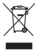
The mark shown to the right is in compliance with the Waste Electrical and Electronic Equipment Directive 2002/96/EC (WEEE).
The mark indicates the requirement NOT to dispose of the equipment as unsorted municipal waste, but use the return and collection systems according to local law.
If the batteries, accumulators and button cells included with this equipment, display the chemical symbol Hg, Cd, or Pb, then it means that the battery has a heavy metal content of more than 0.0005% Mercury or more than, 0.002% Cadmium, or more than 0.004% Lead.
Industry Canada Notice
This device complies with Canadian RSS-210. To prevent radio interference to the licensed service, this device is intended to be operated indoors and away from windows to provide maximum shielding. Equipment (or its transmitting antenna) that is installed outdoors is subject to licensing. The installer of this radio equipment must ensure that the antenna is located or pointed such that it does not emit RF field in excess of Health Canada limits for the general population; consult Safety Code 6, obtainable from Health Canada's website www.hc-sc.gc.ca/rpb.
R&TTE Compliance Statement
This device complies with the Essential Requirements of the R&TTE Directive of the European Union (1999/5/EC). This equipment meets the following conformance standards:
ETSI EN 300 328
EN 301 489-01
EN 301 489-17
EN 62311
Notified Countries: Germany, UK, Netherlands, Belgium, Sweden, Denmark, Finland, France, Italy, Spain, Austria, Ireland, Portugal, Greece, Luxembourg, Estonia, Latvia, Lithuania, Czech Republic, Slovakia, Slovenia, Hungary, Poland and Malta.
Declaration of RoHS2 Compliance
This product has been designed and manufactured in compliance with Directive 2011/65/EU of the European Parliament and the Council on restriction of the use of certain hazardous substances in electrical and electronic equipment (RoHS2 Directive) and is deemed to comply with the maximum concentration values issued by the European Technical Adaptation Committee (TAC) as shown below:
| Substance | Proposed Maximum Concentration | Actual Concentration |
| Lead (Pb) 0,1% < 0,1% | ||
| Mercury (Hg) 0,1% < 0,1% | ||
| Cadmium (Cd) 0,01% < 0,01% | ||
| Hexavalent Chromium ( Cr^6+ ) 0,1% < 0,1% | ||
| Polybrominated biphenyls (PBB) 0,1% < 0,1% | ||
| Polybrominated diphenyl ethers (PBDE) 0,1% < 0,1% |
Certain components of products as stated above are exempted under the Annex III of the RoHS2 Directives as noted below:
Examples of exempted components are:
- Mercury in cold cathode fluorescent lamps and external electrode fluorescent lamps (CCFL and EEFL) for special purposes not exceeding (per lamp):
(1) Short length ( ≤ 500 mm): maximum 3.5 mg per lamp.
(2) Medium length (>500 mm and ≤1,500 mm): maximum 5 mg per lamp.
(3) Long length (>1,500 mm): maximum 13 mg per lamp.
-
Lead in glass of cathode ray tubes.
-
Lead in glass of fluorescent tubes not exceeding 0.2% by weight.
-
Lead as an alloying element in aluminium containing up to 0.4% lead by weight.
-
Copper alloy containing up to 4% lead by weight.
-
Lead in high melting temperature type solders (i.e. lead-based alloys containing 85% by weight or more lead).
-
Electrical and electronic components containing lead in a glass or ceramic other than dielectric ceramic in capacitors, e.g. piezoelectronic devices, or in a glass or ceramic matrix compound.
Safety Precautions
FOR OPTIMUM PERFORMANCE, PLEASE NOTE THE FOLLOWING WHEN SETTING UP AND USING THE LCD COLOR MONITOR:
- DO NOT REMOVE MONITOR BACK COVER. There are no user serviceable parts inside and opening or removing covers may expose you to dangerous shock hazards or other risks. Refer all servicing to qualified service personnel.
- Do not spill any liquids into the cabinet or use your monitor near water.
- Do not insert objects of any kind into the cabinet slots, as they may touch dangerous voltage points, which can be harmful or fatal or may cause electric shock, fire or equipment failure.
- Do not place any heavy objects on the power cord. Damage to the cord may cause shock or fire.
- Do not place this product on a sloping or unstable cart, stand or table, as the monitor may fall, causing serious damage to the monitor.
- Do not place any objects onto the monitor and do not use the monitor outdoors.
- The inside of the fluorescent tube located within the LCD monitor contains mercury. Please follow the laws or rules of your municipality to dispose of the tube properly.
- Do not bend power cord.
- Do not use monitor in high temperature, humid, dusty, or oily areas.
- If monitor or glass is broken, do not come in contact with the liquid crystal and handle with care.
- Allow adequate ventilation around the monitor, so that heat can properly dissipate. Do not block ventilated openings or place the monitor near a radiator or other heat sources. Do not put anything on top of the monitor.
- The power cable connector is the primary means of detaching the system from the power supply. The monitor should be installed close to a power outlet, which is easily accessible.
- Handle with care when transporting. Save packaging for transporting.
- Please clean the holes of back cabinet to reject dirt and dust at least once a year because of set reliability.
- If using the cooling fan continuously, it's recommended to wipe holes a minimum of once a month.
- When installing the remote control batteries;
- Align the batteries according to the (+) and (-) indications inside the case.
- Align the (-) indication of the battery first inside the case.
CAUTION:
Immediately unplug your monitor from the wall outlet and refer servicing to qualified service personnel under the following conditions:
- When the power supply cord or plug is damaged.
- If liquid has been spilled, or objects have fallen into the monitor.
- If the monitor has been exposed to rain or water.
- If the monitor has been dropped or the cabinet damaged.
- If the monitor does not operate normally by following operating instructions.
Recommended Use
CAUTION:
- For optimum performance, allow 20 minutes for warm-up.
- Rest your eyes periodically by focusing on an object at least 5 feet away. Blink often.
- Position the monitor at a 90° angle to windows and other light sources to minimize glare and reflections.
- Clean the LCD monitor surface with a lint-free, nonabrasive cloth. Avoid using any cleaning solution or glass cleaner!
- Adjust the monitor's brightness, contrast and sharpness controls to enhance readability.
- Avoid displaying fixed patterns on the monitor for long periods of time to avoid image persistence (after image effects).
• Get regular eye checkups.
Ergonomics
To realize the maximum ergonomic benefits, we recommend the following:
- Use the preset Size and Position controls with standard signals.
- Use the preset Color Setting.
- Use non-interlaced signals.
- Do not use primary color blue on a dark background, as it is difficult to see and may produce eye fatigue due to insufficient contrast.
Table Of Contents
1. Unpacking and Installation......1
1.1. Unpacking .... 1
1.2. Package Contents......1
1.3. Installation Notes......1
1.4. Installing and Removing Table Stands (optional)....2
1.5. Mounting on a Wall.....2
1.5.1. VESA Grid....3
2. Parts and Functions ....4
2.1. Control Panel 4
2.2. Input/Output Terminals ......6
2.3. Remote Control....8
2.3.1. General functions......8
2.3.2. Inserting the batteries in the remote control....9
2.3.3. Handling the remote control..9
2.3.4. Operating range of the remote control....9
3. Connecting External Equipment ..... 10
3.1. Connecting External Equipment (DVD/VCR/VCD) 10
3.1.1. Using COMPONENT video input....10
3.1.2. Using HDMI video input ..... 10
3.2. Connecting a PC 11
3.2.1. Using VGA input.....11
3.2.2. Using DVI input.... 11
3.2.3. Using HDMI input......11
3.3. Connecting Audio Equipment.....12
3.3.1. Connecting external speakers 12
3.3.2. Connecting an external audio device....12
3.4. Connecting Multiple Displays in a Daisy-chain Configuration....13
3.4.1. Display control connection . 13
3.4.2. Digital video connection ..... 13
3.4.3. Analog video connection....13
3.4.4. IR connection (optional) ..... 14
3.5. IR Pass-through Connection (optional)....14
4. OSD Menu....15
4.1. Navigating the OSD Menu ..... 15
4.1.1. Navigating the OSD menu using the remote control .... 15
4.1.2. Navigating the OSD menu using the display's control buttons 15
4.2. OSD Menu Overview 15
4.2.1. PICTURE menu 15
4.2.2. SCREEN menu 16
4.2.3. AUDIO menu....17
4.2.4. PIP menu 18
4.2.5. CONFIGURATION1 menu . 18
4.2.6. CONFIGURATION2 menu .20
4.2.7. CONFIGURATION3 menu . 21
4.2.8. ADVANCED OPTION
menu....22
5. Input Mode.....24
6. Cleaning and Troubleshooting......25
6.1. Cleaning 25
6.2. Troubleshooting......26
7. Technical Specifications 27
7.1. CDP4260-L / CDP4262-L.....27
7.2. CDX4652-L.....29
7.3. CDP5560-L / CDP5562-L.....31
8. Other Information .... 33
Customer Support.... 33
Limited Warranty 34
Mexico Limited Warranty 36
Copyright Information
Copyright © ViewSonic® Corporation, 2013. All rights reserved.
ViewSonic ^© , the three birds logo, OnView, ViewMatch, and ViewMeter are registered trademarks of ViewSonic Corporation.
ENERGY STAR ^® is a registered trademark of the U.S. Environmental Protection Agency (EPA). As an ENERGY STAR ^® partner, ViewSonic Corporation has determined that this product meets the ENERGY STAR ^® guidelines for energy efficiency.
Disclaimer: ViewSonic Corporation shall not be liable for technical or editorial errors or omissions contained herein; nor for incidental or consequential damages resulting from furnishing this material, or the performance or use of this product.
In the interest of continuing product improvement, ViewSonic Corporation reserves the right to change product specifications without notice. Information in this document may change without notice.
No part of this document may be copied, reproduced, or transmitted by any means, for any purpose without prior written permission from ViewSonic Corporation.
Product Registration
To meet your future needs, and to receive any additional product information as it becomes available, please register your product on the Internet at: www.viewsonic.com.
The ViewSonic® Wizard CD-ROM also provides an opportunity for you to print the registration form, which you may mail or fax to ViewSonic.
For Your Records
| Product Name: | CDP4260-L/CDP4262-L/CDX4652-L/CDP5560-L/CDP5562-LViewSonic LCD Monitor |
| Model Number: | VS15673/VS15674/VS15662/VS15663/VS15664 |
| Document Number: | CDP4260-L/CDP4262-L/CDX4652-L/CDP5560-L/CDP5562-L_UG_ENG Rev. 1A 08-27-13 |
| Serial Number: | |
| Purchase Date: |
Product disposal at end of product life
ViewSonic respects the environment and is committed to working and living green. Thank you for being part of Smarter, Greener Computing.
Please visit ViewSonic website to learn more.
USA & Canada: http://www.viewsonic.com/company/green/recycle-program/
Europe: http://www.viewsoniceurope.com/uk/support/recycling-information/
Taiwan: http://recycle.epa.gov.tw/recycle/index2.aspx
1. Unpacking and Installation
1.1. Unpacking
- This product is packed in a carton, together with the standard accessories.
- Any other optional accessories will be packed separately.
- Due to the size and weight of this display it is recommended for two people to move it.
• After opening the carton, ensure that the contents are complete and in good condition.
1.2. Package Contents
Please verify that you received the following items with your package content:
- LCD display
- CD ROM
- Remote control with AAA batteries
- Quick Start Guide
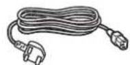
• Power cord (1.8 m)
• VGA cable (1.8 m) - RS232 cable (3.0m)
natural_image
Blank white rectangle with a thin gray border, no text or symbols present.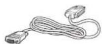
Video Signal Cable (D-SUB to D-SUB Cable)
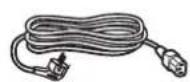
For EU*For China
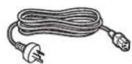

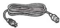
For North America* For UK
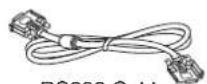
RS232 Cable

CD ROM
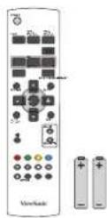
Remote Control and AAA Batteries
Quick Start Guide
* The supplied power cord varies depending on destination.
NOTES:
- For all other regions, apply a power cord that conforms to the AC voltage of the power socket and has been approved by and complies with the safety regulations of the particular country.
- You might like to save the package box and packing material for shipping the display.
1.3. Installation Notes
- Due to the high power consumption, always use the plug exclusively designed for this product. If an extended line is required, please consult your service agent.
- The product should be installed on a flat surface to avoid tipping. The distance between the back of the product and the wall should be maintained for proper ventilation. Avoid installing the product in the kitchen, bathroom or any other places with high humidity so as not to shorten the service life of the electronic components.
- The product can normally operate only under 3000m in altitude. In installations at altitudes above 3000m, some abnormalities may be experienced.
1.4. Installing and Removing Table Stands (optional)
To install table stands:
- Ensure your display is powered off.
- Spread a protective sheet on a flat surface.
- Grab the carrying handles and place the display face-down on the protective sheet.
- After inserting the stand in the guide block, tighten the screws on both sides of the display.
NOTE: The longer side of the stand should face the front of the display.
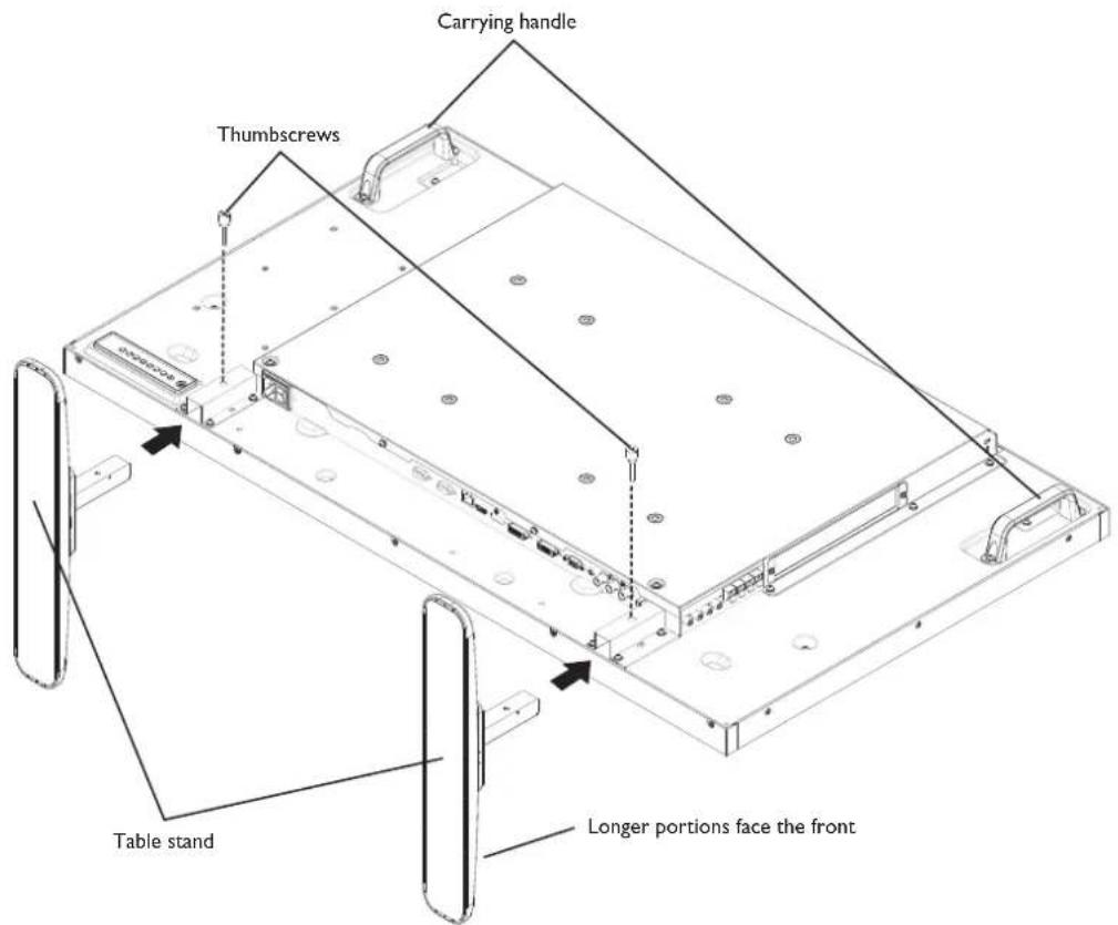
To remove table stands:
- Power off the display.
- Spread a protective sheet on a flat surface.
- Grab the carrying handles and place the display face-down on the protective sheet.
- Remove screws using a screwdriver and place them in a safe place for reuse.
1.5. Mounting on a Wall
To mount this display to a wall, you will have to obtain a standard wall-mounting kit (commercially available). We recommend using a mounting interface that complies with TUV-GS and/or UL1678 standard in North America.
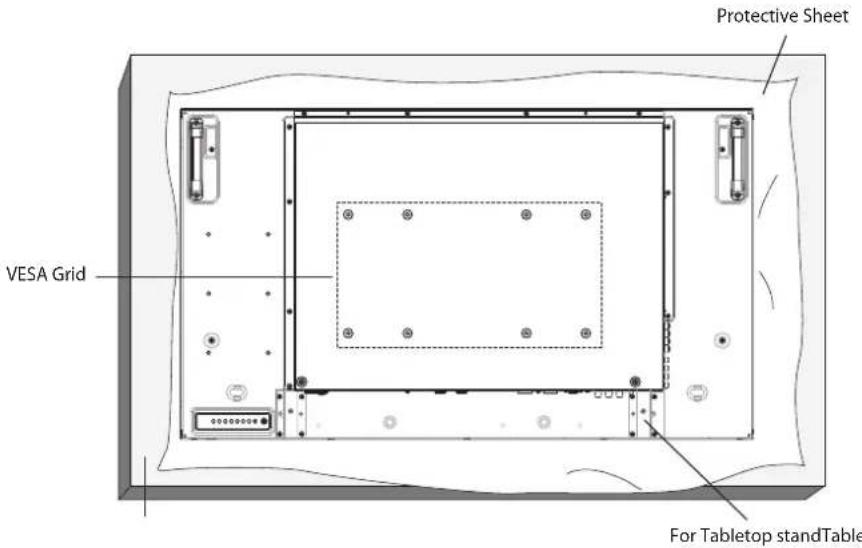
- Lay a protective sheet on a table, which was wrapped around the display when it was packaged, beneath the screen surface so as not to scratch the screen face.
- Ensure you have all accessories for mounting this display (wall mount, ceiling mount, table stand, etc).
- Follow the instructions that come with the base mounting kit. Failure to follow correct mounting procedures could result in damage to the equipment or injury to the user or installer. Product warranty does not cover damage caused by improper installation.
- For the wall-mounting kit, use M6 mounting screws (having a length 10 mm longer than the thickness of the mounting bracket) and tighten them securely.
1.5.1. VESA Grid
| CDP4260-L / CDP4262-L / CDX4652-L | 400(H) x 200(V) mm200(H) x 200(V) mm |
| CDP5560-L / CDP5562-L | 400(H) x 400(V) mm400(H) x 200(V) mm200(H) x 200(V) mm |
Caution:
To prevent the display from falling:
- For wall or ceiling installation, we recommend installing the display with metal brackets which are commercially available. For detailed installation instructions, refer to the guide received with the respective bracket.
- To lessen the probability of injury and damage resulting from fall of the display in case of earthquake or other natural disaster, be sure to consult the bracket manufacturer for installation location.
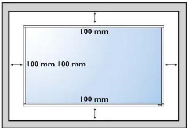
Enclosure Ventilation Requirements
To allow heat to disperse, leave space between surrounding objects as shown in the diagram below.
2. Parts and Functions
2.1. Control Panel
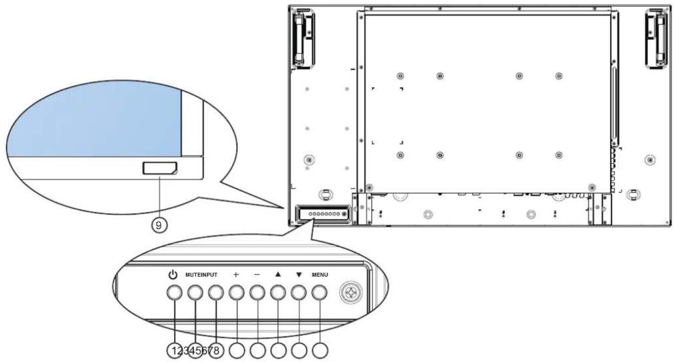
CDP4260-L/CDP4262-L/CDP5560-L/CDP5562-L:
CDX4652-L:
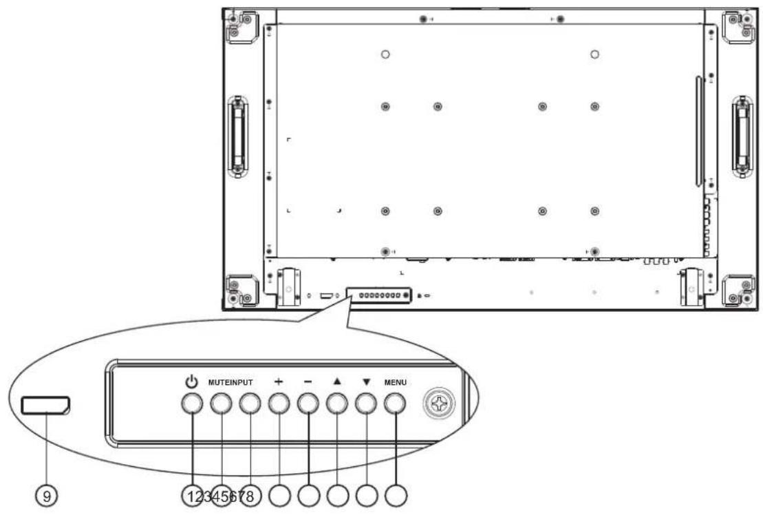
① POWER button
Use this button to turn the display on or put the display to standby.
② MUTE button
Switch the audio mute ON/OFF.
③ INPUT button
Use this button to select the input source.
④ [−] button
Increase the adjustment while OSD menu is on, or increase the audio output level while OSD menu is off.
- Used as [SET] button in the On-Screen-Display menu.
⑤ [+button
Decrease the adjustment while OSD menu is on, or decrease the audio output level while OSD menu is off.
⑥ [▲button
Move the highlight bar up to adjust the selected item while OSD menu is on.
⑦ [▼button
Move the highlight bar down to adjust the selected item while OSD menu is on.
⑧ MENU button
Return to previous menu while OSD menu is on, or to activate the OSD menu when OSD menu is off.
NOTE: "Keyboard Control Lock Mode" This function completely disables the access to all Keyboard Control functions. To enable or disable the keyboard control lock, press both [+ ] and [+ buttons and hold down continuously for more than 3 (three) seconds.
⑨ Remote control sensor and power status indicator
- Receives command signals from the remote control.
- Indicates the operating status of the display:
- Lights green when the display is turned on
- Lights red when the display is in standby mode
- Lights amber when the display enters APM mode
- When {SCHEDULE} is enabled, the light blinks green and red
- If the light blinks red, it indicates that a failure has been detected
- Lights off when the main power of the display is turned off
2.2. Input/Output Terminals
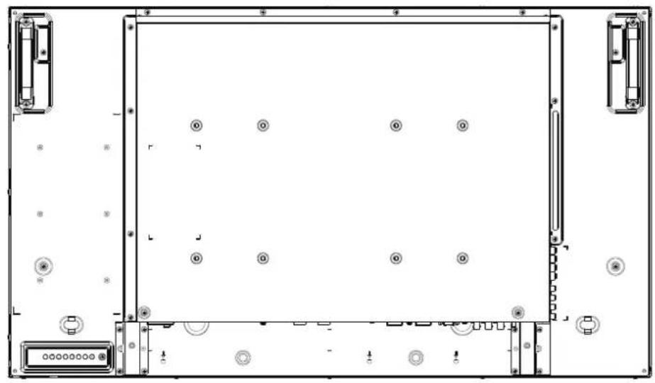
CDP4260-L/CDP4262-L/CDP5560-L/CDP5562-L:
natural_image
Front view of a computer chassis with drive bays and memory slots (no text or symbols)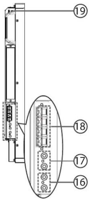

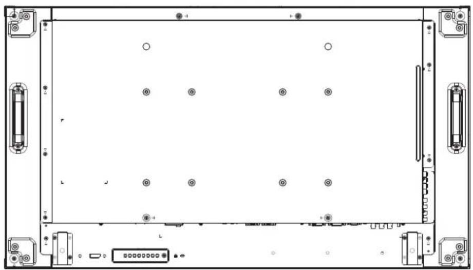
CDX4652-L:
natural_image
Front view of a computer chassis chassis with visible ports, connectors, and memory unit (no text or symbols)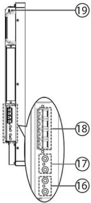
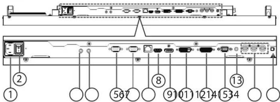
① AC IN
AC power input from the wall outlet.
② MAIN POWER SWITCH
Switch the main power on/off.
③ IR IN / ④ IR OUT (3.5 mm)
IR signal output/input for the loop-through function.
NOTES:
- This display's remote control sensor will stop working if the jack [IR IN] is connected.
- To remotely control your A/V device via this display, refer to page 14 for IR Pass Through connection.
⑤ RS232C OUT
RS232C network output for the loop-through function.
⑥ RS232C IN
RS232C network input for the loop-through function.
⑦ RJ-45
LAN port connection from your OPS device.
⑧ HDMI IN
HDMI video/audio input.
⑨ DisplayPort
DisplayPort video input.
⑩ DVI IN
DVI-D video input.
⑪ DVI OUT / VGA OUT
DVI or VGA video output.
⑫ VGA IN (D-Sub)
VGA video input.
⑬ VGA AUDIO IN
Audio input for VGA source (3.5mm stereo phone).
⑭ COMPONENT IN (BNC)
Component YPbPr video source input.
⑮ SPEAKER SWITCH
Internal speaker on/off switch.
⑯ AUDIO IN
Audio input from external AV device (RCA).
⑰ AUDIO OUT (RCA)
Audio output from the AUDIO IN jack to an external AV device.
⑱ SPEAKERS OUT
External speakers output.
⑲ KENSINGTON LOCK
Used for security and theft prevention.
2.3. Remote Control
2.3.1. General functions

① [POWER] button
Press to switch on the display from standby mode. Press again to turn it off and back into standby mode.
② [SMART] button
Press to activate Smart Menu. Press [▲] or [▼] button to select menu options. Press [SET] button to confirm and exit the selection.
- Standard: Used for normal images (factory setting)
- Highbright: Used for moving image such as Video
• sRGB: Used for text based images
③ [PIP] (Picture In Picture) button
[ON/OFF]: Turn PIP mode ON/OFF.
[INPUT]: Select the input signal for the sub-picture.
[CHANGE]: Toggle between the main picture and sub picture.
④ [CONTRAST] button
Press to activate Contrast Menu. Press [+] or [+] button to adjust the value. Press [MENU] button to confirm and exit.
⑤ [DISPLAY] button
Press to turn on/off the information OSD displayed on the upper right corner of the screen.
⑥ [+button
- Press to move the selection left in OSD menu.
- Press to decrease the value in OSD menu.
- Press to move the sub-picture left in PIP mode.
⑦ [SET] button
Press to activate the setting inside the OSD menu.
⑧ [AUTO ADJUST] button
Press to run the Auto Adjust function.
NOTE: This button is functional for VGA input only.
⑨ [ ] MUTE button
Press to turn the mute function on/off.
⑩ [VIDEO SOURCE] button
Press to toggle Video Source Menu. Press [▲] or [▼button to select one of the video sources among Displayport, DVI-D, VGA, HDMI, Component, or Video. Press [SET] button to confirm and exit.
⑪ [AUDIO SOURCE] button
Press to toggle Audio Source Menu. Press [▲] or [▼button to select one of the audio sources among Displayport, HDMI, Audio1, or Audio2. Press [SET] button to confirm and exit.
⑫ Picture Format button
Press to switch screen aspect ratio.
- For PC signal: FULL, NORMAL, CUSTOM, and REAL.
- For Video signal: FULL, NORMAL, DYNAMIC, CUSTOM, REAL, and 21:9.
⑬ [BRIGHTNESS] button
Press to toggle Brightness Menu. Press [+] or [+button to adjust the value. Press [MENU] button to confirm and exit.
⑭ [▲button
- Press to move the selection up in OSD menu.
- Press to move the sub-picture up in PIP mode.
⑮ [MENU] button
Press to turn the OSD menu on/off.
⑯ [+button
- Press to move the selection right in OSD menu.
- Press to increase the value in OSD menu.
- Press to move the sub-picture right in PIP mode.
⑰ [EXIT] button
Press to turn back to the previous OSD menu.
⑱ [▼button
- Press to move the selection down in OSD menu.
- Press to move the sub-picture down in PIP mode.
⑲ [VOL UP] button
Press to increase the audio output level.
⑳ [VOL DOWN] button
Press to decrease the audio output level.
21 COLOR buttons
(CDP/CDX Not Support)
Select tasks or options.
22 PLAY buttons (CDP/CDX Not Support)
Control playback of media files.
②3 [OPTION] button (CDP/CDX Not Support)
Access currently available options, picture and sound menus.
2.3.2. Inserting the batteries in the remote control
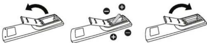
The remote control is powered by two 1.5V AAA batteries.
To install or replace batteries:
- Press and then slide the cover to open it.
- Align the batteries according to the (+) and (−) indications inside the battery compartment.
- Replace the cover.
Caution:
The incorrect use of batteries can result in leaks or bursting. Be sure to follow these instructions:
- Place "AAA" batteries matching the (+) and (−) signs on each battery to the (+) and (−) signs of the battery compartment.
- Do not mix battery types.
- Do not combine new batteries with used ones. It causes shorter life or leakage of batteries.
- Remove the dead batteries immediately to prevent them from liquid leaking in the battery compartment. Don't touch exposed battery acid, as it can damage your skin.
NOTE: If you do not intend to use the remote control for a long period, remove the batteries.
2.3.3. Handling the remote control
- Do not subject to strong shock.
- Do not allow water or other liquid to splash the remote control. If the remote control gets wet, wipe it dry immediately.
- Avoid exposure to heat and steam.
- Other than to install the batteries, do not open the remote control.
2.3.4. Operating range of the remote control
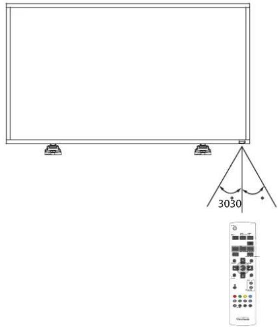
Point the top of the remote control toward the display's remote control sensor when pressing a button.
Use the remote control within a distance of less than 10m/33ft from the display's sensor, and a horizontal and vertical angle of less than 30 degrees.
NOTE: The remote control may not function properly when the remote control sensor on the display is under direct sunlight or strong illumination, or when there is an obstacle in the path of signal transmission.
3. Connecting External Equipment
3.1. Connecting External Equipment (DVD/VCR/VCD)
3.1.1. Using COMPONENT video input
![Audio Out [ R ] [ L ] [AUDIO IN] COMPONENT OUT (YPbPr) DVD / VCR / VCD [COMPONENT IN] (Pr/Pb/Y)](/content/2026/06/1146052/images/a1e3485fdacf82a823020c46b74c258099b587295f31fae0fde90fa9b57b1331.jpg)
3.1.2. Using HDMI video input
![DVD / VCR / VCD HDMI Out [HDMI IN]](/content/2026/06/1146052/images/65ac4422fe4902f453ba479a1b01424626333083b2e1211edc2f5ab5adf665f7.jpg)
3.2. Connecting a PC
3.2.1. Using VGA input
![[R] [L] [AUDIO IN] VGA Out D-Sub 15 pin PC Audio Out [VGA IN] [VGA AUDIO IN]](/content/2026/06/1146052/images/4ea0641c678acc79afb24f15ec214e84b9175a3c21f31b451cdc951242afb822.jpg)
3.2.2. Using DVI input
![[AUDIO IN] [R] [L] DVI IN [DVI OUT] PC Audio Out [VGA AUDIO IN]](/content/2026/06/1146052/images/3f19d333462382761d36f2caa43692d1855f2197c7191bf816012c47a8b02f8b.jpg)
3.2.3. Using HDMI input
![HDMI Out [HDMI IN] PC](/content/2026/06/1146052/images/c1de20db4ba22bfe38d596602c92a4868e51e669fb7b0e3ee354b72f25c375a0.jpg)
3.3. Connecting Audio Equipment
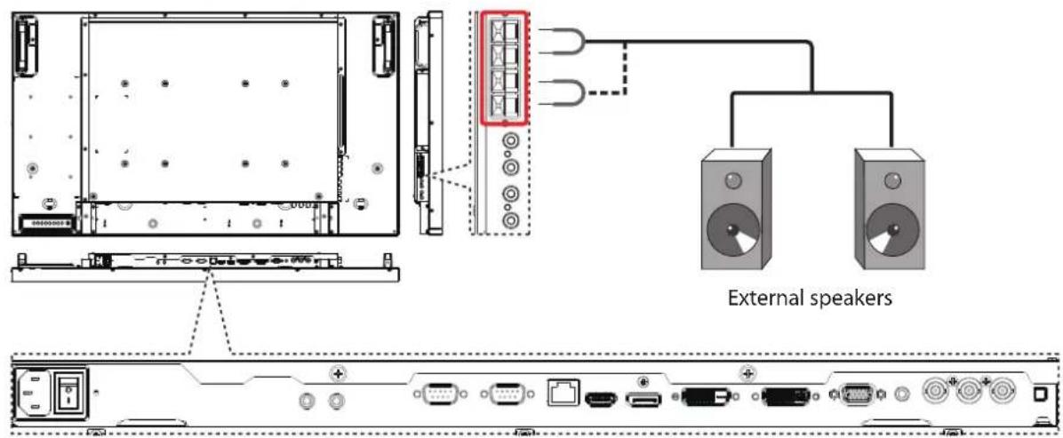
3.3.1. Connecting external speakers
3.3.2. Connecting an external audio device
![[R] [L] [AUDIO OUT] Audio In Stereo Amplifier](/content/2026/06/1146052/images/34bd3f04670a2f79abd9b881b79c374cccc60fc6e91edd3478c39a7fb68ee70d.jpg)
3.4. Connecting Multiple Displays in a Daisy-chain Configuration
You can interconnect multiple displays to create a daisy-chain configuration for applications such as a video wall.
NOTE: Maximum 25 displays (5x5) can be used in a daisy-chain configuration.
3.4.1. Display control connection
Connect the [RS232C OUT] connector of DISPLAY 1 to the [RS232C IN] connector of DISPLAY 2.
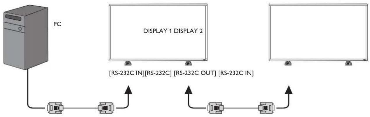
flowchart
graph TD
    A["PC"] --> B["RS-232C IN"]
    B --> C["RS-232C OUT"]
    C --> D["RS-232C IN"]
    D --> E["RS-232C OUT"]
    E --> F["RS-232C IN"]
    F --> G["RS-232C OUT"]
    G --> H["RS-232C IN"]
    H --> I["RS-232C OUT"]
    I --> J["RS-232C IN"]
    J --> K["RS-232C OUT"]
    K --> L["RS-232C IN"]
    L --> M["RS-232C OUT"]
    M --> N["RS-232C IN"]
    N --> O["RS-232C OUT"]
    O --> P["RS-232C IN"]
    P --> Q["RS-232C OUT"]
    Q --> R["RS-232C IN"]
    R --> S["RS-232C OUT"]
    S --> T["RS-232C IN"]
    T --> U["RS-232C OUT"]
    U --> V["RS-232C IN"]
    V --> W["RS-232C OUT"]
    W --> X["RS-232C IN"]
    X --> Y["RS-232C OUT"]
3.4.2. Digital video connection
Connect the [DVI OUT / VGA OUT] connector of DISPLAY 1 to the [DVI IN] connector of DISPLAY 2.
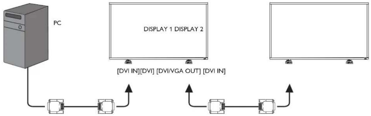
flowchart
graph TD
    A["PC"] --> B["Display 1 DISPLAY 2"]
    B --> C["[DVI IN"][DVI] [DVI/VGA OUT] [DVI IN]]
    C --> D["Output"]
    style A fill:#f9f,stroke:#333
    style B fill:#bbf,stroke:#333
    style C fill:#dfd,stroke:#333
    style D fill:#dfd,stroke:#333
3.4.3. Analog video connection
Connect the [DVI OUT / VGA OUT] connector of DISPLAY 1 to the [VGA IN] connector of DISPLAY 2.
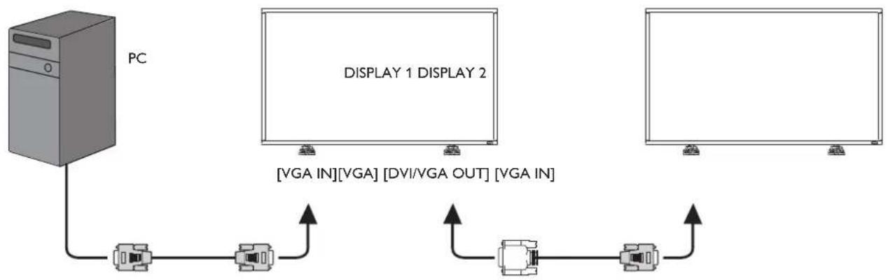
flowchart
graph TD
    PC["PC"] -->|VGA IN| Display1["DISPLAY 1 DISPLAY 2"]
    Display1 -->|DVI/VGA OUT| Display2["DISPLAY 2"]
    Display2 -->|VGA IN| Display3["DISPLAY 3"]
    Display3 -->|VGA IN| Display4["DISPLAY 4"]
3.4.4. IR connection (optional)
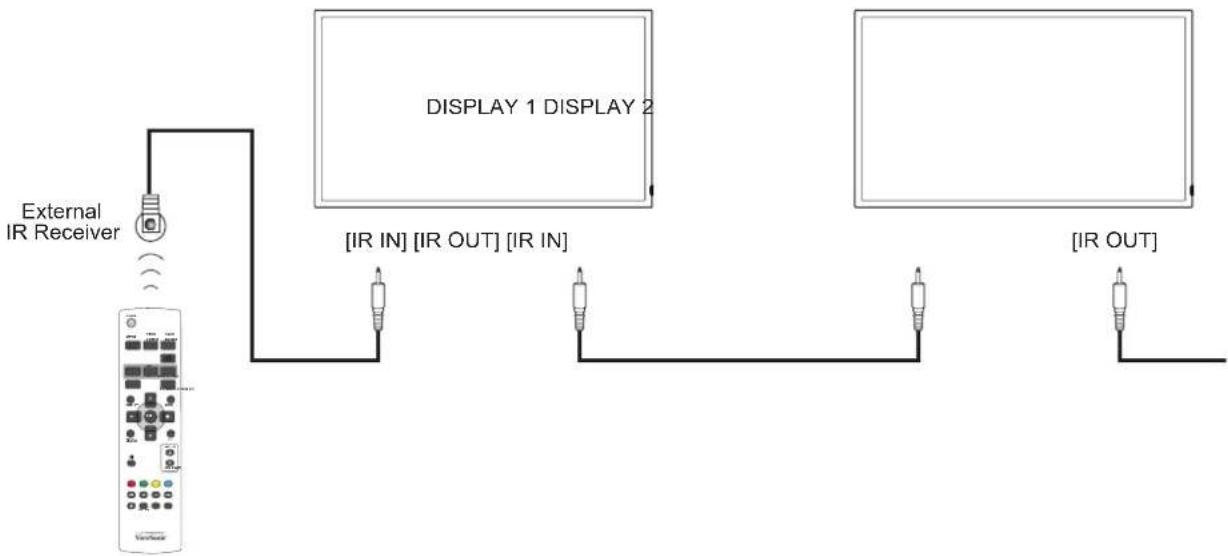
flowchart
graph TD
    A["External IR Receiver"] --> B["Display 1 DISPLAY 2"]
    B --> C["[IR IN"] [IR OUT] [IR IN]]
    C --> D["[IR OUT"]]
NOTE: This display's remote control sensor will stop working if the [IR IN] is connected.
3.5. IR Pass-through Connection (optional)
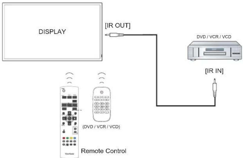
flowchart
graph TD
    A["DISPLAY"] -->|IR OUT| B["DVD / VCR / VCD"]
    B --> C["IR IN"]
    D["Remote Control"] --> E["(DVD / VCR / VCD)"]
    E --> F["Display"]
4. OSD Menu
An overall view of the On-Screen Display (OSD) structure is shown below. You can use it as a reference for further adjusting your display.
4.1. Navigating the OSD Menu
4.1.1. Navigating the OSD menu using the remote control
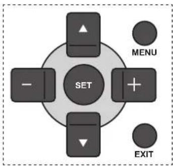
flowchart
graph TD
    A["SET"] --> B["▲"]
    A --> C["+"]
    A --> D["▼"]
    A --> E["−"]
    F["MENU"] --> A
    G["EXIT"] --> A
- Press [MENU] button on the remote control to display the OSD menu.
- Press [▲] or [▼button to choose the item you want to adjust.
- Press [SET] button to enter the submenu.
- In the submenu, press [▲] or [▼button to toggle among items, press [+] or [+button to adjust settings. If there is a submenu, press [SET] button to enter the submenu.
- Press [EXIT] button to return to the previous menu, or press [MENU] button to exit the OSD menu.
4.1.2. Navigating the OSD menu using the display's control buttons
- Press [MENU] button to display the OSD menu.
- Press [+] or [+button to choose the item you want to adjust.
- Press [SOURCE] button to enter the submenu.
- In the submenu, press [▲] or [▼button to toggle among items, press [+] or [+button to adjust settings. If there is a submenu, press [SOURCE] button to enter the submenu.
- Press [MENU] button to return to the previous menu, or press [MENU] button several times to exit the OSD menu.
4.2. OSD Menu Overview
4.2.1. PICTURE menu
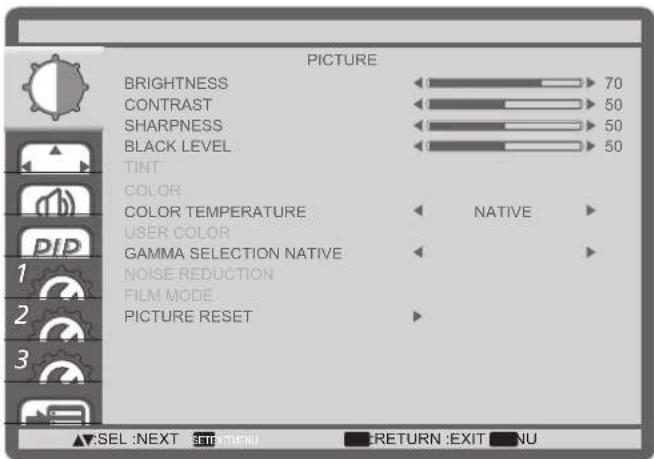
BRIGHTNESS
Adjust the overall image brightness by changing the intensity of the LCD panel's backlight.
CONTRAST
Adjust to sharpen the picture quality. The black portions of the picture become richer in darkness and the white become brighter.
SHARPNESS
Adjust to improve the image detail.
BLACK LEVEL
Adjust to change the image brightness.
TINT
Use the [+] or [+] -button to adjust. Press the [+] -button and the flesh tone color turns slightly green. Press the [+] -button and the flesh tone color turns slightly purple.
NOTE: This item is functional for HDMI (Video mode), Video, and YPbPr inputs only.
COLOR
Adjust to increase or decrease the intensity of colors in the image.
NOTE: This item is functional for HDMI (Video mode), Video, and YPbPr inputs only.
COLOR TEMPERATURE
Select a color temperature for the image. A lower color temperature will have a reddish tint, whilst a higher color temperature gives off a more bluish tint.
The options are: {3000K} / {4000K} / {5000K} / {6500K} / {7500K} / {9300K} / {10000K} / {NATIVE} / {USER}.
USER COLOR
With this function you can adjust the color tones of the image precisely by changing the R (Red), G (Green) and B (Blue) settings independently.
NOTE: This item is functional only when {COLOR TEMPERATURE} is set to {USER}.
GAMMA SELECTION
Gamma is what controls the overall brightness of an image. Images which are not corrected properly can appear too white or too dark, so controlling the gamma properly can have a huge influence on the overall picture quality of your display.
The options are: {NATIVE} / {2.2} / {2.4} / {S GAMMA}.
NOISE REDUCTION
Adjust to remove the noise in the image. You can select a suitable noise reduction level.
The options are: {OFF} / {LOW} / {MIDDLE} / {HIGH}.
NOTE: This item is functional for HDMI(Video mode), Video, and YPbPr inputs only.
FILM MODE
Choose to turn on or off the film mode frame conversion function.
- {AUTO} - Enable the film mode frame conversion function for movies and motion pictures. The display converts a 24 frames-per-second (24 fps) input signal format to DVD video signal format. Once this function is enabled, it is recommended that you set the {SCAN CONVERSION} function to {PROGRESSIVE}.
- {OFF} - Disable the film mode frame conversion function. This mode is suitable for TV broadcasting and VCR signals.
PICTURE RESET
Reset all settings in the Picture menu to factory preset values.
4.2.2. SCREEN menu
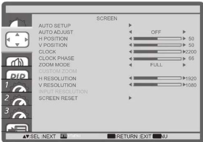
AUTO SETUP
Use this function to let the display automatically optimize the display of VGA input image.
NOTE: This item is functional for VGA input only.
AUTO ADJUST
Choose to let the display detect and display available signal sources automatically.
- {ON} - Set the display to display the image automatically once a signal is connected.
- {OFF} - Once a signal is connected, it can only be selected manually.
H POSITION
Press the [+] button to move the image to the right, or [+] -to move the image to the left.
V POSITION
Press the [+] button to move the image up, or [+] to move the image down.
CLOCK
Adjust the width of the image.
NOTE: This item is functional for VGA input only.
CLOCK PHASE
Adjust to improve the focus, clarity and stability of the image.
NOTE: This item is functional for VGA input only.
ZOOM MODE
The pictures you receive may be transmitted in 16:9 format (wide screen) or 4:3 format (conventional screen). The 16:9 pictures sometimes have a black band at the top and bottom of the screen (letterbox format).
This function allows you to optimize the picture display on screen. The following zoom modes are available for:
- PC mode: {FULL} / {NORMAL} / {CUSTOM} / {REAL}.
- Video mode: {FULL} / {NORMAL} / {DYNAMIC} / {CUSTOM} / {REAL}.
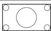
FULL
This mode restores the correct proportions of pictures transmitted in 16:9 using the full screen display.
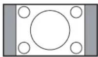
NORMAL
The picture is reproduced in 4:3 format and a black band is displayed on either side of the picture.
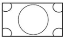
DYNAMIC
Fill the entire screen by stretching 4:3 pictures non-proportionally.
CUSTOM
Choose to apply the custom zoom settings in the Custom Zoom submenu.
REAL
This mode displays the image pixel-by-pixel on screen without scaling the original image size.
CUSTOM ZOOM
You can use this function to further customize the zoom settings to suit the image you want to display.
NOTE: This item is functional only when the {ZOOM MODE} setting is set to {CUSTOM}.
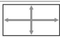
ZOOM
Expands the horizontal and vertical sizes of the image simultaneously.
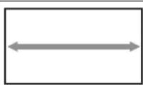
H ZOOM
Expands the horizontal size of the image only.
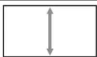
V ZOOM
Expands the vertical size of the image only.
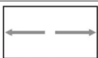
H POSITION
Moves the horizontal position of the image left or right.
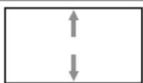
V POSITION
Moves the vertical position of the image up or down.
INPUT RESOLUTION
Set the resolution of the VGA input. This is only required when the display is unable to detect the VGA input resolution correctly.
NOTE: This item is functional for VGA input only.
The options are:
• {1024x768 / 1280x768 / 1360x768}
• {1400x1050 / 1680x1050}
• {1600x1200 / 1920x1200}
• {Auto}: Determines the resolution automatically.
The selected settings will become effective after turning off the power and turn it on again.
SCREEN RESET
Reset all settings in the SCREEN menu to factory preset values.
4.2.3. AUDIO menu
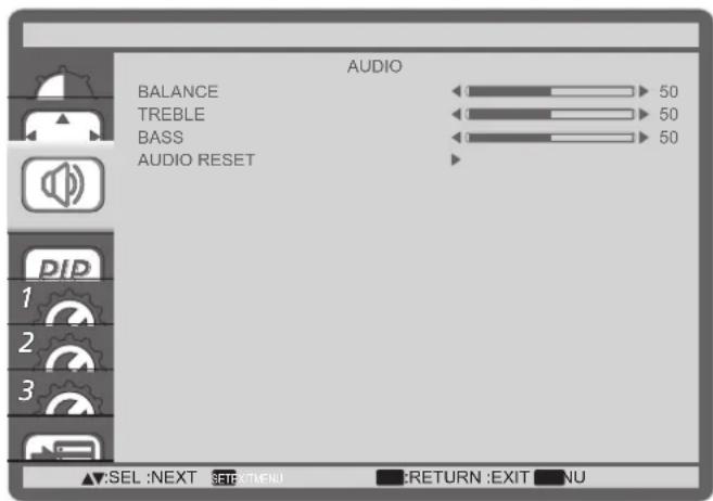
BALANCE
Adjust to emphasize left or right audio output balance.
TREBLE
Adjust to increase or decrease higher-pitched sounds.
BASS
Adjust to increase or decrease lower-pitched sounds.
AUDIO RESET
Reset all settings in the AUDIO menu to factory preset values.
4.2.4. PIP menu
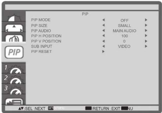
PIP MODE
Select the PIP (Picture-in-Picture) mode.
The options are: {OFF} / {PIP} / {POP} / {SBS ASPECT} / {SBS FULL}.
PIP SIZE
Select the size of the sub picture in the PIP (Picture-in-Picture) mode.
The options are: {SMALL} / {MIDDLE} / {LARGE}.
PIP AUDIO
Select the audio source in the PIP (Picture-in-Picture) mode.
- {MAIN AUDIO} - Select audio from the main picture
- {SUB AUDIO} - Select audio from the sub picture.
PIP H POSITION
Adjust the horizontal placement of the sub picture.
PIP V POSITION
Adjust the vertical placement of the sub picture.
SUB INPUT
Select the input signal for the sub-picture.
PIP RESET
Reset all settings in the PIP menu to factory preset values.
NOTES:
- The PIP function is available only for certain signal source combinations as shown in the table below.
- The availability of the PIP function will also depend on the resolution of the input signal being used.
| Sub Picture\Main Picture | DVI VGA | HDMI YPb | Pr Video | ||
| DVI X X X X O | |||||
| VGA X X X X O | |||||
| HDMI X X X X O | |||||
| YPbPr X X X X O | |||||
| Video | O | O | O | O | X |
(O: PIP function available, X: PIP function unavailable)
By pressing the [PIP ON/OFF] button on the remote control, you can change the mode in the order shown below:

flowchart
graph LR
    A["PIP"] --> B["POP"]
    B --> C["SBS ASPECT"]
    C --> D["SBS FULL"]
    D --> E["OFF"]
    E --> F["A"]
    style A fill:#f9f,stroke:#333
    style B fill:#f9f,stroke:#333
    style C fill:#f9f,stroke:#333
    style D fill:#f9f,stroke:#333
    style E fill:#f9f,stroke:#333
The resolutions in the PIP and POP modes are configured as follows:
PIP SIZE {SMALL} : 320 x 240 pixels
{MIDDLE}: 480 x 320 pixels
{LARGE} : 640 x 480 pixels
POP SIZE: 474 x 355 pixels
NOTE: The images displayed in the sub picture always fit the PIP sizes shown above irrespective of the aspect ratio of the input image.
4.2.5. CONFIGURATION1 menu
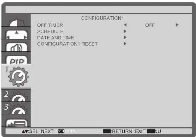
OFF TIMER
Set the display to turn itself off to standby mode within an amount of time specified.
The options are: {OFF, 1HOUR \~ 24HOURS} from current time.
SCHEDULE
This function allows you to program up to 7 (seven) different scheduled time intervals for the display to activate.
You can select:
- The time for the display to turn on and turn off.
- The days in a week for the display to activate.
- Which input source the display will use for each scheduled activation period.
NOTE: You should set up current date and time in {DATE AND TIME} menu before using this function.
- Press [SET] button to enter the submenu.
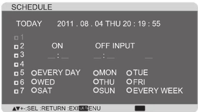
- Press [▲ or [ ]▼ button to select a schedule item (item number 1 \~ 7), and then press [SET] button to mark it the item number.
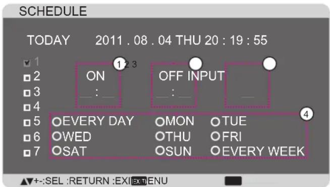
- Press [+] or [ ] button to select the schedule:
① POWER-ON schedule: Press [▲or [ ]▼ button to set the hour and minute for the display to turn on.
② POWER-OFF schedule: Press [▲or [ ]▼ button to set the hour and minute for the display to turn off.
Select or leave an empty “__” for both the hour and minute slot if you do not want to use this power-on or power-off schedule.
③ INPUT-SOURCE selection: Press [▲] or [▼] button to select an input source. If no input source is selected, the input source will remain the same as last selected.
④ DATE schedule: Press [+] button to select which day in a week this schedule item will be take effect, and then press the [SET] button.
- For more schedule settings, press [EXIT] button and then repeat the steps above. A check mark in the box next to the number of the schedule item indicates that the selected schedule is in effect.
NOTES:
- The {EVERY DAY} selection in a schedule item takes priority over the other weekly schedules.
- If the schedule overlap, the scheduled power-on time takes priority over scheduled power-off time.
- If there are two schedule items programmed for the same time, the highest numbered schedule takes priority. For example, if schedule items #1 and #2 both set the display to power on at 7:00 AM and off at 5:00 PM, then only schedule item #1 will take effect.
DATE AND TIME
Adjust the current date and time for the display's internal clock.
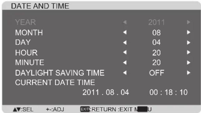
- Press [SET] button to enter the submenu.
- Press [▲] or [▼button to toggle among the {YEAR}, {MONTH}, {DAY}, {HOUR}, {MINUTE}, and {DAYLIGHT SAVING TIME} settings.
- Press [+] or [+button to adjust all settings except {DAYLIGHT SAVING TIME}.
CONFIGURATION1 RESET
Reset all settings in the CONFIGURATION1 menu to factory preset values.
4.2.6. CONFIGURATION2 menu
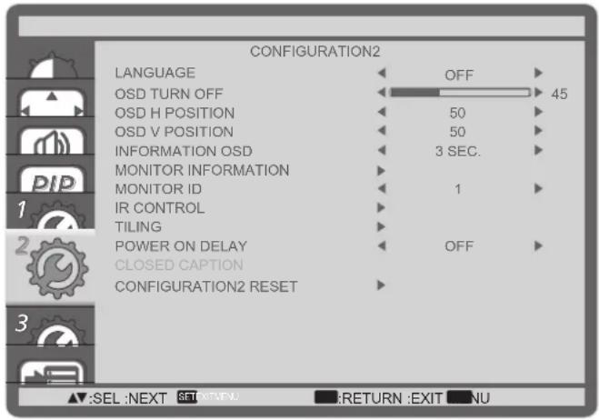
LANGUAGE
Select the language used in the OSD menu.
The options are: {ENGLISH} / {DEUTSCH}
{FRANÇAIS} / {ITALIANO} / ESPAÑOL SVENSKA
Set the period of time the OSD menu stays on the screen.
The options are: 5 120 seconds.
OSD H POSITION
Adjust the horizontal position of the OSD menu.
OSD V POSITION
Adjust the vertical position of the OSD menu.
INFORMATION OSD
Set the period of time the information OSD displayed on the upper right corner of the screen.
The information OSD will display when input signal is changed.
The information OSD will remain on the screen with {OFF} selection.
The options are: {OFF, 3 SEC. \~ 10 SEC.}.
MONITOR INFORMATION
Displays the information about your display, including MODEL NAME and SERIAL.
MONITOR ID
Set the ID number for controlling the display via the RS232C connection. Each display must have a unique ID number when multiple sets of this display are connected.
IR CONTROL
Select the operation mode of the remote control unit when multiple displays are connected via the RS232C connection.
- {NORMAL} - All displays can be operated normally by the remote control.
- {LOCK} - Lock the remote control function of this display. To unlock, press and hold the [DISPLAY] button on the remote control for 5 (five) seconds.
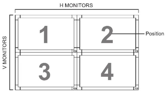
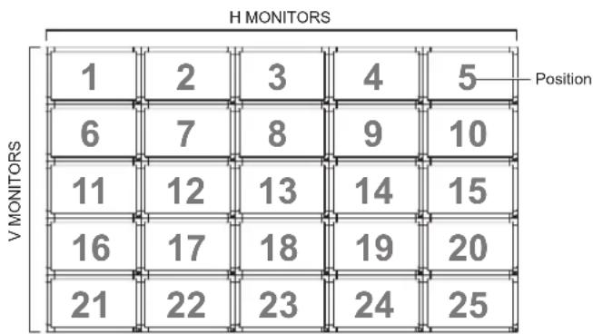
TILING
With this function you can create a single large-screen matrix (video wall) that consists of up to 25 sets of this display (up to 5-set each at the vertical and horizontal side). This function requires a daisy-chain connection.
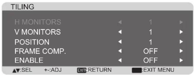
Example: 2 x 2 screen matrix (4 displays)
H MONITORS = 2 displays
V MONITORS = 2 displays
Example: 5 x 5 screen matrix (25 displays)
H MONITORS = 5 displays
V MONITORS = 5 displays
other
H MONITORS | Position | V MONITORS | |---|---| | 1 | 6 | | 2 | 7 | | 3 | 8 | | 4 | 9 | | 5 | 10 | | 11 | 12 | | 12 | 13 | | 13 | 14 | | 14 | 15 | | 16 | 17 | | 17 | 18 | | 18 | 19 | | 19 | 20 | | 20 | 21 | | 21 | 22 | | 22 | 23 | | 23 | 24 | | 24 | 25 | Position indicated by label on the top row.-
H MONITORS - Select the number of displays on the horizontal side.
• V MONITORS - Select the number of displays on the vertical side. -
POSITION - Select the position of this display in the screen matrix.
- FRAME COMP. - Choose to turn the frame compensation function on or off. If turned on, the display will adjust the image to compensate for the width of the display bezels in order to accurately display the image.
- ENABLE: Choose to enable or disable the Tiling function. If enabled, the display will apply the settings in {H MONITORS}, {V MONITORS}, {POSITION}, and {FRAME COMP.}.
NOTE: The Tiling function will be disabled when the [ON/OFF] button for PIP is pressed.
POWER ON DELAY
Select the delayed time until the power-on mode is activated after the power is turned on manually or automatically. This setting is useful in hiding start-up messages and powering on the connected devices at different timings.
The options are: {OFF}, {2 SEC.}, {4 SEC.}, {6 SEC.}, {8 SEC.}, {10 SEC.}, {20 SEC.}, {30 SEC.}, {40 SEC.}, {50 SEC.}.
CLOSED CAPTION
Choose to display or hide captions.
NOTE: This item is functional for VIDEO input only.
- {OFF} - Captions are hidden.
- {CC1} - Captions are displayed in sync with the primary audio.
- {CC2} - Information (related to the primary audio) is displayed without sync.
- {CC3} - Captions are displayed in sync with the secondary audio.
- {CC4} - Information (related to the secondary audio) is displayed without sync.
- {TT1 / TT2 / TT3 / TT4} - Four types of information not related to the displayed images are displayed. (For example, news and weather forecast.)
NOTE: Check with each supplier of your video software and external video devices in advance whether they are compliant with EIA-608-A. If their video signals are not compliant with it, images may not be displayed correctly.
CONFIGURATION2 RESET
Reset all settings in the CONFIGURATION2 menu to factory preset values.
4.2.7. CONFIGURATION3 menu
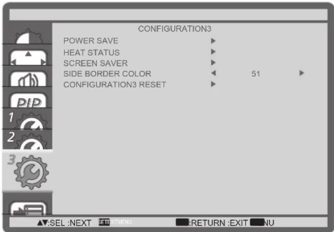
POWER SAVE
Set the display to reduce the power automatically.
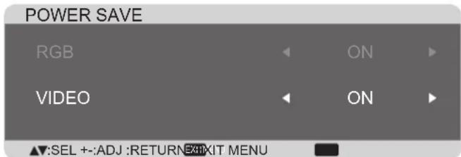
- {RGB} - Select {ON} to let the display enter DPMS mode with no signal detected from the HDMI Graphic mode, HDMI, DVI-D, or VGA inputs after three successive cycles.
- {VIDEO} - Select {ON} to let the display enter power saving mode with no signal detected from the HDMI Video mode or YPbPr inputs after three successive cycles.
HEAT STATUS
This function allows you to check the thermal status of the display at any time.
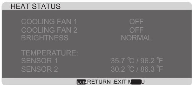
SCREEN SAVER
Choose to enable the panel saving functions to reduce the risk of the "image persistence".
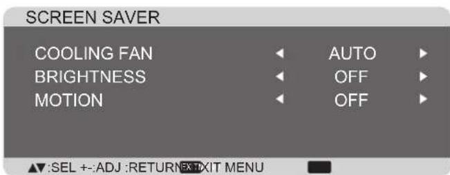
- {COOLING FAN} - Select {ON} to turn on the cooling fan all the time. Select {AUTO} to turn on/off the cooling fan according to the display's temperature.
NOTES:
- The default {AUTO} option will start running the cooling fan if the temperature of 65^ C ( 152^ F) is reached, and will keep running for 30 minutes after cooling down to the temperature of 62^ C ( 144^ F).
-
A temperature-warning message will be shown on the screen once the temperature reaches 79°C. All key function except [Power] key will then be disabled.
-
{BRIGHTNESS} - Select {ON} and the brightness of the image will be reduced to an appropriate level, and the Brightness setting in the Picture menu will become unavailable.
- {MOTION} - Select the time interval ({10 \~ 900} Seconds / {OFF}) for the display to slightly expand the image size and shift the position of pixels in four directions (up, down, left, or right).
SIDE BORDER COLOR
Adjust the brightness of the black areas displayed on both sides of 4:3 images.
CONFIGURATION3 RESET
Reset all settings in the CONFIGURATION3 menu to factory preset values.
4.2.8. ADVANCED OPTION menu
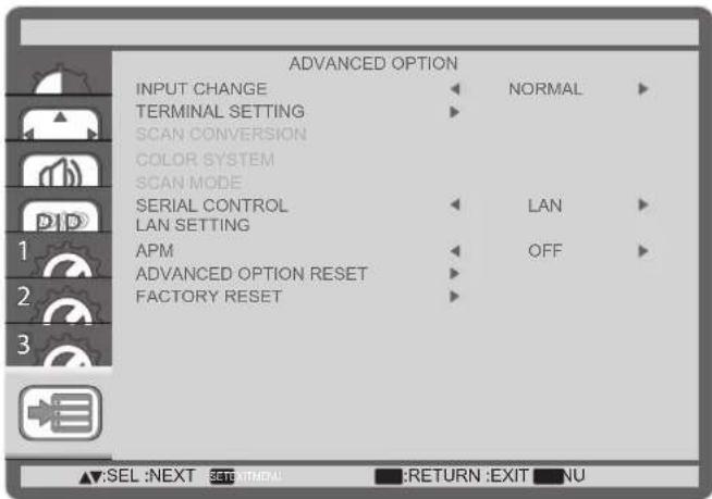
INPUT CHANGE
Select the time for input switching as {NORMAL} or {QUICK}.
NOTE: The selection {QUICK} may cause a slight noise.
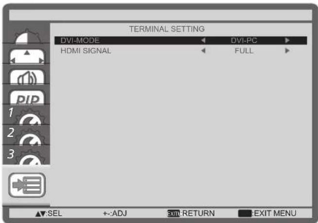
TERMINAL SETTING
Select the mode to display the HDMI or DVI signal according to their signal format depending on their source device.
• {DVI MODE}: Used for DVI-D signal.
- Select {DVI-PC} when the source device is a PC.
- Select {DVI-HD} when the source device is a video device.
• {HDMI SIGNAL}: Used for HDMI signal.
- Select {LIMITED} when displaying the signal that uses 16 to 235 levels of 256 levels for each R, G, and B.
- Select {FULL} when displaying the signal that uses all 256 levels (from level 0 to 255).
SCAN CONVERSION
Choose to enable or disable the IP (Interlace to Progressive) conversion function.
- {PROGRESSIVE} - Enable the IP conversion function (recommended). Once enabled, the interlace input signal will be converted to progressive format for better display quality.
- {INTERLACE} - Disable the IP function. This mode is suitable for displaying motion pictures, but it increases the chance of image retention.
COLOR SYSTEM
Selects the Color System depending on your input video format.
The options are: {AUTO} / {NTSC} / {PAL} / {SECAM} / {4.43NTSC} / {PAL-60}.
NOTE: This item is functional for VIDEO input only.
SCAN MODE
Change the display area of the image.
- {OVERSCAN} - Display about 95% of the original size of the image. The rest of the areas surrounding the image will be cut off.
- {UNDERSCAN} - Display the image in its original size.
NOTE: This item is functional for HDMI-Video timing input only.
SERIAL CONTROL
Select the network control port.
The options are: {RS-232C} / {LAN}.
NOTE: If {LAN} is selected, then {RS-232C} will not be activated, even if a cable is attached, and vice versa.
LAN SETTING
Assign {IP ADDRESS}, {SUBNET MASK}, and {DEFAULT GATEWAY} for the display.
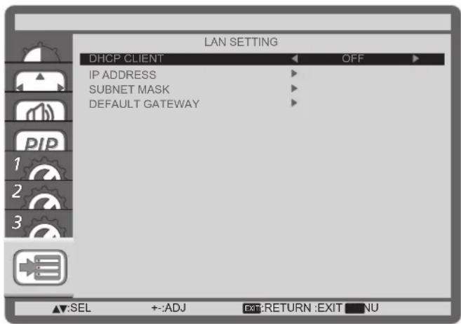
- DHCP - Choose to enable or disable the DHCP function. If enabled, the display will be assigned IP address, Subnet mask and Default gateway automatically. If disabled, you will be prompted to enter the following value manually. Finally, press [SET] button to store and save the chosen values.
APM
{ON} - Power & function recover when either H & V syncs or digital clock are detected.
{OFF} - It must be used power key by remote control or Keypad. There is no Wake On LAN.
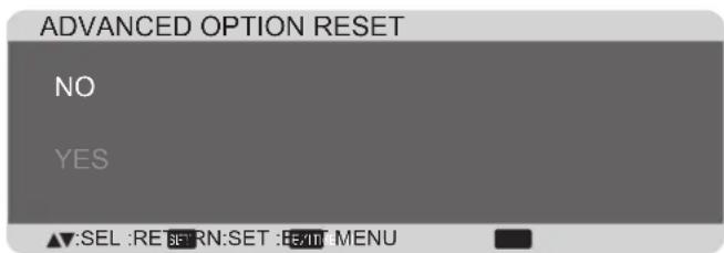
ADVANCED OPTION RESET
Reset all settings in the ADVANCED OPTION menu to factory preset values.
- Press [SET] button to enter the submenu.
- Press [▲] or [▼button to select {YES}, and then press [SET] button to do the reset.
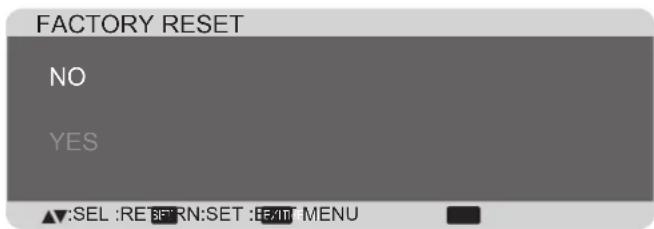
FACTORY RESET
Reset all OSD menu settings ( PICTURE , SCREEN , AUDIO , PIP , CONFIGURATION1 , CONFIGURATION2 , CONFIGURATION3 , and ADVANCED OPTION ) to factory preset values.
- Press [SET] button to enter the submenu.
- Press [▲] or [▼button to select {YES}, and then press [SET] button to do the reset.
5. Input Mode
VGA Resolution:
| Standard Resolution | Active Resolution | Refresh Rate | Pixel Rate Aspect | Ratio Stand for Mode | ||
| H Pixels V Lines | ||||||
| VGA 640 | 480 60 Hz | 25.175 MHz | 4:3 Video Graphic Array480 72 Hz 31.5 MH | |||
| 480 75 Hz | 31.5 MHz | |||||
| WVGA 720 400 | 70 Hz 33.75 | MHz 16:9 | Wide Video Graphic Array | |||
| SVGA | 800 | 600 60 Hz | 40 MHz | 4:3 Super VGA | ||
| 600 75 Hz | 49.5 MHz | |||||
| XGA 1024 | 768 60 Hz | 65 MHz | 4:3 | Extended Graphic Array | ||
| 768 75 Hz | 78.75 MHz | |||||
| WXGA | 1280 | 768 | 60 Hz | 79.5 MHz | 5:3 | Wide XGA |
| WXGA | 1280 | 800 | 60 Hz | 79.5 MHz | 16:10 | Wide XGA |
| SXGA | 1280 | 960 | 60 Hz | 108 MHz | 4:3 | Super XGA |
| SXGA | 1280 | 1024 | 60 Hz | 108 MHz | 5:4 | Super XGA |
| WXGA | 1360 | 768 | 60 Hz | 85.5 MHz | 16:9 | Wide XGA |
| WXGA | 1366 | 768 | 60 Hz | 85.5 MHz | 16:9 | Wide XGA |
| UXGA | 1600 | 1200 | 60 Hz | 162 MHz | 4:3 | Ultra XGA |
| HD1080 | 1920 | 1080 | 60 Hz | 148.5 MHz | 16:9 | HD1080 |
SDTV Resolution:
| Standard Resolution | Active Resolution | Refresh Rate | Pixel Rate Aspect | Ratio Stand for Mode | ||
| H Pixels V Lines | ||||||
| 480i | 720 480 | 29.97 Hz | 13.5 MHz | 4:3 | Modified NTSC Standard | |
| 480p | 59.94 Hz | 27 MHz | ||||
| 576i | 720 480 | 25 Hz | 13.5 MHz | 4:3 | Modified PAL Standard | |
| 576p | 50 Hz | 27 MHz | ||||
HDTV Resolution:
| Standard Resolution | Active Resolution | Refresh Rate | Pixel Rate Aspect | Ratio Stand for Mode | |
| H Pixels V Lines | |||||
| 720p | 1280 | 720 | 50 Hz | 74.25 MHz | 16:9 Normally DVB Mode |
| 60 Hz | |||||
| 1080i | 1920 | 1080 | 25 Hz | 74.25 MHz | 16:9 Normally ATSC Mode |
| 30 Hz | |||||
| 1080p | 1920 | 1080 | 50 Hz | 148.5 MHz | 16:9 Normally ATSC Mode |
| 60 Hz | |||||
• The quality of PC text is optimal in HD 1080 mode (1920 x 1080, 60Hz).
- Your PC display screen might appear different depending on the manufacturer (and your particular version of Windows).
- Check your PC instruction book for information about connecting your PC to a display.
- If a vertical and horizontal frequency-select mode exists, select 60Hz (vertical) and 31.5KHz (horizontal). In some cases, abnormal signals (such as stripes) might appear on the screen when the PC power is turned off (or if the PC is disconnected). If so, press the [INPUT] button to enter the video mode. Also, make sure that the PC is connected.
- When horizontal synchronous signals seem irregular in RGB mode, check PC power saving mode or cable connections.
- The display settings table complies with IBM/VESA standards, and based on the analog input.
- The DVI support mode is regarded to be the same as the PC support mode.
- The best vertical frequency timing for each mode is 60Hz.
6. Cleaning and Troubleshooting
6.1. Cleaning
When Using the Display
- Do not bring your hands, face or objects close to the ventilation holes of the display. The top of the display is usually very hot due to the high temperature of exhaust air being released through the ventilation holes. Burns or personal injuries may occur if any body parts are brought too close. Placing any object near the top of the display could also result in heat related damage to the object as well as the display itself.
- Be sure to disconnect all cables before moving the display. Moving the display with its cables attached may damage the cables and thus cause fire or electric shock.
- Disconnect the power plug from the wall outlet as a safety precaution before carrying out any type of cleaning or maintenance procedure.
Front Panel Cleaning Instructions
- The front of the display has been specially treated. Wipe the surface gently using only a cleaning cloth or a soft, lint-free cloth.
- If the surface becomes dirty, soak a soft, lint-free cloth in a mild detergent solution. Wring the cloth to remove excess liquid. Wipe the surface of the display to remove dirt. Then use a dry cloth of the same type to dry.
- Do not scratch or hit the surface of the panel with fingers or hard objects of any kind.
- Do not use volatile substances such as insert sprays, solvents and thinners.
Cabinet Cleaning Instructions
- If the cabinet becomes dirty, wipe the cabinet with a soft, dry cloth.
- If the cabinet is extremely dirty, soak a lint-free cloth in a mild detergent solution. Wring the cloth to remove as much moisture as possible. Wipe the cabinet. Use another dry cloth to wipe over until the surface is dry.
- Do not allow any water or detergent to come into contact with the surface of the display. If water or moisture gets inside the unit, operating problems, electrical and shock hazards may result.
- Do not scratch or hit the cabinet with fingers or hard objects of any kind.
- Do not use volatile substances such as insert sprays, solvents and thinners on the cabinet.
• Do not place anything made from rubber or PVC near the cabinet for any extended periods of time.
6.2. Troubleshooting
| Symptom Possible Cause Remedy | ||
| No picture is displayed 1. The power cord is disconnected.2. The main power switch on the back of the display is not switched on.3. The selected input has no connection.4. The display is in standby mode. | Plug in the power cord.Make sure the power switch is switched on.Connect a signal connection to the display. | |
| Interference displayed on the display or audible noise is heard | Caused by surrounding electrical appliances or fluorescent lights. | Move the display to another location to see is the interference is reduced. |
| Color is abnormal The signal cable is not connected properly. | Make sure that the signal cable is attached firmly to the back of the display. | |
| Picture is distorted with abnormal patterns | The signal cable is not connected properly.The input signal is beyond the capabilities of the display. | Make sure that the signal cable is attached firmly.Check the video signal source to see if it is beyond the range of the display. Please verify its specifications with this display's specification section. |
| Display image doesn't fill up the full size of the screen | Zoom mode is not correctly set. Use | the Zoom mode or Custom zoom function in the Screen menu to fine tune display geometry and time frequency parameter. |
| Can hear sound, but no picture | Improperly connected source signal cable. | Make sure that both video inputs and sound inputs are correctly connected. |
| Can see picture but no sound is heard | Improperly connected source signal cable.Volume is turned all the way down.[MUTE] is turned on.No external speaker connected. | Make sure that both video inputs and sound inputs are correctly connected.Press [VOL UP] or [VOL DOWN] button to hear sound.Switch MUTE off by using the[MUTE] button.Connect external speakers and adjust the volume to a suitable level. |
| Some picture elements do not light up | Some pixels of the display may not turn on. | This display is manufactured using an extremely high level of precision technology: however, sometimes some pixels of the display may not display. This is not a malfunction. |
| After-Images can still be seen on the display after the display is powered off.(Examples of still pictures include logos, video games, computer images, and images displayed in 4:3 normal mode) | A still picture is displayed for an over extended period of time | Do not allow a still image to be displayed for an extended period of time as this can cause a permanent after-image to remain on the display. |
7. Technical Specifications
7.1. CDP4260-L / CDP4262-L
Display:
| Item Specifications | |
| Screen Size (Active Area) 42” LCD | |
| Aspect Ratio 16:9 | |
| Number of pixels 1920 (H) x 1080 (V) | |
| Pixel pitch 0.4845 (H) x 0.4845 (V) [mm] | |
| Displayable colors 1.06 Billion colors | |
| Brightness (typical) 700 cd/m2 (CDP4262-L) | 450 cd/m2 (CDP4260-L) |
| Contrast ratio (typical) 1300:1 | |
| Viewing angle 178 degrees |
In/Out Terminals:
| Item Specifications | ||
| Speaker Output Internal SpeakersExternal Speakers | 10W (L) + 10W (R) [RMS]/8Ω1 Way 1 Speaker System82 dB/W/M/160 Hz ~ 13 KHz | |
| Audio Output RCA | Jack x 2 0.5V | [rms] (Normal) / 2 Channel (L+R) |
| Audio Input | RCA Jack x 23.5 mm Stereo x 1 | 0.5V [rms] (Normal) / 2 Channel (L+R) |
| RS232C | D-Sub Jack x 2(9 pin) | TXD + RXD (1:1) |
| RJ-45 | RJ-45 Jack x 1(8 pin) | 10/100 LAN Port |
| HDMI Input | HDMI Jack x 1(Type A) (18 pin) | Digital RGB: TMDS (Video + Audio)MAX: Video - 720p, 1080p, 1920 x 1080/60 Hz (WUXGA)Audio - 48 KHz/ 2 Channel (L+R)Supports LPCM only |
| DVI-D Input | DVI-D jack | Digital RGB: TMDS (Video) |
| VGA Input | D-Sub Jack x 1(15 pin) | Analog RGB: 0.7V [p-p] (75Ω), H/CS/V: TTL (2.2kΩ),SOG: 1V [p-p] (75Ω)MAX: 720p, 1080p, 1920 x 1080/60 Hz (WUXGA) |
| DVI-I (DVI-D & VGA) Output | DVI-I Jack x 1(29 pin) | Digital RGB: TMDS (Video)Analog RGB: 0.7V [p-p] (75Ω), H/CS/V: TTL (2.2kΩ),SOG: 1V [p-p] (75Ω)MAX: 720p, 1080p, 1920 x 1080/60 Hz (WUXGA) |
| Component Input | BNC Jack x 3 | Y: 1V [p-p] (75Ω), Pb: 0.7V [p-p] (75Ω), Pr: 0.7V [p-p] (75Ω)MAX: 480i, 576i, 480p, 576p, 720p, 1080i, 1080p |
| Displayport Input | Displayport Jackx 1 (20 pin) | Digital RGB: TMDS (Video + Audio)MAX: Video - 720p, 1080p, 1920 x 1080/60 Hz (WUXGA)Audio - 48 KHz/ 2 Channel (L+R)Supports LPCM only |
| IR Input/Output | 3.5 mm × 2 | IR pass through or IR daisy chain |
General:
| Item Specifications | |
| Power Supply AC 100 ~ 240V, 50 ~ 60Hz | |
| Power Consumption (Max) 150W | |
| Power Consumption (typ.) 120W | |
| Power Consumption (Standby & Off) <0.5 W (RS232 in active) | |
| Dimensions (With Stand) [W x H x D] 965.8 x 601.4 x 400 mm | |
| Dimensions (Without Stand) [W x H x D] 965.8 x 558.8 x 69 mm | |
| Weight (With Stand) 20.6 Kg | |
| Weight (Without Stand) 18.3 Kg | |
| Gross Weight (Without Stand) 24.1 Kg |
Environmental Condition:
| Item Specifications | ||
| Temperature Operational | 0 ~ 40°C | |
| Storage -20 ~ 60°C | ||
| Humidity Operational | 20 ~ 80% RH (No condensation) | |
| Storage 5 ~ 95% RH (No condensation) | ||
| Altitude Operational | 0 ~ 3,000 m | |
| Storage / Shipment | 0 ~ 9,000 m | |
Internal Speaker:
| Item Specifications | |
| Type | 1 Way 1 Speaker |
| Input | 10 W (RMS) |
| Impedance | 8Ω |
| Output Sound Pressure | 82 dB/W/M |
| Frequency Response | 160 Hz ~ 13 KHz |
7.2. CDX4652-L
Display:
| Item Specifications | |
| Screen Size (Active Area) 46” LCD | |
| Aspect Ratio 16:9 | |
| Number of pixels 1920 (H) x 1080 (V) | |
| Pixel pitch 0.17675 (H) x 0.53025 (V) [mm] | |
| Displayable colors 16.7M colors | |
| Brightness (typical) 500 cd/m2 | |
| Contrast ratio (typical) 3500:1 | |
| Viewing angle 178 degrees | |
In/Out Terminals:
| Item Specifications | ||
| Speaker Output Internal SpeakersExternal Speakers | 10W (L) + 10W (R) [RMS]/8Ω1 Way 1 Speaker System82 dB/W/M/160 Hz ~ 13 KHz | |
| Audio Output RCA | Jack x 2 0.5V [rms] | (Normal) / 2 Channel (L+R) |
| Audio Input RCA J | Jack x 23.5 mm Stereo x 1 | 0.5V [rms] (Normal) / 2 Channel (L+R) |
| RS232C | D-Sub Jack x 2(9 pin) | TXD + RXD (1:1) |
| RJ-45 | RJ-45 Jack x 1(8 pin) | 10/100 LAN Port |
| HDMI Input HDMI | Jack x 1(Type A) (18 pin) | Digital RGB: TMDS (Video + Audio)MAX: Video - 720p, 1080p, 1920 x 1080/60 Hz (WUXGA)Audio - 48 KHz/ 2 Channel (L+R)Supports LPCM only |
| DVI-D Input | DVI-D jack | Digital RGB: TMDS (Video) |
| VGA Input | D-Sub Jack x 1(15 pin) | Analog RGB: 0.7V [p-p] (75Ω), H/CS/V: TTL (2.2kΩ), SOG: 1V [p-p] (75Ω)MAX: 720p, 1080p, 1920 x 1080/60 Hz (WUXGA) |
| DVI-I (DVI-D & VGA) Output | DVI-I Jack x 1(29 pin) | Digital RGB: TMDS (Video)Analog RGB: 0.7V [p-p] (75Ω), H/CS/V: TTL (2.2kΩ), SOG: 1V [p-p] (75Ω)MAX: 720p, 1080p, 1920 x 1080/60 Hz (WUXGA) |
| Component Input | BNC Jack x 3 | Y: 1V [p-p] (75Ω), Pb: 0.7V [p-p] (75Ω), Pr: 0.7V [p-p] (75Ω)MAX: 480i, 576i, 480p, 576p, 720p, 1080i, 1080p |
| Displayport Input | Displayport Jackx 1 (20 pin) | Digital RGB: TMDS (Video + Audio)MAX: Video - 720p, 1080p, 1920 x 1080/60 Hz (WUXGA)Audio - 48 KHz/ 2 Channel (L+R)Supports LPCM only |
| IR Input/Output | 3.5 mm × 2 | IR pass through or IR daisy chain |
General:
| Item Specifications | |
| Power Supply AC 100 ~ 240V, 50 ~ 60Hz | |
| Power Consumption (Max) 200W | |
| Power Consumption (typ.) 120W | |
| Power Consumption (Standby & Off) <0.5W (RS232 in active) | |
| Dimensions (With Stand) [W x H x D] 1023.98 x 629.41 x 400 mm | |
| Dimensions (Without Stand) [W x H x D] 1023.98 x 578.57 x 125.7 mm | |
| Weight (With Stand) 25.3 Kg | |
| Weight (Without Stand) 23 Kg | |
| Gross Weight (Without Stand) 31.9 Kg |
Environmental Condition:
| Item Specifications | ||
| Temperature Operational 0 ~ 40°C | ||
| Storage -20 ~ 60°C | ||
| Humidity Operational 20 ~ 80% RH (No condensation) | ||
| Storage 5 ~ 95% RH (No condensation) | ||
| Altitude | Operational 0 ~ 3,000 m | |
Internal Speaker:
| Item Specifications | |
| Type | 1 Way 1 Speaker |
| Input | 10 W (RMS) |
| Impedance | 8Ω |
| Output Sound Pressure | 82 dB/W/M |
| Frequency Response | 160 Hz ~ 13 KHz |
7.3. CDP5560-L / CDP5562-L
Display:
| Item Specifications | |
| Screen Size (Active Area) 55” LCD | |
| Aspect Ratio 16:9 | |
| Number of pixels 1920 (H) x 1080 (V) | |
| Pixel pitch 0.63 (H) x 0.63 (V) [mm] | |
| Displayable colors 1.06 Billion colors | |
| Brightness (typical) 700 cd/m2 (CDP5562-L)450 cd/m2 (CDP5560-L) | |
| Contrast ratio (typical) 1300:1 | |
| Viewing angle 178 degrees |
In/Out Terminals:
| Item Specifications | ||
| Speaker Output Internal SpeakersExternal Speakers | 10W (L) + 10W (R) [RMS]/8Ω1 Way 1 Speaker System82 dB/W/M/160 Hz ~ 13 KHz | |
| Audio Output RCA | Jack x 2 0.5V [rms] | (Normal) / 2 Channel (L+R) |
| Audio Input RCA J | Jack x 23.5 mm Stereo x 1 | 0.5V [rms] (Normal) / 2 Channel (L+R) |
| RS232C | D-Sub Jack x 2(9 pin) | TXD + RXD (1:1) |
| RJ-45 | RJ-45 Jack x 1(8 pin) | 10/100 LAN Port |
| HDMI Input HDMI | Jack x 1(Type A) (18 pin) | Digital RGB: TMDS (Video + Audio)MAX: Video - 720p, 1080p, 1920 x 1080/60 Hz (WUXGA)Audio - 48 KHz/ 2 Channel (L+R)Supports LPCM only |
| DVI-D Input | DVI-D jack | Digital RGB: TMDS (Video) |
| VGA Input | D-Sub Jack x 1(15 pin) | Analog RGB: 0.7V [p-p] (75Ω), H/CS/V: TTL (2.2kΩ), SOG: 1V [p-p] (75Ω)MAX: 720p, 1080p, 1920 x 1080/60 Hz (WUXGA) |
| DVI-I (DVI-D & VGA) Output | DVI-I Jack x 1(29 pin) | Digital RGB: TMDS (Video)Analog RGB: 0.7V [p-p] (75Ω), H/CS/V: TTL (2.2kΩ), SOG: 1V [p-p] (75Ω)MAX: 720p, 1080p, 1920 x 1080/60 Hz (WUXGA) |
| Component Input | BNC Jack x 3 | Y: 1V [p-p] (75Ω), Pb: 0.7V [p-p] (75Ω), Pr: 0.7V [p-p] (75Ω)MAX: 480i, 576i, 480p, 576p, 720p, 1080i, 1080p |
| Displayport Input | Displayport Jackx 1 (20 pin) | Digital RGB: TMDS (Video + Audio)MAX: Video - 720p, 1080p, 1920 x 1080/60 Hz (WUXGA)Audio - 48 KHz/ 2 Channel (L+R)Supports LPCM only |
| IR Input/Output | 3.5 mm × 2 | IR pass through or IR daisy chain |
General:
| Item Specifications | |
| Power Supply AC 100 ~ 240V, 50 ~ 60Hz | |
| Power Consumption (Max) 190W | |
| Power Consumption (typ.) 130W | |
| Power Consumption (Standby & Off) <0.5W (RS232 in active) | |
| Dimensions (With Stand) [W x H x D] 1247 x 758.2 x 400 mm | |
| Dimensions (Without Stand) [W x H x D] 1247 x 717.8 x 70 mm | |
| Weight (With Stand) 32.6 Kg | |
| Weight (Without Stand) 30.3 Kg | |
| Gross Weight (Without Stand) 37.65 Kg |
Environmental Condition:
| Item Specifications | ||
| Temperature Operational | 0 ~ 40°C | |
| Storage -20 ~ 60°C | ||
| Humidity Operational | 20 ~ 80% RH (No condensation) | |
| Storage 5 ~ 95% RH (No condensation) | ||
| Altitude Operational | 0 ~ 3,000 m | |
Internal Speaker:
| Item Specifications | |
| Type | 1 Way 1 Speaker |
| Input | 10 W (RMS) |
| Impedance | 8Ω |
| Output Sound Pressure | 82 dB/W/M |
| Frequency Response | 160 Hz ~ 13 KHz |
8. Other Information
Customer Support
For technical support or product service, see the table below or contact your reseller.
NOTE: You will need the product serial number.
| Country/Region Website | T = TelephoneF = FAX | ||
| AustraliaNew Zealand | www.viewsonic.com.au | AUS= 1800 880 818NZ= 0800 008 822 | service@au.viewsonic.com |
| Canada www.viewsonic.com | T (Toll-Free)= 1-866-463-4775T (Toll)= 1-424-233-2533F= 1-909-468-3757 | service.ca@viewsonic.com | |
| Europe www.viewsoniceurope.com www.viewsoniceurope.com/uk/support/call-desk/ | |||
| Hong Kong www.hk.viewsonic.com T= 852 3102 2900 service@hk.viewsonic.com | |||
| India www.in.viewsonic.com T= 1800 266 0101 service@in.viewsonic.com | |||
| Korea www.kr.viewsonic.com T= 080 333 2131 service@kr.viewsonic.com | |||
| Latin America(Argentina) | www.viewsonic.com/la/ T= 0800-4441185 soporte@viewsonic.com | ||
| Latin America(Chile) | www.viewsonic.com/la/ T= 1230-020-7975 soporte@viewsonic.com | ||
| Latin America(Columbia) | www.viewsonic.com/la/ T= 01800-9-157235 soporte@viewsonic.com | ||
| Latin America(Mexico) | www.viewsonic.com/la/ T= 001-8882328722 soporte@viewsonic.com | ||
| Renta y Datos, 29 SUR 721, COL. LA PAZ, 72160 PUEBLA, PUE. Tel: 01.222.891.55.77 CON 10 LINEASElectroser, Av Reforma No. 403Gx39 y 41, 97000 Mérida, Yucatán. Tel: 01.999.925.19.16Other places please refer to http://www.viewsonic.com/la/soporte/index.htm#Mexico | |||
| Latin America(Peru) | www.viewsonic.com/la/ T= 0800-54565 soporte@viewsonic.com | ||
| Macau | www.hk.viewsonic.com T= 853 2870 0303 service@hk.viewsonic.com | ||
| Middle East | ap.viewsonic.com/me/ | Contact your reseller | service@ap.viewsonic.com |
| Puerto Rico & Virgin Islands | www.viewsonic.com | T= 1-800-688-6688 (English)T= 1-866-379-1304 (Spanish)F= 1-909-468-3757 | service.us@viewsonic.comsoporte@viewsonic.com |
| Singapore/Malaysia/Thailand | www.ap.viewsonic.com | T= 65 6461 6044 service@sg.viewsonic.com | |
| South Africa | ap.viewsonic.com/za/ | Contact your reseller | service@ap.viewsonic.com |
| United States www.viewsonic.com | T (Toll-Free)= 1-800-688-6688T (Toll)= 1-424-233-2530F= 1-909-468-3757 | service.us@viewsonic.com | |
Limited Warranty
ViewSonic® LCD Commercial Display
What the warranty covers:
ViewSonic warrants its products to be free from defects in material and workmanship, under normal use, during the warranty period. If a product proves to be defective in material or workmanship during the warranty period, ViewSonic will, at its sole option, repair or replace the product with a like product. Replacement product or parts may include remanufactured or refurbished parts or components.
Who the warranty protects:
This warranty is valid only for the first consumer purchaser.
What the warranty does not cover:
- Any product on which the serial number has been defaced, modified or removed.
- Damage, deterioration or malfunction resulting from:
a. Accident, misuse, neglect, fire, water, lightning, or other acts of nature, unauthorized product modification, or failure to follow instructions supplied with the product.
b. Any damage of the product due to shipment.
c. Removal or installation of the product.
d. Causes external to the product, such as electrical power fluctuations or failure.
e. Use of supplies or parts not meeting ViewSonic's specifications.
f. Normal wear and tear.
g. Any other cause which does not relate to a product defect.
-
Any product exhibiting a condition commonly known as “image burn-in” which results when a static image is displayed on the product for an extended period of time.
-
Removal, installation, one way transportation, insurance, and set-up service charges.
How to get service:
- For information about receiving service under warranty, contact ViewSonic Customer Support (Please refer to Customer Support page). You will need to provide your product's serial number.
- To obtain warranty service, you will be required to provide (a) the original dated sales slip, (b) your name, (c) your address, (d) a description of the problem, and (e) the serial number of the product.
- Take or ship the product freight prepaid in the original container to an authorized ViewSonic service center or ViewSonic.
- For additional information or the name of the nearest ViewSonic service center, contact ViewSonic.
4.3: ViewSonic LCD Commercial Display
Page 1 of 2
CD_LW01 Rev. 1a 02-11-09
Limitation of implied warranties:
There are no warranties, express or implied, which extend beyond the description contained herein including the implied warranty of merchantability and fitness for a particular purpose.
Exclusion of damages:
ViewSonic's liability is limited to the cost of repair or replacement of the product. ViewSonic shall not be liable for:
-
Damage to other property caused by any defects in the product, damages based upon inconvenience, loss of use of the product, loss of time, loss of profits, loss of business opportunity, loss of goodwill, interference with business relationships, or other commercial loss, even if advised of the possibility of such damages.
-
Any other damages, whether incidental, consequential or otherwise.
-
Any claim against the customer by any other party.
-
Repair or attempted repair by anyone not authorized by ViewSonic.
Effect of state law:
This warranty gives you specific legal rights, and you may also have other rights which vary from state to state. Some states do not allow limitations on implied warranties and/or do not allow the exclusion of incidental or consequential damages, so the above limitations and exclusions may not apply to you.
Sales outside the U.S.A. and Canada:
For warranty information and service on ViewSonic products sold outside of the U.S.A. and Canada, contact ViewSonic or your local ViewSonic dealer.
The warranty period for this product in mainland China (Hong Kong, Macao and Taiwan Excluded) is subject to the terms and conditions of the Maintenance Guarantee Card.
For users in Europe and Russia, full details of warranty provided can be found in www.viewsoniceurope.com under Support/Warranty Information.
Mexico Limited Warranty
ViewSonic® LCD Commercial Display
What the warranty covers:
ViewSonic warrants its products to be free from defects in material and workmanship, under normal use, during the warranty period. If a product proves to be defective in material or workmanship during the warranty period, ViewSonic will, at its sole option, repair or replace the product with a like product. Replacement product or parts may include remanufactured or refurbished parts or components.
Who the warranty protects:
This warranty is valid only for the first consumer purchaser.
What the warranty does not cover:
- Any product on which the serial number has been defaced, modified or removed.
- Damage, deterioration or malfunction resulting from:
a. Accident, misuse, neglect, fire, water, lightning, or other acts of nature, unauthorized product modification, or failure to follow instructions supplied with the product.
b. Any damage of the product due to shipment.
c. Removal or installation of the product.
d. Causes external to the product, such as electrical power fluctuations or failure.
e. Use of supplies or parts not meeting ViewSonic's specifications.
f. Normal wear and tear.
g. Any other cause which does not relate to a product defect.
-
Any product exhibiting a condition commonly known as "image burn-in" which results when a static image is displayed on the product for an extended period of time.
-
Removal, installation, one way transportation, insurance, and set-up service charges.
How to get service:
For information about receiving service under warranty, contact ViewSonic Customer Support (Please refer to the attached Customer Support page). You will need to provide your product's serial number, so please record the product information in the space provided below on your purchase for your future use. Please retain your receipt of proof of purchase to support your warranty claim.
For Your Records
Product Name: ____ Model Number: ____
Document Number: ____ Serial Number: ____
Purchase Date: ____ Extended Warranty Purchase? ____(Y/N)
If so, what date does warranty expire?
- To obtain warranty service, you will be required to provide (a) the original dated sales slip, (b) your name, (c) your address, (d) a description of the problem, and (e) the serial number of the product.
- Take or ship the product in the original container packaging to an authorized ViewSonic service center.
- Round trip transportation costs for in-warranty products will be paid by ViewSonic.
Limitation of implied warranties:
There are no warranties, express or implied, which extend beyond the description contained herein including the implied warranty of merchantability and fitness for a particular purpose.
Exclusion of damages:
ViewSonic's liability is limited to the cost of repair or replacement of the product. ViewSonic shall not be liable for:
- Damage to other property caused by any defects in the product, damages based upon inconvenience, loss of use of the product, loss of time, loss of profits, loss of business opportunity, loss of goodwill, interference with business relationships, or other commercial loss, even if advised of the possibility of such damages.
- Any other damages, whether incidental, consequential or otherwise.
- Any claim against the customer by any other party.
- Repair or attempted repair by anyone not authorized by ViewSonic.
4.3: ViewSonic Mexico Limited Warranty
| Contact Information for Sales & Authorized Service (Centro Autorizado de Servicio) within Mexico: | |
| Name, address, of manufacturer and importers:México, Av. de la Palma #8 Piso 2 Despacho 203, Corporativo Interpalmas,Col. San Fernando Huixquilucan, Estado de MéxicoTel: (55) 3605-1099http://www.viewsonic.com/la/soporte/index.htm | |
| NÚMERO GRATIS DE ASISTENCIA TÉCNICA PARA TODO MÉXICO: 001.866.823.2004 | |
| Hermosillo:Distribuciones y Servicios Computacionales SA de CV.Calle Juarez 284 local 2Col. Bugambilas C.P: 83140Tel: 01-66-22-14-9005E-Mail: disc2@hmo.megared.net.mx | Villahermosa:Compumantenimietnos Garantizados, S.A. de C.V.AV. GREGORIO MENDEZ #1504COL, FLORIDA C.P. 86040Tel: 01 (993) 3 52 00 47 / 3522074 / 3 52 20 09E-Mail: compumantenimientos@prodigy.net.mx |
| Puebla, Pue. (Matriz):RENTA Y DATOS, S.A. DE C.V. Domicilio:29 SUR 721 COL. LA PAZ72160 PUEBLA, PUE.Tel: 01(52).222.891.55.77 CON 10 LINEASE-Mail: datos@puebla.megared.net.mx | Veracruz, Ver.:CONEXION Y DESARROLLO, S.A DE C.V.Av. Americas # 419ENTRE PINZÓN Y ALVARADOFracc. Reforma C.P. 91919Tel: 01-22-91-00-31-67E-Mail: gacosta@qplus.com.mx |
| ChihuahuaSoluciones Globales en ComputaciónC. Magisterio # 3321 Col. MagisterialChihuahua, Chih.Tel: 4136954E-Mail: Cefeo@soluglobales.com | CuernavacaCompusupport de Cuernavaca SA de CVFrancisco Leyva # 178 Col. Miguel HidalgoC.P. 62040, Cuernavaca MorelosTel: 01 777 3180579 / 01 777 3124014E-Mail: aquevedo@compusupportcva.com |
| Distrito Federal:QPLUS, S.A. de C.V.Av. Coyoacán 931Col. Del Valle 03100, México, D.F.Tel: 01(52)55-50-00-27-35E-Mail : gacosta@qplus.com.mx | Guadalajara, Jal.:SERVICRECE, S.A. de C.V.Av. Niños Héroes # 2281Col. Arcos Sur, Sector Juárez44170, Guadalajara, JaliscoTel: 01(52)33-36-15-15-43E-Mail: mmiranda@servicrece.com |
| Guerrero AcapulcoGS Computación (Grupo Sesicomp)Progreso #6-A, Colo Centro39300 Acapulco, GuerreroTel: 744-48-32627 | Monterrey:Global Product ServicesMar Caribe # 1987, Esquina con Golfo PérsicoFracc. Bernardo Reyes, CP 64280Monterrey N.L. MéxicoTel: 8129-5103E-Mail: aydeem@gps1.com.mx |
| MERIDA:ELECTROSERAv Reforma No. 403Gx39 y 41Mérida, Yucatán, México CP97000Tel: (52) 999-925-1916E-Mail: rrrb@sureste.com | Oaxaca, Oax.:CENTRO DE DISTRIBUCION YSERVICIO, S.A. de C.V.Murguía # 708 P.A., Col. Centro, 68000, OaxacaTel: 01(52)95-15-15-22-22Fax: 01(52)95-15-13-67-00E-Mail. gpotai2001@hotmail.com |
| Tijuana:STDAv Ferrocarril Sonora #3780 L-CCol 20 de NoviembreTijuana, Mexico | FOR USA SUPPORT:ViewSonic Corporation381 Brea Canyon Road, Walnut, CA. 91789 USATel: 800-688-6688 (English); 866-323-8056 (Spanish);Fax: 1-800-685-7276E-Mail: http://www.viewsonic.com |

natural_image
Three colorful bird figurines perched on a branch against a red background (no text or symbols)ViewSonic®
- Compliance Information
- FCC Statement
- For Canada
- CE Conformity for European Countries
- Following information is only for EU-member states:
- Industry Canada Notice
- R&TTE Compliance Statement
- Declaration of RoHS2 Compliance
- Safety Precautions
- CAUTION:
- Recommended Use
- Ergonomics
- Table Of Contents
- Unpacking and Installation......1
- Parts and Functions ....4
- Connecting External Equipment ..... 10
- OSD Menu....15
- Input Mode.....24
- Cleaning and Troubleshooting......25
- Technical Specifications 27
- Other Information .... 33
- Copyright Information
- Product Registration
- Product disposal at end of product life
- Unpacking and Installation
- Unpacking
- Package Contents
- NOTES:
- Installation Notes
- Installing and Removing Table Stands (optional)
- To install table stands:
- To remove table stands:
- Mounting on a Wall
- VESA Grid
- Enclosure Ventilation Requirements
- Parts and Functions
- Control Panel
- Input/Output Terminals
- Remote Control
- General functions
- ① [POWER] button
- ② [SMART] button
- ③ [PIP] (Picture In Picture) button
- ④ [CONTRAST] button
- ⑤ [DISPLAY] button
- ⑥ [+button
- ⑦ [SET] button
- ⑧ [AUTO ADJUST] button
- ⑨ [ ] MUTE button
- ⑩ [VIDEO SOURCE] button
- ⑪ [AUDIO SOURCE] button
- ⑫ Picture Format button
- ⑬ [BRIGHTNESS] button
- ⑭ [▲button
- ⑮ [MENU] button
- ⑯ [+button
- ⑰ [EXIT] button
- ⑱ [▼button
- ⑲ [VOL UP] button
- ⑳ [VOL DOWN] button
- COLOR buttons
- PLAY buttons (CDP/CDX Not Support)
- ②3 [OPTION] button (CDP/CDX Not Support)
- Inserting the batteries in the remote control
- Handling the remote control
- Operating range of the remote control
- Connecting External Equipment
- Connecting External Equipment (DVD/VCR/VCD)
- Using COMPONENT video input
- Using HDMI video input
- Connecting a PC
- Using VGA input
- Using DVI input
- Using HDMI input
- Connecting Audio Equipment
- Connecting external speakers
- Connecting an external audio device
- Connecting Multiple Displays in a Daisy-chain Configuration
- Display control connection
- Digital video connection
- Analog video connection
- IR connection (optional)
- IR Pass-through Connection (optional)
- OSD Menu
- Navigating the OSD Menu
- Navigating the OSD menu using the remote control
- Navigating the OSD menu using the display's control buttons
- OSD Menu Overview
- PICTURE menu
- BRIGHTNESS
- CONTRAST
- SHARPNESS
- BLACK LEVEL
- TINT
- COLOR
- COLOR TEMPERATURE
- USER COLOR
- GAMMA SELECTION
- NOISE REDUCTION
- FILM MODE
- PICTURE RESET
- AUTO SETUP
- AUTO ADJUST
- H POSITION
- V POSITION
- CLOCK
- CLOCK PHASE
- ZOOM MODE
- FULL
- NORMAL
- DYNAMIC
- CUSTOM
- REAL
- CUSTOM ZOOM
- ZOOM
- H ZOOM
- V ZOOM
- INPUT RESOLUTION
- SCREEN RESET
- AUDIO menu
- BALANCE
- TREBLE
- BASS
- AUDIO RESET
- PIP menu
- PIP MODE
- PIP SIZE
- PIP AUDIO
- PIP H POSITION
- PIP V POSITION
- SUB INPUT
- PIP RESET
- CONFIGURATION1 menu
- OFF TIMER
- SCHEDULE
- DATE AND TIME
- CONFIGURATION1 RESET
- CONFIGURATION2 menu
- LANGUAGE
- OSD H POSITION
- OSD V POSITION
- INFORMATION OSD
- MONITOR INFORMATION
- MONITOR ID
- IR CONTROL
- TILING
- POWER ON DELAY
- CLOSED CAPTION
- CONFIGURATION2 RESET
- POWER SAVE
- HEAT STATUS
- SCREEN SAVER
- SIDE BORDER COLOR
- CONFIGURATION3 RESET
- ADVANCED OPTION menu
- INPUT CHANGE
- TERMINAL SETTING
- SCAN CONVERSION
- COLOR SYSTEM
- SCAN MODE
- SERIAL CONTROL
- LAN SETTING
- APM
- ADVANCED OPTION RESET
- FACTORY RESET
- Input Mode
- Cleaning and Troubleshooting
- Cleaning
- When Using the Display
- Front Panel Cleaning Instructions
- Cabinet Cleaning Instructions
- Technical Specifications
- CDP4260-L / CDP4262-L
- CDX4652-L
- CDP5560-L / CDP5562-L
- Other Information
- Customer Support
- Limited Warranty
- ViewSonic® LCD Commercial Display
- What the warranty covers:
- Who the warranty protects:
- What the warranty does not cover:
- How to get service:
- Limitation of implied warranties:
- Exclusion of damages:
- Effect of state law:
- Sales outside the U.S.A. and Canada:
- Mexico Limited Warranty
Brand : VIEWSONIC
Model : CDP4262-L
Category : Screen