
100013263 - Support pour écran plat NEC - Free user manual and instructions
Find the device manual for free 100013263 NEC in PDF.


| Product Type | Flat Screen Mount |
| Brand | NEC |
| Model | 100013263 |
| Compatible Screen Size | 32" - 65" |
| Weight Capacity | 50 kg (110 lbs) |
| VESA Compatibility | 200x200, 200x100, 100x100 mm |
| Material | Steel |
| Color | Black |
| Tilt | -15° to +5° |
| Swivel | ±15° |
| Rotation | None |
| Installation Type | Wall mount, requires drilling |
| Plate Dimensions | 20 x 20 cm (7.9 x 7.9 in) |
| Distance from Wall | 2.5 cm (1 in) minimum |
| Included Hardware | Bolts, screws, spacers, level |
| Maintenance | Wipe with dry cloth; avoid solvents |
| Safety Warning | Mount only on solid wall; use proper anchors for drywall |
| Spare Parts | Replacement hardware kit available from NEC support |
| Warranty | 1 year limited |
| Manual Languages | English (PDF), others on request |
Frequently Asked Questions - 100013263 NEC
User questions about 100013263 NEC
0 question about this device. Answer the ones you know or ask your own.
Ask a new question about this device
Download the instructions for your Support pour écran plat in PDF format for free! Find your manual 100013263 - NEC and take your electronic device back in hand. On this page are published all the documents necessary for the use of your device. 100013263 by NEC.
USER MANUAL 100013263 NEC
Installation and Assembly:
Flat Video Wall Mount
For 40" to 65" Flat Panel Displays
Model: DS-VW665
Maximum Load Capacity: 125 lb (57 kg)
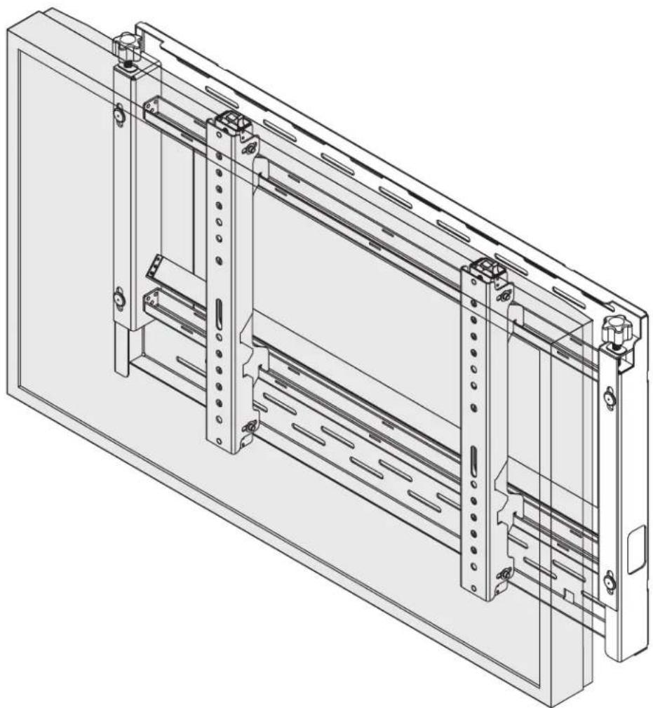
natural_image
Technical line drawing of a mechanical assembly with mounting brackets and structural supports (no text or symbols)WARNING
- Do not begin to install your Peerless product until you have read and understood the instructions and warnings contained in this Installation Sheet. If you have any questions regarding any of the instructions or warnings, for US customers please call Peerless customer care at 1-800-865-2112, for all international customers, please contact your local distributor.
- This product should only be installed by someone of good mechanical aptitude, has experience with basic building construction, and fully understands these instructions.
- Make sure that the supporting surface will safely support the combined load of the equipment and all attached hardware and components.
• Never exceed the Maximum Load Capacity. See page one. - If mounting to wood wall studs, make sure that mounting screws are anchored into the center of the studs. Use of an "edge to edge" stud finder is highly recommended.
• Always use an assistant or mechanical lifting equipment to safely lift and position equipment. - Tighten screws firmly, but do not overtighten. Overtightening can damage the items, greatly reducing their holding power.
- This product is intended for indoor use only. Use of this product outdoors could lead to product failure and personal injury.
• This product was designed to be installed on the following wall construction only;
WALL CONSTRUCTION HARDWARE REQUIRED
- Wood
Stud
Included
- Wood Beam
Included
- Solid Concrete
Included
- Cinder Block
Included
- Metal Stud
Contact Qualified Professional
- Brick
Contact Qualified Professional
- Other or unsure?
Contact Qualified Professional
Tools Needed for Assembly
- stud finder ("edge to edge" stud finder is recommended)
• phillips screwdriver - drill
- 5/16" (8 mm) bit for concrete and cinder block wall
• 5/32" (4 mm) bit for wood stud wall - level
Accessories
Horizontal and Vertical Video Wall Mount Assembly Formula....3
Parts List....4
Installation to Wood Stud Wall....5
Installation to Solid Concrete or Cinder Block....6
Installing Adapter Brackets....7
Horizontal Adjustment and Locking Adapter Brackets....8
Carriage Assembly Adjustment 9
Adapter Bracket Adjustment....10
Vertical Spacing Location - Locating the position of the bottom row of fasteners
If DS-VWS0## Wall Plate Spacer Kit is not available use diagram below to determine vertical spacing.
To determine lower mounting slot position of second mount, add display height to (Y1) or (Y2)
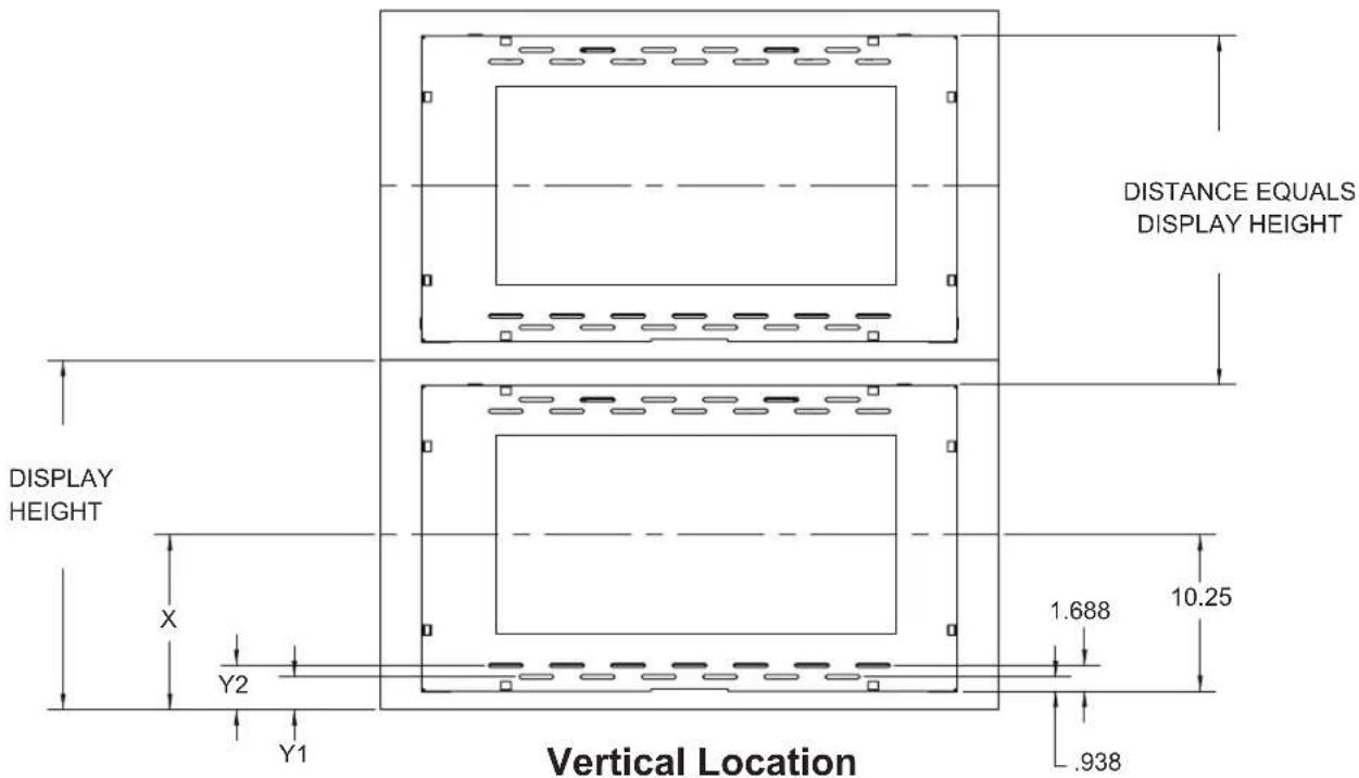
X - 10.25 + (.938 OR 1.688) = (Y1 OR Y2)
Horizontal Spacing Location
If DS-VWS0## Wall Plate Spacer Kit is not available use diagram below to determine horizontal spacing.
To determine edge of second mount, add (Z) to edge of first mount.
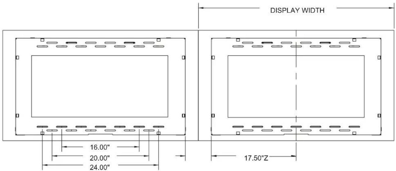
Horizontal Location
DISPLAY WIDTH - (35) = Z (SPACING BETWEEN MOUNTS)
Parts List
DescriptionQty.Part #
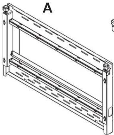
Amount assembly 1 145-T1577
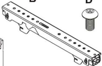
B adapter bracket 2 145-T1578
C mesh sleeve (not shown) 1 600-1014
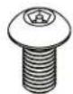
D M5 x 10 mm socket pin type-F screw 2 520-1164
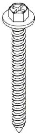
E #14 x 2.5" hex head wood screw 4 5S1-015-C03
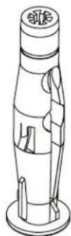
F concrete anchor 4 590-0320
G fender washer 4 540-1008
H nylon shoulder washer 4 590-2233
I M6 x 12 mm socket pin screw 4 520-1050
J M8 x 15 mm socket pin screw 4 520-1068
K 4 mm allen wrench 1 560-9646
L cable tie (not shown) 2 560-9711
M M4 x 8 mm socket pin serrated washer head screw 4 510-1005
natural_image
Technical line drawing of a multi-tiered metal frame structure (no text or symbols)B
natural_image
Technical line drawing of a mechanical component with mounting holes and a screw (no text or symbols)D
E
natural_image
Line drawing of a screw with a hexagonal head and threaded shaft (no text or symbols)F
GHI
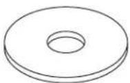
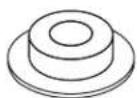
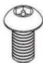
J
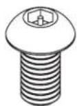
K
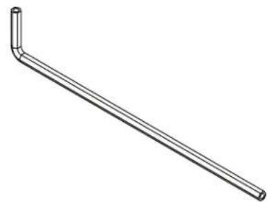
natural_image
Simple line drawing of a bent pipe or rod (no text or symbols)M

Installation to Wall Stud
⚠ WARNING
• Installer must verify that the supporting surface will safely support the combined load of the equipment and all attached hardware and components.
- Tighten wood screws so that wall plate is firmly attached, but do not overtighten. Overtightening can damage the screws, greatly reducing their holding power.
• Never tighten in excess of 80 in. • Ib (9 N.M.).
- Make sure that mounting screws are anchored into the center of the stud. The use of an "edge to edge" stud finder is highly recommended.
- Hardware provided is for attachment of mount through standard thickness drywall or plaster into wood studs. Installers are responsible to provide hardware for other types of mounting situations.

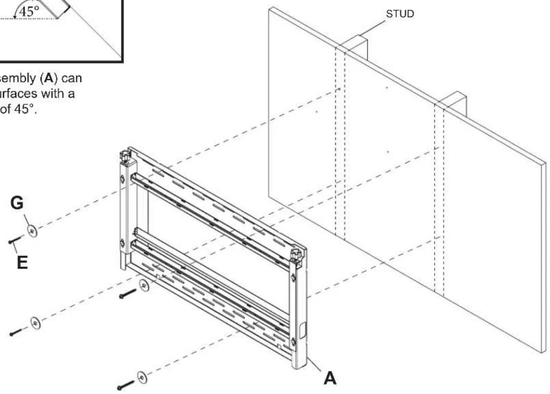
Use a stud finder to locate the edges of the stud. Use of an edge-to-edge stud finder is highly recommended. Based on their edges, draw a vertical line down the stud center. Place mount assembly (A) on wall as a template. Level plate, and mark the center of the four mounting holes. Make sure that the mounting holes are on the stud center line. Drill four 5/32" (4 mm) dia. holes 2-1/2" (65 mm) deep. Make sure that the mount assembly (A) is level, secure it using four #14 x 2.5" wood screws (E) and fender washers (G) as shown below.
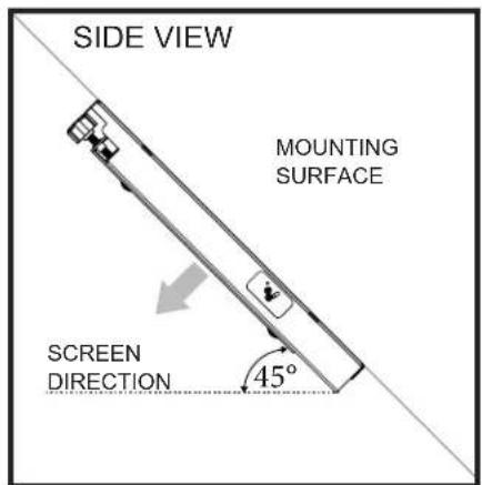
Note: Mount assembly (A) can be installed to surfaces with a maximum angle of 45^ .
Installation to Solid Concrete or Cinder Block
WARNING
- When installing Peerless wall mounts on cinder block, verify that you have a minimum of 1-3/8" (35 mm) of actual concrete thickness in the hole to be used for the concrete anchors. Do not drill into mortar joints! Be sure to mount in a solid part of the block, generally 1" (25 mm) minimum from the side of the block. Cinder block must meet ASTM C-90 specifications. It is suggested that a standard electric drill on slow setting is used to drill the hole instead of a hammer drill to avoid breaking out the back of the hole when entering a void or cavity.
• Concrete must be 2000 psi density minimum. Lighter density concrete may not hold concrete anchor. - Make sure that the wall will safely support four times the combined load of the equipment and all attached hardware and components.

Make sure that video mount assembly (A) is level, use it as a template to mark four mounting holes. Drill four 5/16" (8 mm) dia. holes to a minimum depth of 2.5" (64 mm). Insert anchors (F) in holes flush with wall as shown (right). Place video wall mount assembly over anchors and secure with four #14 x 2.5" wood screws (E) and fender washers (G) as shown below. Level, then tighten all fasteners.
WARNING
- Tighten screws so that wall plate is firmly attached, but do not overtighten. Overtightening can damage screws, greatly reducing their holding power.
• Never tighten in excess of 80 in. • lb (9 N.M.). - Always attach concrete expansion anchors directly to load-bearing concrete.
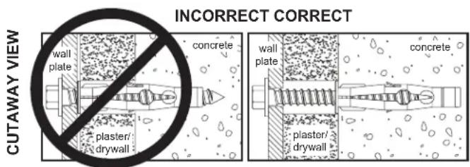
- Never attach concrete expansion anchors to concrete covered with plaster, drywall, or other finishing material. If mounting to concrete surfaces covered with a finishing surface is unavoidable, the finishing surface must be counterbored as shown below. Be sure concrete anchors do not pull away from concrete when tightening screws. If plaster/drywall is thicker than 5/8" (16 mm), custom fasteners must be supplied by installer
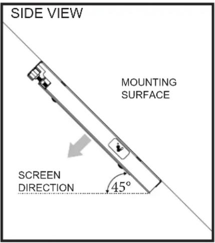
Note: Mount assembly (A) can be installed to surfaces with a maximum angle of 45^ .
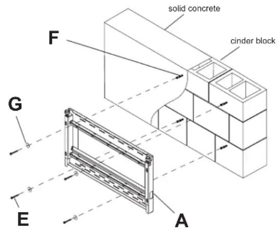
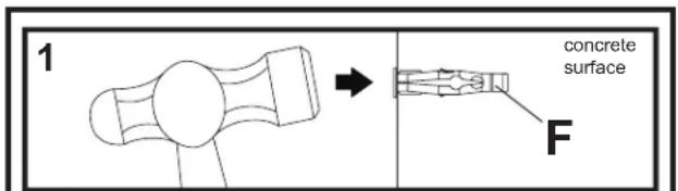
Drill holes and insert anchors (F).
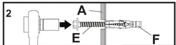
Place mount assembly (A) over anchors (F) and secure with screws (E).
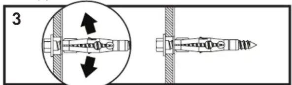
Tighten all fasteners.
Attaching Adapter Brackets to Display

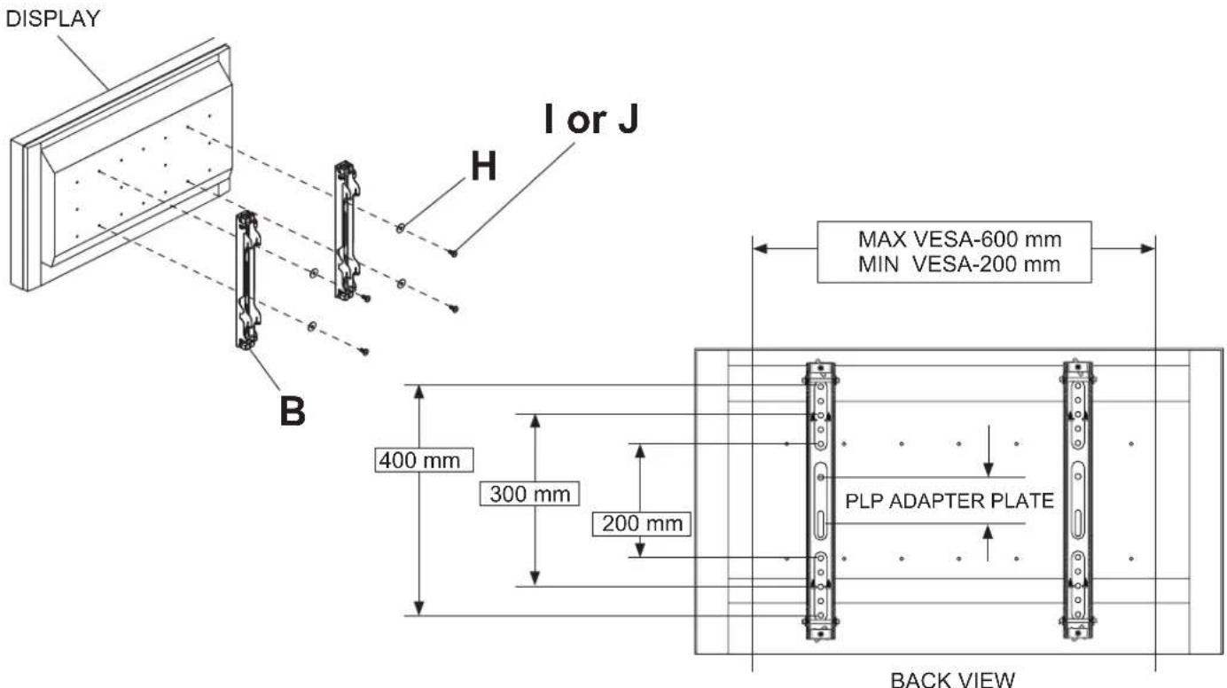
Attach adapter brackets (B) to back of display using four M6 x 12 mm socket pin screws (I) with nylon shoulder washer (H), or four M8 x 15 mm socket pin screws (J) as shown below.
NOTE: Hardware to attach dedicated plates to the mount are included with the dedicated plates.

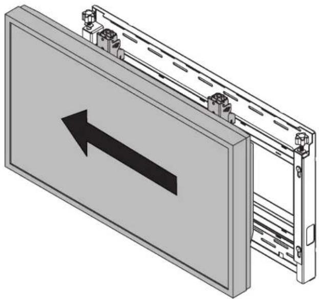
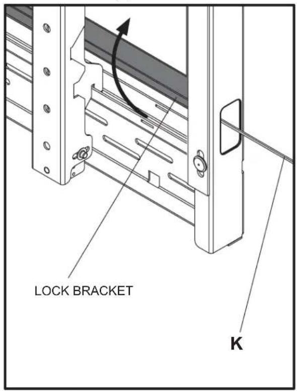
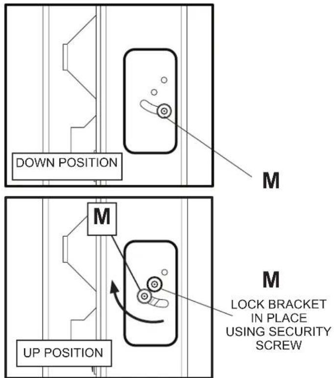
Attach adapter brackets (B) and display onto channels on carriage assembly (A) as shown in figure 3.1. Rotate lock bracket as shown in detail 1. Fasten one M4 x 8 mm socket pin serrated washer head screw (M) into slot on mount assembly (A).
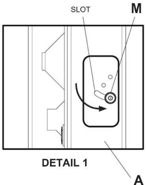
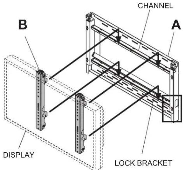
FIGURE 3.1

Horizontal Display Adjustment
Adapter Brackets (B) and display can be adjusted horizontally.
natural_image
Technical illustration of a mechanical assembly with an arrow indicating direction (no text or symbols present)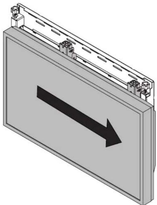
natural_image
3D diagram of a rectangular electronic device with a black arrow pointing left, mounted on a gray base (no text or symbols)
Lock Display in Place
Once Adapter Brackets (B) are in desired position, secure adapter brackets (B) using lock bracket as show below. Loosen M4 x 8 mm socket pin serrated washer head screw (M) in slot on mount assembly (A) and rotate lock bracket forward and up as shown in detail 2. Secure in up position using two M4 x 8 mm socket pin serrated washer head screw (M).
SIDE VIEW
Carriage Assembly Adjustment

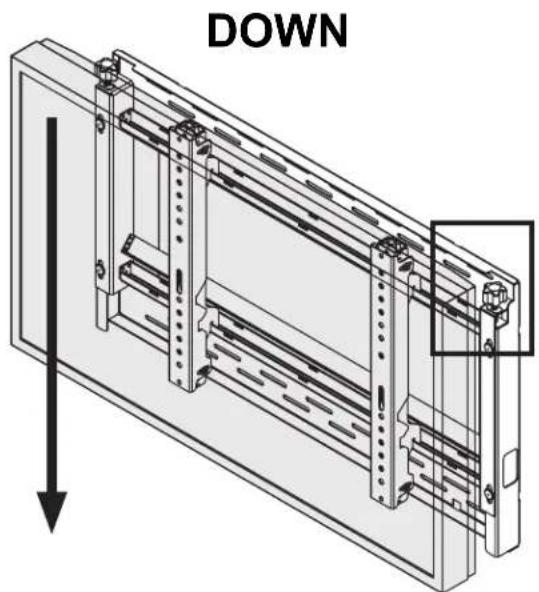
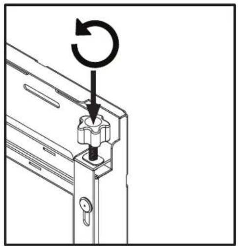
Use legend below to determine position of display.
NOTE: Each knob can be adjusted independently for fine tuning adjustments.

Turn knob CLOCKWISE to tighten

Turn knob COUNTER-CLOCKWISE to loosen
natural_image
Technical diagram showing a mechanical assembly with a rotating component and a circular arrow indicating rotation (no text or symbols present)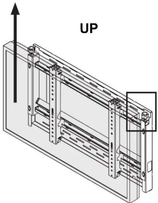
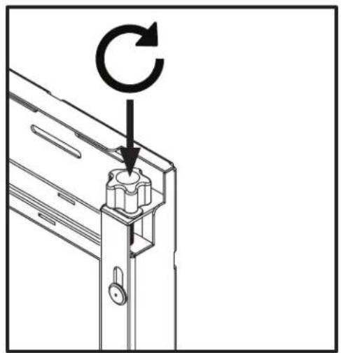
Turn knob COUNTER-CLOCKWISE to move corner up
Carriage Assembly Adjustment

Use legend below to determine position of display.
NOTE: Each knob can be adjusted independently for fine tuning adjustments.

Turn knob CLOCKWISE to tighten

Turn knob COUNTER-CLOCKWISE to loosen
IN
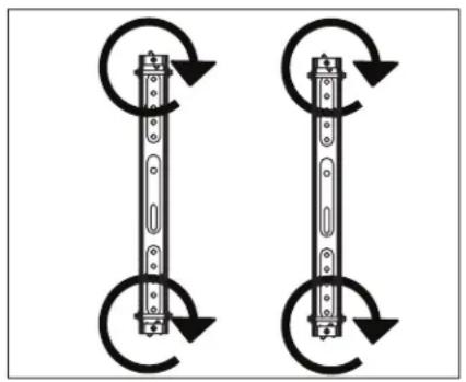
natural_image
Two identical mechanical components with circular arrows indicating rotational motion (no text or symbols)OUT
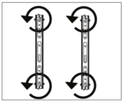
natural_image
Two identical mechanical components with circular arrows indicating rotational motion (no text or symbols)TILT FORWARD
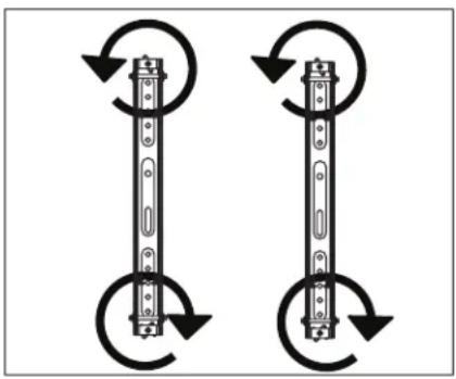
natural_image
Two identical mechanical components with circular arrows indicating rotational motion (no text or symbols)TILT BACKWARD TILT RIGHT TILT LEFT
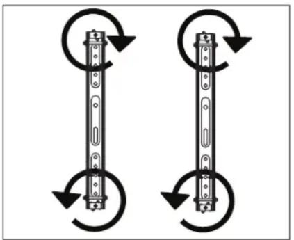
natural_image
Pure mechanical diagram showing two vertical components with circular arrows indicating rotational motion (no text or symbols)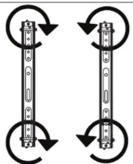
natural_image
Pure diagram of two vertical mechanical components with circular arrows indicating rotation or clockwise motion (no text or symbols)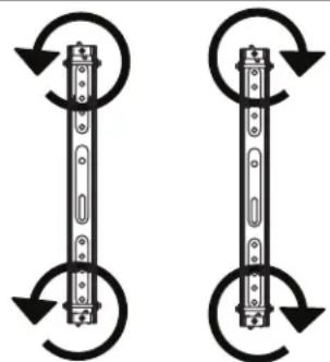
natural_image
Pure mechanical diagram showing two vertical components with circular arrows indicating rotation or clockwise motion (no text or symbols)- Installation and Assembly:
- Flat Video Wall Mount
- For 40" to 65" Flat Panel Displays
- WARNING
- WALL CONSTRUCTION HARDWARE REQUIRED
- Tools Needed for Assembly
- Accessories
- Vertical Spacing Location - Locating the position of the bottom row of fasteners
- Horizontal Spacing Location
- Parts List
- DescriptionQty.Part #
- Installation to Wall Stud
- ⚠ WARNING
- Installation to Solid Concrete or Cinder Block
- Attaching Adapter Brackets to Display
- Horizontal Display Adjustment
- Lock Display in Place
- Carriage Assembly Adjustment
Brand : NEC
Model : 100013263
Category : Support pour écran plat