
W32-70 - Support pour écran plat NEC - Free user manual and instructions
Find the device manual for free W32-70 NEC in PDF.


| Type | Tilting Wall Mount for Flat Panel Screens |
| Brand | NEC |
| Model | W32-70 |
| Maximum Weight Capacity | 100 kg (220 lbs) |
| Orientation Support | Landscape and Portrait |
| Screen Plate Fixings | Includes universal screen fixing kit with M6 screws (various lengths) |
| Wall Plate Fixings | Wall plate with multiple slots; screws not included (use appropriate masonry fixings) |
| Depth Positions | Two positions (A and B) for adjusting distance from wall; Position A closer, Position B for larger tilting screens |
| Installation | Requires qualified tradesperson; structure must support 5x weight of equipment |
| Safety Warning | Watch for pinch points; do not put fingers between moving parts |
| Parts Included | Wall Plate (A), Screen Plate (B), 4 x M10x25 hex head screws (for securing screen plate to wall plate), universal screen fixing kit |
| Compatible Screens | Designed for various NEC LCD models (e.g., M401, P401, X461HB, M461, P461, X461UN, P521) and other screens with compatible VESA patterns |
| Material | Steel (inferred from description) |
| Color | Black (inferred from exterior view description) |
| Installation Steps | 1. Attach wall plate to wall; 2. Attach screen plate to screen; 3. Hook screen onto wall plate; 4. Secure and adjust tilt |
| Tilt Adjustment | Yes, via loosening/tightening side screws |
| Support Contact | Europe: +49 (0) 9131 9405 800 / info@unicol.de; UK: +44 (0) 1865 767676 / enquiries@unicol.com |
Frequently Asked Questions - W32-70 NEC
User questions about W32-70 NEC
0 question about this device. Answer the ones you know or ask your own.
Ask a new question about this device
Download the instructions for your Support pour écran plat in PDF format for free! Find your manual W32-70 - NEC and take your electronic device back in hand. On this page are published all the documents necessary for the use of your device. W32-70 by NEC.
USER MANUAL W32-70 NEC
natural_image
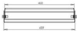
Exterior view of a black industrial enclosure with a central U-shaped component and mounting holes (no text or symbols visible)W32-70 Tilting Wall Mount
For mounting screens both in Landscape and Portrait
INSPECT THE UNIT BEFORE INSTALLING
WARNING: Watch for pinch points. Do not put your fingers between movable parts.
- Carefully inspect the Mount for shipping damage. If any damage is apparent, call your carrier claims agent and do not continue with the installation until the carrier has reviewed the damage.
NOTE: Read all instructions before starting the installation.
- Lay out components to ensure you have the required parts before proceeding (see Parts List below).
CAUTION: To prevent damage to the mount, study all instructions and illustrations before you begin the installation. Failure to do so could render the Warranty for the mount and the equipment that attaches to it null and void. Pay particular attention to the "Warnings" displayed in these Instructions.
WARNING: The W32-70 wall mount is designed to be only installed onto walls.
The maximum weight to be installed on the W32-70 wall mount is 100 Kg (220 Lbs)
Parts List:
Screws to fix mount to wall are not included.
We have supplied a Universal Screen Fixing Kit with this mount.
Consult the table in Step 2 for the correct number and size of fixings for your screen.
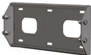
Wall Plate (A)
natural_image
Metallic rectangular component with two recessed slots and mounting holes (no text or symbols)Each Wall Plate has 4 x M10 x 25 Hex head screws (2 at each side) for securing Screen Plate.
Universal Screen Fixing Kit contains:
4 x M6 x 12 pozi pan head screws
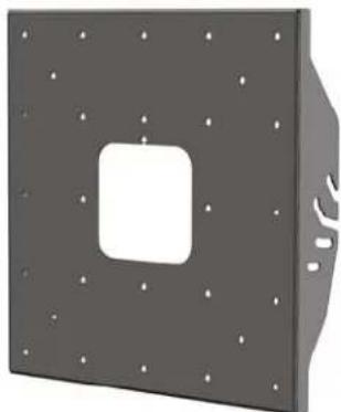
Screen Plate (B)
natural_image
3D rendering of a gray metal panel with a central square cutout and mounting holes (no text or symbols)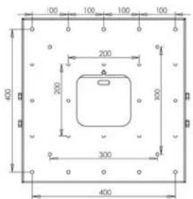
Screen Plate
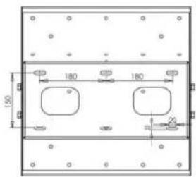
Back Plate
Bottom
1
INSTALLING BACK PLATE (A)
- Determine the exact mounting location on the wall prior to installation. Consider where the cables are routed from the wall in relation to the holes in the back plate.
WARNING: Improper installation can result in serious personal injury. Make sure that the structure can support a redundant weight factor five times the total weight of the equipment: if not, reinforce the structure before installing the mount.
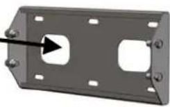
- Using the Wall Plate (A) as a template, mark, drill and plug wall using all fixing slots, fix the Wall Plate to the wall ensuring that the Plate is level.
CAUTION: We recommend installation by a Qualified Tradesperson, using masonry plugs or other reliable fixings to ensure safe installation. Consult your builder or architect if in doubt.
2
INSTALLING SCREEN PLATE (B)
Fix the Screen Plate (B) to the screen using the fixing screws provided for your screen: Ensure the flat side of the plate is against the screen and the plate is centred on the fixing points.
| LCD model | Fixing | LCD model | Fixing | LCD model | Fixing |
| M401 | M6 x 4 | P401 | M6 x 4 | X461HB | M6 x 4 |
| M461 | M6 x 4 | P461 | M6 x 4 | X461UN | M6 x 4 |
| P521 | M6 x 4 |
3
SCREEN POSITIONS
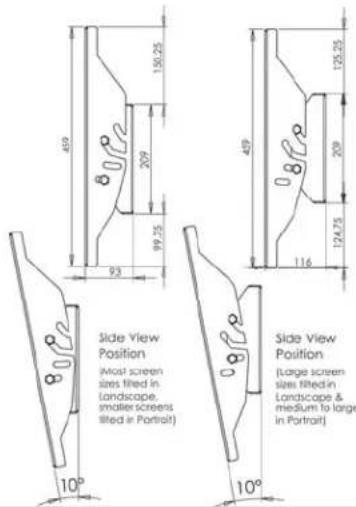
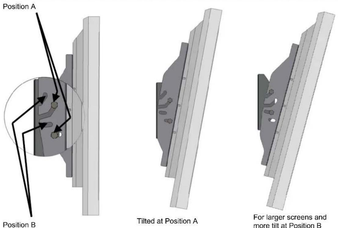
There are 2 positions that the Screen Plate can mount to the Wall Plate; See next page. Position B places the screen further from the wall than Position A, allowing larger screens enough room from the wall to be able to tilt. In general Position A (closest the wall) can be used for most screen sizes other than a tilting 65" - 70" screen. However, if more tilt is required then Position B can be used.
4
INSTALLING SCREEN ONTO WALL PLATE
WARNING: Screens are heavy. We recommend 2 persons lift the Screen when fitting to the Wall Plate.
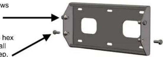
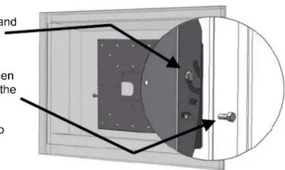
- Loosen the top 2 x M10 x 25 hex head screws located in either side of the Wall Plate by approximately 5mm.
- Remove the remaining bottom 2 x M10 x 25 hex head screws located in the sides of the Wall Plate and keep available for use in next step.
- With the assistance of another person, lift the screen complete with Screen Plate attached and hook onto the top 2 Hex head screws on the sides of the wall plate.
- Allow the screws to take the weight of the screen and refit the bottom screws. Tighten these to the desired tilt position and re-tighten top screws.
- Connect and secure power/audio/video cable to complete the installation.
If you have any questions regarding these instructions please contact UNICOL:
Europe: +49 (0) 9131 9405 800, info@unicol.de
UK: +44 (0) 1865 767676, enquiries@unicol.com
Brand : NEC
Model : W32-70
Category : Support pour écran plat