
DV-1304-A - Video Surveillance IDIS - Free user manual and instructions
Find the device manual for free DV-1304-A IDIS in PDF.


| Product Type | AI in the Box (Video Analytics Device) |
| Brand | IDIS |
| Model | DV-1304-A |
| Video Inputs | 4-Channel IP Camera (H.264/H.265) |
| Analytics Functions | Object Detection, Intrusion, Loitering, Line Crossing, Face Detection |
| Supported Protocols | DirectIP |
| Connectivity | 1x PoE In (Network + Power), 1x PoE Out (Camera), 1x DC48V Input |
| Power Supply | PoE IEEE 802.3at (Class 4, 25W) or DC 48V Adapter |
| Power Consumption | 38.4W (PoE), 48V DC 0.8A |
| Dimensions (W x H x D) | 200 mm x 44 mm x 157.6 mm (7.9" x 1.7" x 6.2") |
| Weight | 0.88 kg (1.94 lb) |
| Operating Temperature | 0°C to 40°C (32°F to 104°F) |
| Operating Humidity | 0% to 90% |
| Certification | KC, FCC, CE |
| Included Accessories | AI Box, User Guide, Rubber Feet (4 pcs) |
| Cleaning | Unplug before cleaning; use a damp soft cloth; no liquid or aerosol cleaners |
| Safety | No user-serviceable parts; refer servicing to qualified personnel; use only manufacturer-approved parts |
| Reset Button | Factory reset via pinhole switch on front panel |
| LED Indicators | Power (status), Network (connection) |
| Firmware Upgrade | Via NVR or IDIS Discovery program (USB or NetFS) |
Frequently Asked Questions - DV-1304-A IDIS
User questions about DV-1304-A IDIS
0 question about this device. Answer the ones you know or ask your own.
Ask a new question about this device
Download the instructions for your Video Surveillance in PDF format for free! Find your manual DV-1304-A - IDIS and take your electronic device back in hand. On this page are published all the documents necessary for the use of your device. DV-1304-A by IDIS.
USER MANUAL DV-1304-A IDIS
This operation manual contains basic instructions on installing and using DirectIP AI in the Box, an IDIS product. Users who are using this product for the first time, as well as users with experience using comparable products, must read this operation manual carefully before use and heed to the warnings and precautions contained herein while using the product. Safety warnings and precautions contained in this operation manual are intended to promote proper use of the product and thereby prevent accidents and property damage and must be followed at all times. Once you have read this operation manual, keep it at an easily accessible location for future reference.

- The manufacturer will not be held responsible for any product damage resulting from the use of unauthorized parts and accessories or from the user's failure to comply with the instructions contained in this operation manual.
- It is recommended that first-time users of this network camera and individuals who are not familiar with its use seek technical assistance from their retailer regarding product installation and use.
- If you need to disassemble the product for functionality expansion or repair purposes, you must contact your retailer and seek professional assistance.
- Both retailers and users should be aware that this product has been certified as being electromagnetically compatible for commercial use. If you have sold or purchased this product unintentionally, please replace with a consumer version.
Safety Precautions

CAUTION
RISK OF ELECTRIC SHOCK DO NOT OPEN

CAUTION: TO REDUCE THE RISK OF ELECTRIC SHOCK, DO NOT REMOVE COVER (OR BACK). NO USER-SERVICEABLE PARTS INSIDE. REFER SERVICING TO QUALIFIED SERVICE PERSONNEL.

The lightning flash with arrowhead symbol, within an equilateral triangle, is intended to alert the user to the presence of uninsulated "dangerous voltage" within the product's enclosure that may be of sufficient magnitude to constitute a risk of electric shock.

The exclamation point within an equilateral triangle is intended to alert the user to the presence of important operating and maintenance (servicing) instructions in the literature accompanying the appliance.
Important Safeguards
- Read Instructions All the safety and operating instructions should be read before the appliance is operated.
- Retain Instructions The safety and operating instructions should be retained for future reference.
- Cleaning Unplug this equipment from the wall outlet before cleaning it. Do not use liquid aerosol cleaners. Use a damp soft cloth for cleaning.
- Attachments Never add any attachments and/or equipment without the approval of the manufacturer as such additions may result in the risk of fire, electric shock or other personal injury.
- Water and/or Moisture Do not use this equipment near water or in contact with water.
- Ventilation Place this equipment only in an upright position. This equipment has an open-frame Switching Mode Power Supply (SMPS), which can cause a fire or electric shock if anything is inserted through the ventilation holes on the side of the equipment.
- Accessories Do not place this equipment on an wall or ceiling that is not strong enough to sustain the camera. The equipment may fall, causing serious injury to a child or adult, and serious damage to the equipment. Wall or shelf mounting should follow the manufacturer's instructions, and should use a mounting kit approved by the manufacturer.

This equipment and cart combination should be moved with care. Quick stops, excessive force, and uneven surfaces may cause the equipment and cart combination to overturn.
- Power Sources This equipment should be operated only from the type of power source indicated on the marking label. If you are not sure of the type of power, please consult your equipment dealer or local power company. You may want to install a UPS (Uninterruptible Power Supply) system for safe operation in order to prevent damage caused by an unexpected power stoppage. Any questions concerning UPS, consult your UPS retailer.
- Power Cord Operator or installer must remove power and TNT connections before handling the equipment.
- Lightning For added protection for this equipment during a lightning storm, or when it is left unattended and unused for long periods of time, unplug it from the wall outlet and disconnect the antenna or cable system. This will prevent damage to the equipment due to lightning and power-line surges. If thunder or lightning is common where the equipment is installed, use a surge protection device.
- Overloading Do not overload wall outlets and extension cords as this can result in the risk of fire or electric shock.
- Objects and Liquids Never push objects of any kind through openings of this equipment as they may touch dangerous voltage points or short out parts that could result in a fire or electric shock. Never spill liquid of any kind on the equipment.
- Servicing Do not attempt to service this equipment yourself. Refer all servicing to qualified service personnel.
14. Damage requiring Service
Unplug this equipment from the wall outlet and refer servicing to qualified service personnel under the following conditions:
A. When the power-supply cord or the plug has been damaged.
B. If liquid is spilled, or objects have hit the equipment.
C. If the equipment has been exposed to rain or water.
D. If the equipment does not operate normally by following the operating instructions, adjust only those controls that are covered by the operating instructions as an improper adjustment of other controls may result in damage and will often require extensive work by a qualified technician to restore the equipment to its normal operation.
E. If the equipment has been dropped, or the cabinet damaged.
F. When the equipment exhibits a distinct change in performance — this indicates a need for service.
15. Replacement Parts
When replacement parts are required, be sure the service technician has used replacement parts specified by the manufacturer or that have the same characteristics as the original part. Unauthorized substitutions may result in fire, electric shock or other hazards.
16. Safety Check
Upon completion of any service or repairs to this equipment, ask the service technician to perform safety checks to determine that the equipment is in proper operating condition.
17. Field Installation
This installation should be made by a qualified service person and should conform to all local codes.
18. Correct Batteries
Warning: Risk of explosion if battery is replaced by an incorrect type. Replace only with the same or equivalent type. Dispose of used batteries according to the instructions. The battery shall not be exposed to excessive heat such as sunshine, fire or the like.
19. Tmra
A manufacturer's maximum recommended ambient temperature (Tmra) for the equipment must be specified so that the customer and installer may determine a suitable maximum operating environment for the equipment.
20. Elevated Operating Ambient Temperature
If installed in a closed or multi-unit rack assembly, the operating ambient temperature of the rack environment may be greater than room ambient. Therefore, consideration should be given to installing the equipment in an environment compatible with the manufacturer's maximum rated ambient temperature (Tmra).
21. Reduced Air Flow
Installation of the equipment in the rack should be such that the amount of airflow required for safe operation of the equipment is not compromised.
22. Mechanical Loading
Mounting of the equipment in the rack should be such that a hazardous condition is not caused by uneven mechanical loading.
23. Circuit Overloading
Consideration should be given to connection of the equipment to supply circuit and the effect that overloading of circuits might have on over current protection and supply wiring. Appropriate consideration of equipment nameplate ratings should be used when addressing this concern.
24. Reliable Earthing (Grounding)
Reliable grounding of rack mounted equipment should be maintained. Particular attention should be given to supply connections other than direct connections to the branch circuit (e.g., use of power strips).
In-Text
Symbol Type Description


Caution Important information concerning a specific function.
Note Useful information concerning a specific function.
User's Caution Statement
Caution: Any changes or modifications to the equipment not expressly approved by the party responsible for compliance could void your authority to operate the equipment.
FCC Compliance Statement
THIS EQUIPMENT HAS BEEN TESTED AND FOUND TO COMPLY WITH THE LIMITS FOR A CLASS A DIGITAL DEVICE, PURSUANT TO PART 15 OF THE FCC RULES. THESE LIMITS ARE DESIGNED TO PROVIDE REASONABLE PROTECTION AGAINST HARMFUL INTERFERENCE WHEN THE EQUIPMENT IS OPERATED IN A COMMERCIAL ENVIRONMENT. THIS EQUIPMENT GENERATES, USES, AND CAN RADIATE RADIO FREQUENCY ENERGY AND IF NOT INSTALLED AND USED IN ACCORDANCE WITH THE INSTRUCTION MANUAL, MAY CAUSE HARMFUL INTERFERENCE TO RADIO COMMUNICATIONS. OPERATION OF THIS EQUIPMENT IN A RESIDENTIAL AREA IS LIKELY TO CAUSE HARMFUL INTERFERENCE, IN WHICH CASE USERS WILL BE REQUIRED TO CORRECT THE INTERFERENCE AT THEIR OWN EXPENSE.
WARNING: CHANGES OR MODIFICATIONS NOT EXPRESSLY APPROVED BY THE PARTY RESPONSIBLE FOR COMPLIANCE COULD VOID THE USER'S AUTHORITY TO OPERATE THE EQUIPMENT. THIS CLASS OF DIGITAL APPARATUS MEETS ALL REQUIREMENTS OF THE CANADIAN INTERFERENCE CAUSING EQUIPMENT REGULATIONS.
WEEE (Waste Electrical & Electronic Equipment)
Correct Disposal of This Product
(Applicable in the European Union and other European countries with separate collection systems)

This marking shown on the product or its literature, indicates that it should not be disposed with other household wastes at the end of its working life. To prevent possible harm to the environment or human health from uncontrolled waste disposal, please separate this from other types of wastes and recycle it responsibly to promote the sustainable reuse of material resources.
Household users should contact either the retailer where they purchased this product, or their local government office, for details of where and how they can take this item for environmentally safe recycling.
Business users should contact their supplier and check the terms and conditions of the purchase contract. This product should not be mixed with other commercial wastes for disposal.
Copyright
© 2024 IDIS Co., Ltd.
IDIS Co., Ltd. reserves all rights concerning this operation manual.
Use or duplication of this manual in part or whole without the prior consent of IDIS Co., Ltd. is strictly prohibited.
Contents of this manual are subject to change without prior notice for reasons such as functionality enhancements.
Registered Trademarks
IDIS is a registered trademark of IDIS Co., Ltd.
Other company and product names are registered trademarks of their respective owners.
The information in this manual is believed to be accurate as of the date of publication even though explanations of some functions may not be included. We are not responsible for any problems resulting from the use thereof. The information contained herein is subject to change without notice. Revisions or new editions to this publication may be issued to incorporate such changes.
The software included in this product contains some Open Sources. You may obtain the complete corresponding source code from us. See the Open Source Guide on the software CD (OpenSourceGuide\OpenSourceGuide.pdf) or as a printed document included along with the User's Manual.
Covered by one or more claims of the patents listed at patentlist.accessadvance.com.
1
Part 1 – Introduction....8
Product Features 8
Accessories....12
Overview 12
Front Panel....12
Rear Panel 13
System Requirements....14
Network Setup (Alias IP) ......14
Camera Installation Guide for IDLA (IDIS Deep Learning Analytics) Features .....15
2
Part 2 - Camera Installation....15
IDLA (IDIS Deep Learning Analytics) Configuration Guide .....21
Wrong Examples ......24
Conditions That Can Trigger False Alarms....27
3
Part 3 - VA in the Box Setting via NVR....29
Camera Protocol 29
Firmware Upgrade ....29
VA Box Setup....29
VA Box 30
VA Box_Schedule....34
VA Box_Maintenance....34
4
Part 4 - Configuring IDLA Events via NVR. 35
IDLA Event Setup....35
5
Part 5 - Appendix....43
Troubleshooting ....43
Specifications 43
Product Features
This AI in the Box (Artificial Intelligent in the Box) analyzes the live video from DirectIP cameras and transmits the video over Ethernet connections. This product offers the following features:
• Video Inputs : 4-channel H.264 and H.265 IP camera
- DirectIP protocol supported
- Convenient firmware upgrades via network
- Firmware duplication and auto recovery functions to enhance system stability
- Various image analysis function such as Object Detection, Intrusion, Loitering, Line Crossing and Face Detection.
- Object Detection: Detects an object (human, cars, bikes) in the zone set by the user.
- Intrusion: Detects an object (human, cars, bikes) entering or leaving the zone in the direction set by the direction options (In, Out, In/Out)
- Loitering: Detects an object (human, cars, bikes) that stays longer than the set time.
- Line Crossing: Detects an object (human, cars, bikes) which crosses a pre-defined line in the direction set by the direction options (In, Out, In/Out)
- Face Detection: Detects a human face in the zone set by the user.
- Configuration of device settings and integrated management of multiple AI Boxes on the NVR (Network Video Recorder)

Check the following before connecting the product. (Only for the examples 1,2,3)
- Check if the Swtich's PoE power per port supports 30W.
Example 1 : Connection Diagram Using PoE Switch

Example2 : Connection Diagram Using PoE Switch
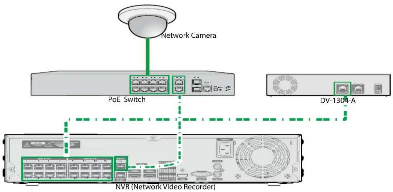
Example 3 : Connection Diagram Using PoE Switch

flowchart
graph TD
    A["Network Camera"] --> B["PoE Switch"]
    B --> C["NVR (Network Video Recorder)"]
    C --> D["DV-1304-A"]
    D --> E["VoE"]
    style A fill:#f9f,stroke:#333
    style B fill:#ccf,stroke:#333
    style C fill:#cfc,stroke:#333
    style D fill:#fcc,stroke:#333

Check the following before connecting the product. (Only for the example 4)
- Check if the NVR's PoE power per port supports 30W.
Example 4: Connection Diagram without PoE Switch

NVR (Network Video Recorder)
| Types of Cables | |
| LAN Cable (Data + PoE Power) | |
Example 5 : Sonnection Diagram without PoE Switch

| Types of Cables | |
| LAN Cable (Data + PoE Power) | |
Accessories
Upon unpacking the product, check the contents inside to ensure that all the following contents are included.
- AI in the Box
- User Guide and Instruction Manual (This document)
- Rubber Foot (4EA)
Overview
Front Panel

| 1 | Power LED | 2 | Network LED | 3 | Factory Reset Switch |
① Power LED
Displays system operating status
② Network LED
Displays network connection status
LED Status Indications
| LED Status Description | ||
| Power LED | Off No power connection | |
| Blinking System booting or upgrading | ||
| On System operating | ||
| Network LED On / Blinking Normal network connection | ||
③ Factory Reset Switch
Use to return all settings to the original factory settings. Connect the power and poke a straightened paperclip into the factory reset switch hole. Hold the reset switch until the VA Box's internal buzzer sounds twice. Release the reset switch, and all of the device settings are now at the original settings it had when it left the factory.
- Factory Reset during system booting: All of the AI Box's settings are now at the original settings it had when it left the factory.
- Factory Reset during system operating: The other settings except for system log are now at the original settings it had when it left the factory.
- Factory Reset via the IDIS Discovery program: The other settings except for system log and network settings are now at the original settings it had when it left the factory.
- Factory Reset via the IDIS Discovery program(including network settings): The other settings except for system log are now at the original settings it had when it left the factory.
Rear Panel
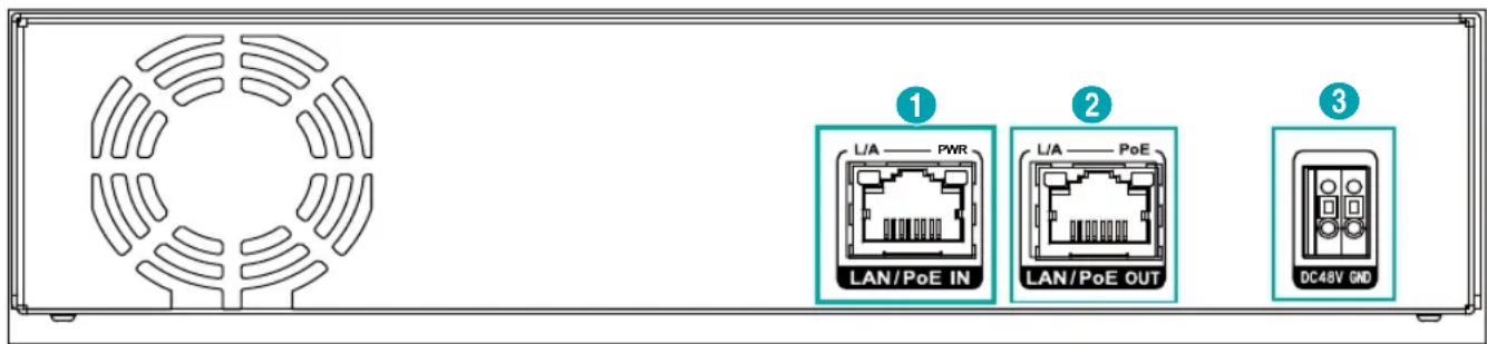
| 1 | Network + PoE Power Input | 2 | Camera + PoE Power Output | 3 | DC48V Input |
① Network + PoE Power In
Connect a Cat5e cable with an RJ-45 jack. The device is capable of connecting to networks via an Ethernet connector and also receives power (PoE) from the NVR.
② Camera + PoE Power Output
Connect a network camera. PoE power of network camera is available only when DC48V is supplied.
This product supports a camera with PoE-af (15.4 W) and a network bandwidth of 100 Mbps and does not support connecting multiple IP cameras.
③ DC48V Input
Connect the two wires of the power adapter to these ports. Be careful not to cross the DC48V and GND wires. Booting will commence once connected to a power supply.

- The network connector is not designed to be connected directly with cable or wire intended for outdoor use.

- Organize the power cable so that it will not cause people to trip over or become damaged from chairs, cabinets, desks, and other objects in the vicinity. Do not run the power cable underneath a rug or carpet.
- Do not connect multiple devices to a single power outlet.
- Please wire within 3m(118") indoors for stable power supply when installing the adapter.
Stream Setting Guide for AI Box Camera
System Requirements
• Resolution: 640x360 to 1920x1080
• IPS: 6 or higher
• Amount of Data - 640x360 @ 10ips \~ 30ips
-1280x720 @ 10ips \~ 15ips
-1920x1080@10ips

• One of the three streams must match the above conditions.
- How to calculate the amount of data : Resolution (horizontal x vertical) x ips
• Minimum Requirement
- Resolution: 640x360
- IPS: 6
- Recommended Setting
- Resolution: 640x360
- IPS: 15 or higher

- If the minimum requirements are not satisfied, analytical performance will be reduced.
- If the amount of data exceeds the maximum setting, the analysis will stop.
Network Setup (Alias IP)
1 Launch the IDIS Discovery program and then select the AI in the BOX(DV-1304-A) from the main screen whose settings you wish to change.

2 Click on the Setup icon.
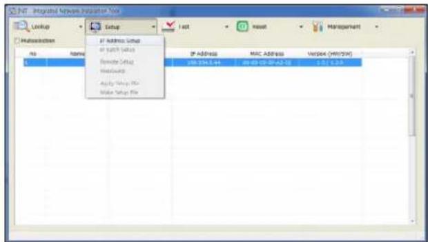
3 Select the IP Address Setup from the Setup menu to load the Alias IP setting screen. Alternatively, you can select DV-1304-A from the main screen and then right-click to access the Alias IP setting screen.


- Configure this setting before registering on NVR.
- It supports DHCP and Manual IP settings
Camera Installation Guide for IDLA (IDIS Deep Learning Analytics) Features
In order for the camera and, in effect, various AI functions to operate properly, the following must be applied.
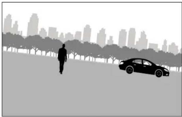
Horizontal Angel
The image should be level with the horizon. The camera should be tilted no more than 30^ from the horizontal.

natural_image
Silhouette of a person standing on a grassy field with trees and a city skyline in the background (no text or symbols)√
natural_image
Silhouette of a person walking on a tree-lined path with a car in the foreground, city skyline in background (no text or symbols)×
Object Size
To reduce the risk of missed detections, the minimum height for humans and vehicles is at least 6% of the total image height based on resolution criteria.
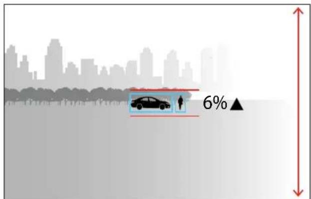
√

×

In the IDIS Center program, navigate to Menu > View > Pixel Counter.
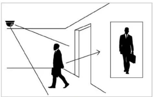
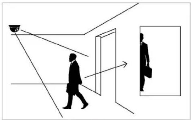
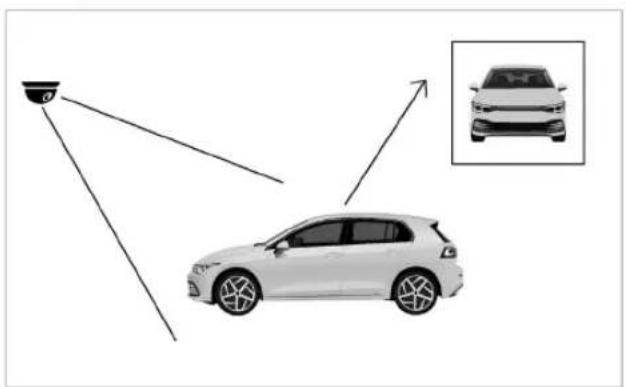
Object Visibility
Position cameras so that they can capture the entire object, such as people and vehicles in the image, rather than just a partial view.
natural_image
Silhouette of a person walking toward a glass door and window, with a magnified inset showing a man holding a briefcase (no text or symbols)√
natural_image
Silhouette of a person walking toward a window with a magnifying glass, showing an object inside (no text or symbols)×
natural_image
Diagram showing a car with sensor or detection system and an inset view of the same vehicle (no text or symbols present)√

natural_image
Diagram showing a car with sensor or detection system projecting to a vehicle, with an inset close-up of the vehicle (no text or symbols present)×
Part 2 - Camera Installation
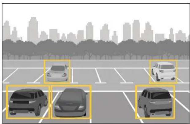
We recommend installing cameras diagonally to prevent objects from overlapping each other. (In crowded scenarios, frequent overlap can impact detection accuracy.)

natural_image
Silhouettes of two people walking on a city skyline with trees, one highlighted in yellow (no text or symbols)
natural_image
Illustration of a parking lot with five cars and trees, city skyline in background (no text or symbols)

natural_image
Silhouettes of people walking and walking through a park with city skyline in background (no text or symbols)

natural_image
Illustration of two cars with red hatched patterns on a city skyline, no text or symbols present
Face Detection
To reduce the risk of missed detections, the person's face is at least 4% of the total image height based on resolution criteria.


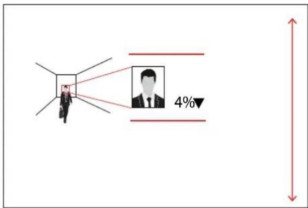


In the IDIS Center program, navigate to Menu > View > Pixel Counter.
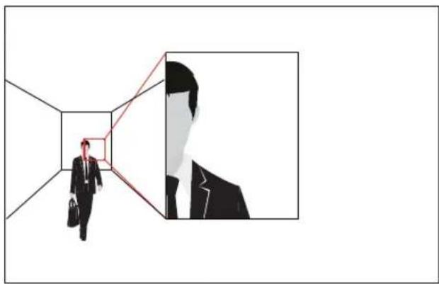
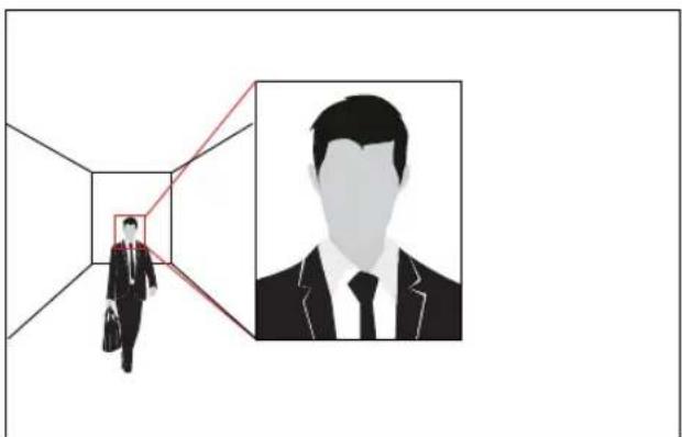
1) Mount cameras to capture the entire face in the image and position them at the average height of a person for a good angle on faces.

natural_image
Illustration of a businessman walking through a hallway with an inset portrait of a man in a suit (no text or symbols)
natural_image
Silhouette of a businessman walking through a hallway with a red line and magnified inset showing the profile (no text or symbols)
Part 2 - Camera Installation
2) Mount the camera so that person in the image is front-facing and is not looking down or up. Face detection feature recognizes within 60 degrees from horizontal and 30 degrees from vertical.


natural_image
Two identical grayscale portraits of a man in formal attire, side by side (no text or symbols)
natural_image
Silhouette of a businessman walking down a hallway with an inset portrait of a man in a suit (no text or symbols)

natural_image
Silhouette of two human figures facing each other with a vertical line dividing them (no text or symbols)
Fisheye View
Persons and vehicles must be installed at a height of at least 6% of the image height.
Fisheye lenses can produce distortion, especially near the edges of the image, which can reduce recognition accuracy.


IDLA (IDIS Deep Learning Analytics) Configuration Guide
Zone Detection
To detect an object, the user-defined detection point for the object must be within the detection zone. In the case of humans, the point is at the feet, while for vehicles, the detection point is at the bottom.

natural_image
Illustration of a white electric car on a road with a person walking nearby, no text or symbols present.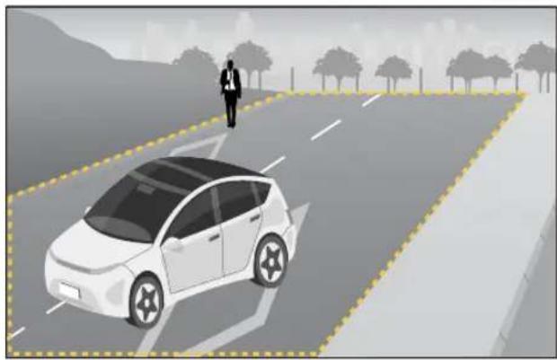
natural_image
Illustration of a white car on a road with a pedestrian walking nearby and trees in the background (no text or symbols)
Line Crossing Detection
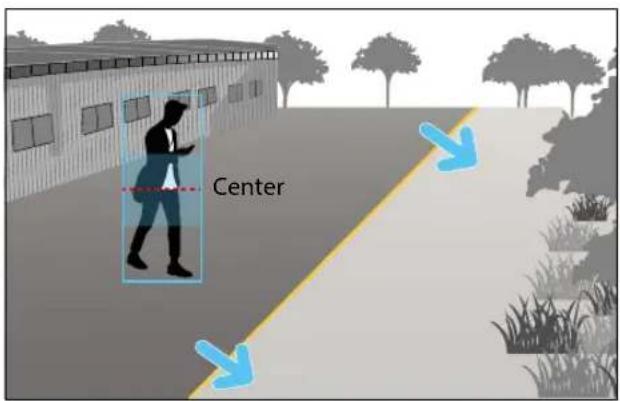
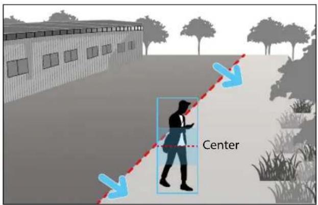
Detection occurs when the user-defined detection point for the object crosses the line.
(Line Crossing position is set to center (Center of object) by default, but you can modify it according to the installation environment in the settings)
[Pre-event] [Post-event]

Recommended Crossing Position Settings
- When the line is vertical, we recommend using the default setting.
- If the line is horizontal and the object passes through the area below the line too quickly compared to the area above the line, it is recommended to set the detection position to Lower side of object. Conversely, in the opposite scenario, setting it to Upper side of object is recommended.

natural_image
Silhouette of a person walking with a smartphone, no text or symbols presentUpper side of object
Center of object
Lower side of object
Analysis Conditions
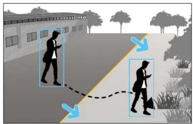
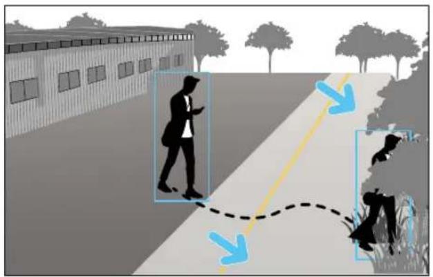
Position it in the center to capture both the before and after moments of passing the virtual line or zone.

natural_image
Illustration showing a person walking on a path with directional arrows indicating movement or interaction (no text or symbols present)

flowchart
graph TD
    A["Left Intersection"] --> B{Flow Direction}
    B --> C["Top Left"]
    B --> D["Bottom Right"]
    C --> E["Right Edge"]
    D --> F["Left Edge"]
    style A fill:#f9f,stroke:#333
    style B fill:#ccf,stroke:#333
    style C fill:#cfc,stroke:#333
    style D fill:#fcc,stroke:#333


natural_image
Aerial view of a city intersection with a parked car, showing crosswalk patterns and traffic flow (no text or symbols)
Wrong Examples
Postures Other Than Upright Position
Humans should move in a somewhat upright position.

natural_image
Silhouettes of two people walking in a park with city skyline in background (no text or symbols)

natural_image
Silhouettes of people running and playing outdoors with a city skyline in the background (no text or symbols)
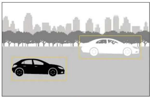
Insufficient Dissimilarity Between Objects and the Background
There should be sufficient dissimilarity between objects and the background to distinguish the object from the background or other objects. Fog, direct light shining on the camera, or an excessive noisy image can cause contrast issues. You can adjust the level of illumination and adjust the image settings to enhance the level of contrast.
natural_image
Silhouettes of two cars in front of a city skyline with trees (no text or symbols)√

natural_image
Silhouette of a city skyline with trees and a bridge in the foreground (no text or symbols)×

natural_image
Silhouette of a car parked on a road with trees and a city skyline in the background (no text or symbols)×
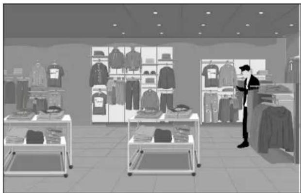
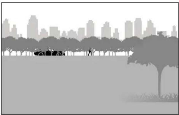
When Obstacles such as Trees, Walls, or Fences Partially Obstruct the Object

natural_image
Silhouette of a person walking on a tree-lined street with a city skyline in the background (no text or symbols)√
natural_image
Interior view of a clothing store with display shelves and a person standing near them (no visible text or signage)×
natural_image
Silhouette of a park with trees, a car, and a city skyline in the background (no text or symbols)×

natural_image
Silhouette of a person running near a chain-link fence with a car, against a city skyline background (no text or symbols)×

natural_image
Silhouette of a person standing in a doorway with city skyline in background (no text or symbols)×
When a Person Is Nearly Obscured by a Parked Vehicle
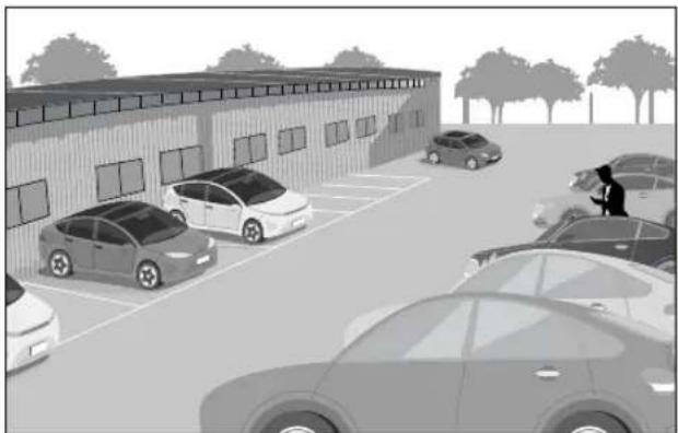
natural_image
Exterior view of a modern industrial building with parked cars and a person standing nearby (no signage or text visible)
Conditions That Can Trigger False Alarms
Environments
• Fog
• Heavy rain or snowfall
• Insects on the camera lens
• If water droplets form on the camera lens
Environments
- Inadequate brightness or light
• Overly noisy image - Direct light shining on the camera
- If the position of the camera differs from the direction of a light source and it makes a shadow.
- If an object is reflected on the floor, wall, glass, metal or water
• Strong light causing shadows. - If the mirror is reflecting light
• A combination of car headlights and intense rain
Other Conditions
- When several extremely fast moving objects appear randomly
• Human-size animals.
Part 3 - VA in the Box Setting via NVR
Configure basic VA Box settings and all other system settings.

- Screen images may vary depending on the model.
- When using the camera with Intelleigent Codec, it could delay the image analysis up to 10 seconds.

- When the MAT (Motion Adaptive Transmission) function is active, the image analysis may not work properly.
- It is recommended that you do not use the MAT function of the associated camera to increase the accuracy of the image analysis.

Camera Protocol
VA Box supports DirectIP protocol.
- DirectIP protocol:
- Using with a DirectIP NVR enables VA Box use without the need to configure network settings.
- The DirectIP NVR also allows you to control all VA Box settings directly from the NVR, without the need for a computer.

- For more information on configuring VA Box settings from a DirectIP NVR, refer to the Part 3 - VA in the Box Setting via NVR on page 29.

Firmware Upgrade
Refer to the Firmware Upgrade on page 29 to perform a firmware upgrade.
VA Box Setup
Select Device Setup-VA Box from the setup menu. Login with an ID that has permission to access the setup menu is needed to access and make changes to the Setup menu.
1 While in Live mode, press the remote control's SETUP button or select Live menu > Setup using the mouse.

2 Use the remote control's arrow buttons to select an option and then press the remote control's button or left-click on the option using the mouse.
VA Box
By analyzing camera images, you can check real-time analysis results from a client program such as the IDIS Center.


VA Box can only analyze the video from the camera using H.264 and H.265.
VA Box\_Registration
You can register VA Box at remote locales.

• Title: Edit the VA Box's name.
- MAC Address: Displays the VA Box's MAC address registered to the NVR.
- Address: Displays the VA Box's IP address registered to the NVR.
- Model: Indicates the VA Box's model.
- Scan: Select to scan and register the device connected to the NVR.
Device Scan
Scan the device under VA Box- Registration - Scan.

- No.: Select the number of the registered VA Box and click the Add Box button to register the camera.
- MAC Address: Displays the scanned device's MAC address.
- Address: Displays the scanned device's IP address.
- Model: Indicates the device model.
- Registered Device MAC Address: Displays the MAC address of the NVR to have registered VA Box.
- Status: "Registered" indicates the VA Box is registered to the NVR and "Not registered" indicates the VA Box is not registered to the NVR.
VA Box\_Setup
Configure VA Box-related settings.

• Title: Displays the name of a VA Box.
- Model: Indicates the VA Box's model.

The video analytics may not be supported depending on the model.
- Camera: Select the camera to analyze the video. Only one camera can be set for each VA Box channel.
- Set up: The settings appear differently depending on the Analytic Type. Refer to the setting items for each Analytic Type
- Reset: Resets the port or VA Box.
- PoE Reset: Control the PoE Switch's port. This option is available when connecting to Video In/PoE port or using a DirectIP PoE Switch (optional). Select PoE Reset to reboot VA Box.
- Soft Reset: Reboots VA Box.

Use a client program such as IDIS Center to check the analysis results.
• Analytic Type:
- DV-1304: Select one among People Counting, HeatMap, Social Distancing Violation, Mask Rule Violation and Queue Monitoring.
- DV-1304-A: Select one among Object Detection, Intrusion, Loitering, Line Crossing and Face Detection.
Object Detection
Object Detection technology detects an object (human, vehicle) in the zone set by the user.
Drag and drop the vertex to modify a previously set zone or click on the left mouse button to reset the zone.
![1 Zone1 [Human] Object Detection Zone Setup OK Cancel](/content/2026/05/1065181/images/2556bd90de0ce39b70c818994e8f33bab49873497352014c265c4b3a90933bd2.jpg)
Right-click on the zone setup screen to bring up the Object Detection Menu.
- Configuration: Set the environment of Object Detection. Select Object Detection as the video analysis type, and then select Settings.
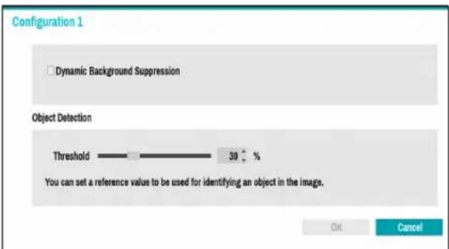
- Dynamic background suppression: Detects moving objects in video and removes the background.
- Threshold: Set a reference value that can be recognized as an object in the image.
Intrusion
Set direction options (In, Out, In/Out) to detect an object (human, vehicle) entering or leaving the zone.
Drag and drop the vertex to modify a previously set zone or click on the left mouse button to reset the zone.

Right-click on the zone setup screen to bring up the Intrusion Menu.
- Configuration: Set the environment of Intrusion. Select Intrusion as the video analysis type, and then select Settings.

- Dynamic background suppression: Detects moving objects in video and removes the background.
- Threshold : Set a reference value that can be recognized as an object in the image.
Loitering
Loitering detection technology detects an object (human, vehicle) that stays longer than the set time. Drag and drop the vertex to modify a previously set zone or click on the left mouse button to reset the zone.
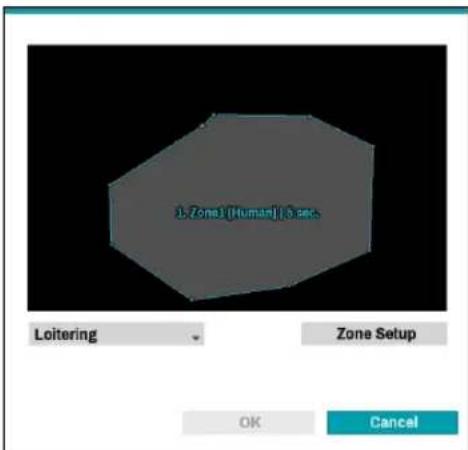
Right-click on the zone setup screen to bring up the Loitering Menu.
- Configuration : Set the environment of Loitering. Select Loitering as the video analysis type, and then select Settings.

- Dynamic background suppression: Detects moving objects in video and removes the background.
- Threshold : Set a reference value that can be recognized as an object in the image.
Part 3 - VA in the Box Setting via NVR
Line Crossing
Set direction options (In, Out, In/Out) to detect an object (human, vehicle) which crosses a pre-defined line. Click on the left mouse button to reset the line.
![1. Line1 [Ruman] B A Line Crossing Line Setup OK Cancel](/content/2026/05/1065181/images/cf15baf723d859060d71ddcdca6d485cfa941539dc53c6f7dcf7b580ec119378.jpg)
Right-click on the line setup screen to bring up the Line Crossing Menu.
- Configuration : Set the environment of Line Crossing. Select Line Crossing as the video analysis type, and then select Settings.

- Dynamic background suppression : Detects moving objects in video and removes the background. - Threshold : Set a reference value that can be recognized as an object in the image.
Face Detection
Face Detection technology analyzes faces in an image. Drag and drop the vertex to modify a previously set zone or click on the left mouse button to reset the zone

Right-click on the zone setup screen to bring up the Face Detection Menu.
- Configuration: Set the environment of Face Detection. Select Face Detection as the video analysis type, and then select Settings.
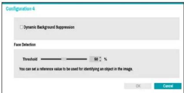
- Dynamic background suppression : Detects moving objects in video and removes the background. - Threshold : Set a reference value that can be recognized as an object in the image.
VA Box\_Schedule
Configure the schedule of the VA Box. Select the + button on the bottom left of the screen to add a schedule. Select Day to specify the Day setting or select All. Select Scope to specify the time frame.


Deleting the schedules stops the real-time video analysis.
VA Box\_Maintenance
When using NetFS, select Firmware Upgrade. You can select USB storage or NetFS. If not using NetFS, you can select USB storage only. Select USB storage to display USB search window and then select the corresponding upgrade package from the storage device connected to the NVR's USB port. After selecting an upgrade package, select Apply to upgrade the VA Box.
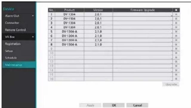

- The VA Box will reboot after the upgrade and then reconnect automatically.
Part 4 - Configuring IDLA Events via NVR
IDLA Event Setup
Select Event Setup-IDLA from the setup menu.
Login with an ID that has permission to access the setup
menu is needed to access and make changes to the
1 While in Live mode, press the remote control's SETUP button or select Live menu > Setup using the mouse.

2 Use the remote control's arrow buttons to select an option and then press the remote control's button or left-click on the option using the mouse.
IDLA (IDIS Deep Learning Analytics)
This is a list of events that occur during AI video analysis.

IDLA\_Object Detection
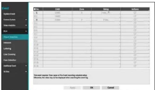
- No.: Select which cameras to apply Object Detection to. It is activated only when the analytic type is set to Object Detection in the Device - VA Box- Setup tab.
- CAM: Indicates the camera channel. VA BOX title is displayed next to the camera channel number. Refer to the VA Box_Setup on page 91 for basic information on setting the VA BOX.
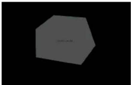
- Zone: Set a zone to be detected as a polygon.
natural_image
Simple 3D hexagonal shape with no text or symbolsYou can set a zone using the mouse. The zone is displayed in transparent. Drag and drop the vertex to modify the zone.
Right-click on the zone setup screen to bring up the Object Detection Menu.

- Zone Title: Select the zone to change the settings. When selecting the zone, a check mark appears to the left.
- Clear: Clear the selected zone.
- Undo: Remove the last point of a line.
- Edit Name: Change the name of the zone.
- Object: Select an object to detect.
- Add: Add a zone.
- Delete: Delete the selected zone.
- Delete All: Delete all zones.
- Mode: Display the modes supported by the camera.
- Preset: Select an AI PTZ camera preset.
- Save: Save the changes and exit the menu.
- Cancel : Exit the setup screen without saving the changes.

Modes and preset functions are supported only by AI PTZ cameras.
- Setup: When an event occurs, set the conditions to ignore the event and whether to use PTZ AI Tracking.

- Ignore Condition: The system does not produce event log entries or issue remote notifications regarding event for the specified time after the initial event was detected. Set the value between 1 sec and 5 secs or choose Never. Ignore Condition does not affect Object Detection recording.
- Use Ignoring Time: Object Detection function will be disabled during the specified time.
- PTZ AI Tracking: Enable PTZ AI tracking function.
- Actions: Specify which actions to take when the function is detected.
- Record: Specify which cameras to begin linked recording on when an event occurs. If the schedule is set to Event or Time & Event mode, the selected cameras will begin linked recording when an event occurs.
- Alarm-Out: Designate event-triggered alarm-out channels (each for the NVR and camera) and beeps.
- Notify: Configure to be notified of events by Mail, LAN1 through 5, Push, FTP, and/or Alert Window.
- PTZ: Moves the PTZ camera to a specific preset position when an event occurs.
- Event Monitoring: Selects the cameras to monitor when an event occurs.

• In order to use the Callback feature, the NVR must be registered on the remote program.
- When the analytic type is set to Object Detection in the Device - VA Box- Setup tab, Use Ignoring Time option is not displayed on the screen.
- The PTZ AI tracking function is displayed only on AI PTZ cameras - Setup.
• To use the IDLA function, you need to set up a time-lapse or pre-event recording schedule in advance. Otherwise, the video may not be displayed when searching the event log.
IDLA\_Intrusion

- No.: Select which cameras to apply Intrusion to. It is activated only when the analytic type is set to Intrusion in the Device - VA Box- Setup tab.
- CAM: Indicates the camera channel. VA BOX title is displayed next to the camera channel number. Refer to the VA Box_Setup on page 91 for basic information on setting the VA BOX.
- Zone: Set a zone to be detected as a polygon.

natural_image
Simple gray hexagon shape on black background (no text or symbols)You can set a zone using the mouse. The zone is displayed in transparent. Drag and drop the vertex to modify the zone.
Right-click on the zone setup screen to bring up the Intrusion Menu.

- Zone Title: Select the zone to change the settings. When selecting the zone, a check mark appears to the left.
- Clear: Clear the selected zone.
- Undo: Remove the last point of a line.
- Edit Name: Change the name of the zone.
- Object: Select an object to detect.
- Direction: Select the direction of the obejct to detect.
- Add: Add a zone.
- Delete: Delete the selected zone.
- Delete All: Delete all zones.
- Mode: Display the modes supported by the camera.
- Preset: Select an AI PTZ camera preset.
- Save: Save the changes and exit the menu.
- Cancel: Exit the setup screen without saving the changes.

Modes and preset functions are supported only by AI PTZ cameras.
- Setup: When an event occurs, set the conditions to ignore the event and whether to use PTZ AI Tracking.
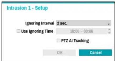
- Ignore Condition: The system does not produce event log entries or issue remote notifications regarding event for the specified time after the initial event was detected. Set the value between 1 sec and 5 secs or choose Never. Ignore Condition does not affect Intrusion recording.
- Use Ignoring Time: Intrusion function will be disabled during the specified time.
- PTZ AI Tracking: Enable PTZ AI tracking function.
- Actions: Specify which actions to take when the function is detected.
- Record: Specify which cameras to begin linked recording on when an event occurs. If the schedule is set to Event or Time & Event mode, the selected cameras will begin linked recording when an event occurs.
- Alarm-Out: Designate event-triggered alarm-out channels (each for the NVR and camera) and beeps.
- Notify: Configure to be notified of events by Mail, LAN1 through 5, Push, FTP, and/or Alert Window.
- PTZ: Moves the PTZ camera to a specific preset position when an event occurs.
- Event Monitoring: Selects the cameras to monitor when an event occurs.

• In order to use the Callback feature, the NVR must be registered on the remote program.
- When the analytic type is set to Intrusion Detection in the Device - VA Box- Setup tab, Use Ignoring Time option is not displayed on the screen.
- The PTZ AI tracking function is displayed only on AI PTZ cameras - Setup.
• To use the IDLA function, you need to set up a time-lapse or pre-event recording schedule in advance. Otherwise, the video may not be displayed when searching the event log.
IDLA\_Loitering

- No.: Select which cameras to apply Loitering to. It is activated only when the analytic type is set to Loitering in the Device - VA Box- Setup tab.
- CAM: Indicates the camera channel. VA BOX title is displayed next to the camera channel number. Refer to the VA Box_Setup on page 91 for basic information on setting the VA BOX.
- Zone: Set a zone to be detected as a polygon.

natural_image
Abstract geometric shape with a small horizontal line inside, set against a black background (no text or symbols)You can set a zone using the mouse. The zone is displayed in transparent. Drag and drop the vertex to modify the zone.
Right-click on the zone setup screen to bring up the Intrusion Menu.

- Zone Title: Select the zone to change the settings. When selecting the zone, a check mark appears to the left.
- Clear: Clear the selected zone.
- Undo: Remove the last point of a line.
- Edit Name: Change the name of the zone.
- Object: Select an object to detect.
- Activation Time: Set the time when the function is activated.
- Add: Add a zone.
- Delete: Delete the selected zone.
- Delete All: Delete all zones.
- Mode: Display the modes supported by the camera.
- Preset: Select an AI PTZ camera preset.
- Save: Save the changes and exit the menu.
- Cancel : Exit the setup screen without saving the changes.

Modes and preset functions are supported only by AI PTZ cameras.
- Setup: When an event occurs, set the conditions to ignore the event and whether to use PTZ AI Tracking.

- Ignore Condition: The system does not produce event log entries or issue remote notifications regarding event for the specified time after the initial event was detected. Set the value between 1 sec and 5 secs or choose Never. Ignore Condition does not affect Loitering recording.
- Use Ignoring Time: Loitering function will be disabled during the specified time.
- PTZ AI Tracking: Enable PTZ AI tracking function.
- Actions: Specify which actions to take when the function is detected.
- Record: Specify which cameras to begin linked recording on when an event occurs. If the schedule is set to Event or Time & Event mode, the selected cameras will begin linked recording when an event occurs.
- Alarm-Out: Designate event-triggered alarm-out channels (each for the NVR and camera) and beeps.
-
Notify: Configure to be notified of events by Mail, LAN1 through 5, Push, FTP, and/or Alert Window.
-
PTZ: Moves the PTZ camera to a specific preset position when an event occurs.
- Event Monitoring: Selects the cameras to monitor when an event occurs.

- In order to use the Callback feature, the NVR must be registered on the remote program.
- When the analytic type is set to Loitering in the Device - VA Box- Setup tab, Use Ignoring Time option is not displayed on the screen.
- The PTZ AI tracking function is displayed only on AI PTZ cameras - Setup.
- To use the IDLA function, you need to set up a time-lapse or pre-event recording schedule in advance. Otherwise, the video may not be displayed when searching the event log.
IDLA\_Line Crossing

- No.: Select which cameras to apply Line Crossing to. It is activated only when the analytic type is set to Line Crossing in the Device - VA Box- Setup tab.
- CAM: Indicates the camera channel. VA BOX title is displayed next to the camera channel number. Refer to the VA Box_Setup on page 91 for basic information on setting the VA BOX.
• Line: Set a line to be detected.

natural_image
Completely black image with no visible content or text.You can set the line using the mouse. The line is displayed in transparent.
Right-click on the line setup screen to bring up the Intrusion Menu.
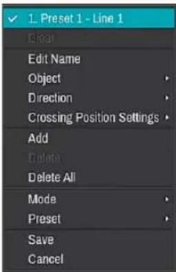
- Line Title: Select the line to change the settings. When selecting the line, a check mark appears to the left.
- Clear: Clear the selected line.
- Edit Name: Change the name of the line.
-
Object: Select an object to detect.
-
Direction: Select the direction of the obejct to detect.
- Crossing Position Settings: Set the crossing position of the object.
- Add: Add a line.
- Delete: Delete the selected line.
- Delete All: Delete all lines.
- Mode: Display the modes supported by the camera.
- Preset: Select an AI PTZ camera preset.
- Save: Save the changes and exit the menu.
- Cancel : Exit the setup screen without saving the changes.

Modes and preset functions are supported only by AI PTZ cameras.
- Setup: When an event occurs, set the conditions to ignore the event and whether to use PTZ AI Tracking.

- Ignore Condition: The system does not produce event log entries or issue remote notifications regarding event for the specified time after the initial event was detected. Set the value between 1 sec and 5 secs or choose Never. Ignore Condition does not affect Line Crossing recording.
- Use Ignoring Time: Intrusion function will be disabled during the specified time.
- PTZ AI Tracking: Enable PTZ AI tracking function.
- Actions: Specify which actions to take when the function is detected.
- Record: Specify which cameras to begin linked recording on when an event occurs. If the schedule is set to Event or Time & Event mode, the selected cameras will begin linked recording when an event occurs.
- Alarm-Out: Designate event-triggered alarm-out channels (each for the NVR and camera) and beeps.
- Notify: Configure to be notified of events by Mail, LAN1 through 5, Push, FTP, and/or Alert Window.
- PTZ: Moves the PTZ camera to a specific preset position when an event occurs.
- Event Monitoring: Selects the cameras to monitor when an event occurs.

• In order to use the Callback feature, the NVR must be registered on the remote program.
- When the analytic type is set to Line Crossing in the Device - VA Box- Setup tab, Use Ignoring Time option is not displayed on the screen.
- The PTZ AI tracking function is displayed only on AI PTZ cameras - Setup.
• To use the IDLA function, you need to set up a time-lapse or pre-event recording schedule in advance. Otherwise, the video may not be displayed when searching the event log.
IDLA\_Face Detection

- No.: Select which cameras to apply Face Detection to. It is activated only when the analytic type is set to Face Detection in the Device - VA Box- Setup tab.
- CAM: Indicates the camera channel. VA BOX title is displayed next to the camera channel number. Refer to the VA Box_Setup on page 91 for basic information on setting the VA BOX.
- Zone: Set the zone to be detected as a polygon.

natural_image
Simple geometric shape resembling a truncated octagon with a small blue triangle at center (no text or symbols)You can set a zone using the mouse. The zone is displayed in transparent. Drag and drop the vertex to modify the zone.
Right-click on the zone setup screen to bring up the Intrusion Menu.

- Zone Title: Select the zone to change the settings. When selecting the zone, a check mark appears to the left.
- Clear: Clear the selected zone.
- Undo: Remove the last point of a line.
- Edit Name: Change the name of the zone.
- Add: Add a zone.
- Delete: Delete the selected zone.
- Delete All: Delete all zones.
- Mode: Display the modes supported by the camera.
- Preset: Select an AI PTZ camera preset.
- Save: Save the changes and exit the menu.
- Cancel : Exit the setup screen without saving the changes.

Modes and preset functions are supported only by AI PTZ cameras.
- Setup: When an event occurs, set the conditions to ignore the event and whether to use PTZ AI Tracking.
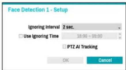
- Ignore Condition: The system does not produce event log entries or issue remote notifications regarding event for the specified time after the initial event was detected. Set the value between 1 sec and 5 secs or choose Never. Ignore Condition does not affect Face Detection recording.
- Use Ignoring Time: Face Detection function will be disabled during the specified time.
- PTZ AI Tracking: Enable PTZ AI tracking function.
- Actions: Specify which actions to take when the function is detected.
- Record: Specify which cameras to begin linked
recording on when an event occurs. If the schedule is set to Event or Time & Event mode, the selected cameras will begin linked recording when an event occurs.
- Alarm-Out: Designate event-triggered alarm-out channels (each for the NVR and camera) and beeps.
- Notify: Configure to be notified of events by Mail, LAN1 through 5, Push, FTP, and/or Alert Window.
- PTZ: Moves the PTZ camera to a specific preset position when an event occurs.
- Event Monitoring: Selects the cameras to monitor when an event occurs.

- In order to use the Callback feature, the NVR must be registered on the remote program.
- When the analytic type is set to Face Detection in the Device - VA Box- Setup tab, Use Ignoring Time option is not displayed on the screen.
- The PTZ AI tracking function is displayed only on AI PTZ cameras - Setup.
- To use the IDLA function, you need to set up a time-lapse or pre-event recording schedule in advance. Otherwise, the video may not be displayed when searching the event log.
Troubleshooting
| Problem Check | |
| Power LED will not turn on | • Check the LAN cable.• Check that the power cable is connected or the NVR has power. |
| The system is unable to recognize network interface | • Check the LAN cable.• Check the network LED. |
Specifications
| Model DV-1304-A | ||
| Video | Input 4ch IP | |
| Compression H.264 / H.265 | ||
| Input/Output | Ethernet PoE In/Out Port : 10 Mbps / 100Mbps | |
| DC48V Input Terminal Blocks | ||
| LED Power(Status), Network | ||
| Button/Switch Reset | ||
| Environmental Conditions | Operating Temperature 32°F to 104°F (0°C ~ 40°C) | |
| Operating Humidity 0% ~ 90% | ||
| General | Dimensions (W x H x D) 200mm x 44mm x 157.6mm (7.9" x 1.7" x 6.2") | |
| Unit Weight | 0.88kg (1.94 lb) | |
| Power Supply | 48V... PoE | |
| Power Input | ADAPTOR (INPUT : 100-240V~, 50/60Hz, 1.2A, OUTPUT : 48V ..., 1.0A) | |
| Power Consumption | 48V..., 0.8A, 38.4W PoE, IEEE 802.3at(Class 4), 25W DC OUTPUT : 48V..., 0.35A MAX | |
| Approval | KC, FCC, CE | |

These product specifications may change without prior notice.
IDIS®
IDIS Co., Ltd.
For more information, please visit at
www.idisglobal.com
- Safety Precautions
- CAUTION
- Important Safeguards
- Damage requiring Service
- Replacement Parts
- Safety Check
- Field Installation
- Correct Batteries
- Tmra
- Elevated Operating Ambient Temperature
- Reduced Air Flow
- Mechanical Loading
- Circuit Overloading
- Reliable Earthing (Grounding)
- In-Text
- Symbol Type Description
- User's Caution Statement
- FCC Compliance Statement
- WEEE (Waste Electrical & Electronic Equipment)
- Correct Disposal of This Product
- (Applicable in the European Union and other European countries with separate collection systems)
- Copyright
- Registered Trademarks
- 1
- Part 1 – Introduction....8
- 2
- Part 2 - Camera Installation....15
- 3
- Part 3 - VA in the Box Setting via NVR....29
- 4
- Part 4 - Configuring IDLA Events via NVR. 35
- 5
- Part 5 - Appendix....43
- Product Features
- Accessories
- Overview
- Front Panel
- ① Power LED
- ② Network LED
- ③ Factory Reset Switch
- Rear Panel
- ① Network + PoE Power In
- ② Camera + PoE Power Output
- ③ DC48V Input
- Stream Setting Guide for AI Box Camera
- System Requirements
- • Minimum Requirement
- - Recommended Setting
- Network Setup (Alias IP)
- Camera Installation Guide for IDLA (IDIS Deep Learning Analytics) Features
- Horizontal Angel
- Object Size
- Object Visibility
- Part 2 - Camera Installation
- Face Detection
- Fisheye View
- IDLA (IDIS Deep Learning Analytics) Configuration Guide
- Zone Detection
- Line Crossing Detection
- Recommended Crossing Position Settings
- Analysis Conditions
- Wrong Examples
- Postures Other Than Upright Position
- Insufficient Dissimilarity Between Objects and the Background
- When Obstacles such as Trees, Walls, or Fences Partially Obstruct the Object
- When a Person Is Nearly Obscured by a Parked Vehicle
- Conditions That Can Trigger False Alarms
- Environments
- Other Conditions
- Part 3 - VA in the Box Setting via NVR
- Camera Protocol
- Firmware Upgrade
- VA Box Setup
- VA Box
- VA Box\_Registration
- Device Scan
- VA Box\_Setup
- • Analytic Type:
- Object Detection
- Intrusion
- Loitering
- Line Crossing
- VA Box\_Schedule
- VA Box\_Maintenance
- Part 4 - Configuring IDLA Events via NVR
- IDLA Event Setup
- IDLA (IDIS Deep Learning Analytics)
- IDLA\_Object Detection
- IDLA\_Intrusion
- IDLA\_Loitering
- IDLA\_Line Crossing
- IDLA\_Face Detection
- IDIS®
Brand : IDIS
Model : DV-1304-A
Category : Video Surveillance