AT-PRO3HD66M - Uncategorized Atlona - Free user manual and instructions
Find the device manual for free AT-PRO3HD66M Atlona in PDF.


| Type of product | HDMI Matrix Switcher |
| Model | AT-PRO3HD66M |
| Brand | Atlona |
| Dimensions (W x D x H) | 17.2 x 10.5 x 1.7 inches (43.7 x 26.7 x 4.3 cm) |
| Weight | 9.9 lbs (4.5 kg) |
| Power supply | 100-240 V AC, 50/60 Hz, internal power supply |
| Power consumption | 45 W (max) |
| Number of HDMI inputs | 6 |
| Number of HDMI outputs | 6 |
| HDBaseT outputs | 6 (with PoE) |
| Maximum resolution | 4K@60Hz 4:4:4 (up to 18 Gbps) |
| Audio support | PCM, Dolby Digital, DTS, Dolby TrueHD, DTS-HD Master Audio |
| EDID management | Internal EDID library and external EDID passthrough |
| Control interface | IR, RS-232, TCP/IP, front panel buttons |
| HDCP compliance | HDCP 2.2 and 1.4 |
| Rack-mountable | Yes, included rack ears |
| Operating temperature | 32°F to 104°F (0°C to 40°C) |
| Cleaning instructions | Use a dry, lint-free cloth; avoid liquids and abrasives |
| Safety precautions | Do not expose to moisture; ensure proper ventilation; use in dry environment only |
| Spare parts and repairability | Contact Atlona support for replacement parts; repair by authorized technicians only |
| General information | Professional-grade HDMI matrix switcher with HDBaseT; supports 4K, audio, and remote control |
Frequently Asked Questions - AT-PRO3HD66M Atlona
User questions about AT-PRO3HD66M Atlona
0 question about this device. Answer the ones you know or ask your own.
Ask a new question about this device
Download the instructions for your Uncategorized in PDF format for free! Find your manual AT-PRO3HD66M - Atlona and take your electronic device back in hand. On this page are published all the documents necessary for the use of your device. AT-PRO3HD66M by Atlona.
USER MANUAL AT-PRO3HD66M Atlona
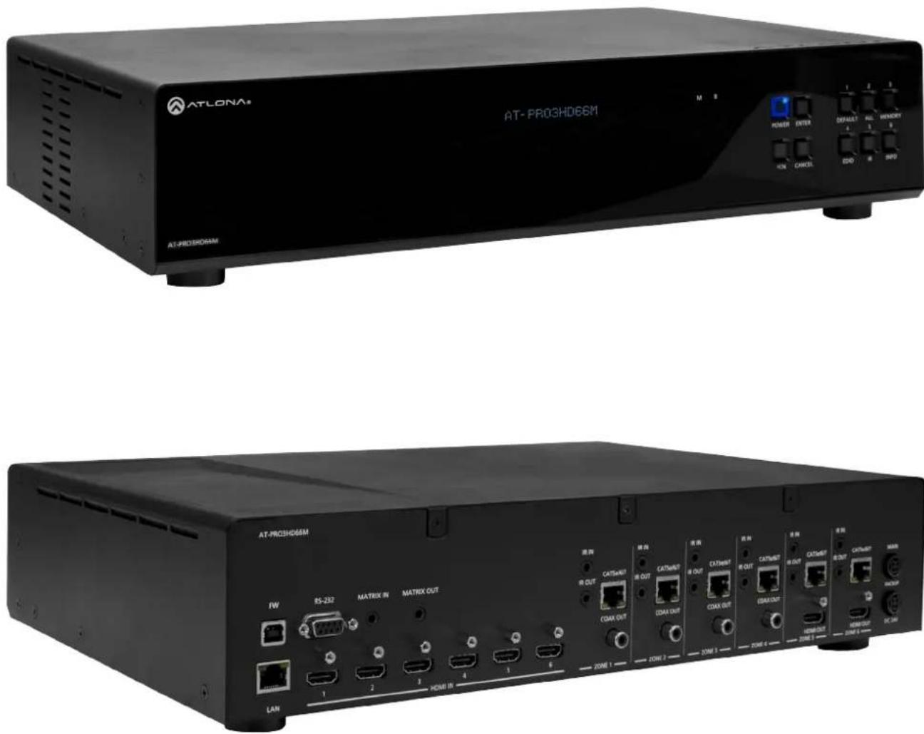
Atlona HDMI to HDBaseT 6 by 6 Matrix Switcher
AT-PRO3HD66M
User Manual
Table of Contents
-
Introduction
-
Package Contents 3
-
Features ....3
-
Before You Start 3
-
Panel Descriptions
- Front Panel
• IR 4
- Back Panel
- Connection and Installation
- 3rd Party Control 6
- IR Remote Control 7
- Matrix I/O Control 8
- I/O Route Memory 9
• EDID 9
- Matrix Status
7.RS-232
- Connection ....1
- Set Up
-
TCP/IP 14-21
-
TCP/IP and RS-232 Control
- Control Commands 22
- TCP/IP Commands
- Baud Rate
-
Remote Control 24
-
Resetting and Updating 25
-
Specifications 26
-
Safety Information 27
-
Warranty 28-29
-
Atlona Product Registration 29
Firmware 2.0.06 (8/14/13):
DHCP auto on
Page 14-21 (TCP/IP instruction has changed)
Introduction
With the latest and more affordable HDBaseT® technology extend HDMI® sources up to 230ft over category cable. The Atlona HDMI 6 by 6 Matrix Switcher allows for effortless control of up to 12 devices through IR, RS-232, TCP/IP and the front panel. With built in S/PDIF ports send audio to an AVR or distribution amp. To ensure all audio passes through, the 6 by 6 Matrix Switcher supports all Lossy and Lossless formats of Dolby® and DTSTM over HDMI.
Package Contents
- 1 x AT-PRO3HD66M
- 1 x 24V/6.25A DC adaptor
- 1 x Power cord
- 1 x IR Extender
- 7 x IR Emitter
- 1 x Remote control
- 1 x Pair of dual purpose wall/rack mounts
- 1 x User Manual
Features
- HDBaseT allows IR, RS-232, audio and visual signals to pass over a single category cable.
- Latest feature of Power over Category cable (PoCc™) enables the matrix to power all compatible receivers.
- IR ports for zone dedicated control through IR remote control and 3rd party control boxes.
- Programmable I/O memories, save I/O routes for faster switching to the most commonly used configurations.
- EDID™ learning function for up to 6 video display EDIDs.
- Built in internal EDID mode provides 12 individual EDIDs to ensure compatibility when using DVI projectors or trying to route digital multi-channel audio through an S/PDIF port
- Multiple control options such as RS-232, IR, TCP/IP, and the front panel.
- Dolby® TrueHD and DTS-HD Master Audio™ pass through HDMI output interface.
- Compatible with DVI/D (with DVI/D to HDMI adapter such as AT14050), allowing DVI/D to be passed to displays.
- Mirrored HDMI outputs on zones 5 and 6 for in room displays or AVRs
- Built in S/PDIF audio de-embedding for AVR or audio distribution amplifiers. Compatible with PCM 2Channel, Dolby 2.0, Dolby Digital 5.1, and DTS 5.1.
- Optional redundant power supply (AT-PW24V6.25A) in case the main power supply fails.
- HDCP compliant
Before You Start
- Make sure when connecting a category cable a 568B termination method is used.
- Make sure the matrix is connected to a component surge suppressor with line conditioning.
Note: Atlona's warranty does not cover damage due to electrical disturbances. A component surge suppressor with line conditioning is highly suggested, especially in areas with electrical storms. - Be sure you're using a mono to mono (2 conductor) 3.5mm IR cable when using IR output control from 3rd party control boxes, stereo (3 conductor) 3.5mm cables are not compatible.
Panel Description
Front Panel
flowchart
graph LR
    A["ATLONA"] --> B["POWER"]
    A --> C["ENTER"]
    A --> D["RESET"]
    A --> E["DATA"]
    B --> F["3"]
    C --> G["4"]
    C --> H["5"]
    D --> I["d"]
    D --> J["e"]
    D --> K["f"]
    E --> L["6"]
    style A fill:#f9f,stroke:#333
    style B fill:#ccf,stroke:#333
    style C fill:#ccf,stroke:#333
    style D fill:#ccf,stroke:#333
    style E fill:#ccf,stroke:#333
    style F fill:#cfc,stroke:#333
    style G fill:#cfc,stroke:#333
    style H fill:#cfc,stroke:#333
    style I fill:#cfc,stroke:#333
    style J fill:#cfc,stroke:#333
    style K fill:#cfc,stroke:#333
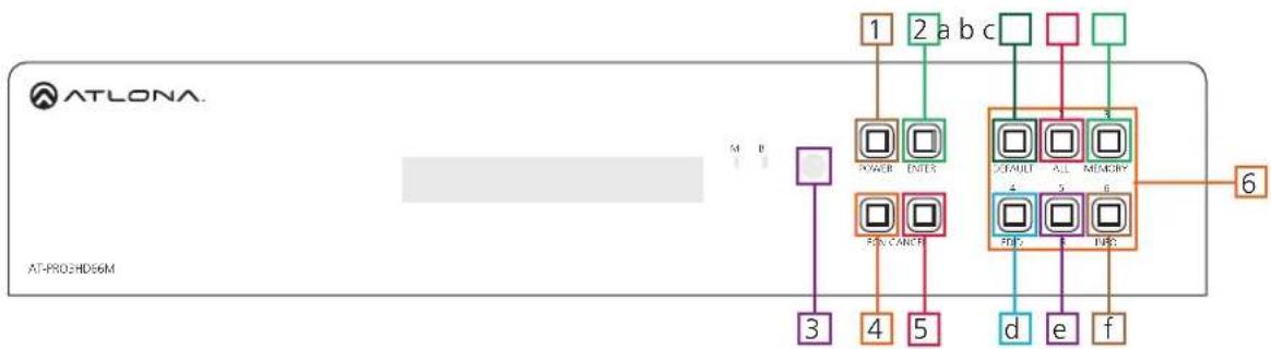
- Power Button - Cycles the power between On (blue backlight) or Standby (red backlight) mode.
- Enter Button - Use to view current status for inputs and outputs or to confirm a command.
- IR Receiver Window - Receives the signal from the included IR Remote Control or a 3rd party control box.
- Function Button - Select for command options. (blue backlight when selected)
a. Default: Mirrors all inputs to corresponding outputs. (i.e. 1 to 1, 2 to 2, 3 to 3, etc.)
b. ____ All: Save a single input to all the outputs with this function
c. Memory: Save/load the current input and output route to memory
d. EDID: Save/Load EDIDs to individual inputs
e. IR: Turn IR receiving on/off (see below)
f. INFO: Displays the firmware version on the front display
- Cancel Button - Within the functions menu use to go back one screen or to the home screen.
Note: You cannot power off or change functions unless you return to the home screen.
- Number buttons - Use these buttons to select input and output paths or use with the function button to change matrix settings.
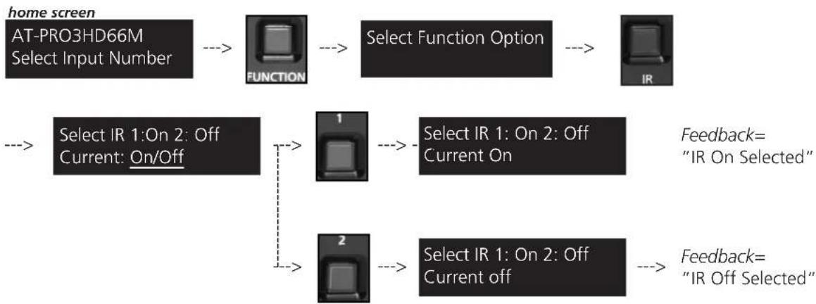
IR
The IR receiver window can sometimes pick up stray reflected IR commands causing loss of functionality. To disable the front panel, see directions below:
flowchart
graph TD
    A["home screen AT-PRO3HD66M Select Input Number"] --> B["FUNCTION"]
    B --> C["Select Function Option"]
    C --> D["IR"]
    E["Select IR 1:On 2: Off Current: On/Off"] --> F["1"]
    E --> G["2"]
    F --> H["Select IR 1: On 2: Off Current On"]
    G --> I["Select IR 1: On 2: Off Current off"]
    H --> J["Feedback="IR On Selected""]
    I --> K["Feedback="IR Off Selected""]
Back Panel
-
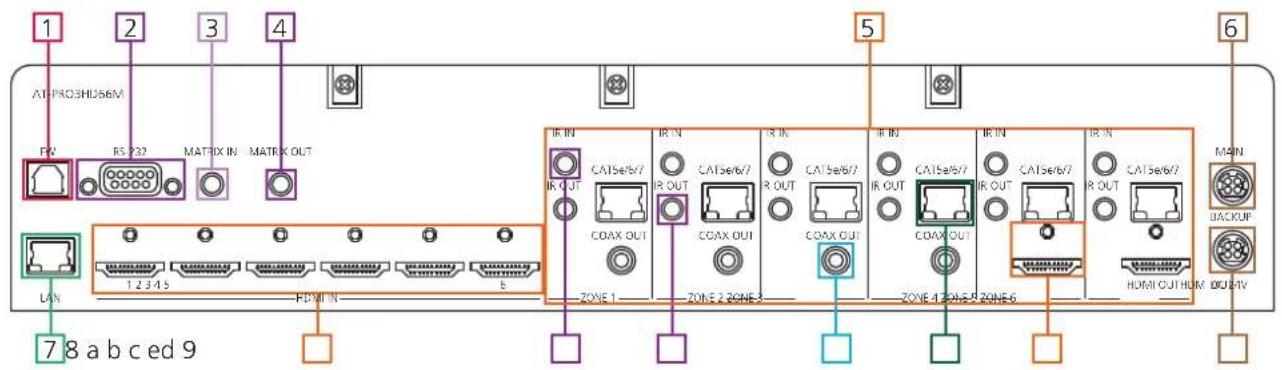
Firmware Update - Type B USB Port used for updating matrix firmware
-
RS-232 - Connect to this port for control from a computer or 3rd party control box.
-
Matrix IR In - Used to control matrix I/O switching from a 3rd party IR control box.
-
Matrix IR Out - Global output, combines IR for all incoming zones.
-
Zone dedicated ports
a. IR 3.5mm mono In ports: Used in conjunction with 3rd party IR control box to extend IR control commands to video displays over category cable.
Note: Be sure you're using a mono to mono 3.5mm IR cable for 3rd party control boxes,
3.5mm stereo cables are not compatible.
b. IR Out ports: Sends IR signal to sources through a 3.5mm IR emitter
c. Coax Out (S/PDIF): Audio de-embedding for distribution amplifiers and AVRs. Compatible with PCM 2Channel, Dolby 2.0, Dolby Digital 5.1, and DTS 5.1.
d. CAT5e/6/7 Out (RJ45): Extends video and bidirectional RS-232, IR, and audio signals through a single category cable.
e. HDMI Out: Mirrored HDMI output
-
Main Power Port - Use included locking DC adaptor to power the matrix switcher
-
LAN Port - For TCP/IP matrix control
-
HDMI Input Ports - Connect HDMI sources into these ports, such as DVD players, Blu-ray players, computers, etc.
-
Back Up Power Port - Redundant power supply (AT-PW24V6.25A available at atlona.com)
Connection and Installation
3rd Party Control box Set Up
With the feature of the IR input zone ports the AT-PRO3HD66M has the ability to receive IR commands from a 3rd party controller and send it out through the CAT5e/6/7 port to control the displays in any zone.
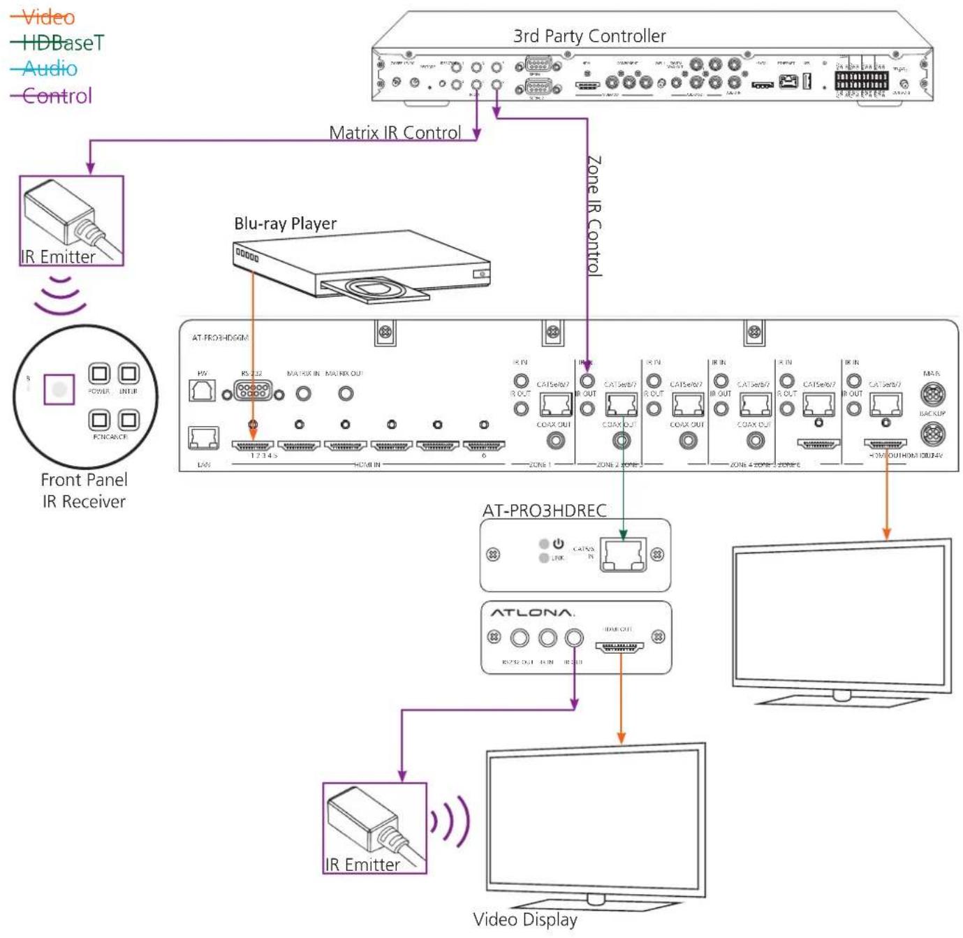
flowchart
graph TD
    A["3rd Party Controller"] -->|Matrix IR Control| B["Blu-ray Player"]
    B -->|Matrix IR Control| C["AT-PRO3HDREC"]
    C --> D["ATLONA"]
    D --> E["Video Display"]
    F["Front Panel IR Receiver"] --> G["IR Emitter"]
    G --> H["Matrix IR Control"]
    I["Video"] --> G
    J["HDBaseT"] --> G
    K["Audio"] --> G
    L["Control"] --> G
    M["Power"] --> G
    N["INTIR"] --> G
    O["FINANCE"] --> G
    P["1.2.14 S"] --> B
    Q["HDMI IN"] --> B
    R["6"] --> B
    S["Zone 1"] --> C
    T["Zone 2"] --> C
    U["Zone 4"] --> C
    V["Zone 5"] --> C
    W["Zone 6"] --> C
    X["Zone 7"] --> C
    Y["Zone 8"] --> C
    Z["Zone 9"] --> C
    AA["Zone 10"] --> C
    AB["AT PRO3HDREC"] --> AC["IR Emitter"]
    AC --> AD["Video Display"]
IR Remote Control Set Up
Note: IR signal is routed through the HDBaseT zone. Only the IR out of the corresponding zone will pass control signal when using a 3rd party IR controller
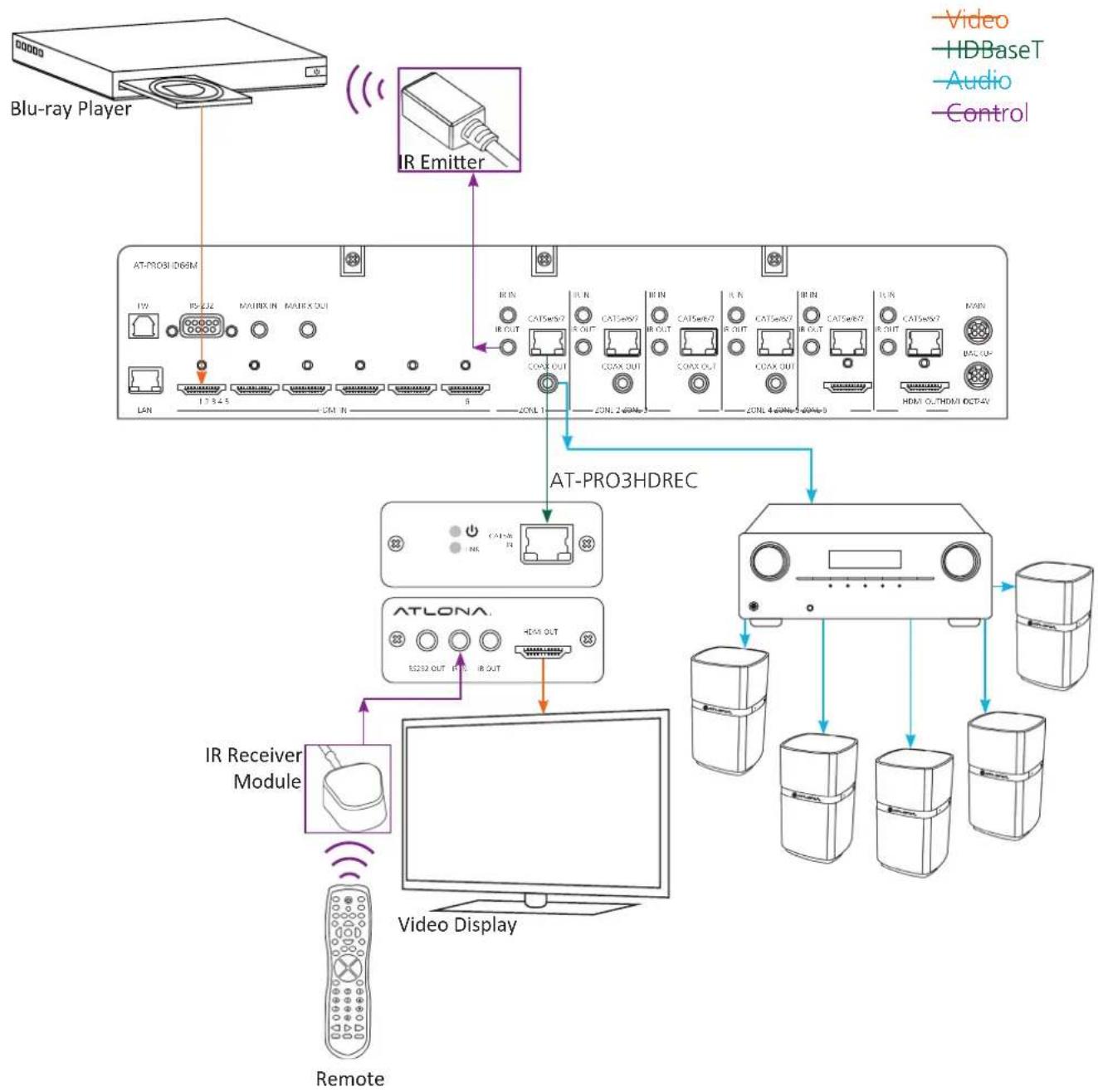
flowchart
graph TD
    A["Blu-ray Player"] --> B["AT-PRO3 HD6M"]
    B --> C["ATLONA Module"]
    C --> D["Video Display"]
    D --> E["Remote"]
    F["IR Emitter"] --> G["AT-PRO3HDREC"]
    G --> H["Video"]
    style A fill:#f9f,stroke:#333
    style B fill:#ccf,stroke:#333
    style C fill:#cfc,stroke:#333
    style D fill:#fcc,stroke:#333
    style E fill:#ffc,stroke:#333
    style F fill:#fcc,stroke:#333
    style G fill:#cff,stroke:#333
    style H fill:#ffc,stroke:#333
Matrix Front Panel Functions
The AT-PRO3HD66M's front panel has 3 functions: I/O control, EDID, and matrix settings. The following sections go over step by step setup & control.
I/O Control
To set an input to an output
(I.E. Input 1 to output 2)
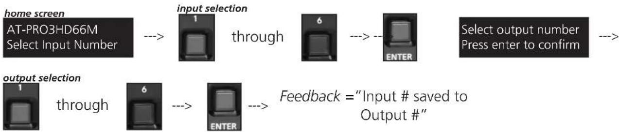
flowchart
graph LR
    A["home screen AT-PRO3HD66M Select Input Number"] --> B["input selection"]
    B --> C["through"]
    C --> D["6"]
    D --> E["--"]
    E --> F["ENTER"]
    F --> G["Select output number Press enter to confirm"]
    H["output selection"] --> I["through"]
    I --> J["6"]
    J --> K["--"]
    K --> L["ENTER"]
    L --> M["Feedback = "Input # saved to Output #""]
To mirror all inputs and outputs
(I.E. Input 1 to output 1, input 2 to output 2, etc.)

flowchart
graph LR
    A["home screen"] --> B["AT-PRO3HD66M Select Input Number"]
    B --> C["FUNCTION"]
    C --> D["Select Function Option"]
    D --> E["DEFAULT"]
    E --> F["Mirror In to Out Press enter to confirm"]
    G["ENTER"] --> H["Feedback = "Mirroring In and Out""]
To route one input to all outputs
(I.E. Input 1 to output 1, 2, 3, 4, 5 and 6)
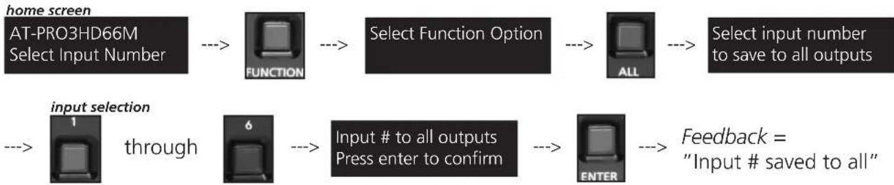
flowchart
graph LR
    A["home screen"] --> B["AT-PRO3HD66M Select Input Number"]
    B --> C["FUNCTION"]
    C --> D["Select Function Option"]
    D --> E["ALL"]
    E --> F["Select input number to save to all outputs"]
    G["input selection"] --> H["through"]
    H --> I["6"]
    I --> J["Input # to all outputs Press enter to confirm"]
    J --> K["ENTER"]
    K --> L["Feedback = "Input # saved to all""]
I/O Route Memory
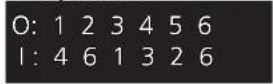
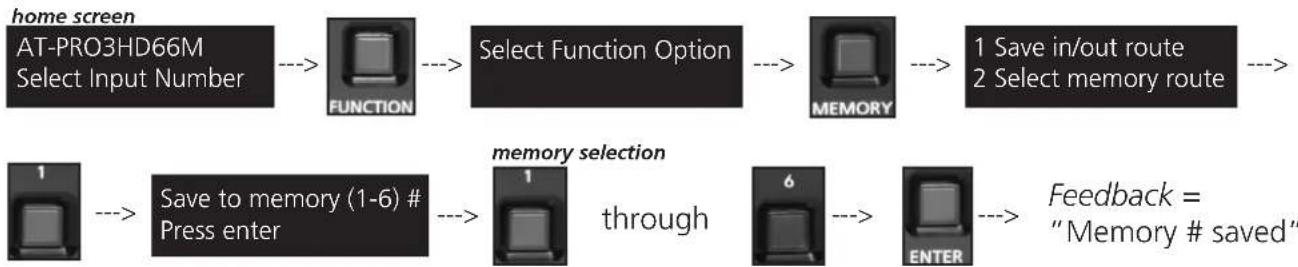
Once inputs and outputs have been set they can be saved to memory and recalled later. Up to 6 individual input/output routes can be saved. The route will remain in memory until a new route has been saved to that memory number or the matrix has been factory reset. example route
To save an I/O route to memory
example route
flowchart
graph LR
    A["home screen"] --> B["FUNCTION"]
    B --> C["Select Function Option"]
    C --> D["MEMORY"]
    D --> E["1 Save in/out route\n2 Select memory route"]
    F["1"] --> G["Save to memory (1-6) # Press enter"]
    G --> H["1 through"]
    H --> I["6 -->"]
    I --> J["ENTER"]
    J --> K["Feedback = "Memory # saved""]
To load a saved I/O route
Once an input/output route has been saved, it can be loaded at any time.

flowchart
graph LR
    A["home screen AT-PRO3HD66M Select Input Number"] --> B["FUNCTION"] --> C["Select Function Option"] --> D["MEMORY"] --> E["1 Save in/out route\n2 Select memory route"]
    F["2"] --> G["Select Memory route 1-6 Press enter to load"] --> H["memory selection through"]
    H --> I["6"] --> J["ENTER"] --> K["Feedback = "Memory # loaded""]
EDID Set Up
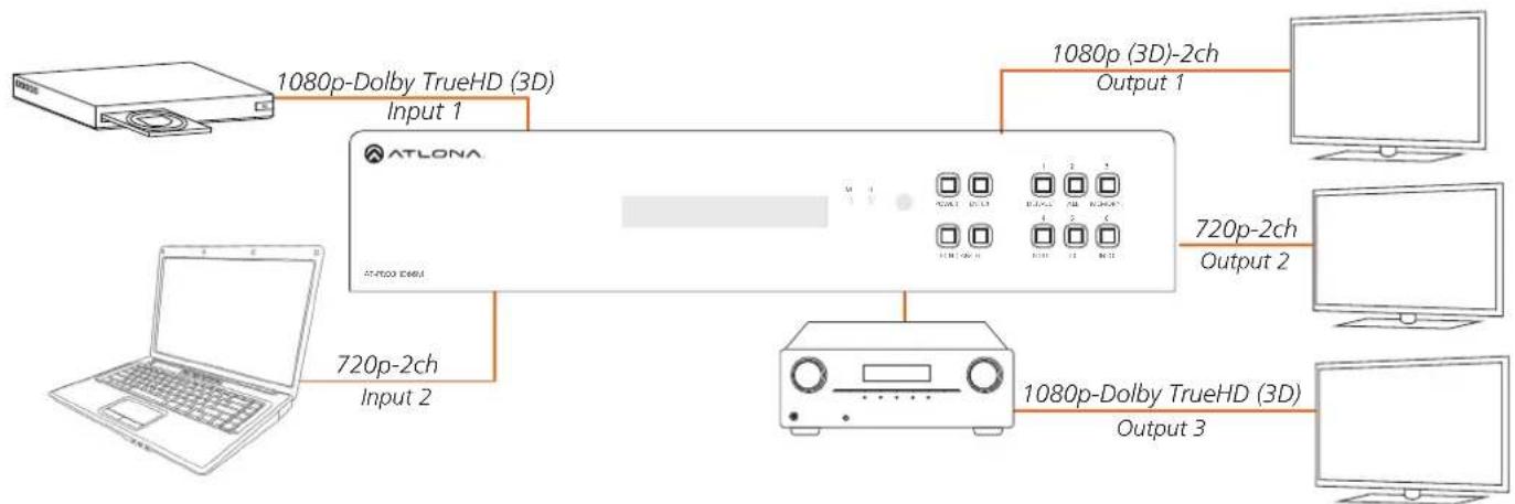
When the matrix is completely connected and turned on it will load the default EDID, which is the highest common native resolution of the devices. (i.e. In the diagram below the default would be 720p with 2ch audio. Multi-channel audio and 3D are not enabled on internal mode, unless all devices have these features.)
flowchart
graph LR
    A["ATLON"] -->|1080p-Dolby TrueHD (3D) Input 1| B["Computer"]
    A -->|720p-2ch Input 2| C["Laptop"]
    A -->|1080p (3D)-2ch Output 1| D["Computer"]
    A -->|1080p-Dolby TrueHD (3D) Output 2| E["Computer"]
    A -->|1080p-Dolby TrueHD (3D) Output 3| F["Computer"]
On default, all devices in the diagram will work at 720p. If a device is not syncing or a different resolution is required, internal EDID or EDID copy and load should resolve these issues. The PRO3HD66M can copy up to 6 EDIDs to memory.
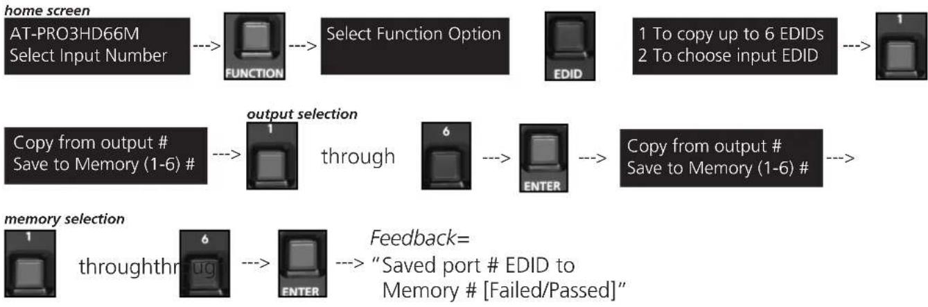
Step 1: copy an EDID
Before an EDID can be loaded to an input, it must first be copied to the matrix's memory. Each display's EDID can be saved individually to one of the matrix's six preset EDID memories.
flowchart
graph TD
    A["home screen"] --> B["AT-PRO3HD66M Select Input Number"]
    B --> C["FUNCTION"]
    C --> D["Select Function Option"]
    D --> E["EDID"]
    E --> F["1 To copy up to 6 EDIDs\n2 To choose input EDID"]
    F --> G["1"]
    H["Copy from output # Save to Memory (1-6) #"] --> I["1"]
    I --> J["output selection"]
    J --> K["through"]
    K --> L["6"]
    L --> M["ENTER"]
    M --> N["---"]
    N --> O["Copy from output # Save to Memory (1-6) #"]
    O --> P["---"]
    P --> Q["memory selection"]
    Q --> R["throughthr"]
    R --> S["6"]
    S --> T["ENTER"]
    T --> U["Feedback= "Saved port # EDID to Memory # [Failed/Passed"]"]
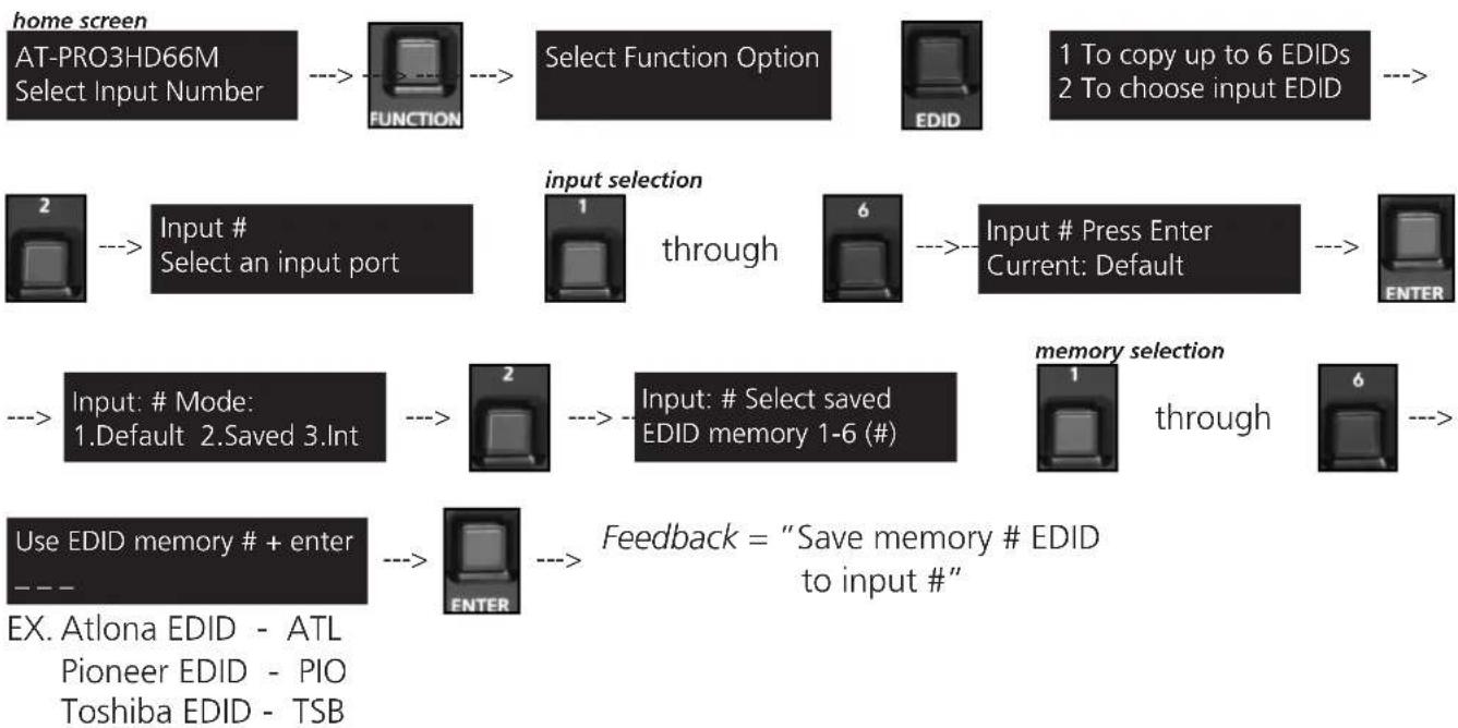
Step 2: load a copied EDID onto an input
Once EDIDs have been copied to memory they can be loaded to a specific input.
Note: (refer to the diagram on page 9) Using the EDID of output 3 with input 1 will enable 1080p, 3D, and Dolby TrueHD to pass. Output 2 will receive no audio or video and output 1 will receive no audio with these settings.
flowchart
graph TD
    A["home screen"] --> B["AT-PRO3HD66M Select Input Number"]
    B --> C["FUNCTION"]
    C --> D["Select Function Option"]
    D --> E["EDID"]
    E --> F["1 To copy up to 6 EDIDs\n2 To choose input EDID"]
    F --> G["2"]
    G --> H["Input # Select an input port"]
    H --> I["1"]
    I --> J["through"]
    J --> K["6"]
    K --> L["Input # Press Enter\nCurrent: Default"]
    L --> M["ENTER"]
    N["Input: # Mode:\n1.Default 2.Saved 3.Int"] --> O["2"]
    O --> P["Input: # Select saved\nEDID memory 1-6 (#)"]
    P --> Q["1"]
    Q --> R["through"]
    R --> S["6"]
    S --> T["END"]
    U["Use EDID memory # + enter"] --> V["--"]
    V --> W["ENTER"]
    W --> X["Feedback = "Save memory # EDID\nto input #""]
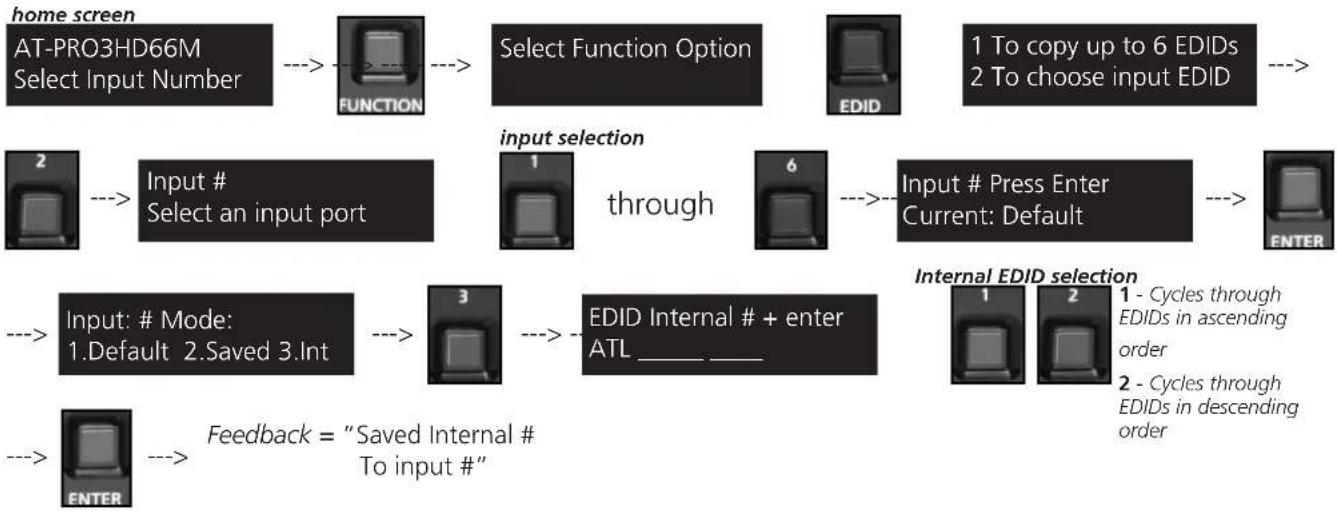
Step 3: Load an internal EDID on an input
If the first two steps don't produce the correct resolution or audio configuration, the twelve internal EDIDs should resolve the issue.
Internal EDID options
Front panel display readout
EDID 1: 1080P 2CH audio ATL 1080P 2CH
EDID 2: 1080P HD multi-channel audio 7.1* ATL 1080P Multi CH
EDID 3: 1080P Dolby Digital/DTS 5.1** ATL 1080P DD
EDID 4: 1080P 3D 2CH audio ATL 1080P 3D 2CH
EDID 5: 1080P 3D HD multi-channel audio 7.1* ATL 1080P 3D Multi CH
EDID 6: 1080P 3D Dolby Digital/DTS 5.1** ATL 1080P 3D DD
EDID 7: 720P 2CH audio ATL 720P 2CH
EDID 8: 720P Dolby Digital/DTS 5.1** ATL 720P DD
EDID 9: 1280x800 RGB 2CH audio ATL 1280x800 RGB 2CH
EDID 10: 1366x768 RGB 2CH audio ATL 1366x768 RGB 2CH
EDID 11: 1080P DVI*** ATL 1080P DVI
EDID 12: 1280x800 DVI*** ATL 1280x800 RGB DVI
* Recommended EDID for use of an AVR
** Recommended EDID for use of the S/PDIF audio de-embedding
*** Recommended EDID for use of DVI projectors
flowchart
graph TD
    A["home screen"] --> B["AT-PRO3HD66M Select Input Number"]
    B --> C["FUNCTION"]
    C --> D["Select Function Option"]
    D --> E["EDID"]
    E --> F["1 To copy up to 6 EDIDs\n2 To choose input EDID"]
    F --> G["2"]
    G --> H["Input # Select an input port"]
    H --> I["1"]
    I --> J["through"]
    J --> K["6"]
    K --> L["Input # Press Enter\nCurrent: Default"]
    L --> M["ENTER"]
    N["Input: # Mode:\n1.Default 2.Saved 3.Int"] --> O["3"]
    O --> P["EDID Internal # + enter\nATL______"]
    Q["Feedback = "Saved Internal #\nTo input #""] --> R["ENTER"]
    S["Internal EDID selection"] --> T["1 - Cycles through EDIDs in ascending order\n2 - Cycles through EDIDs in descending order"]
RS-232 commands:
To access the different EDIDs through RS-232 the following commands must be used.
| Command | Feedback | Description |
| EDIDMSetX default | EDIDMSetX default | Sets the EDID of an input to the default EDIDEx. EDIDMset2 default - sets input 2 to default |
| EDIDMSetX saveY | EDIDMSetX saveY | Sets the EDID of an input to the previously saved EDID memoryEx. EDIDMset1 save3 - sets input 1 to the EDID memory 3 |
| EDIDMSetX intZ | EDIDMSetX intZ | Sets the EDID of an input to one of the internal EDIDsEx. EDIDMset3 int6 - sets input 3 to the internal EDID - 1080p 3D Dolby Digital 5.1 |
Matrix Status
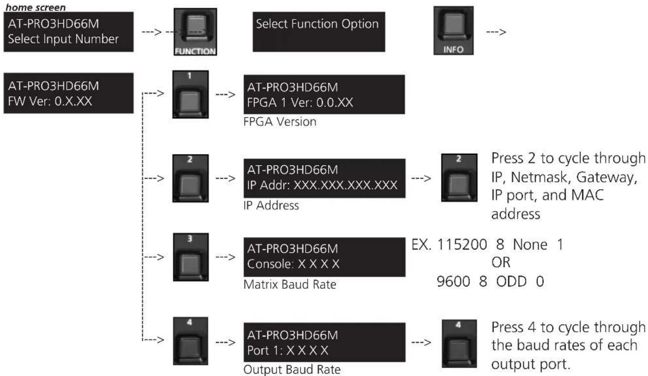
When installing or troubleshooting it's important to verify settings, or be able to come back to a project and see how it was set up. The AT-PRO3HD66M matrix settings are viewable through the front panel display. View current I/O settings, firmware version, FPGA version, IP, and the baud rates of not just the matrix but extenders as well.
View current I/O settings

View Firmware/Baud Rate/FPGA settings
flowchart
graph TD
    A["home screen"] --> B["FUNCTION"]
    B --> C["Select Function Option"]
    C --> D["INFO"]
    E["AT-PRO3HD66M FW Ver: 0.X.XX"] --> F["1"]
    F --> G["AT-PRO3HD66M FPGA Version"]
    G --> H["2"]
    H --> I["AT-PRO3HD66M IP Address: XXX.XXX.XXX.XXX"]
    I --> J["3"]
    J --> K["AT-PRO3HD66M Console: X X X X Matrix Baud Rate"]
    K --> L["4"]
    L --> M["AT-PRO3HD66M Port 1: X X X X Output Baud Rate"]
    M --> N["4"]
    style A fill:#f9f,stroke:#333
    style E fill:#f9f,stroke:#333
    style K fill:#f9f,stroke:#333
RS-232
Connection
RS-232 is connected through a 9-pin female DB connector. Only pins 2, 3, and 5 are terminated.
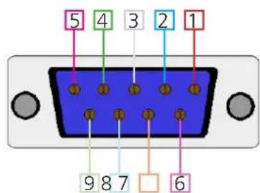
| No. Pin Function | ||
| 1 ---- | Not used | |
| 2 Tx | Transmit | |
| 3 Rx | Receive | |
| 4 ---- | Not used | |
| 5 Grid | Ground | |
| 6 ---- | Not used | |
| 7 ---- | Not used | |
| 8 ---- | Not used | |
| 9 ---- | Not used | |
Set Up
To set up the RS-232 hyperterminal (if not using 3rd party software) use the following steps:
- Connect the matrix to a PC using a 9pin to 9pin cable
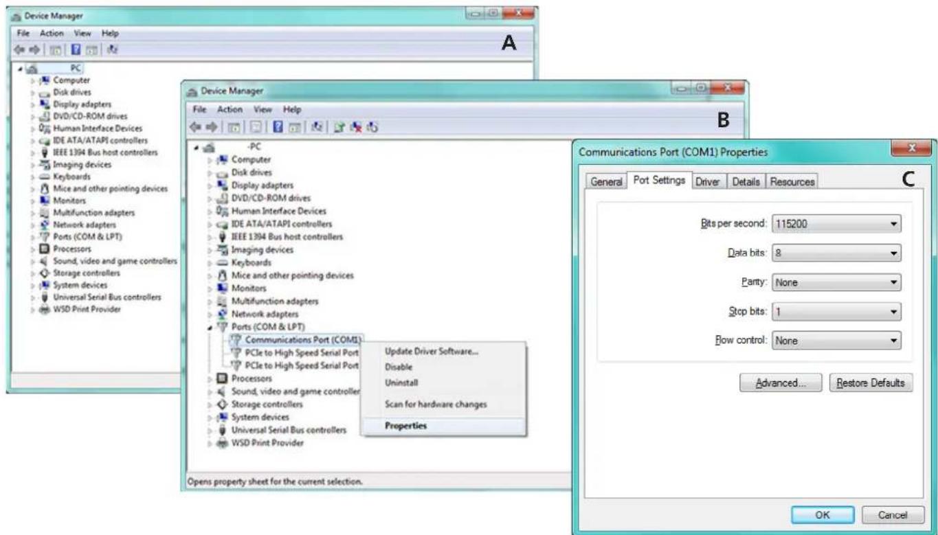
- Go to the Device manager folder (see picture A)
-
Find the Matrix COM port and right click with a mouse and select properties (see picture B). NOTE: If unsure which COM port is the matrix, unplug the 9pin cable and plug it back in. It will disappear and reappear on the COM port list.
-
Under the properties menu select the port settings tab and update the menu to the matrix default settings of: Bits Per Second: 115200, Data Bits: 8, Parity: None, Stop Bits: 1 and Flow Control: None. (see picture C)
Set up is done and any hyperterminal program may be used to control the matrix now.
TCP/IP
For convenience, the matrix comes with DHCP default on. This enables the matrix to be connected to a network or network device with no worries of the matrix IP overriding another device.
TCP/IP WebGUI
Atlona has created an easy to use WebGUI for changing settings and controlling the matrix.
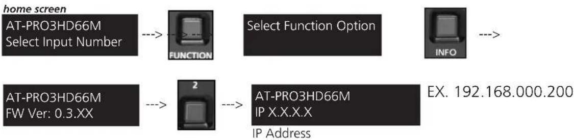
To begin, plug a LAN cable into the matrix and your network, then type the IP address of the matrix into a web browser (as seen below).

To find the matrix IP:
flowchart
graph LR
    A["home screen"] --> B["AT-PRO3HD66M Select Input Number"]
    B --> C["FUNCTION"]
    C --> D["Select Function Option"]
    D --> E["INFO"]
    F["AT-PRO3HD66M FW Ver: 0.3.XX"] --> G["2"]
    G --> H["AT-PRO3HD66M IP X.X.X.X"]
    H --> I["EX. 192.168.000.200"]
    I --> J["IP Address"]
Important: If any stability issues are experienced, disable any anti-virus or firewall that may be interfering with network communication to the Matrix. Once set up is done and the matrix GUI is no longer being used, the firewall and anti-virus can be re-enabled.
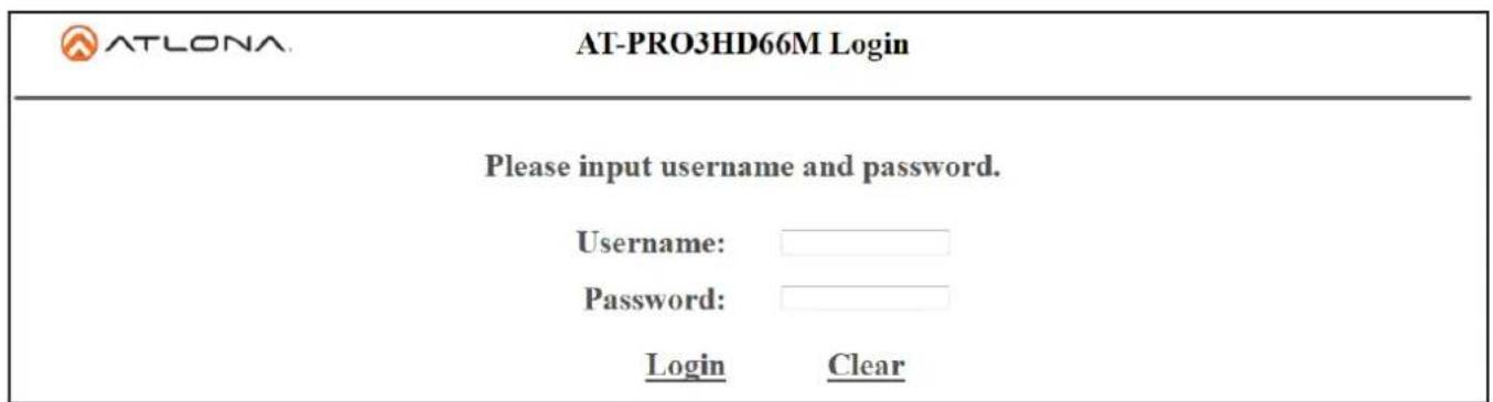
A login screen will appear (this is the same log in for admin and general users). For the first log in (and future admin changes) the username is "root" and password is "Atlona".
Note: Only the admin password can be changed (see page 18). The username will always remain "root".
The home screen tab will display the general system information. If the matrix is powered off the FPGA will not display (see first image). Once the power is on it will display (see second image).
Note: When the matrix is turned off many fields within the WebGUI will not display information. Be sure the matrix is powered on for complete access.
| AT-LONA. | AT-PRO3HD66M | |
| Home | Network Setup | Status/Setting |
| Model: | AT-PRO3HD66M | |
| Firmware Version: | 0.3.17 | |
| FPGA Version: | Please turn on the power | |
| Hardware Version: | A | |
| MAC Address: | B8-98-B0-00-00-00 | |
| ATLONA. AT-PRO3HD66M | ||
| Home | Network Setup | Status/Setting |
| Model: | AT-PRO3HD66M | |
| Firmware Version: | 0.3.17 | |
| FPGA Version: | 0.5.00 | |
| Hardware Version: | A | |
| MAC Address: | B8-98-B0-00-00-00 | |
| ATLONA AT-PRO3HD66M Setup | ||
| Home | Network Setup | Status/Setting |
| DHCP | ON OFF | |
| IP Address | 192.168.000.200 | |
| Subnet | 255.255.255.000 | |
| Gateway | 192.168.000.001 | |
| Telnet Port | 23 | |
| Login Mode | ON OFF | |
The network set up page will allow the IP information to be changed. When a change is made the screen will grey and the ability to save or cancel will display at the bottom (see below).
Note: When DHCP is on, the IP cannot be configured. Turn DHCP off to enable IP configuration.
Note: For a stable connection, when using a control system it is best to set up a static IP.
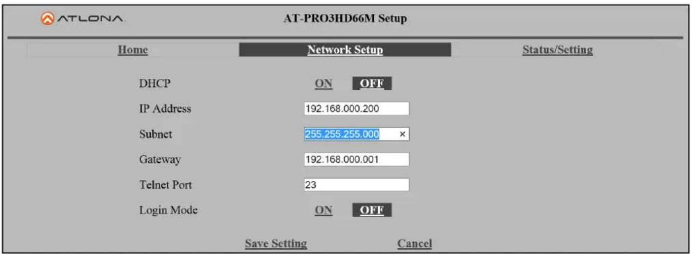
Note: Be sure to save all changes before moving to the next page
Login Mode has been added to provide a secure telnet login. Once Login Mode has been turned on a username and password will be required on all IP connections to the matrix.
Note: Login Mode should not be used when using a control system.
Note: The username and password used in IP Login Mode will be the same login information as the WebGUI
The config page under status/setting will allow power to be turned off/on, the front IR window to be turn off/on (see page 4), and the matrix and zone baud rates to be changed (see page 23-24).
| AT-LONA AT-PRO3HD66M Config | |||||
| Home | Network Setup | Status/Setting | |||
| CONFIG | I/O | EDID | HDCP | ||
| Power | ON | OFF | |||
| IR | ON | OFF | |||
| Factory Default Reset All Parameters | |||||
| No. | Baudrate | Databit | Parity | Stopbit | |
| Matrix | 115200 | 8 Bits | None | 1 Bit | |
| Port 1 | 9600 | 8 Bits | None | 1 Bit | |
| Port 2 | 9600 | 8 Bits | None | 1 Bit | |
| Port 3 | 9600 | 8 Bits | None | 1 Bit | |
| Port 4 | 9600 | 8 Bits | None | 1 Bit | |
| Port 5 | 9600 | 8 Bits | None | 1 Bit | |
| Port 6 | 9600 | 8 Bits | None | 1 Bit | |
| No. | Username | Password | Delete | ||
| User 1 | Delete | ||||
| User 2 | Delete | ||||
| User 3 | Delete | ||||
A grey screen will display the save and cancel options when making changes. Remember to save all settings before moving on to the next page.
Note: All like fields can be changed during one edit.
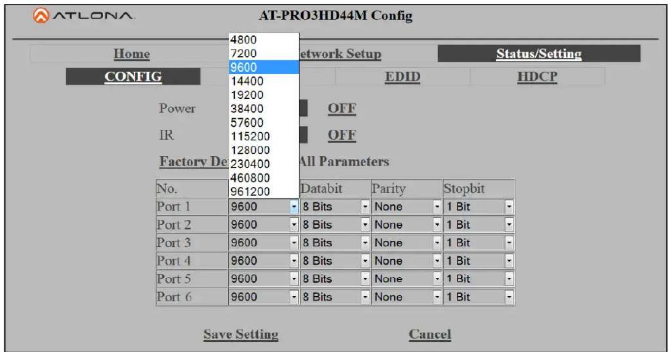
Note: This part of the config page will display for the admin only.
Adding, deleting, and updating users can also be done from the config page. User changes can only be done by the admin. Admin user name is always "root" and default password is "Atlona".
Note: Only the admin password can be changed. The username will always remain "root"
| No. | Username | Password | Delete | ||
| User 1 | Delete | ||||
| User 2 | Delete | ||||
| User 3 | Delete | ||||
Note: Always remember to save settings before moving to the next page
| No. | Username | Password | Delete | ||
| User 1 | Atlona | Matrix | Delete | ||
| User 2 | Pro3 | RS-232 | Delete | ||
| User 3 | Delete | ||||
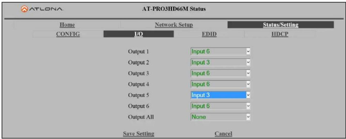
The I/O page allows input and output routes to be changed easily by drop down menu. Output All will route one selected input to all the outputs.
| AT-LONA AT-PRO3HD66M Status | |||
| Home | Network Setup | Status/Setting | |
| CONFIG | I/O | EDID | HDCP |
| Output 1 | Input 6 | ||
| Output 2 | Input 6 | ||
| Output 3 | Input 6 | ||
| Output 4 | Input 6 | ||
| Output 5 | Input 6 | ||
| Output 6 | Input 6 | ||
| Output All | None | ||
Note: All routes can be changed while in the grey edit screen. Remember to save after all changes have been made.
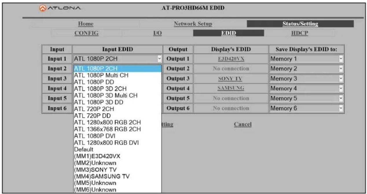
For compatibility and ease of use, EDID configuration has been added. Each input has a drop down selection for internal, default, and saved EDIDs (see pages 9-11 for EDID information).
Note: When saving an EDID to memory through the WebGUI, the output will save to the corresponding memory. Ex. Output 2 will only save to Memory 2
| ATLONA AT-PRO3HD66M EDID | ||||
| Home | Network Setup | Status/Setting | ||
| CONFIG | I/O | EDID | HDCP | |
| Input | Input EDID | Output | Display's EDID | Save Display's EDID to: |
| Input 1 | ATL 1080P 2CH | Output 1 | E3D420VX | Memory 1 |
| Input 2 | ATL 1080P 2CH | Output 2 | No connection | Memory 2 |
| Input 3 | ATL 1080P 2CH | Output 3 | SONY TV | Memory 3 |
| Input 4 | ATL 1080P 2CH | Output 4 | SAMSUNG TV | Memory 4 |
| Input 5 | ATL 1080P 2CH | Output 5 | No connection | Memory 5 |
| Input 6 | ATL 1080P 2CH | Output 6 | No connection | Memory 6 |
Internal EDIDs (see page 11) provide 12 options for video and audio to ensure compatibility and reliability.
Auto default mode will choose the highest common video resolution and audio format that is supported by all outputs.
Each EDID saved to memory will be noted as MM and the number of its output.
**Clicking on the Display's EDID link will provide a breakdown of the selected output's EDID
Note: MM#s in the picture above are examples of saved EDIDs
Note: Remember to save after all changes to ensure complete compatibility.
The HDCP page will display the output's ability to pass HDCP or not.
Several messages will appear under different circumstances:
Supported - HDCP is supported by the display
Not Supported - The display is unable to support HDCP
Non-HDCP Source - A source that does not support HDCP
No connection - If no source is selected/connected, HDCP status cannot be determined
| AT-LONA AT-PRO3HD66M HDCP | |||
| Home | Network Setup | Status/Setting | |
| CONFIG | I/O | EDID | HDCP |
| Output 1 | Supported | ||
| Output 2 | No connection | ||
| Output 3 | Non-HDCP Source | ||
| Output 4 | Supported | ||
| Output 5 | No connection | ||
| Output 6 | No connection | ||
RS-232 & TCP/IP Control Commands
The command codes are case sensitive, do not change capitalization, spacing, or lettering.
| Command Feedback Description | ||
| PWON PWON Power on | ||
| PWOFF PWOFF Power off | ||
| PWSTA PWx Will display the power status of the matrix (ex. Power is on = PWON) | ||
| Version | (Firmware #) | Brings up the current firmware version |
| Type | (Model #) Brings up the model information | |
| Lock | Lock | Locks the front panel of the matrix so no buttons are active |
| Unlock | Unlock | Unlocks the front panel of the matrix, enabling the buttons again |
| All# | x1AVx1,x2AVx2,... | Resets all inputs to corresponding outputs (in3 to out3) |
| x1 | x1 | Turns off output channel (to turn off output 3 = x3$) |
| x1All | x1All | Sets selected input to all outputs(x3All would set input 3 to all) |
| x1AVx2 | x1AVx2 | Switch input to output (input 3 to output 2 = x3AVx2) |
| x1AVx2,x3,x4 | x1AVx2,x3,x4 | Switch input to multiple outputs (input 3 = x3AVx1,x2) |
| IRON | IRON | Turns on the IR receiver |
| IROFF | IROFF | Turns off the IR receiver |
| Statusx1 | x7AVx1 | Shows what input is connected to selected output |
| Status | x1AVx1,x2AVx2,x3AVx4,.... | Displays which inputs are currently connected to which outputs |
| SaveY (ex. Save2) | SaveY (ex. Save2) | Saves settings for future use, preset options 0 to 4 |
| RecallY (ex. Recall2) | RecallY (ex. Recall2) | Recalls saved settings for the number you selected |
| ClearY (ex. Clear2) | ClearY (ex. Clear2) | Erases the save for the number you selected |
| Mreset | Mreset | Sets matrix back to the default settings |
| RS232zoneX[command]ex: RS232zone1[PWON] | RS232zoneX[command]ex: RS232zone1[PWON] | Send commands to devices connected to the receiver RS-232 ports Sierra Commands are the same as the ones stated in this table.X = zone numberexample: Turning the power on for the device connected in zone 1 |
Each command or feedback is terminated with a carriage return.
Note: If the command fails or is incorrect the feedback should be "Command FAILED"
TCP/IP Commands
| Command Feedback Description | ||
| IPCFG IP Addr : x.x.x.x | Netmask : x.x.x.xGateway : x.x.x.xIP Port: x.x.x | Displays IP address configuration |
| IPTimeout XX IPTimeout XX(Ex. IPTimout120) | Determines amount of seconds of inactivity before TCP/IP disconnects | |
| IPQuit IPQuit Logs out of TCP/IP | ||
| IPAddUser TCP/IP username & password list:- user password- user password- user password | Will display a list of users | |
| IPAddUser [X] [Y] TCP/IP user was added Add a user for TCP/IP control. X=User Y=PasswordEx. IPAddUser Atlona 1234 (User=Atlona 1234=Password) | ||
TCP/IP Commands Cont.
| IPDelUser [X] TCP/IP user was deleted Delete a user from TCP/IP X=User (Ex. IPDelUser Atlona) | |
| IPDHCP sta IPDHCP sta Ex. IPDHCP on | Displays the status of DHCP |
| IPDHCP on IPDHCP on Turns DHCP on | |
| IPDHCP off IPDHCP off Turns DHCP off | |
| IPStatic [X] [Y] [Z] IPS static address netmask gateway Sets a static IP address Ex. IPStatic 192.168.1.1 255.255.255.0 192.168.1.200 | |
| IPPort IIPort Y Set the TCP/IP port (ex. IIPort 230) | |
| IPLogin sta IPLogin sta Ex. IPLogin on | Displays IPLogin status |
| IPLogin on IPLogin on Enables IPLogin | |
| IPLogin off IPLogin off Disables IPLogin | |
| Broadcast sta Broadcast sta Displays broadcast mode status | |
| Broadcast on Broadcast on | Enables broadcast mode |
| Broadcast off Broadcast off Disables broadcast mode | |
Baud Rate
Default baud rates of the matrix and receivers have been set for the best compatibility with other devices (i.e. projectors). Baud rates should not be changed unless an incompatibility occurs.
To change the baud rate of the matrix or the receiver (AT-PRO3HDREC) an RS-232 hyperterminal will be needed. Once the RS-232 hyperterminal is set up changing the baud rate will be done with a command line. The baud rate for the matrix is for matrix control and the output baud rate is for control of the RS-232 device in the zone being controlled.
Note: Baud rate options 2400, 4800, 9600, 19200, 38400, 57600, or 115200
Command for Matrix baud rate
CSpara[baudrate, data-length, parity, stop-bit] (data, parity, and stop for matrix must be 8,0,1)
For example if you wish to change the baud rate to 38400 the command would look like this: CSpara[38400,8,0,1]
Note: Default for the matrix is: Baud-115200bps, Data length-8bit, Parity-None, Stop Bit-1
RS-232 Command for the Output baud rate status
RS232para
The RS-232 status command will provide feedback for the current parameters for each output.
Example: (See example of feedback below)
RS232para
Current RS232 parameter:
- Port 1 :BaudRate 2400bps, DataBits 0, Parity None, StopBits 1.
- Port 2 :BaudRate 9600bps, DataBits 0, Parity ODD, StopBits 1.
- Port 3 :BaudRate 9600bps, DataBits 0, Parity None, StopBits 1.
- Port 4 : BaudRate 9600bps, DataBits 0, Parity None, StopBits 1.
Note: Default for the outputs is: Baud-9600bps, Data length-8bit, Parity-None, Stop Bit-1
The ability to check baud rate status on the outputs will help to identify control compatibility for in zone RS-232 devices.
Command for Output (receiver) baud rate
RS232paraX[baudrate, data-length, parity, stop-bit]
X represents the zone# (output#), the data length must be 7 or 8, partity bit will be 0 for none, 1 for odd, 2 for even, and the stop-bit must be 1 or 2.
For example if you wish to change the baud rate to 19200, data length 8, ODD parity, and 1 stop-bit on the receiver in zone 3 to 19200 the command would look like this:
RS232para3[19200,8,1,1]
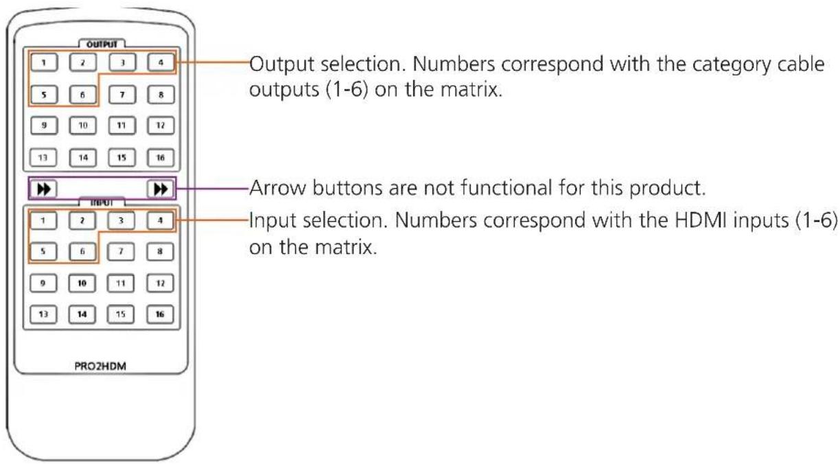
Remote Control
Updating and Resetting
Updating firmware
Atlona has made field firmware updating easy. Simply download firmware from Atlona.com and upload the file to the matrix.
NOTE: Only use a Windows computer to update the matrix. Use of an Apple computer to update will cause the matrix to be unusable until the update is redone with a Windows computer.
Needs:
- Verify the current firmware version
• RS-232 9 Pin to 9 Pin cable.
• PC (not compatible with MAC)
• OS that supports USB mass storage devices - USB A to USB B cable
To view the current firmware use RS-232 command "Version".
Preparing the Matrix:
- Unplug the power cable.
- Hold the Cancel button while plugging the power back in.
- Connect the USB B to USB A cable into the Matrix and the Computer.
Updating the Matrix:
The computer should auto detect the connection, if it does not, open the USB device from "my computer".
- Click open in a new folder. (if auto run detects connection)
- Delete the file in the folder. (there should be only one file, if more, delete all files)
- Copy and Paste the new firmware file into the USB folder.
- Unhook the Matrix from the computer.
- Unplug the power cable from the AT-PRO3HD66M
- Plug the power back in and start the matrix normally. Your update should be complete
If you wish to verify the new firmware, use the RS-232 command "Version".
Resetting to factory settings
Atlona understands that settings can be troublesome and at times its just easier to set things back to factory settings. To make things easier a simple one step reset was created.
To reset the matrix, hold down the buttons 1 and 4 while powering on. If successful the matrix will be back to factory settings when it turns on.
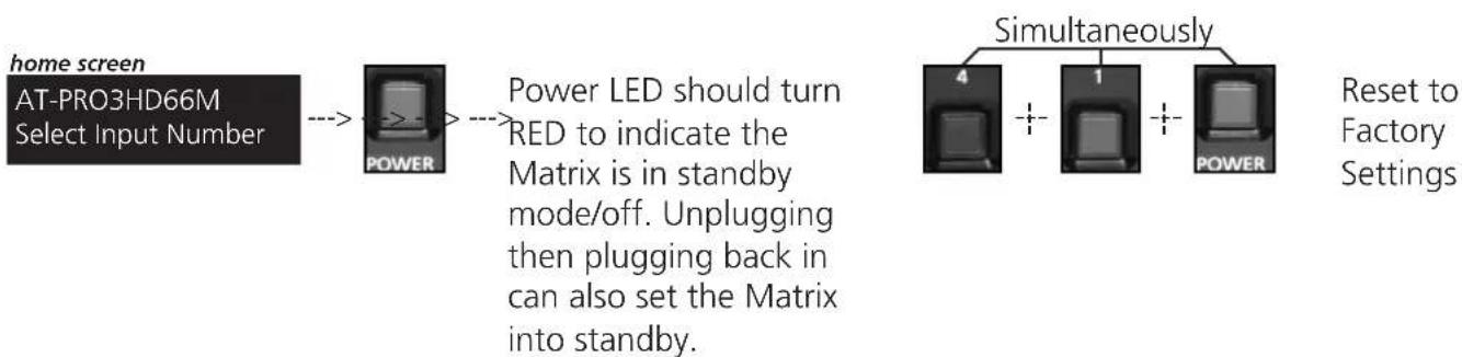
flowchart
graph LR
    A["home screen<br>AT-PRO3HD66M<br>Select Input Number"] --> B["POWER"]
    B --> C["Power LED should turn RED to indicate the Matrix is in standby mode/off. Unplugging then plugging back in can also set the Matrix into standby."]
    D["Simultaneously"] --> E["4"]
    D --> F["1"]
    D --> G["POWER"]
    G --> H["Reset to Factory Settings"]
Specifications
| Bandwidth 6.75Gbps | ||
| PortsVideo inputVideo outputAudio outputIR inputIR outputControl: RS-232Control: TCP/IPFirmware update | 6 x HDMI6 x RJ45, 2 x HDMI4 x S/PDIF7 x 3.5mm7 x 3.5 mm1 x 9pin (RS-232)1 x RJ451 x USB B | |
| Power Consumption 90W | ||
| Audio Passes up to Dolby | TrueHD or DTS-HD Master Audio | |
| Distance 230ft (70m) @ 1 | 080p over CAT6a/7197ft (60m) @ 1080p over CAT5e/6 | |
| Resolution Video: up to 1 | 080p@60HzVESA: up to 1920x1200 | |
| Dimensions | 3.45 x 17.24 x 10.98 (inch)87.5 x 438 x 279 (mm) | |
| Weight | 9.55 lbs4.32 kg | |
| Rack Size 2 U, 19 in. standard electronics rack | ||
| Temperature Operating | 32°F to 104°F0°C to 40°C | Storage-4°F to 140°F-20°C to 60°C |
| Certifications CE, FCC, RoHS, cULus for power supplies | ||
Safety Information
Safeguards

To reduce the risk of electric shock, do not expose this product to rain or moisture

If the wall plug does not fit into your local power socket, hire an electrician to replace your obsolete socket.

Do not modify the wall plug. Doing so will void the warranty and safety features.
This equipment should be installed near the socket outlet and the device should be easily accessible in the case it requires disconnection.
Precautions
FCC regulations state that any unauthorized changes or modifications to this equipment, not expressly approved by the manufacturer, could void the user's authority to operate this equipment.
Operate this product using only the included external power supply. Use of other power supplies could impair performance, damage the product, or cause fires.
In the event of an electrostatic discharge this device may automatically turn off. If this occurs, unplug the device and plug it back in.
Protect and route power cords so they will not be stepped on or pinched by anything placed on or against them. Be especially careful of plug-ins or cord exit points from this product.
Avoid excessive humidity, sudden temperature changes or temperature extremes.
Keep this product away from wet locations such as bathtubs, sinks, laundries, wet basements, fish tanks, and swimming pools.
Use only accessories recommended by Atlona to avoid fire, shock, or other hazards.
Unplug the product before cleaning. Use a damp cloth for cleaning and not cleaning fluid or aerosols. Such products could enter the unit and cause damage, fire, or electric shock. Some substances may also mar the finish of the product.
Never open, remove unit panels, or make any adjustments not described in this manual. Attempting to do so could expose you to dangerous electrical shock or other hazards. It may also cause damage to your product. Opening the product will void the warranty.
Do not attempt to service the unit. Disconnect the product and contact your authorized Atlona reseller or contact Atlona directly.
Atlona, Inc. ("Atlona") Limited Product Warranty Policy
Coverage
Atlona warrants its products will substantially perform to their published specifications and will be free from defects in materials and workmanship under normal use, conditions and service.
Under its Limited Product Warranty, Atlona, at its sole discretion, will either:
A) repair or facilitate the repair of defective products within a reasonable period of time, restore products to their proper operating condition and return defective products free of any charge for necessary parts, labor and shipping OR
B) replace and return, free of charge, any defective products with direct replacement or with similar products deemed by Atlona to perform substantially the same function as the original products
OR
C) refund the pro-rated value based on the remaining term of the warranty period, not to exceed MSRP, in cases where products are beyond repair and/or no direct or substantially similar replacement products exist.
Repair, replacement or refund of Atlona's products is the purchaser's exclusive remedy and Atlona's liability does not extend to any other damages, incidental, consequential or otherwise.
This Limited Product Warranty extends to the original end-user purchaser of Atlona's products and is non-transferrable to any subsequent purchaser(s) or owner(s) of these products.
Coverage Periods
Atlona's Limited Product Warranty Period begins on the date of purchase by the end-purchaser. The date contained on the end-purchaser 's sales or delivery receipt is the proof purchase date.
Limited Product Warranty Terms – New Products
• 10 years from proof of purchase date for hardware/electronics products purchased on or after June 1, 2013
• 3 years from proof of purchase date for hardware/electronics products purchased before June 1, 2013
• Lifetime Limited Product Warranty for all cable products
Limited Product Warranty Terms – Refurbished (B-Stock) Products
- 3 years from proof of purchase date for all Refurbished (B-Stock) hardware and electronic products purchased on or after June 1, 2013
Remedy
Atlona recommends that end-purchasers contact their authorized Atlona dealer or reseller from whom they purchased their products. Atlona can also be contacted directly. Visit www.atlona.com for Atlona's contact information and hours of operation. Atlona requires that a dated sales or delivery receipt from an authorized dealer, reseller or end-purchaser is provided before Atlona extends its warranty services. Additionally, a return merchandise authorization (RMA) and/or case number, is required to be obtained from Atlona in advance of returns.
Atlona requires that products returned are properly packed, preferably in the original carton, for shipping. Cartons not bearing a return authorization or case number will be refused. Atlona, at its sole discretion, reserves the right to reject any products received without advanced authorization. Authorizations can be requested by calling 1-877-536-3976 (US toll free) or 1-408-962-0515 (US/international) or via Atlona's website at www.atlona.com.
Exclusions
This Limited Product Warranty excludes:
- Damage, deterioration or malfunction caused by any alteration, modification, improper use, neglect, improper packing or shipping (such claims must be presented to the carrier), lightning, power surges, or other acts of nature.
- Damage, deterioration or malfunction resulting from the installation or removal of this product from any installation, any unauthorized tampering with this product, any repairs attempted by anyone unauthorized by Atlona to make such repairs, or any other cause which does not relate directly to a defect in materials and/or workmanship of this product.
- Equipment enclosures, cables, power supplies, batteries, LCD displays, and any accessories used in conjunction with the product(s).
- Products purchased from unauthorized distributors, dealers, resellers, auction websites and similar unauthorized channels of distribution.
Disclaimers
This Limited Product Warranty does not imply that the electronic components contained within Atlona's products will not become obsolete nor does it imply Atlona products or their electronic components will remain compatible with any other current product, technology or any future products or technologies in which Atlona's products may be used in conjunction with. Atlona, at its sole discretion, reserves the right not to extend its warranty offering in instances arising outside its normal course of business including, but not limited to, damage inflicted to its products from acts of god.
Limitation on Liability
The maximum liability of Atlona under this limited product warranty shall not exceed the original Atlona MSRP for its products. To the maximum extent permitted by law, Atlona is not responsible for the direct, special, incidental or consequential damages resulting from any breach of warranty or condition, or under any other legal theory. Some countries, districts or states do not allow the exclusion or limitation of relief, special, incidental, consequential or indirect damages, or the limitation of liability to specified amounts, so the above limitations or exclusions may not apply to you.
Exclusive Remedy
To the maximum extent permitted by law, this limited product warranty and the remedies set forth above are exclusive and in lieu of all other warranties, remedies and conditions, whether oral or written, express or implied. To the maximum extent permitted by law, Atlona specifically disclaims all implied warranties, including, without limitation, warranties of merchantability and fitness for a particular purpose. If Atlona cannot lawfully disclaim or exclude implied warranties under applicable law, then all implied warranties covering its products including warranties of merchantability and fitness for a particular purpose, shall provide to its products under applicable law. If any product to which this limited warranty applies is a “Consumer Product” under the Magnuson-Moss Warranty Act (15 U.S.C.A. §2301, ET SEQ.) or other applicable law, the foregoing disclaimer of implied warranties shall not apply, and all implied warranties on its products, including warranties of merchantability and fitness for the particular purpose, shall apply as provided under applicable law.
Other Conditions
Atlona's Limited Product Warranty offering gives legal rights, and other rights may apply and vary from country to country or state to state. This limited warranty is void if (i) the label bearing the serial number of products have been removed or defaced, (ii) products are not purchased from an authorized Atlona dealer or reseller. A comprehensive list of Atlona's authorized distributors, dealers and resellers can be found at www.atlona.com.
Atlona, Inc Product Registration
Thank you for purchasing this Atlona product. - We hope you enjoy it and will take an extra few moments to register your new purchase.
Registration creates an ownership record if your product is lost or stolen and helps ensure you'll receive notification of performance issues and firmware updates.
At Atlona we respect and protect your privacy, assuring you that your registration information is completely secure. Atlona product registration is completely voluntary and failure to register will not diminish your limited warranty rights.
To register go to: http://www.atlona.com/registration
- Atlona HDMI to HDBaseT 6 by 6 Matrix Switcher
- Table of Contents
- Introduction
- Package Contents
- Features
- Before You Start
- Panel Description
- Front Panel
- Note: You cannot power off or change functions unless you return to the home screen.
- IR
- Back Panel
- Connection and Installation
- 3rd Party Control box Set Up
- IR Remote Control Set Up
- Matrix Front Panel Functions
- I/O Control
- I/O Route Memory
- EDID Set Up
- Step 1: copy an EDID
- Step 2: load a copied EDID onto an input
- Step 3: Load an internal EDID on an input
- Internal EDID options
- Front panel display readout
- RS-232 commands:
- Matrix Status
- RS-232
- Connection
- Set Up
- TCP/IP
- TCP/IP WebGUI
- RS-232 & TCP/IP Control Commands
- Baud Rate
- RS232para
- RS232paraX[baudrate, data-length, parity, stop-bit]
- Updating and Resetting
- Updating firmware
- Needs:
- Preparing the Matrix:
- Updating the Matrix:
- Resetting to factory settings
- Safety Information
- Safeguards
- Precautions
- Atlona, Inc. ("Atlona") Limited Product Warranty Policy
- Coverage
- OR
- Coverage Periods
- Limited Product Warranty Terms – New Products
- Limited Product Warranty Terms – Refurbished (B-Stock) Products
- Remedy
- Exclusions
- Disclaimers
- Limitation on Liability
- Exclusive Remedy
- Other Conditions
- Atlona, Inc Product Registration
Brand : Atlona
Model : AT-PRO3HD66M
Category : Uncategorized