TI219 - Thermometer Owon - Free user manual and instructions
Find the device manual for free TI219 Owon in PDF.


| Product Type | Infrared Thermometer |
| Brand | Owon |
| Model | TI219 |
| Dimensions | 15.2 x 3.8 x 2.5 cm |
| Weight | 85 g (with battery) |
| Power Supply | 2 x AAA batteries (1.5V) |
| Measurement Range | -50°C to 380°C (-58°F to 716°F) |
| Accuracy | ±1.5°C or ±1.5% of reading |
| Resolution | 0.1°C/°F |
| Response Time | < 500 ms |
| Distance to Spot Ratio | 12:1 |
| Display Type | LCD with backlight |
| Functions | Auto-off, Data hold, Max/Min temperature, °C/°F switch, Low battery indicator |
| Measurement Mode | Surface temperature (non-contact) |
| Emissivity | 0.95 fixed |
| Laser Sight | Yes, Class II laser |
| Operating Temperature | 0°C to 50°C (32°F to 122°F) |
| Storage Temperature | -20°C to 60°C (-4°F to 140°F) |
| Humidity | ≤ 90% RH non-condensing |
| Material | ABS plastic |
| Cleaning | Wipe with a soft, dry cloth; do not immerse in water |
| Safety | Do not point laser at eyes; avoid direct sunlight on sensor |
| Repairability | Replaceable batteries; no other user-serviceable parts |
| Included Accessories | Batteries, user manual |
Frequently Asked Questions - TI219 Owon
User questions about TI219 Owon
0 question about this device. Answer the ones you know or ask your own.
Ask a new question about this device
Download the instructions for your Thermometer in PDF format for free! Find your manual TI219 - Owon and take your electronic device back in hand. On this page are published all the documents necessary for the use of your device. TI219 by Owon.
USER MANUAL TI219 Owon
For product support, visit:www.owon.com.hk/download
※: The illustrations, interface, icons and characters in the user manual may be slightly different from the actual product. Please refer to the actual product.
Copyright © LILLIPUT Company. All rights reserved.
The LILLIPUT's products are under the protection of the patent rights, including ones which have already obtained the patent rights and those which are applying for. The information in this manual will replace all materials published.
The information in this manual was correct at the time of printing. However, LILLIPUT will continue to improve products and reserves the rights to change specification at any time without notice.
owon ^® is the registered trademark of the LILLIPUT Company.
Fujian LILLIPUT Optoelectronics Technology Co., Ltd.
No. 19, Heming Road
Lantian Industrial Zone, Zhangzhou 363005 P.R. China
Tel: +86-596-2130430 Fax: +86-596-2109272
Web: www.owon.com E-mail: info@owon.com.cn
General Warranty
We warrant that the product will be free from defects in materials and workmanship for a period of 1 years from the date of purchase of the product by the original purchaser from our company. This warranty only applies to the original purchaser and is not transferable to a third party.
If the product proves defective during the warranty period, we will either repair the defective product without charge for parts and labour, or will provide a replacement in exchange for the defective product. Parts, modules, and replacement products used by our company for warranty work may be new or reconditioned like new. All replaced parts, modules and products become the property of our company.
In order to obtain service under this warranty, the customer must notify our company of the defect before the expiration of the warranty period. Customer shall be responsible for packaging and shipping the defective product to the designated service centre, a copy of the customers proof of purchase is also required.
This warranty shall not apply to any defect, failure or damage caused by improper use or improper or inadequate maintenance and care.
We shall not be obligated to furnish service under this warranty a) to repair damage resulting from attempts by personnel other than our company representatives to install, repair or service the product; b) to repair damage resulting from improper use or connection to incompatible equipment; c) to repair any damage or malfunction caused by the use of not our supplies; or d) to service a product that has been modified or integrated with other products when the effect of such modification or integration increases the time or difficulty of servicing the product.
Please contact the nearest Sales and Service Offices for services.
Excepting the after-sales services provided in this summary or the applicable warranty statements, we will not offer any guarantee for maintenance declared or hinted, including but not limited to the implied guarantee for marketability and special-purpose acceptability. We should not take any responsibilities for any indirect, special, or consequent damages.
Table of Contents
1. Safety Information 2
General Safety Requirements 2
Safety Terms and Symbols....2
2. Instrument Panel 4
Panel and Keys ....4
3. How to Use the Thermal Imager 5
About This Chapter....5
Instrument Interface....5
Basic Operation....6
Photographing and Viewing....6
Image Integration....6
Torch 6
Switch between Celsius and Fahrenheit 6
Central point/High and Low temperature tracking/Main temperature measurement area mode 7
Palette Style Selection....8
High and Low Temperature Alarm 9
Setting Interface 9
4.Data Communication 11
5.General Specification 12
6. Appendix ......14
Appendix A: Common emissivity 14
Appendix B:Accessories....14
Appendix C: Maintenance and Cleaning 14
General maintenance.... 14
1. Safety Information
(Be sure to read the safety information before using this product.)
General Safety Requirements
Before any operations, please read the following safety precautions to avoid any possible bodily injury and prevent this product or any other products connected from damage. In order to avoid any contingent danger, this product is only used within the range specified.
Please do not vibrate the equipment vigorously to keep the equipment away from the place with magnetic field interference.
It is strictly prohibited to aim the lens at strong thermal light sources such as the sun to avoid damage to the lens or thermal imager detector.
Do not use the product in extremely cold, hot, dusty or high humidity environment.
The equipment shall be stored in a dry and non-corrosive gas environment and direct sunlight should be avoided.
The temperature inside the machine body will rise due to charging, which will affect the temperature measurement accuracy. Therefore, it is recommended not to conduct temperature measurement when the product is being charged.
Only the qualified technicians can implement the maintenance.
Do not operate this product in wet or damp conditions.
Do not operate in an explosive atmosphere.
Keep product surfaces clean and dry.
Safety Terms and Symbols
Safety Terms
Terms in this Manual. The following terms may appear in this manual:

Warning: Warning indicates the conditions or practices that could result in personal injury or death.

Caution: Caution indicates the conditions or practices that could result in damage to this product or other property.
Terms on the Product. The following terms may appear on this product:
Danger: It indicates an injury or hazard may immediately happen.
Warning: It indicates an injury or hazard may be accessible potentially.
Caution: It indicates a potential damage to the instrument or other property might occur.
2. Instrument Panel
Panel and Keys
The panel and keys of the thermal imaging camera are shown in below figure:
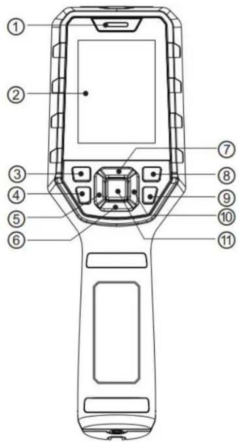
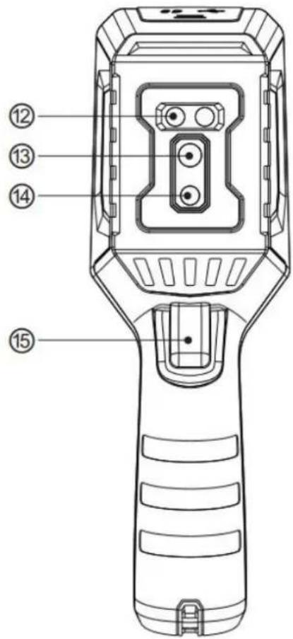
Figure 2-1: Instrument panel
Description:
| Num | Description | Num | Description |
| (1) | Indicator light | (9) | Key:Return key |
| (2) | Liquid crystal display | (10) | Key:Right key |
| (3) | Key:ON/OFF key | (11) | Key:SET key |
| (4) | Key:Lighting key | (12) | Lighting |
| (5) | Key:Left key | (13) | Infrared thermal image window |
| (6) | Key:Down key | (14) | Visible light camera window |
| (7) | Key:Up key | (15) | Camera Trigger key |
| (8) | Key:Photo browsing key |
3. How to Use the Thermal Imager
About This Chapter
This chapter introduces the thermal imager function and provides some basic examples of basic operations and how to use the menu.
Instrument Interface
The thermal imager interface:
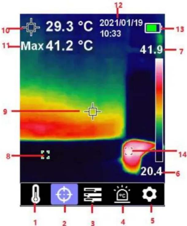
heatmap
| Time (hours) | Temperature (°C) | | ------------ | ---------------- | | 1 | 29.3 | | 2 | 41.2 | | 3 | 41.9 | | 4 | 20.4 | | 5 | 20.4 | | 6 | 20.4 | | 7 | 20.4 | | 8 | 20.4 | | 9 | 20.4 | | 10 | 20.4 | | 11 | 20.4 | | 12 | 20.4 | | 13 | 20.4 | | 14 | 20.4 |Figure 3-1: Thermal imager interface
Description:
| Num | Description | Num | Description |
| (1) | Temperature unit options | (8) | Current automatic tracking temperature minimum point |
| (2) | Cursor options | (9) | Temperature measurement central point |
| (3) | Palette options | (10) | Temperature measurement central point temperature |
| (4) | High and low temperature alarm options | (11) | Automatic tracking maximum temperature point display |
| (5) | Setting options | (12) | Current date and time |
| (6) | Current automatic tracking temperature minimum point temperature | (13) | Current battery level indication |
| (7) | Current automatic tracking temperature maximum point temperature | (14) | Current automatic tracking temperature maximum point |
Basic Operation
Photographing and Viewing
In the observation interface, briefly press the Trigger key to capture the picture; if automatic saving is turned off, press the Trigger key and press the > key to save or press the key to cancel saving. In the main interface, briefly press the key to enter the picture album to view the saved pictures.
Image Integration
The product can capture infrared images and display them in realtime; display the temperature of the measured target area on the LCD screen. If the integration function is needed, press > key to adjust the integration depth. The integration is divided into five levels: namely 0% (pure visible light), 25%, 50%, 75% and 100% (pure thermal image). The optimal integration distance is ≥ 1m. Press < / > key to adjust the integration depth, and the corresponding integration percentage prompt will also be displayed.
Torch
In the dark, press key to enable the torch to lighting. It is convenient to align the thermal imager to detect the object.
Switch between Celsius and Fahrenheit
-
On the main thermal imaging test interface, press key to enter the configuration main menu, and press key to select the temperature unit option.
-
Press key to enter the sub-menu configuration, press key to select the Celsius Fahrenheit units for switching, and press key to save the configuration.
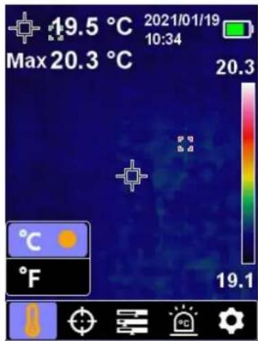
Central point/High and Low temperature tracking/Main temperature measurement area mode
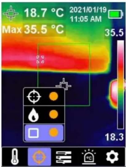
- On the main thermal imaging test interface, press key to enter the configuration main menu, and press / key to select the cursor option.
- Press SET key to select the option of ☐, and when the cross center appears, it indicates that the central point cursor is turned on.
- Press SET key to select the option of ⬆, and when the high and low temperature tracking function is turned on, the high and low temperature automatic tracking box appears in the thermal imaging screen.
- Press key to select the option of ☐. At this time, a green box is displayed in the center of the screen, indicating that temperature measurement of main area has been turned on(Note: when this function is turned on, the temperature measurement area is only in the green box.).
Palette Style Selection
-
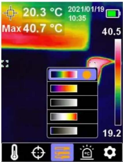
On the main thermal imaging test interface, press key to enter the configuration main menu, and press / key to select the palette option
-
Press key to enter sub-menu option, and select from iron red, rainbow, white heat, black heat and red heat by key. At this time, the thermal imaging will be displayed according to different pseudo colors.
-
Press key to return to the main interface of thermal imager.
High and Low Temperature Alarm
-
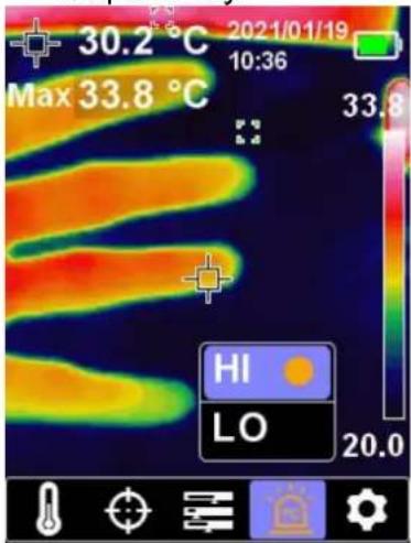
On the main thermal imaging test interface, press key to enter the configuration main menu, and press / key to select the High and low temperature alarm option.
-
Press key to enter the sub-menu option, and select the HI (High) or LO (Low) by A key, which can turn on and off the high temperature alarm and low temperature alarm simultaneously or respectively.
Setting Interface
-
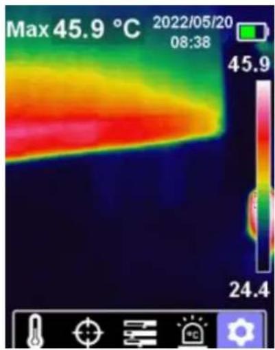
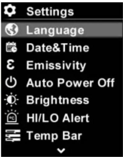
On the main thermal imaging test interface, press key to enter the configuration main menu, and press / > key to select the setting option
-
Press SET key to enter the secondary menu of the setting interface, and the language, automatic shutdown and other options can be set by / key.
4.Data Communication
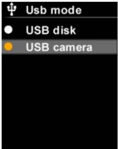
After entering the primary menu of the setting interface, select the USB mode option. USB has two modes.
-
USB flash disk: it is used to read the pictures in SD card through USB and connect the upper computer analysis software.
-
USB camera: it is a projection mode, in which the thermal image can be projected onto the display screen through USB.
Note:
- Please download the upper computer software and complete the installation.
- For the use method of upper computer software, please refer to the software user manual in the help option of the operation interface for the operation method.
- Special precautions: do not unplug the USB cable in USB communication, because the device and the computer have been successfully connected. If you want to disconnect the device, remove the computer connection correctly (select the device to be removed in the lower right corner of the computer).
- Please format the SD card before using the device for the first time.
5.General Specification
| Sensor | Non-refrigeration infrared focal plane thermal im sensor 120*90 |
| Pixel size | 17μm |
| Infrared spectral bandwidth | 8~14μm |
| Thermal imaging pixel | 10800 (120*90) |
| Thermal imaging sensitivity | ≤60mK |
| Field of View Angl (FOV) | 50° (H)*38° (V) |
| Instant Field of View Angle(IFOV) | 7.3mrad |
| Frame rate | ≤25Hz |
| Temperature range | -20°C ~400°C |
| Accuracy | -10°C ~400°C,the accuracy is ± 2C or 2%; ta maximum value (normal temperature 25 °C ) |
| Resolution ratio | 0.1°C |
| Temperature measurement response time | ≤500ms |
| Emissivity | 0.95(default) (adjustable from 0.1 to 0.99) |
| Temperature measurement display | Main area temperature measurement (ROI), cen point temperature measurement, high and low temperature tracking |
| Palette | Iron red, rainbow, white heat, black heat, red |
| Display type | 2.8" TFT LCD |
| Display resolution | 320*240 |
| Image format | BMP |
| Visible light lens | Yes |
| Visible light resolution | 640*480 |
| Field of View Angl (FOV) | 81 degree |
| Image mode | Thermal imaging, digital camera (visible band temperature display), integration |
| Thermostat alarm | Image alarm, LED alarm and buzzer alarm |
| PC analysis software | Yes |
| Data | Type-C USB |
| communication | |
| Battery | Li-ion 3.7V/5000mAh |
| Service time | Not less than 6 hours |
| Charging time | ≤ 5 hours |
| Charging voltage / current | 5V/2A |
| Image storage | Micro SD card |
| Drop test | 2m |
| IP level | IP54 |
| Storage temperature | -20 ~ 60°C (-4 ~ 140 °F) |
| Working temperature | 0 ~ 50°C (32 ~ 140 °F) |
| Working humidity | < 90%RH (non-condensing) |
6.Appendix
Appendix A: Common emissivity
The normal emissivity as shown in below:
| Material | Emissivity | Material | Emissivity |
| Wood | 0.85 | Black paper | 0.86 |
| Water | 0.96 | Polycarbonate | 0.8 |
| Brick | 0.75 | Concrete | 0.97 |
| Stainless steel | 0.14 | Copper oxide | 0.78 |
| Adhesive tape | 0.96 | Cast iron | 0.81 |
| Aluminum plate | 0.09 | Rust | 0.8 |
| Copper plate | 0.06 | Plaster | 0.75 |
| Black aluminum | 0.95 | Paint | 0.9 |
| Human skin | 0.98 | Rubber | 0.95 |
| Asphalt | 0.96 | Soil | 0.93 |
| PVC plastic | 0.93 |
Appendix B:Accessories
(The accessories subject to final delivery.)
Standard:
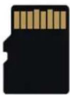
32G Memory card
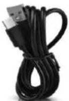
USB Line
User Manual
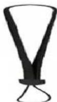
Rope
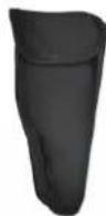
Bag
Appendix C: Maintenance and Cleaning
General maintenance
Do not store or place the instrument in a place where the LCD screen will be exposed to direct sunlight for a long time.
Caution: Do not let spray, liquid or solvent touch the instrument to prevent
damage to the instrument.
Cleaning:
Check the instrument frequently according to the operation. Clean the external surface of the instrument as follows:
- Please wipe the floating dust outside the instrument with a soft cloth. When cleaning the LCD, be careful not to scratch the transparent LCD protection screen.
- Wipe the instrument with a damp but non dripping soft cloth. Please disconnect the power supply. It can be scrubbed with soft detergent or water. Do not use any abrasive chemical cleaning agent to avoid damaging the instrument.

Warning: Please make sure the instrument is dry before re-energizing
to avoid electrical short circuit or personal injury caused by moisture.
- General Warranty
- Table of Contents
- Safety Information 2
- Instrument Panel 4
- How to Use the Thermal Imager 5
- 4.Data Communication 11
- 5.General Specification 12
- Appendix ......14
- Safety Information
- General Safety Requirements
- Safety Terms and Symbols
- Safety Terms
- Instrument Panel
- Panel and Keys
- How to Use the Thermal Imager
- About This Chapter
- Instrument Interface
- Basic Operation
- Photographing and Viewing
- Image Integration
- Torch
- Switch between Celsius and Fahrenheit
- Central point/High and Low temperature tracking/Main temperature measurement area mode
- Palette Style Selection
- High and Low Temperature Alarm
- Setting Interface
- 4.Data Communication
- Note:
- 6.Appendix
- Appendix A: Common emissivity
- Appendix B:Accessories
- Appendix C: Maintenance and Cleaning
- General maintenance
- Cleaning:
Brand : Owon
Model : TI219
Category : Thermometer