
WP-501 - Wall switch Kramer - Free user manual and instructions
Find the device manual for free WP-501 Kramer in PDF.


| Product Type | Wall Plate AV Controller and Switcher for simple room control and signal switching |
| Model | WP-501 |
| Brand | Kramer |
| Dimensions (WxDxH) | 16.2 cm x 3.6 cm x 11.4 cm (6.4" x 1.42" x 4.5") |
| Weight | Approx. 0.25 kg (0.55 lbs) |
| Power Source | 12V DC, 210mA (power supply included) |
| Inputs | 1 composite video (1Vpp/75Ω) on terminal block; 1 VGA (PC) on terminal block; 1 VGA (PC) on 15-pin HD; 2 unbalanced stereo audio (3-pin terminal block and 3.5mm mini jack); 1 microphone (condenser/dynamic) on 3.5mm mini jack |
| Outputs | 1 VIDEO OUT on 2-pin terminal block; 2 Audio OUT unbalanced stereo on 3-pin terminal block; 1 VGA (PC) OUTPUT on 10-pin terminal block; 2 relays on 3-pin terminal block |
| Control Ports | Ethernet, IR out on terminal block, RS-232 on terminal block, USB connector |
| Default IP Address | 192.168.1.39 (mask 255.255.0.0, gateway 0.0.0.0) |
| Supported RS-232 Baud Rates | 1200, 2400, 4800, 9600, 19200, 38400, 57600, 115200 |
| Default EDID | Supports standard timings up to 1600x1200@60Hz; native 1024x768@60Hz (4:3) |
| Front Panel Buttons | 4 configurable backlit buttons (ON/OFF, PC1, PC2, VIDEO) for source selection and projector control |
| Volume Controls | Two analog knobs: one for PC/Video audio, one for microphone level |
| Microphone Mode Switch | Dynamic or condenser, located behind front panel (default dynamic) |
| Relay Ports | 2 relays on terminal blocks for controlling room items (e.g., screen, drapes) |
| Software Support | Kramer K-Config for configuration, Kramer Site-CTRL for network management |
| Included Accessories | Screwdriver, power supply, user manual |
| Optional Accessories | USB cable (C-UA/MUB-3), WP-501 installation cable, Site-CTRL Management Tool Software |
| Care and Cleaning | No user serviceable parts; use only provided power supply; avoid exposure to moisture, excessive sunlight, and dust |
| Safety Warnings | Disconnect power before opening or servicing; grounding recommended; use only Kramer supplied power adapter |
| Repairability | Service only by authorized Kramer technicians; seven-year warranty on parts and labor |
| Mounting | 3-gang USA wall plate |
Frequently Asked Questions - WP-501 Kramer
User questions about WP-501 Kramer
0 question about this device. Answer the ones you know or ask your own.
Ask a new question about this device
Download the instructions for your Wall switch in PDF format for free! Find your manual WP-501 - Kramer and take your electronic device back in hand. On this page are published all the documents necessary for the use of your device. WP-501 by Kramer.
USER MANUAL WP-501 Kramer
Wall Plate Solution for Simple Room Control and Signal Switching
Contents
1 Introduction 1
2 Getting Started 2
2.1 Achieving the Best Performance 2
3 Overview 3
4 Defining the WP-501 4
4.1 Grounding the WP-501 6
5 Using Your WP-501 7
5.1 Set the WP-501 8
5.2 Connecting the WP-501 9
5.3 Operating the WP-501 11
6 Technical Specifications 12
Figures
Figure 1: WP-501 Front Panel 4
Figure 2: WP-501 Rear Panel 5
Figure 3: Grounding Connection Components 6
Figure 4: The Setup Internal Panel 8
Figure 5: Connecting the WP-501 Front Panel 9
Figure 6: Connecting the WP-501 Rear Panel 10
1 Introduction
Welcome to Kramer Electronics! Since 1981, Kramer Electronics has been providing a world of unique, creative, and affordable solutions to the vast range of problems that confront the video, audio, presentation, and broadcasting professional on a daily basis. In recent years, we have redesigned and upgraded most of our line, making the best even better!
Our 1,000-plus different models now appear in 11 groups that are clearly defined by function: GROUP 1: Distribution Amplifiers; GROUP 2: Switchers and Matrix Switchers; GROUP 3: Control Systems; GROUP 4: Format/Standards Converters; GROUP 5: Range Extenders and Repeaters; GROUP 6: Specialty AV Products; GROUP 7: Scan Converters and Scalers; GROUP 8: Cables and Connectors; GROUP 9: Room Connectivity; GROUP 10: Accessories and Rack Adapters; GROUP 11: Sierra Products
Congratulations on purchasing your Kramer WP-501 Wall Plate Solution for Simple Room Control and Signal Switching that can be used as a projector switcher and controller in the classroom.
The package includes the following items:
WP-501
- Screwdriver
- Power supply
- This user manual
2 Getting Started

This user manual is written for the end user. Refer to the separate Kramer K-Config Guide (available online) for details of how to install and configure the Room Controller.
We recommend that you:
- Unpack the equipment carefully and save the original box and packaging materials for possible future shipment
• Review the contents of this user manual
• Use Kramer high performance high resolution cables
• Use only the power cord that is supplied with this machine

Go to http://www.kramerelectronics.com to check for up-to-date user manuals, application programs, and to check if firmware upgrades are available (where appropriate).
2.1 Achieving the Best Performance
To achieve the best performance:
- Use only good quality connection cables to avoid interference, deterioration in signal quality due to poor matching, and elevated noise levels (often associated with low quality cables)
- Avoid interference from neighboring electrical appliances that may adversely influence signal quality
- Position your Kramer WP-501 away from moisture, excessive sunlight and dust

Caution: No operator serviceable parts inside the unit
Warning: Use only the Kramer Electronics input power wall adapter that is provided with the unit
Warning: Disconnect the power and unplug the unit from the wall before installing
3 Overview
The WP-501 is an all-in-one AV solution for classrooms, training rooms and similar simple AV installations. It enables remote projector or flat panel control and the routing of one of three A/V sources to the inputs of a display device via the front panel buttons. The WP-501:
- Consists of two VGA inputs, each with an unbalanced stereo audio signal (one on the front panel and the other on the rear panel), one composite video input (on the rear panel) with an unbalanced stereo audio signal, and a dynamic or condenser microphone input
- Includes an RGBHV output, a composite video output and two identical audio outputs
- Includes bidirectional RS-232 and IR out for controlling the display device
- Has two relay ports for control of other room items related to the AV system such as raising and lowering drapes, the screen or the projector
- Has two analog volume control adjustment knobs, one for the selected PC/Video audio signal and the other for microphone volume adjustment
- Features four dedicated front panel buttons, one for turning the projector ON/OFF and the other three for selecting which input to route to the projector. Each button can be programmed to perform command macros
- Is Kramer Site-CTRL™ compatible, for network remote control and management over the Ethernet port
Kramer Site-CTRL is a powerful A/V asset management tool. It offers real-time network monitoring and control of Kramer Master controllers installed at an A/V site and all the connected A/V equipment. The Kramer Site-CTRL downloadable version can monitor and control up to 100 Kramer Master controllers. For larger installations, a similar solution is also available
- Includes an Ethernet port for remote control and management from the Kramer Site-CTRL™ software and for accessing the stored Web pages
- Can store EDID information and support EDID communication with the connected PC sources (the default EDID is already uploaded upon delivery); a specific EDID can be uploaded via the Kramer K-Config software
- Has a USB port for programming via a computer
• Is available worldwide as a 3 Gang USA wall plate
4 Defining the WP-501
This section defines the WP-501.

Figure 1: WP-501 Front Panel
| # | Feature Function | |||
| 1 | VOLUME MIC Adjustment Knob | Rotate clockwise to increase the microphone level | ||
| 2 | MIC IN 3.5mm mini jack | Connect to microphone | ||
| 3 | PC 1 15-Pin HD Connector | Connect to the PC 1 source (pins ED12 and ED15 pass the EDID information) | ||
| 4 | AUDIO 1 3.5mm mini jack | Connect to the unbalanced stereo audio signal of the PC1 source | ||
| 5 | VOLUME PC/VIDEO Adjustment Knob | Rotate clockwise to increase the PC or video audio level | ||
| 6 | SELECT Buttons | ON/OFF Toggle | to turn the projector on/off | These four configurable backlit buttons can set up any supported command, as configured by the system integrator |
| 7 | PC 1 Select PC | 1 as the source | ||
| 8 | PC 2 Select PC | 2 as the source | ||
| 9 | VIDEO (CV) | Select composite video as the source | ||

Figure 2: WP-501 Rear Panel
| # Feature Function | |||
| 1 | IR OUT | Controls the display device via an IR emitter (for example, in cases where RS-232 control is not available) | |
| 2 | VIDEO OUT Connect to the video IN of the display device | ||
| 3 | AUDIO OUT 2 | Connect to the audio input associated with the Video Input channel of the display deviceIdentical to the AUDIO OUT 1 port | |
| 4 | AUDIO OUT 1 Connect to the audio input associated with the PC graphics Input channel of the display deviceIdentical to the AUDIO OUT 2 port | ||
| 5 | POWER + 12V DC Connect to power the unit | ||
| 6 | Ring Tongue Terminal Grounding Screw | Connect to grounding wire (optional), (see Section 4.1) | |
| 7 | ETHERNET Port | Connect to the local computer network for accessing the stored Web pages, for remote control and management from the Kramer Site-CTRL software and for remote configuration file and firmware updates upload | |
| 8 | RELAYS Terminal Blocks | Connect to low-voltage relay-driven devices (from 1 to 2) | |
| 9 | VGA (PC) OUTPUT Terminal Blocks | Connect to the PC graphics IN of the display device | |
| 10 | RS-232 Port | Connect to the RS-232 connector on the display device | |
| 11 | PC 2 IN Terminal Blocks | Connect to the PC 2 source (pins ED12 and ED15 pass the EDID information)Make sure you use 15-wire VGA cables between the WP-501 and the PC2 to enable EDID communication | |
| 12 | AUDIO IN 2 Terminal Blocks | Connect to the unbalanced stereo audio signal of the PC2 source | |
| 13 | AUDIO/VIDEO | VIDEO | Connect to the composite video source |
| 14 | IN Terminal Blocks | RIGHT | Connect to the left and right unbalanced audio source |
4.1 Grounding the WP-501
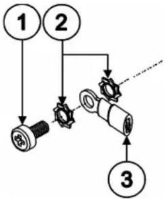
The grounding screw is used to earth the chassis of the unit to the building ground preventing static electricity from impacting the performance of the unit.
This section defines the grounding screw components.
flowchart
graph TD
    A["1"] --> B["2"]
    B --> C["3"]
    C --> D["4"]
    D --> E["5"]
    E --> F["6"]
    F --> G["7"]
    G --> H["8"]
    H --> I["9"]
    I --> J["10"]
| # Component Description |
| 1 M3X6 screw |
| 2 1/8" Toothed Lock Washer |
| 3 M3 Ring Tongue Terminal |
Figure 3: Grounding Connection Components
To ground the WP-501:
- Connect the Ring Tongue terminal to the building grounding point wire (it is recommended to use a green-yellow AWG#18 (0.82mm^2) wire, crimped with a proper hand-tool).
- Insert the M3x6 screw through the toothed lock washers and the tongue terminal in the order shown above.
- Insert the M3x6 screw (with the two toothed lock washers and ring tongue terminal) into the grounding screw hole and tighten the screw.
5 Using Your WP-501
This user manual is applicable once the unit is installed and configured by authorized Kramer technical personnel or by an external system integrator. The installation process is not detailed in this user manual, and includes configuration via the Kramer K-Config Windows®-based configuration software.
This section describes how to:
• Setup the WP-501 (see Section 5.1)
- Connect the WP-501 (see Section 5.2)
• Control the WP-501 (see Section 5.3)
5.1 Set the WP-501
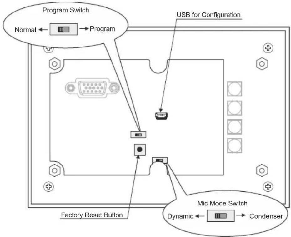
Before installing the front panel and mounting it on the wall, you need to setup the WP-501. This section defines the relevant internal panel components, viewed from the front panel side:
flowchart
graph TD
    A["Program Switch"] --> B["Normal"]
    B --> C["Program"]
    C --> D["Factory Reset Button"]
    D --> E["Micro Mode Switch"]
    E --> F["Condenser"]
    style A fill:#f9f,stroke:#333
    style B fill:#ccf,stroke:#333
    style C fill:#cfc,stroke:#333
    style D fill:#fcc,stroke:#333
    style E fill:#cff,stroke:#333
    style F fill:#ffc,stroke:#333
Figure 4: The Setup Internal Panel
| Feature Function | ||
| Program Switch For firmware upgrade | ||
| USB port for configuration | Use the USB port to configure the unit (for system integrator) | |
| Mic Mode Switch | Set the microphone mode switch to dynamic or condenser (by default, this switch is set to dynamic).It is recommended to set the mic mode switch before mounting the WP-501 front panel (see Section 5.2.1) | |
| Factory Reset ButtonIP Address: 192.168.1.39Mask: 255.255.0.0Gateway: 0.0.0.0 | Disconnect the power and then connect it while pressing the Factory Reset button (using a small screwdriver). The unit will power up and load its memory with the factory default definitions | |
 | This operation should be carried out byauthorized Kramer technical personnel or by an external system integrator, and requires removal of the device from the wall byunscrewing the four wall mount screws | |
5.2 Connecting the WP-501
To connect the WP-501, as illustrated in the example in Figure 5 (front panel) and Figure 6 (rear panel), do the following:
-
On the front panel, connect:
-
A computer graphics source and the audio source of the computer to the PC 1 15-pin HD and 3.5mm mini jack, respectively
A microphone to the MIC IN 3.5mm mini jack (see Section 5.2.1)

flowchart
graph TD
    A["Computer Graphics Source"] -->|VGA + Audio| B["Screen"]
    A -->|CV| C["DVD Player"]
    A -->|Audio| D["Projector"]
    B -->|VGA - RCP1| E["Power"]
    B -->|VGA + Audio| F["Microcontroller"]
    B -->|IR| G["Radio"]
    B -->|VGA - RCP2| H["Audio"]
    B -->|VGA + Audio| I["Video"]
    C --> J["Computer Graphics Source"]
    D --> K["Computer Graphics Source"]
    E --> L["Monitor"]
    F --> M["Monitor"]
    G --> N["Monitor"]
    H --> O["Monitor"]
    I --> P["Monitor"]
Figure 5: Connecting the WP-501 Front Panel
- On the rear panel, connect:
A computer graphics source and the audio source of the computer to the PC 2 IN and AUDIO IN 2 terminal block connectors, respectively
A composite video source (for example, a DVD player) and the audio source of that composite video source to the rear panel AUDIO/VIDEO IN Terminal block connectors, respectively
-
On the rear panel, connect the display device (for example, a projector) as follows. Connect the:
-
VGA (PC) OUTPUT to the PC Graphics (15-pin HD connector or RGBHV connector) input on the projector
■ VIDEO OUT output (VIDEO OUT, GND) to the video input on the projector - AUDIO OUT 1 and AUDIO OUT 2 outputs to the audio input of the video and PC inputs on the projector
You can connect either AUDIO OUT 1 or AUDIO OUT 2 to either the PC or the CV input of the projector since both audio outputs are identical
■ RS-232 port to the PC control port of the projector and/or the IR OUT to the IR receiver of the projector
- Connect the relay terminal block connectors to the screen.
- Connect the ETHERNET port to a PC for configuration and control (not shown in Figure 6), see Section 5.3.

Figure 6: Connecting the WP-501 Rear Panel
5.2.1 Connecting the Microphone
You can connect either a dynamic or a condenser microphone to the MIC IN 3.5mm mini jack. Before connecting the microphone, set the microphone mode switch to dynamic or condenser (by default, this switch is set to dynamic). The Dyn/Cond mode switch is located behind the front panel on the lower left side of the MIC IN 3.5mm jack, as illustrated in Figure 4.
It is recommended to set the mic mode switch before mounting the WP-501 front panel.

When disconnecting the microphone or switching it OFF, turn the microphone volume adjustment knob to the left (MIC mute).
When using the microphone, pay attention to the placement of the speakers. By placing the speakers properly, the chance of getting audio feedback is minimized.
5.3 Operating the WP-501
The Ethernet and/or USB ports are used by the technical installer to configure the WP-501 front panel SELECT buttons to set a sequence of actions in a trigger (a macro) and assign them to any of the buttons, such as those defined in the following example. Pressing a button initiates a trigger, during which the button blinks (as programmed by the system integrator).
| The Label | Macro Sequence Example |
| ON/OFF | Power up/Power down the projector (this is a 2-toggle button)1 minute delay [for the projector to heat up]Set required Audio level for the projectorThe projector selects the PC input |
| PC 1 (switch to PC1 on WP-501) | Select the PC 1 input of the projectorStop the DVD playerPower down the DVD player |
| PC 2 (switch to PC1 on WP-501) | Select the PC 1 input of the projectorStop the video player |
| VIDEO (CV) | Select the VIDEO (CV) inputThe projector selects the DVD inputPlay the DVD |
In addition to operation via the front panel buttons, you can monitor the WP-501 via the Ethernet, using Site-CTRL™ and the stored Web pages. You can also load EDID data via the Kramer K-Config software.
6 Technical Specifications
| INPUTS: | 1 composite video (1Vpp/75Ω) on 2-pin terminal block connectors1 unbalanced audio on 3-pin terminal block connectors1 VGA (PC) on 11-pin terminal block connectors (including EDID pins)1 stereo analog audio on 3-pin terminal block connectors1 VGA (PC) on a 15-pin HD connector (including EDID pins)1 stereo analog audio on a 3.5mm mini connector1 condenser/dynamic microphone on a 3.5mm mini connector |
| OUTPUTS (on Terminal Block Connectors): | 1 VIDEO OUT on 2-pin terminal block connectors2 Audio OUT unbalanced stereo audio on 3-pin terminal block connectors1 VGA (PC) OUTPUT on 10-pin terminal block connectors2 relays on 3-pin terminal block connectors |
| PORTS: | Ethernet, 1 IR out on terminal block connectors, 1 RS-232 on terminal block connectors, 1 USB connector |
| DEFAULT IP ADDRESS | 192.168.1.39 |
| SUPPORTED BAUD RATES FOR RS-232: | 1200, 2400, 4800, 9600, 19200, 38400, 57600, 115200 |
| DEFAULT EDID INFORMATION: | Standard timings supported: 640x480px60Hz (IBM VGA), 640x480px67Hz (Apple Mac II), 640x480px72Hz (VESA), 640x480px75Hz (VESA), 800x600px56Hz (VESA), 800x 600px60Hz (VESA), 800x600px72Hz (VESA), 800x600px75Hz (VESA), 1024x768px60Hz (Native/preferred timing (4:3)) (VESA), 1024x768px70Hz (VESA), 1024x768px75Hz (VESA), 1280x1024px75Hz (VESA), 1280x1024px60Hz (VESA STD), 1280x960px60Hz (VESA STD), 1400x1050px60Hz (VESA STD), 1440x900px60Hz (VESA STD), 1600x1200px60Hz (VESA STD) |
| POWER SOURCE: | 12V DC, 210mA |
| DIMENSIONS: | 16.2cm x 3.6 cm x 11.4cm (6.4" x 1.42" x 4.5", W, D, H) |
| WEIGHT: | 0.25 kg (0.55lbs) approx. |
| ACCESSORIES: | 12V DC, 0.5A power supply, screwdriver |
| OPTIONS: | USB cable 3' (0.91m) (Part number C-UA/MUB-3),WP-501 Installation cable, Site-CTRLTM Management Tool Software |
| Specifications are subject to change without notice at http://www.kramerelectronics.com | |
LIMITED WARRANTY
We warrant this product free from defects in material and workmanship under the following terms.
HOW LONG IS THE WARRANTY
Labor and parts are warranted for seven years from the date of the first customer purchase.
WHO IS PROTECTED?
Only the first purchase customer may enforce this warranty.
WHAT IS COVERED AND WHAT IS NOT COVERED
Except as below, this warranty covers all defects in material or workmanship in this product. The following are no covered by the warranty:
- Any product which is not distributed by us or which is not purchased from an authorized Kramer dealer. If you are uncertain as to whether a dealer is authorized, please contact Kramer at one of the agents listed in the Web site www.kramerelectronics.com.
- Any product, on which the serial number has been defaced, modified or removed, or on which the WARRANTY VOID IF TAAMERED, destroyed as being wise, interfered with.
- Damage, deterioration or malfunction resulting from:
i) Accident, misuse, abuse, neglect, fire, water, lightning or other acts of nature
ii) Product modification, or failure to follow instructions supplied with the product
iii) Repair or attempted repair by anyone not authorized by Kramer
iv) Any shipment of the product (claims must be presented to the carrier)
v) Removal or installation of the product
vi) Any other cause, which does not relate to a product defect
vii) Cartons, equipment enclosures, cables or accessories used in conjunction with the product
WHAT WE WILL PAY FOR AND WHAT WE WILL NOT PAY FOR
We will pay labor and material expenses for covered items. We will not pay for the following:
- Removal or installations charges.
- Costs of initial technical adjustments (set-up), including adjustment of user controls or programming. These costs are the responsibility of the Kramer dealer from whom the product was purchased.
- Shipping charges.
HOW YOU CAN GET WARRANTY SERVICE
- To obtain service on you product, you must take or ship it prepaid to any authorized Kramer service center.
- Whenever warranty service is required, the original dated invoice (or a copy) must be presented as proof of warranty coverage, and should be included in any shipment of the product. Please also include in any mailing a contact name, company, address, and a description of the problem(s).
- For the name of the nearest Kramer authorized service center, consult your authorized dealer.
LIMITATION OF IMPLIED WARRANTIES
All implied warranties, including warranties of merchantability and fitness for a particular purpose, are limited in duration to the length of this warranty.
EXCLUSION OF DAMAGES
The liability of Kramer for any effective products is limited to the repair or replacement of the product at our option. Kramer shall not be liable for:
- Damage to other property caused by defects in this product, damages based upon inconvenience, loss of use of the product, loss of time, commercial loss; or:
- Any other damages, whether incidental, consequential or otherwise. Some countries may not allow limitations on how long an implied warranty lasts and/or do not allow the exclusion or limitation of incidental or consequential damages, so the above limitations and exclusions may not apply to you.
This warranty gives you specific legal rights, and you may also have other rights, which vary from place to place.
NOTE: All products returned to Kramer for service must have prior approval. This may be obtained from your dealer.
This equipment has been tested to determine compliance with the requirements of:
EN-50081: "Electromagnetic compatibility (EMC);
generic emission standard.
Residential, commercial and light industry"
EN-50082: "Electromagnetic compatibility (EMC) generic immunity standard.
Part 1: Residential, commercial and light industry environment".
CFR-47: FCC* Rules and Regulations:
Part 15: "Radio frequency devices
Subpart B Unintentional radiators"
CAUTION!
Servicing the machines can only be done by an authorized Kramer technician. Any user who makes changes or modifications to the unit without the expressed approval of the manufacturer will void user authority to operate the equipment.
Use the supplied DC power supply to feed power to the machine.
Please use recommended interconnection cables to connect the machine to other components.
* FCC and CE approved using STP cable (for twisted pair products)

For the latest information on our products and a list of Kramer distributors, visit our Web site where updates to this user manual may be found.
We welcome your questions, comments, and feedback.
Web site: www.kramerelectronics.com
E-mail: info@kramerel.com



SAFETY WARNING
Disconnect the unit from the power supply before opening and servicing
- Contents
- Figures
- Introduction
- Getting Started
- Achieving the Best Performance
- Overview
- Defining the WP-501
- Grounding the WP-501
- Using Your WP-501
- Set the WP-501
- Connecting the WP-501
- Connecting the Microphone
- Operating the WP-501
- Technical Specifications
- LIMITED WARRANTY
- HOW LONG IS THE WARRANTY
- WHO IS PROTECTED?
- WHAT IS COVERED AND WHAT IS NOT COVERED
- WHAT WE WILL PAY FOR AND WHAT WE WILL NOT PAY FOR
- HOW YOU CAN GET WARRANTY SERVICE
- LIMITATION OF IMPLIED WARRANTIES
- EXCLUSION OF DAMAGES
- CAUTION!
- SAFETY WARNING
Brand : Kramer
Model : WP-501
Category : Wall switch