SP-10D - Audiovisual Equipment Kramer - Free user manual and instructions
Find the device manual for free SP-10D Kramer in PDF.


| Product Type | Digital Video Processor (ProcAmp, TBC, Format Converter, Standards Converter) |
| Dimensions (W x D x H) | 19" x 7" x 1U (483mm x 178mm x 44mm), rack-mountable |
| Weight | 2.6 kg (5.7 lbs) approx. |
| Power Supply | Universal AC, 100-240V, 50/60Hz, 27VA |
| Video Standards | PAL-B/D/G/H/I/M/N, NTSC-3.58/4.43, SECAM |
| Digital Processing | 10-bit, 4-field memory |
| Inputs | 1x composite (BNC), 1x Y/C (4-pin), 1x component YUV/RGB/S (BNC), 1x genlock (BNC, loopable) |
| Outputs | 1x composite (BNC), 1x Y/C (4-pin), 1x component YUV/RGsB/RGBS/RGBHV (BNC), 1x splitter (BNC), 1x genlock loop (BNC) |
| Bandwidth (-3dB) | 5 MHz |
| Diff. Gain / Diff. Phase | 1% / 1° |
| S/N Ratio | 60 dB |
| K-Factor / Luma Non-Linearity | 0.4% / 1% |
| Chroma/Luma Delay | <15 ns |
| Controls | Front panel buttons & 7-segment display; RS-232 serial port |
| Memory Setups | 16 non-volatile setups for storing/recalling configurations |
| ProcAmp Functions | Video gain, brightness, contrast, color, hue, vertical & horizontal sharpness, H/V shift, SCH phase, delay |
| Color Control | Independent RGB and YUV color spaces, color space selection (off, YUV, RGB) |
| Additional Features | Genlock with H-delay and SCH, freeze frame, before/after split-screen, panel lock, power-down save, automatic input detection (AUTO) |
| Test Signals | VITS 330, 18, 17; split 75% bar, vertical/horizontal/inverse bar generators (via DIP-switches) |
| Accessories Included | Power cord, null-modem adapter |
| Warranty | 7 years (labor and parts) from first customer purchase |
Frequently Asked Questions - SP-10D Kramer
User questions about SP-10D Kramer
0 question about this device. Answer the ones you know or ask your own.
Ask a new question about this device
Download the instructions for your Audiovisual Equipment in PDF format for free! Find your manual SP-10D - Kramer and take your electronic device back in hand. On this page are published all the documents necessary for the use of your device. SP-10D by Kramer.
USER MANUAL SP-10D Kramer
Kramer Electronics, Ltd.

USER MANUAL
Model:
SP-10D
Digital Video Processor
Contents
1 Introduction 1
2 Getting Started 1
2.1 Quick Start 2
3 Overview 3
4 Your SP-10D Digital Video Processor 4
5 Installing the SP-10D in a Rack 8
6 Connecting Your SP-10D Digital Video Processor 9
6.1 Connecting a PC 10
6.2 DIP-Switch Settings 11
7 Operating the SP-10D Digital Video Processor 12
7.1 Storing and Recalling Setups 14
7.2 Locking the Front Panel 14
8 Technical Specifications 15
9 Communication Protocol 16
Figures
Figure 1: SP-10D Digital Video Processor 5
Figure 2: Connecting the SP-10D Digital Video Processor 10
Figure 3: Crossed Cable RS-232 Connection 11
Figure 4: Straight Cable RS-232 Connection with a Null Modem Adapter 11
Tables
Table 1: Front Panel SP-10D Digital Video Processor 6
Table 2: Rear Panel SP-10D Digital Video Processor 7
Table 3: DIP-switch Settings 11
Table 4: Test Signals 12
Table 5: Technical Specifications of the SP-10D Digital Video Processor 15
Table 6: Protocol Definitions 16
1 Introduction
Welcome to Kramer Electronics! Since 1981, Kramer Electronics has been providing a world of unique, creative, and affordable solutions to the vast range of problems that confront the video, audio, presentation, and broadcasting professional on a daily basis. In recent years, we have redesigned and upgraded most of our line, making the best even better! Our 1,000-plus different models now appear in 11 groups ^1 that are clearly defined by function.
Thank you for purchasing your Kramer SP-10D Digital Video Processor. This product is ideal for:
• Video broadcasting and editing studios
- All postproduction uses
- Presentation applications for multi-standard/multi-format sources use
The package includes the following items:
• SP-10D Digital Video Processor
- Null-modem adapter
- Power cord ^2
- This user manual ^3
2 Getting Started
We recommend that you:
- Unpack the equipment carefully and save the original box and packaging materials for possible future shipment
- Review the contents of this user manual
- Use Kramer high performance high-resolution cables ^4
2.1 Quick Start
This quick start chart summarizes the basic setup and operation steps.
Step 1: Mount the machine - see section 5
Mount the machine in a rack or stick the 4 rubber feet to the underside

Step 2: Connect the Inputs and outputs - see section 6

flowchart
graph TD
    A["Server"] -->|Connect the inputs| B["Composite Video Player"]
    A -->|Connect the outputs| C["s-Video Player"]
    A -->|Connect the genlock| D["Video Player (Y, R-Y, B-Y Source)"]
    A -->|Connect a PC controller| E["Camera (RGBS Source)"]
    A -->|Next Genlocked Unit| F["Genlock Source"]
    A --> G["Composite Video Display (showing sp8 image)"]
    A --> H["Composite Video Display"]
    A --> I["Plasma Display"]
    A --> J["Computer"]
    style A fill:#f9f,stroke:#333
    style B fill:#ccf,stroke:#333
    style C fill:#ccf,stroke:#333
    style D fill:#ccf,stroke:#333
    style E fill:#ccf,stroke:#333
    style F fill:#ccf,stroke:#333
    style G fill:#ccf,stroke:#333
    style H fill:#ccf,stroke:#333
    style I fill:#ccf,stroke:#333
    style J fill:#ccf,stroke:#333
Step 3: SET the DIP-switches - see section 6.2
Step 4: Turn the power ON
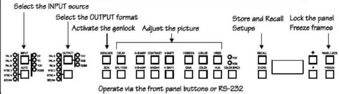
Step 5: Operate the machine - see section 7
flowchart
graph TD
    A["Select the INPUT source"] --> B["SELECT OUTPUT FORMAT"]
    B --> C["Activate the genlock"]
    C --> D["Adjust the picture"]
    D --> E["Store and Recall"]
    E --> F["Lock the panel"]
    F --> G["Recall"]
    G --> H["+"]
    H --> I["PANELLOCK"]
    B --> J["GENLOCK"]
    J --> K["DELAY"]
    K --> L["H-SHARP"]
    L --> M["CONTRAST"]
    M --> N["V-SHIFT"]
    N --> O["VGREEN"]
    O --> P["LUSLUE"]
    P --> Q["VRED"]
    Q --> R["YUV"]
    R --> S["RECALL"]
    S --> T["STORE"]
    T --> U["+"]
    U --> V["PANELLOCK"]
    style A fill:#f9f,stroke:#333
    style B fill:#ccf,stroke:#333
    style C fill:#cfc,stroke:#333
    style D fill:#fcc,stroke:#333
    style E fill:#ffc,stroke:#333
    style F fill:#fcc,stroke:#333
    style G fill:#fcf,stroke:#333
    style H fill:#cff,stroke:#333
    style I fill:#ffc,stroke:#333
    style J fill:#cfc,stroke:#333
    style K fill:#cfc,stroke:#333
    style L fill:#cfc,stroke:#333
    style M fill:#cfc,stroke:#333
    style N fill:#cfc,stroke:#333
    style O fill:#cfc,stroke:#333
    style P fill:#cfc,stroke:#333
    style Q fill:#cfc,stroke:#333
    style R fill:#cfc,stroke:#333
    style S fill:#cfc,stroke:#333
    style T fill:#cfc,stroke:#333
    style U fill:#cfc,stroke:#333
3 Overview
The unique SP-10D is a multi-standard/multi-format broadcast quality video processor – ProcAmp, TBC, format converter (for mixing different types of equipment), and standards converter. It is a universal single-box solution for all your video processing requirements.
In particular, the SP-10D Digital Video Processor includes the following:
- Inputs: composite video, s-Video, component video (YUV or RGB/S), and genlock
- Outputs ^1 : composite video, s-Video, component video (YUV, RGsB, RGBS, RGBHV), “before/after” split-screen, and genlock loop
• Video Standards ^2 : PAL-B/D/G/H/I/M/N, NTSC-3.58/4.43, SECAM - ProcAmp functions: video gain, brightness, contrast, color, hue, and sharpness (independent H and V)
- A full range of color control features in both YUV and RGB color spaces ^3
- Four-field memory for the highest picture quality
- Timing: genlocked to an external video reference with control of H-delay and SCH phase. Alternatively, the unit can synthesize its own timing to provide a full time-base-corrected (TBC) output
- Individual H and V Chroma – Luma delay
In addition, the SP-10D Digital Video Processor includes:
• 16 non-volatile memory setups that are available for saving the settings
- Power-down save, picture freeze, and a screen splitter that provides simultaneous "before and after" image comparison on one monitor
- Full 10-bit digital processing throughout, for the highest possible video quality
Control the SP-10D:
- Using the front panel buttons and the 7-segment display
- Remotely, by RS-232 serial commands transmitted by a touch screen system, PC, or other serial controller
To achieve the best performance:
- Connect only good quality connection cables, thus avoiding interference, deterioration in signal quality due to poor matching, and elevated noise levels (often associated with low quality cables)
- Avoid interference from neighboring electrical appliances that may adversely influence signal quality and position your Kramer SP-10D away from moisture, excessive sunlight and dust
4 Your SP-10D Digital Video Processor
Figure 1, Table 1, and Table 2 define the SP-10D Digital Video Processor.
Your SP-10D Digital Video Processor

flowchart
graph TD
    subgraph Power
        A["POWER"] --> B["2"]
        B --> C["3"]
        C --> D["4"]
        D --> E["5"]
        E --> F["6"]
        F --> G["7"]
        G --> H["8"]
        H --> I["9"]
        I --> J["10"]
        J --> K["11"]
        K --> L["12"]
        L --> M["13"]
        M --> N["14"]
        N --> O["15"]
        O --> P["16"]
        P --> Q["17"]
        Q --> R["18"]
        R --> S["19"]
        S --> T["20"]
        T --> U["21"]
        U --> V["22"]
        V --> W["23"]
        W --> X["24"]
        X --> Y["25"]
        Y --> Z["26"]
        Z --> AA["27"]
        AA --> AB["28"]
        AB --> AC["29"]
        AC --> AD["30"]
        AD --> AE["31"]
        AE --> AF["32"]
        AF --> AG["33"]
        AG --> AH["34"]
    end

    subgraph Digital Video Processor
        AI["SP-10D"] --> AJ["35"]
        AJ --> AK["36"]
        AK --> AL["37"]
        AL --> AM["38"]
        AM --> AN["39"]
        AN --> AO["40"]
        AO --> AP["41"]
        AP --> AQ["42"]
        AQ --> AR["43"]
        AR --> AS["44"]
        AS --> AT["45"]
        AT --> AU["46"]
        AU --> AV["47"]
        AV --> AW["48"]
        AW --> AX["49"]
        AX --> AY["50"]
        AY --> AZ["51"]
        AZ --> BA["52"]
        BA --> BB["53"]
        BB --> BC["54"]

    end

    subgraph Outputs
        AD["OUTPUTS"] --> AE
    end

    subgraph RS-232
        AR["RS-232"] --> AS
    end

    subgraph Setup
        AS --> AC
    end

    subgraph Control
        AD --> AD
    end
Figure 1: SP-10D Digital Video Processor

Table 1: Front Panel SP-10D Digital Video Processor
| # | Feature Function | |
| 1 | POWER Switch | Illuminated switch for turning the unit ON or OFF |
| 2 | INPUT STANDARD LEDs | Cycle between PAL B, PAL N, PAL M, NTSC 3, NTSC 4, and SECAM. The corresponding LED lights |
| 3 | INPUT Selector Button | Press to select the source, illuminating the appropriate LED |
| 4 | INPUT LEDs | Cycle between the video sources: CV, YC, YUV, and RGB/S. The corresponding LED lights |
| 5 | AUTO Button | Toggles between automatically recognizing the input standard (lighting the appropriate LED) and the manual selection mode |
| 6 | OUTPUT STANDARD LEDs | Cycle between PAL B, PAL N, PAL M, NTSC 3, NTSC 4, and SECAM. The corresponding LED lights |
| 7 | (COMPONENT) OUTPUT Button | Selects the component video output signal |
| 8 | COMPONENT OUTPUT LEDs | Cycle between YUV, RGB, and RGBS. The corresponding LED lights |
| 9 | STANDARDS Button Selects the output video standard | |
| 10 | SCH Button | Press the SCH button and adjust the subcarrier to horizontal phase relative to the genlock source, using the + and - buttons |
| 11 | GENLOCK Button | Press to enable GENLOCK operation |
| 12 | SPLITTER Button | Press the SPLITTER button and adjust the position of the boundary between the edited image and the original image, using the + and - buttons |
| 13 | DELAY Button | Press the DELAY ^1 button and adjust the H-delay of the output signal relative to the genlock source, using the + and - buttons |
| 14 | V-SHARP Button | Press the V-SHARP button and adjust the vertical sharpness using the + and - buttons |
| 15 | H-SHARP Button | Press the H-SHARP button and adjust the horizontal sharpness using the + and - buttons |
| 16 | BRIGHTNESS Button | Press the BRIGHT button and adjust using the + and - buttons |
| 17 | CONTRAST Button | Press the CONTRAST button and adjust using the + and - buttons |
| 18 | H-SHIFT Button | Press the H-SHIFT button and adjust H-Chroma-Luma delay using the + and - buttons to enable horizontal shifting of the image |
| 19 | V-SHIFT Button | Press the V-SHIFT button and adjust V-Chroma-Luma delay using the + and - buttons to enable vertical shifting of the image |
| 20 | GAIN Button | Press the VIDEO GAIN button and adjust using the +^2 and -^3 buttons |
| 21 | Y/GREEN Button | Press the Y ^4 /GREEN ^5 button ^6 and adjust using the + and - buttons |
| 22 | COLOR Button | Press the COLOR ^7 button and adjust using the + and - buttons |
| 23 | U/BLUE Button | Press the U ^4 /BLUE ^5 button ^6 and adjust using the + and - buttons |
| 24 | HUE Button | Press the HUE ^1 button and adjust using the + and – buttons |
| 25 | V/RED Button | Press the V ^4 /RED ^5 button ^6 and adjust using the + and – buttons |
| 26 | YUV/RGB LEDs | Cycle between the different color spaces of color control: YUV and RGB. The corresponding LED lights |
| 27 | COLOR SPACE Button | Press to select the color space of the color control; if the COLOR SPACE button is not illuminated, color control is disabled |
| 28 | STORE Button | Stores the current setup in the non-volatile memory |
| 29 | RECALL Button | Recalls a setup from the non-volatile memory |
| 30 | 7-segment Display | Displays data when using a front panel button |
| 31 | - Button Press to decrease the level | |
| 32 | - Button Press to increase the level | |
| 33 | FREEZE Button Pauses the output video | |
| 34 | PANEL LOCK Button | Disengages the front panel buttons |
Table 2: Rear Panel SP-10D Digital Video Processor
| # | Feature Function | ||
| 35 | R/B-YB/B-YS | CV BNC Connector | Connects to the composite video source |
| 36 | Y/C 4-pin Connector | Connects to the s-Video source | |
| 37 | G/Y BNC Connector | Connects to the RGB (connect all 3 connectors: G, B, and R), or YUV (connect all 3 connectors: Y, B-Y, and R-Y), or RGBS (connect all 4 connectors: G, B, R and S^2 ) video source | |
| 38 | BNC Connector | ||
| 39 | BNC Connector | ||
| 40 | SYNC BNC Connector | Connects to the external video sync source | |
| 41 | R/B-YB/B-YVs (vertical sync)/Cs ^3 BNC Connector | Connects to the split image acceptor | |
| 42 | Connects to the s-Video (Y/C) acceptor | ||
| 43 | Connects to the composite video acceptor | ||
| 44 | Connects to the RGB (connect all 3 connectors: G, B, and R), or YUV (connect all 3 connectors: Y, B-Y, and R-Y), or RGBS (connect all 4 connectors: G, B, R and any Cs), or RGBHV (connect all 5 connectors: G, B, R, Hs and Vs) video acceptor | ||
| 45 | |||
| 46 | |||
| 47 | |||
| 48 | |||
| 49 | LOOP | SYNC BNC Connector | Connects to the genlock source |
| 50 | BNC Connector Connects to the next genlocked unit | ||
| 51 | 75 OHMS IN Button | Press to terminate the genlock source (75Ω) or release for looping ^4 | |
| 52 | RS-232 Port | Connects to the PC or the remote controller | |
| 53 | SETUP DIP-switches | DIP-switches setup (see section6.2) | |
| 54 | Power Connector with Fuse | AC connector enabling power supply to the unit | |
5 Installing the SP-10D in a Rack
This section provides instructions for rack mounting the 1U unit.
Before Installing in a Rack
Before installing in a rack, be sure that the environment is within the recommended range:
| Operating temperature range | +5° to +45°C (41° to 113°F) |
| Operating humidity range | 10 to 90% RHL, non-condensing |
| Storage temperature range | -20° to +70°C (-4° to 158°F) |
| Storage humidity range | 5 to 95% RHL, non-condensing |

CAUTION!
When installing on a 19" rack, avoid hazards by taking care that:
- It is located within the recommended environmental conditions, as the operating ambient temperature of a closed or multi unit rack assembly may exceed the room ambient temperature.
- Once rack mounted, enough air will still flow around the machine.
- The machine is placed straight in the correct horizontal position.
- You do not overload the circuit(s). When connecting the machine to the supply circuit, overloading the circuits might have a detrimental effect on overcurrent protection and supply wiring. Refer to the appropriate nameplate ratings for information. For example, for fuse replacement, see the value printed on the product label.
- The machine is earthed (grounded) in a reliable way and is connected only to an electricity socket with grounding. Pay particular attention to situations where electricity is supplied indirectly (when the power cord is not plugged directly into the socket in the wall), for example, when using an extension cable or a power strip, and that you use only the power cord that is supplied with the machine.
How to Rack Mount
To rack-mount a machine:
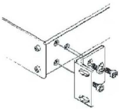
- Attach both ear brackets to the machine. To do so, remove the screws from each side of the machine (3 on each side), and replace those screws through the ear brackets.
natural_image
Technical line drawing of a mechanical bracket assembly (no text or symbols)- Place the ears of the machine against the rack rails, and insert the proper screws (not provided) through each of the four holes in the rack ears.
Note:
• In some models, the front panel may feature built-in rack ears
- Detachable rack ears can be removed for desktop use
• Always mount the machine in the rack before you attach any cables or connect the machine to the power
- If you are using a Kramer rack adapter kit (for a machine that is not 19"), see the Rack Adapters user manual for installation instructions available from:
http://www.kramerelectronics.com
6 Connecting Your SP-10D Digital Video Processor
You can use your SP-10D to convert composite video, s-Video, or component video (YUV or RGB/S) signals to composite video, s-Video, and ^1 component video (YUV, RGsB, RGBS, RGBHV). The processing can be evaluated on a “Before/after” split-screen.
To connect the SP-10D Digital Video Processor, do the following ^2 :
-
Connect the following sources to the SP-10D:
-
The composite video source (for example, a video player) to the CV INPUT BNC connector
-
The s-Video source (for example, an s-Video player) to the Y/C INPUT 4-pin connector
-
Connect the component video INPUT BNC connectors, G/Y, B/B-Y, and R/R-Y to either a YUV or an RGB video source, as follows:
• A video player source to G/Y, R/R-Y, and B/B-Y, or
- A camera (RGBS) source to G/Y, R/R-Y, B/B-Y and SYNC
-
Connect the following acceptors to the SP-10D:
-
The SPLITTER OUTPUT BNC connector to a composite video display
- The Y/C OUTPUT 4-pin connector to an s-Video display
- The CV OUTPUT BNC connector to a composite video display
-
The five BNC OUTPUTS connectors: G/Y, B/B-Y, R/R-Y, Vs/Cs, and Hs/Cs to a video acceptor (for example, a plasma display)
-
Connect the LOOP BNC connector to the next SP-10D genlocked unit (if required) and release the Term button for looping ^3 .
- Connect a genlock source to the SYNC BNC connector.
- Connect a PC or other controller, if required (see section 6.1).
- Set the DIP-switches (see section 6.2).
- Connect the power cord ^4 (not illustrated in Figure 2).

flowchart
graph TD
    A["Composite Video Player"] -->|CV| B["Server"]
    C["s-Video Player"] -->|Y/C| B
    D["Video Player (Y, R-Y, B-Y Source)"] -->|RGB| B
    E["Camera (RGBS Source)"] -->|RGBS| B
    F["Composite Video Display (showing split Image)"] -->|CV| G["Computer"]
    H["s-Video Display"] -->|Y/C| I["Computer"]
    J["Composite Video Display"] -->|CV| K["Computer"]
    L["Plasma Display"] -->|RGB HV| M["RS-232"]
    N["Genlock Source"] --> B
    O["Next Genlocked Unit"] --> B
Figure 2: Connecting the SP-10D Digital Video Processor
6.1 Connecting a PC
You can connect to the unit via a crossed RS-232 connection, using for example, a PC. A crossed cable or null-modem is required as shown in method A and B respectively. If a shielded cable is used, connect the shield to pin 5.
Method A (Figure 3)—Connect the RS-232 9-pin D-sub port on the unit via a crossed cable (pin 2 to pin 3, pin 3 to pin 2, and pin 5 to pin 5) to the RS-232 9-pin D-sub port on the PC.
Note: There is no need to connect any other pins.
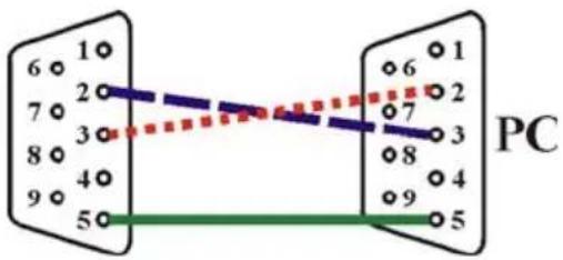
Figure 3: Crossed Cable RS-232 Connection
Hardware flow control is not required for this unit. In the rare case where a controller requires hardware flow control, short pin 1 to 7 and 8, and pin 4 to 6 on the controller side.
Method B (Figure 4)—Connect the RS-232 9-pin D-sub port on the unit via a straight (flat) cable to the null-modem adapter, and connect the null-modem adapter to the RS-232 9-pin D-sub port on the PC. The straight cable usually contains all nine wires for a full connection of the D-sub connector. Because the null-modem adapter (which already includes the flow control jumpering described in Method A above) only requires pins 2, 3 and 5 to be connected, you are free to decide whether to connect only these 3 pins or all 9 pins.

Figure 4: Straight Cable RS-232 Connection with a Null Modem Adapter
6.2 DIP-Switch Settings
The SP-10D DIP-switch settings are defined in Table 3 and Table 4:
Table 3: DIP-switch Settings
| DIP-Switch Set | as Follows: | |
| 1 | Pedestal ON for pedestal of output signal (7.5 IRE offset selection for NTSC); OFF for no pedestal | |
| 2 | HsVs/Cs ON for Composite Sync on outputs Hs/Cs and Vs/Cs; OFF for Horizontal Sync on Hs/Cs, and Vertical Sync on Vs/Cs outputs | |
| 3 | Secam VBI | ON for insert identification signals occupying 9 lines of field-blanking period (only for SECAM output standard) (bottle pulses); OFF for no insert (no bottle pulses) |
| 4,5,6 | Test Signals | The status of these DIP-switches defines the test signal: see Table 4 |
| 7 | AGC ON for enabling automatic gain control; OFF for disabling automatic gain control | |
| 8 | ADDR For selecting one of two machine addresses (defining the machine address) | |
Table 4: Test Signals
| The SP-10D DIP 4 DIP 5 DIP 6 | |||
| VITS 330 (Modulated Staircase) – full field mode ON | ON ON | ||
| No Signal^1 | OFF | ||
| Split 75% Bar Generator ON ON OFF | |||
| VITS 18 (Multiburst 5.8MHz) – full field mode ON OFF ON | |||
| Vertical 75% Bar Generator ON OFF OFF | |||
| Inverse Horizontal 75% Bar Generator OFF OFF ON | |||
| Horizontal 75% Bar Generator OFF ON OFF | |||
| VITS 17 (2T, 20T, 5 Step Staircase) – full field mode OFF ON | ON |
7 Operating the SP-10D Digital Video Processor
Operate your SP-10D Digital Video Processor via:
- The front panel buttons
- RS-232 serial commands transmitted by a touch screen system, PC, or other serial controller
To operate the SP-10D using the front panel buttons, do the following:
- Turn on the power and after it has completed its warm up sequence, press the INPUT button to select the source—CV, YC, YUV, or RGB/S—that you want to convert. The appropriate INPUT LED lights (indicating selection and conversion of that source).
- When the AUTO button illuminates, the video standard corresponding to the selected input is detected automatically. The appropriate INPUT STANDARD LED lights: PAL B, PAL N, PAL M, NTSC 3.58, NTSC 4.43 or SECAM ^2 . When the AUTO button does not illuminate—that is, the SP-10D is in manual mode—select the desired video standard by pressing the AUTO button to cycle between the various video standards.
- Press the (Component) OUTPUT button to select the component output signal format: YUV, RGsB, or RGBS.
- Press the STORE button twice to save the previous selection (power down saving: optional).
-
Press the STANDARDS button to select the output standard of the composite video signal. The appropriate OUTPUT STANDARDS LED flashes as well as the STORE button. However, the output standard is not altered.
-
Press the STORE button once.
For 5 seconds no output video signal is available, and “rL” is displayed in the 7-segment display, indicating that the SP-10D is reloading.
After the reloading, the standard of the output video signal changes as well as that of the “Before/after” split-screen.
- Press the GENLOCK button to enable the genlock function.
If the SYNC BNC connector ^1 is connected to a genlock source, and the standard of the signal on this input coincides with the standard of the output video signal, the GENLOCK button illuminates. If not, the GENLOCK button flashes.
- Adjust the color ^2 , brightness, contrast, hue, sharpness ^3 , H-shift, V-shift ^4 , (Delay, SCH if required for genlock) and/or the video gain of the picture, as follows:
- Press the appropriate button ^5
The button illuminates, and flashes, and the 7-segment display shows the current level (in digits)
The digit “0” corresponds to the normal level (“NORM”)
- Press the + button or – button once to gradually increase or decrease the current level by one unit (the 7-segment display shows the new level).
To increase or decrease the current level rapidly, press and hold down the + button or - button, continuously ^6 . To end the rapid adjustment, release the + button or - button
Note, if you want to:
- Set the normal level (“NORM”) of the current level, press and simultaneously hold down both the + button and – button. The 7-segment display shows “0”
- Undo the adjustment, press the appropriate button one more time. The appropriate button no longer flashes
- Save the result of the adjustment, press the STORE button twice
- Store the result of the adjustment in another setup #, press the STORE button once, select a setup # between 1 and 16 by pressing the + and - buttons, and then press the STORE button once again
If the adjustment is set such that the level setting is at its normal level (“NORM”), the appropriate button no longer illuminates (otherwise this button continues to illuminate in the main mode).
7.1 Storing and Recalling Setups
You can store and recall up to 16 setups (or adjustments) in non-volatile memory, using the STORE and RECALL buttons together with the + and - buttons.
To store ^1 a setup, do the following:
- Press the STORE button and then select a setup # between 1 and 16 by pressing the + and - buttons (the current settings are saved to that setup #)
- Press the STORE button once again
To recall a setup, do the following:
- Press the RECALL button and then select the appropriate # (that corresponds to the setup #) by pressing the + and - buttons (the selected setup is recalled)
- Press the RECALL button once again
7.2 Locking the Front Panel
To prevent changing the settings unintentionally or tampering with the front panel, lock your SP-10D. Unlocking releases the protection mechanism.
To lock the SP-10D:
- Press the PANEL LOCK button (for about 2 seconds) until it illuminates — freezing the front panel controls. Pressing a button has no effect ^2 , except to cause the PANEL LOCK button to flash ^3 and show the value of a ProcAmp setting if its button is pressed ^4
To unlock the SP-10D:
- Press the PANEL LOCK button (for about 2 seconds) until the front panel controls unlock and the PANEL LOCK button no longer illuminates
8 Technical Specifications
Table 5 includes the technical specifications:
Table 5: Technical Specifications ^1 of the SP-10D Digital Video Processor
| INPUTS: 1 composite video: | 1Vpp/75Ω on a BNC connector;1 YC: 1Vpp/75Ω (Y), 0.3Vpp/75Ω (C) on a 4-pin connector;1 component: Y/R-Y/B-Y (or RGB/S) 1Vpp/0.7Vpp/0.7Vpp/75Ω on BNC connectors;1 SYNC (genlock): looped 75Ω/Hi-Z on BNC connectors |
| OUTPUTS: | 1 composite video: 1Vpp/75Ω on a BNC connector;1 YC: 1Vpp/75Ω (Y), 0.3Vpp/75Ω (C) on a 4-pin connector;1 component: Y/R-Y/B-Y (or RGB/S) 1Vpp/0.7Vpp/0.7Vpp/75Ω on BNC connectors |
| VIDEO STANDARDS: PAL-B/D/G/H/I/M/N, NTSC-3.58/4.43, SECAM | |
| DIGITAL RESOLUTION: 10 bits | |
| BANDWIDTH (-3dB): 5MHz | |
| DIFF. GAIN: 1% | |
| DIFF. PHASE: 1Deg. | |
| K-FACTOR: | 0.4% |
| S/N RATIO: 60dB | |
| LUMA NON-LINEARITY: 1% | |
| CHROMA/LUMA DELAY: <15ns | |
| MEMORY: Non-volatile memory for storage of 16 setups | |
| CONTROLS: Front-panel and RS-232: contrast, brightness, video gain, color, hue, H/V sharpness, SCH phase, delay, H/V shift; R, G, B, R-Y, B-Y level; screen splitter (process to bypass); freeze; panel lock | |
| POWER SOURCE: | Universal, 100-240V AC, 50/60Hz, 27VA |
| DIMENSIONS: | 19" x 7" x 1U W, D, H, rack mountable |
| WEIGHT: | 2.6kg (5.7lbs) approx. |
| ACCESSORIES: | Power cord, null-modem adapter |
9 Communication Protocol
This protocol, which enables RS-232 communication between the SP-10D and the PC, uses 4 bytes of information, and data is at 9600 baud.
Table 6: Protocol Definitions
First byte options
| DEC HEX | ||||
| 1 | 128 | 80 | RESET | VIDEO |
| 2 | 160 | A0 | READ | PARAMETER |
| 3 | 161 | A1 | WRITE | PARAMETER |
| 4 | 162 | A2 | RECALL | |
| 5 | 163 | A3 | STORE | |
| 6 | 189 | BD | IDENTIFY | MACHINE |
| 7 33 21 Set (for the rest of commands) | ||||
| Second byte is the command type | ||||
| Third byte is the parameter value | ||||
Note:
- When working in HEX, add 80 to the values in the table.
- When working in DEC, add 128 to the values in the table.
- All values in the table are in DEC.
| Byte 2 | Command Description | Byte 3 (parameter value) |
| 0 INPUT FORMAT | 0 - CV | |
| 1 - YC | ||
| 2 - YUV | ||
| 3 - RGB/S | ||
| 4 - SDI | ||
| 1 INPUT_STANDARD | 0 - PAL B | |
| 1 - PAL N | ||
| 2 - PAL M | ||
| 3 - NT 3 | ||
| 4 - NT 4 | ||
| 5 - SEC | ||
| 6 - AUTO | ||
| (READ 19 - INPUT_STANDARD_AUTO) | ||
| 2 SPLITTER | -100 +100 | |
| 3 SHARP_H | 0 - 15 | |
| 4 SHARP_V | 0 - 15 | |
| 5 CONTRAST | -100 +100 | |
| 6 BRIGHTNESS | -100 +100 | |
| 7 VIDEO_GAIN | -100 +100 | |
| 8 H_SHIFT | -16 - +15 | |
| 9 V_SHIFT | -1 - +1 | |
| 10 | Y | -100 - +100 |
| 11 | U | 100 - +100 |
| 12 | V | 100 - +100 |
| 13 | GREEN | -100 - +100 |
| 14 | BLUE | -100 - +100 |
| 15 | RED | -100 - +100 |
| 16 | COLOR | -100 - +100 |
| 17 | HUE | -100 - +100 |
| 18 | COLOR_SPACE | 0 - OFF |
| 1 - YUV | ||
| 2 - RGB | ||
| 19 | INPUT_STANDARD_AUTO | (READ ONLY) |
| 0 - PAL B | ||
| 1 - PAL N | ||
| 2 - PAL M | ||
| 3 - NT 3 | ||
| 4 - NT 4 | ||
| 5 - SEC | ||
| Byte 2 | Command Description Byte 3 (parameter value) | |
| GLOBAL | ||
| 20 | OUTPUT FORMAT 0 - YUV | |
| 1 - RGB | ||
| 2 - RGBS | ||
| 21 | OUTPUT_STANDARD 0 - PAL B | |
| 1 - PAL N | ||
| 2 - PAL M | ||
| 3 - NT 3 | ||
| 4 - NT 4 | ||
| 5 - SEC | ||
| 22 | GENLOCK 0 - OFF | |
| 1 - ON | ||
| 23 | PANEL_LOCK 0 - OFF | |
| 1 - ON | ||
| 24 | SCH -100 - +100 | |
| 24 | DELAY -100 - +100 | |
| 26 | FREEZE 0 - OFF | |
| 1 - ON | ||
| 27 | PROGRAM 0 - 15 (read only) | |
| 28 | GENLOCK_STAT | (Read only) |
| 0 - No | GENLOCK | |
| 1 - GENLOCK | ||
Byte 4 is the machine address: can be 98 or 99 (in HEX).
First byte = I
Second byte=D
Third byte=E
MACHINE TO PC:
| MACHINE POWER-UP |
| PC <- I = 34;D = 0;E = PROGRAMM NUMBER <- MACHINE (RECALL) |
| PRESS OF "RECALL" |
| PC <- I = 34;D = 0;E = PROGRAMM NUMBER <- MACHINE (RECALL) |
| PRESS OF "STORE" |
| PC <- I = 34;D = 0;E = PROGRAMM NUMBER <- MACHINE (RECALL) |
| CHANGE "OUTPUT_STANDARD" |
| PC <- I = 34;D = 0;E = PROGRAMM NUMBER <- MACHINE (RECALL) |
| CHANGING OTHER KEYS |
| PC <- I = 33;D = PARAMETER NUMBER; E = PARAMETER <- MACHINE (PARAMETER WRITE) |
PC TO MACHINE:
| RESET VIDEO |
| POWER-UP(PSEUDO) |
| PC -> I = 0;D = 0;E = 0 -> MACHINE |
| PC <- I = 0;D = 0;E = 0 <- MACHINE |
| DEFAULT |
| PC -> I = 0;D = 1;E = 0 -> MACHINE |
| WRITE EEPROM ALL PARAMETERS - DEFAULT (ALL PROGRAMS),RELOAD (RESTART) |
| PC <- I = 34;D = 0;E = PROGRAMM NUMBER <- MACHINE (RECALL) |
| PARAMETER READ |
| PC -> I = 32;D = PARAMETER NUMBER;E = 0 -> MACHINE |
| PC <- I = 32;D = PARAMETER NUMBER;E = PARAMETER <- PARAMETER |
| PARAMETER WRITE |
| PC -> I = 33;D = PARAMETER NUMBER;E = PARAMETER -> MACHINE |
| PC <- I = 33;D = PARAMETER NUMBER;E = PARAMETER <- MACHINE |
| WRITE OUTPUT_STANDARD |
| PC -> I = 33;D = 21;E = PARAMETER -> MACHINE MACHINE RELOAD (RESTART) |
| PC <- I = 34;D = 0;E = PROGRAMM NUMBER <- MACHINE (RECALL) |
| RECALL |
| PC -> I = 34;D = 0;E = PROGRAMM NUMBER -> MACHINE |
| PC <- I = 34;D = 0;E = PROGRAMM NUMBER <- MACHINE |
| PROGRAMM NUMBER - 0 = PROGRAMM 1 |
| PROGRAMM NUMBER - 1 = PROGRAMM 2 |
| PROGRAMM NUMBER - 15 = PROGRAMM 16 |
| S | T | O | R | |
| PC -> I = 35;D = 0;E = PROGRAMM NUMBER -> MACHINE | ||||
| PC <- I = 34;D = 0;E = PROGRAMM NUMBER <- MACHINE (RECALL) | ||||
| IDENTIFY | MACHINE | |||
| MACHINE | NAME | |||
| PC -> I = 61;D = 1;E = 0 -> MACHINE | ||||
| PC <- I = 61;D = MACHINE NAME HIGH;E = MACHINE NAME LOW <- MACHINE | ||||
| SOFTWARE | VERSION | |||
| PC -> I = 61;D = 3;E = 0 -> MACHINE | ||||
| PC <- I = 61;D = SOFTWARE VERSION HIGH;E = SOFTWARE VERSION LOW <- MACHINE | ||||
E
Examples:
- Select CV input format:
H21 H80 H80 H98
Unit response:
H61 H80 H80 H98
- Reset:
H80 H80 H80 H98
- Recall set up 1:
HA2 H80 H80 H98
DEC: 162 128 128 152
- Store set up 2:
HA3 H80 H81 H98
DEC: 162 128 129 152
LIMITED WARRANTY
Kramer Electronics (hereafter Kramants this product free from defects in material and workmanship under the following terms.
HOW LONG IS THE WARRANTY
Labor and parts are warranted for seven years from the date of the first customer purchase.
WHO IS PROTECTED?
Only the first purchase customer may enforce this warranty.
WHAT IS COVERED AND WHAT IS NOT COVERED
Except as below, this warranty covers all defects in material or workmanship in this product. The following are not covered by the warranty:
- Any product which is not distributed by Kramer, or which is not purchased from an authorized Kramer dealer. If you are uncertain as to whether a dealer is authorized, please contact Kramer at one of the agents listed in the Web site www.kramerelectronics.com.
- Any product, on which the serial number has been defaced, modified or removed, or on which the WARRANTY VOID IF TeamRERE, Posticked as otherwise, interfered with.
- Damage, deterioration or malfunction resulting from:
i) Accident, misuse, abuse, neglect, fire, water, lightning or other acts of nature
ii) Product modification, or failure to follow instructions supplied with the product
iii) Repair or attempted repair by anyone not authorized by Kramer
iv) Any shipment of the product (claims must be presented to the carrier)
v) Removal or installation of the product
vi) Any other cause, which does not relate to a product defect
vii) Cartons, equipment enclosures, cables or accessories used in conjunction with the product
WHAT WE WILL PAY FOR AND WHAT WE WILL NOT PAY FOR
We will pay labor and material expenses for covered items. We will not pay for the following:
- Removal or installations charges.
- Costs of initial technical adjustments (set-up), including adjustment of user controls or programming. These costs are the responsibility of the Kramer dealer from whom the product was purchased.
- Shipping charges.
HOW YOU CAN GET WARRANTY SERVICE
- To obtain service on you product, you must take or ship it prepaid to any authorized Kramer service center.
- Whenever warranty service is required, the original dated invoice (or a copy) must be presented as proof of warranty coverage, and should be included in any shipment of the product. Please also include in any mailing a contact name, company, address, and a description of the problem(s).
- For the name of the nearest Kramer authorized service center, consult your authorized dealer.
LIMITATION OF IMPLIED WARRANTIES
All implied warranties, including warranties of merchantability and fitness for a particular purpose, are limited in duration to the length of this warranty.
EXCLUSION OF DAMAGES
The liability of Kramer for any effective products is limited to the repair or replacement of the product at our option. Kramer shall not be liable for:
- Damage to other property caused by defects in this product, damages based upon inconvenience, loss of use of the product, loss of time, commercial loss; or:
- Any other damages, whether incidental, consequential or otherwise. Some countries may not allow limitations on how long an implied warranty lasts and/or do not allow the exclusion or limitation of incidental or consequential damages, so the above limitations and exclusions may not apply to you.
This warranty gives you specific legal rights, and you may also have other rights, which vary from place to place.
NOTE: All products returned to Kramer for service must have prior approval. This may be obtained from your dealer.
This equipment has been tested to determine compliance with the requirements of:
EN-50081: "Electromagnetic compatibility (EMC); generic emission standard.
Residential, commercial and light industry"
EN-50082: "Electromagnetic compatibility (EMC) generic immunity standard. Part 1: Residential, commercial and light industry environment".
CFR-47: FCC* Rules and Regulations:
Part 15: "Radio frequency devices
Subpart B Unintentional radiators"
CAUTION!
Servicing the machines can only be done by an authorized Kramer technician. Any user who makes changes or modifications to the unit without the expressed approval of the manufacturer will void user authority to operate the equipment.
Use the supplied DC power supply to feed power to the machine.
☒ Please use recommended interconnection cables to connect the machine to other components.
* FCC and CE approved using STP cable (for twisted pair products)
For the latest information on our products and a list of Kramer distributors, visit our Web site: www.kramerelectronics.com, where updates to this user manual may be found.
We welcome your questions, comments and feedback.

Caution
Safety Warning:
Disconnect the unit from the power supply before opening/servicing.

CE


- Kramer Electronics, Ltd.
- USER MANUAL
- Contents
- Figures
- Tables
- Introduction
- Getting Started
- Quick Start
- Overview
- Control the SP-10D:
- Your SP-10D Digital Video Processor
- Your SP-10D Digital Video Processor
- Installing the SP-10D in a Rack
- Before Installing in a Rack
- CAUTION!
- How to Rack Mount
- Connecting Your SP-10D Digital Video Processor
- Connecting a PC
- DIP-Switch Settings
- Operating the SP-10D Digital Video Processor
- Storing and Recalling Setups
- Locking the Front Panel
- Technical Specifications
- Communication Protocol
- Note:
- LIMITED WARRANTY
- HOW LONG IS THE WARRANTY
- WHO IS PROTECTED?
- WHAT IS COVERED AND WHAT IS NOT COVERED
- WHAT WE WILL PAY FOR AND WHAT WE WILL NOT PAY FOR
- HOW YOU CAN GET WARRANTY SERVICE
- LIMITATION OF IMPLIED WARRANTIES
- EXCLUSION OF DAMAGES
- Safety Warning:
Brand : Kramer
Model : SP-10D
Category : Audiovisual Equipment