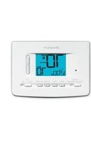
2220 - Thermostat Braeburn - Free user manual and instructions
Find the device manual for free 2220 Braeburn in PDF.


| Product Type | Programmable Thermostat |
| Brand | Braeburn |
| Model | 2220 |
| Dimensions | 4.5 x 3.5 x 1.2 inches |
| Weight | 0.5 lbs |
| Power Source | 24 VAC or 2 AA batteries (backup) |
| Display | Digital LCD with backlight |
| Temperature Range | 40°F to 90°F (4°C to 32°C) |
| Programmable Schedules | 7-day, 4 periods per day |
| System Compatibility | Gas, oil, electric, heat pump (1H/1C) |
| Number of Stages | 1 Heat / 1 Cool |
| Installation | Wall mount; requires C-wire or battery operation |
| Main Functions | Temperature control, programmable scheduling, hold, filter change reminder, low battery indicator |
| Care and Cleaning | Use a soft dry cloth; do not use liquids or chemicals |
| Safety Certifications | UL listed, CSA certified |
| Spare Parts | Optional wall plate, replacement batteries |
| General Information | Energy Star certified, 5-year limited warranty |
Frequently Asked Questions - 2220 Braeburn
User questions about 2220 Braeburn
0 question about this device. Answer the ones you know or ask your own.
Ask a new question about this device
Download the instructions for your Thermostat in PDF format for free! Find your manual 2220 - Braeburn and take your electronic device back in hand. On this page are published all the documents necessary for the use of your device. 2220 by Braeburn.
USER MANUAL 2220 Braeburn
2020 Single Stage Heat / Cool Conventional and Heat Pump
2220 Up to 2 Heat / 2 Cool Conventional Up to 2 Heat / 1 Cool Heat Pump
Model number is located on back of thermostat
1 Specifications
6 Setting Your Program Schedule
2 About Your Thermostat
7 Operating Your Thermostat
3 Installation
8 Additional Operation Features
4 System Testing
9 Thermostat Maintenance
5 Setting User Options

Warning
Turn off power to the heating or cooling equipment before installation.

Attention
For installation by experienced service technicians only.
Read all instructions before proceeding.
This thermostat requires 24 Volt AC Power or two (2) properly installed "AA" Alkaline batteries for proper operation. When connecting 24 Volt AC Power the batteries may be installed as a backup.
For use only as described in this manual. Any other use will void warranty.
1 Specifications
This thermostat is compatible with:
- Single stage heat / cool conventional and heat pump systems
- Conventional systems up to 2 heat / 2 cool (2220 only)
- Single compressor heat pump systems with an auxiliary heat stage (2220 only)
• 250 – 750 millivolt heat only systems
Electrical and control specifications:
• Electrical Rating: 24 Volt AC
- 1 amp maximum load per terminal
• AC Power: 18 – 30 Volts AC
- DC Power: 3.0 Volt DC (2 "AA" Alkaline Batteries Included)
• Control Range: 45^-90^ F ( 7^-32^ C)
• Temperature Accuracy: +/- 1° F (+/- .5° C)
Terminations
• 2020 – Rc, Rh, O, B, Y1, W1, G, C
• 2220 – Rc, Rh, O, B, Y1, Y2, E/W1, G, W2, C
2 About Your Thermostat

1 Room Temperature......Displays the current room temperature
2 Day of Week....Displays the current day of week
3 Program Event Indicator..Indicates the current program event
4 Time of Day......Displays the current time of day
5 Low Battery Indicator ..... Indicates when batteries need to be replaced
6 Fan Indicator......Indicates when the system fan is running
7 Hold Mode Indicator......Displays if in HOLD mode
8 System Status Indicator...Displays information about system status
9 Set Temperature......Displays the current set point temperature
10 Service Filter Indicator.....Displays service/maintenance reminders

11 Reset Button ...... Resets thermostat back to factory defaults
12 System Switch ..... Selects system preference
13 PROG Button......Selects programming mode
14 HOLD Button ......Enters/Exits the HOLD mode (program bypass)
15 RETURN Button......Returns to normal from program or setting modes
16 DAY/TIME Button ...Used to set the time and day of week
17 Quick Reference
Instructions ...... Stored in slot at top of thermostat
18 Arrow Buttons ..... Used to increase or decrease settings
19 Fan Switch......Selects the system fan mode
Battery Compartment .... Located in back of the thermostat
3 Installation

Warning
Disconnect power before beginning installation.
Thermostat Location
Install the thermostat approximately 5 feet (1.5m) above the floor in an area that has a good amount of air circulation and maintains an average room temperature.
Avoid installation in locations where the thermostat can be affected by drafts, dead air spots, hot or cold air ducts, sunlight, appliances, concealed pipes, chimneys and outside walls.

natural_image
Simple line drawing of a room interior with a door, window, and wall-mounted equipment (no text or symbols)Install your new Braeburn thermostat in 5 basic steps:
1 Install the Sub-Base
2 Provide Power
3 Connect Your Wires
4 Set Installer Switches
5 Attach Thermostat to Sub-Base
1 Install the Sub-Base:
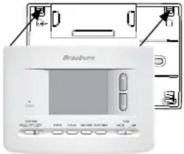
- Remove the sub-base from the body of the thermostat.
- Mount the sub-base as shown below:

NOTE: After sub-base installation, you may insert the quick reference card into the slot on the top of the base.
2
Provide Power

- For 24 Volt AC power, you must connect the common side of the transformer to the C terminal on the thermostat sub-base.
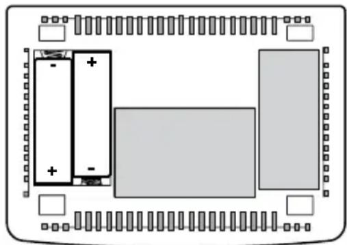
- For primary or back-up power, insert the 2 supplied "AA" type alkaline batteries into the battery compartment located in the rear housing of the thermostat. Make sure to position the Positive (+) and Negative (-) sides of the batteries correctly with the +/- symbols in the battery compartment.
3
Connect Your Wires
Wiring Terminations
| Terminal | Function | Description |
| Rc | Input | 24 Volt AC Cooling Transformer(Dual Transformer Systems Only) |
| Rh | Input | Power Connection (24 Volt AC HeatingTransformer or Millivolt Power Source) |
| O | Output | Reversing Valve (Cool Active) |
| B | Output | Reversing Valve (Heat Active) |
| Y1 | Output | Compressor Relay |
| G | Output | Fan Control |
| W1 | Output | Conventional Heat Relay |
| C | Input | 24 Volt AC Transformer Common |
Additional Terminations (2220 only)
| Terminal | Function | Description |
| W1/E | Output | (W1) 1st Stage Conventional Heat(E) Emergency Heat Relay |
| Y2 | Output | 2nd Stage Conventional Cooling Compressor |
| W2 | Output | 2nd Stage Heat / Auxiliary Heat |
Conventional Systems
Typical Wiring Configurations
NOTE: The "Installer Switch" option will be configured in the next step.
Heat Only or Millivolt
Set Installer Switch to CONV
| Rh | Power Connection | |
| W | Heat Relay (appears as W1/E on 2220) | |
| G | Fan Relay [note 4] | |
| C | 24 Volt AC Transformer Common [note 1] | |
1 HEAT / 1 COOL Single or Dual Transformer
Set Installer Switch to CONV
| Rh | 24 Volt AC Power (heating transformer) [note 2] |
| Rc | 24 Volt AC Power (cooling transformer) [note 2] |
| W1 | Heat Relay (appears as W1/E on 2220) |
| Y1 | Compressor Relay |
| G | Fan Relay |
| C | 24 Volt AC Transformer Common [note 1, 3] |
2 HEAT / 2 COOL Single or Dual Transformer (2220 Only)
Set System Type to CONV
| Rh | 24 Volt AC Power (heating transformer) [note 2] |
| 24 Volt AC Power (cooling transformer) [note 2] | |
| W1 | Heat Relay Stage 1 |
| W2 | Heat Relay Stage 2 |
| Y1 | Compressor Relay Stage 1 |
| Y2 | Compressor Relay Stage 2 [note 4] |
| G | Fan Relay |
| C | 24 Volt AC Transformer Common [note 1, 3] |
NOTES - Conventional Systems
[1] If batteries are installed the 24 Volt AC common connection is optional
[2] Remove factory installed jumper for dual transformer systems
[3] In dual transformer systems, transformer common must come from cooling transformer
[4] If needed for system
Provide disconnect and overload protection as required.
Heat Pump Systems
Typical Wiring Configurations
NOTE: The "Installer Switch" option will be configured in the next step.
1 HEAT / 1 COOL - No Auxiliary Heat
Set Installer Switch to HP
| Rh | 24 Volt AC Power |
| Rc | Connected to Rh with supplied Jumper Wire |
| O or B | Changeover Valve [note 2] |
| Y1 | Compressor Relay |
| G | Fan Relay |
| C | 24 Volt AC Transformer Common [note 1] |
2 HEAT / 1 COOL - Including Auxiliary Heat (2220 only)
Set Installer Switch to HP
| Rh | 24 Volt AC Power |
| Rc | Connected to Rh with supplied Jumper Wire |
| O or B | Changeover Valve [note 2] |
| Y1 | Compressor Relay (1st stage heating/cooling) |
| W2 | Auxiliary Heat Relay (2nd stage heating) [note 3] |
| E | Emergency Heat Relay [note 3] |
| G | Fan Relay |
| C | 24 Volt AC Transformer Common [note1] |
NOTES - Heat Pump Systems
[1] If batteries are installed the 24 Volt AC common connection is optional.
[2] Select O for cool active or B for heat active.
[3] Install a field supplied jumper between the W2 and E terminals if there is no separate emergency heat relay installed.
Provide disconnect and overload protection as required.
4 Set Installer Switches
The Installer switches are located on the back of the thermostat and must be properly configured for this thermostat to operate properly.
| Factory Switch | Setting Default Options | Comments | |
| CONV / HP | CONV | CONV | Select for conventional systems |
| HP | Select for heat pump systems | ||
| F / C F | F | Select for fahrenheit temperature scale | |
| C | Select for celsius temperature scale | ||
| HE / HG | HG | HG | Select for gas heat |
| HE | Select for electric heat | ||
NOTE: Installer switches are located on the back of the thermostat. The reset button must be pressed after making any changes to these switches.
5 Attach Thermostat to Sub-Base
- Line up the thermostat body with the sub-base.
- Carefully push the thermostat body against the sub-base until it snaps into place.
- Insert quick reference card into slot on top of thermostat.
4 System Testing

Warning Read Before Testing
- Do not short (or jumper) across terminals on the gas valve or at the heating or cooling system control board to test the thermostat installation. This could damage the thermostat and void the warranty.
- Do not select the COOL mode of operation if the outside temperature is below 50^ F ( 10^ C). This could possibly damage the controlled cooling system and may cause personal injury.
- This thermostat includes an automatic compressor protection feature to avoid potential damage to the compressor from short cycling. When testing the system, make sure to take this delay into account.
NOTE: The compressor delay can be bypassed by pressing the reset button on the front of the thermostat. All user settings will be returned to factory default.
1 Move the SYSTEM switch to HEAT mode.
2 Press to raise the set temperature a minimum of 3 degrees above the current room temperature. The system should start within a few seconds. With a gas heating system, the fan may not start right away.
3 Move the SYSTEM switch to the OFF mode. Allow the heating system to fully shut down.
4 Move the SYSTEM switch to the COOL mode.
5 Press to lower the set temperature a minimum of 3 degrees below the current room temperature. The system should start within a few seconds (unless compressor short cycle protection is active – See note above).
6 Move the SYSTEM switch to the OFF mode. Allow the cooling system to fully shut down.
7 Move the FAN switch to the ON mode. The system fan should start within a few seconds.
8 Move the FAN switch to the AUTO mode. Allow the system fan to turn off.
5 Setting User Options
Advanced User Options
User options allow you to customize some of your thermostat's features. Most users will not need to make any changes to the settings in this section.
To enter the User Options menu, hold down the RETURN button for approximately 3 seconds until the screen changes and displays the first User Option.
Press the or button to change the setting for the displayed User Option. After you have made your desired setting, press RETURN to advance to the next User Option.
The thermostat will return to normal mode after your last user option is made or after no keys have been pressed for 15 seconds.
Table of User Options
| User Factory No. | No. | Setting | Comments | |
| 1 | 1st stage differential | 0.5 0.5, 1.0 or 2.0 differential of .5°, 1° or 2°F (.2°, .5° or 1°C) | Select a 1st stage temperature differential of .5°, 1° or 2°F (.2°, .5° or 1°C) | |
| 2 | 2nd stage differential (220 Only) | 2.0 | 1.0, 2.0, 3.0, 4.0, 5.0 or 6.0 | Select a 2nd temperature differential of 1°, 2°, 3°, 4°, 5° or 6°F (.5°, 1°, 1.5°, 2°, 2.5° or 3°C) |
| 3 | Extended Hold Period | LNG | LNG | Selects long (permanent) hold mode |
| 24HRS | Selects 24 hr. (temporary) hold mode | |||
| 4 | Filter Service Monitor | OFF | OFF | Disables filter service monitor feature |
| 30, 60, 90, 120, 180, 365 | Selects a number of days before the thermostat will flash a Service Filter reminder in the display. | |||
| 5 | Adaptive Recovery Mode(ARMTM) | OF REC | OF REC | Disables adaptive (early) recovery mode |
| ON REC | Enables adaptive (early) recovery mode | |||
Detailed Explanation of User Options:
Temperature Differential
(User Option 1 and 2)
The differential setting is the temperature control range that your thermostat will provide. The smaller the setting, the tighter your range of temperature control and comfort will be. The 2nd stage differential is only for systems with a second stage of heating (auxiliary heat).
Extended Hold Period
(User Option 3)
The Extended Hold Period lets you select the period your thermostat will hold the temperature when the HOLD mode is activated (See “Temperature Adjustment”). When LNG is selected the thermostat will hold your temperature indefinitely. When 24HR is selected, the thermostat will hold your temperature for 24 hours and then return to the current program at that time.
Service Filter Monitor
(User Option 4)
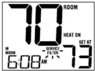
The Service Filter Monitor is a user selectable service monitor that will display a reminder for a required air filter replacement by flashing the SERVICE FILTER segment in the display. When the selected interval has been reached, and required cleaning or replacement has been performed, touch the RETURN button to reset the timer and reset the service monitor. Select OFF or a set number of days before the reminder will appear.
Adaptive Recovery Mode (early recovery)
(User Option 5)
During Adaptive Recovery Mode (ARM ^™ ), room temperature is recovered gradually by turning on the heating or cooling before the end of the set back period. The set point temperature is changed to that of the upcoming program temperature.
6 Setting Your Program Schedule
Setting the Time and Day
-
In normal operating mode, press the DAY/TIME button. The display will switch to the day/time setting mode and the hour will be flashing.
-
Press of to adjust the hour. Press DAY/TIME.
-
PresA oV to adjust the minute. Press DAY/TIME.
-
Press ∧ or ∨ to adjust the day of the week. Press RETURN to exit.

Tips Before Setting Your Program Schedule
- Make sure your current time and day of the week are set correctly.
- When programming, make sure the AM and PM indicators are correct.
This thermostat comes pre-programmed with a default energy saving program. The following table outlines the pre-programmed times and temperatures for heating and cooling in each of your 4 daily weekday and weekend events. If you wish to use these settings then no further programming is necessary:
| 5-2 Day Programming– Weekday/WeekendFactory Settings | ||
| 4 Event | Weekday | Weekend |
| MORN | Time: 6:00 amHeat: 70°F (21°C)Cool: 75°F (24°C) | Time: 6:00 amHeat: 70°F (21°C)Cool: 75°F (24°C) |
| DAY | Time: 8:00 amHeat: 62°F (17°C)Cool: 83°F (28°C) | Time: 8:00 amHeat: 70°F (21°C)Cool: 75°F (24°C) |
| EVE | Time: 6:00 pmHeat: 70°F (21°C)Cool: 75°F (24°C) | Time: 6:00 pmHeat: 70°F (21°C)Cool: 75°F (24°C) |
| NIGHT | Time: 10:00 pmHeat: 62°F (17°C)Cool: 78°F (26°C) | Time: 10:00 pmHeat: 62°F (17°C)Cool: 78°F (26°C) |
Programming a 5-2 Day Residential Schedule
The 5-2 day residential programming mode allows you to program Monday - Friday with one 4 event schedule and then allows you to change Saturday and Sunday with a different 4 event schedule.
-
Touch the PROG button. The display will switch to programming mode. The days M, TU, W, TH, and F will be displayed and the hour will be flashing.
-
Move the SYSTEM switch to either the HEA or COOL position.
-
Press the oV to adjust the hour for the MORN (morning) event. Press PROG.
-
Press on to adjust the minute for the MORN event. Press PROG.
-
Press oV to adjust the temperature for the MORN event. Press PROG.
-
Repeat steps 3-5 for the DAY, EVE and NIGHT events.
-
Repeat steps 3-6 for the weekend (S, SU) program.
-
If needed, repeat steps 2-7 to program the opposite mode (HEAT or COOL).
-
Press RETURN to exit.

7 Operating Your Thermostat
Setting the System Control Mode
The System Control has several modes of operation that can be selected by moving the SYSTEM switch to the appropriate position.
COOL Only your cooling system will operate
OFF Heating and cooling systems are off
HEAT Only your heating system will operate

Additional Switch Position (Model 2220 Only):
EMER Operates a backup heat source (Emergency Heat) for heat pump
systems only
NOTE: If your model 2220 was configured for a conventional system (CONV) then you will not have the EMER (emergency heat) option and "NO EMER SET" will flash in the display if EMER is selected with the system switch.

Setting the Fan Control Mode
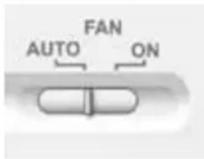
The Fan Control has 2 modes of operation – AUTO and ON. The mode can be selected by moving the FAN switch to the appropriate position.
AUTO The system fan will run only when your heating or cooling system is running
ON The system fan stays on
Temperature Adjustment
Temporary Adjustment – Press the or V button to adjust the current set point temperature.
Extended Adjustment – Press the HOLD button so that HOLD appears in the display screen. Press ∧ or ∨ to adjust the current set temperature (See “Extended Hold Period”, page 8).
Status Indicators
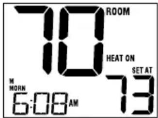
Status indicators appear in the display to let you know if your system is heating, cooling or off.
HEAT ON Indicates that your heating system is running.
COOL ON Indicates that your cooling system is running.
SERVICE Indicates that a user selectable service reminder was selected (see "Service Filter Monitor, page 8).
Additional status indicators (Model 2220 Only):
AUX Indicates that the auxiliary stage of heating is running (multi-stage systems only).
EMER Indicates that the emergency heating system is running (heat pump systems only).
Program Event Indicators
Program Event Indicators appear in the display to let you know what part of your current program is active. The 4 different program event indicators are MORN, DAY, EVE and NIGHT.
When the program event indicator is flashing, your program has been temporarily bypassed and will resume at the next scheduled event.
Note: You will not see a program event indicator while in HOLD Mode.
Resetting the Thermostat
This thermostat provides you with a reset button that will erase all of your user settings and 5-2 day programming.
To reset the thermostat, use a small object such as a tooth pick or paper-clip and gently press the button located inside the small hole on the front of the thermostat housing labeled "reset".
8 Additional Operation Features
Compressor Protection
This thermostat includes an automatic compressor protection delay to avoid potential damage to your system from short cycling. This feature activates a short delay after turning off the system compressor.
9 Thermostat Maintenance
Changing the Batteries
Depending on your particular installation, this thermostat may be equipped with two (2) "AA" type alkaline batteries.
If batteries are installed and they become low, a low battery indicator will appear in the display.
You should change your batteries immediately when you see the low battery signal by following these instructions.

- Remove thermostat body by gently pulling it from base.
- Remove old batteries and replace with new batteries.
- Make sure to correctly position the (+) and (-) symbols.
- Gently push thermostat body back onto base.
natural_image
Diagram of a rectangular electronic component with battery and resistor symbols, no text or labels presentNOTE: We recommend replacing the thermostat batteries annually or if the thermostat will be unattended for an extended period of time.
Thermostat Cleaning
Never spray any liquid directly on the thermostat. Using a soft damp cloth wipe the outer body of the thermostat. Never use any abrasive cleansers to clean your thermostat.
Store this manual for future reference
Limited Warranty
When installed by a professional contractor, this product is backed by a 5 year limited warranty. Limitations apply. For limitations, terms and conditions, you may obtain a full copy of this warranty:
- Visit us online: www.braeburnonline.com/warranty
· Phone us: 866.268.5599
· Write us: Braeburn Systems LLC 2215 Cornell Avenue Montgomery, IL 60538

Braeburn Systems LLC 2215 Cornell Avenue • Montgomery, IL 60538 Technical Assistance: www.braeburnonline.com Call us toll-free: 866-268-5599 (U.S.) 630-844-1968 (Outside the U.S.)


- Single Stage Heat / Cool Conventional and Heat Pump
- Up to 2 Heat / 2 Cool Conventional Up to 2 Heat / 1 Cool Heat Pump
- Warning
- Attention
- Read all instructions before proceeding.
- Specifications
- This thermostat is compatible with:
- Electrical and control specifications:
- Terminations
- About Your Thermostat
- Installation
- Thermostat Location
- Install your new Braeburn thermostat in 5 basic steps:
- Install the Sub-Base:
- 2
- Provide Power
- 3
- Connect Your Wires
- Conventional Systems
- Typical Wiring Configurations
- Heat Only or Millivolt
- HEAT / 1 COOL Single or Dual Transformer
- HEAT / 2 COOL Single or Dual Transformer (2220 Only)
- NOTES - Conventional Systems
- Heat Pump Systems
- HEAT / 1 COOL - No Auxiliary Heat
- HEAT / 1 COOL - Including Auxiliary Heat (2220 only)
- NOTES - Heat Pump Systems
- Set Installer Switches
- Attach Thermostat to Sub-Base
- System Testing
- Warning Read Before Testing
- Setting User Options
- Advanced User Options
- To enter the User Options menu, hold down the RETURN button for approximately 3 seconds until the screen changes and displays the first User Option.
- Detailed Explanation of User Options:
- Temperature Differential
- (User Option 1 and 2)
- Extended Hold Period
- (User Option 3)
- Service Filter Monitor
- (User Option 4)
- Adaptive Recovery Mode (early recovery)
- (User Option 5)
- Setting Your Program Schedule
- Setting the Time and Day
- Tips Before Setting Your Program Schedule
- Programming a 5-2 Day Residential Schedule
- Operating Your Thermostat
- Setting the System Control Mode
- Additional Switch Position (Model 2220 Only):
- Setting the Fan Control Mode
- Temperature Adjustment
- Status Indicators
- Additional status indicators (Model 2220 Only):
- Program Event Indicators
- Resetting the Thermostat
- Additional Operation Features
- Compressor Protection
- Thermostat Maintenance
- Changing the Batteries
- Thermostat Cleaning
- Store this manual for future reference
- Limited Warranty
Brand : Braeburn
Model : 2220
Category : Thermostat