MOS-1130Y-0201E - Uncategorized Advantech - Free user manual and instructions
Find the device manual for free MOS-1130Y-0201E Advantech in PDF.

User questions about MOS-1130Y-0201E Advantech
0 question about this device. Answer the ones you know or ask your own.
Ask a new question about this device
Download the instructions for your Uncategorized in PDF format for free! Find your manual MOS-1130Y-0201E - Advantech and take your electronic device back in hand. On this page are published all the documents necessary for the use of your device. MOS-1130Y-0201E by Advantech.
USER MANUAL MOS-1130Y-0201E Advantech
MOS-1130Y-0201E is a 2-Ports Isolated CANBus mini- PCIe, DB9.
This manual covers the pin assignment for the CAN connector, and the wiring of the two transmission wires.
1. Packing List
MOS-1130
miniPCIe Card x 1
DB37 I/O Plate x 2 with iDoor bracket x 1
FPC cable x 2
Startup Manual x 1
Note: If any of these items are missing or damaged, please contact your distributor or sales representative immediately.
2. Initial Inspection
You should find the following items inside the shipping package:
■ Mini-PCIe communication interface card
Industrial Communication Driver, Utility and mini-PCIe communication card user's manual in DVD-ROM
MOS-1130 was carefully inspected mechanically and electrically before it was shipped. It should be free of marks and scratches and in perfect working order when received.
As you unpack the MOS Module, check for signs of shipping damage (damaged box, scratches, dents, etc.). If it is damaged or it fails to meet specifications, notify our service department or your local sales representative immediately. Also notify the carrier. Retain the shipping carton and packing material for inspection by the carrier.
After inspection we will make arrangements to repair or replace the unit. When you handle the MOS Module, remove it from its protective packaging by grasping the rear metal panel. Keep the anti-vibration packing. Whenever you remove the card from the PC, store it in this package for protection.
Warning!

Discharge your body's static electric charge by touching the back of the grounded chassis of the system unit (metal) before handling the board. You should avoid contact with materials that hold a static charge such as plastic, vinyl and Styrofoam. Handle the board only by its edges to avoid static damage to its integrated circuits. Avoid touching the exposed circuit connectors. We also recommend that you use a grounded wrist strap and place the card on a static dissipative mat whenever you work with it.
3. Driver and Advantech Device Manager
Please follow the steps below to install Advantech CAN WDM Driver.
For driver download, please visit Advantech website:
http://support.advantech.com/Support/SearchResult.aspx?keyword=MOS-1130Y-0201E&searchtabs=BIOS,Certificate,Data sheet,Driver,Firmware,Manual,Online%20Training,Software%20Utility,Utility,FAQ,Installation,Software%20API,Software %20API%20Manual,3D%20Model&select_tab=Driver
- Select "Next" to continue the installation.
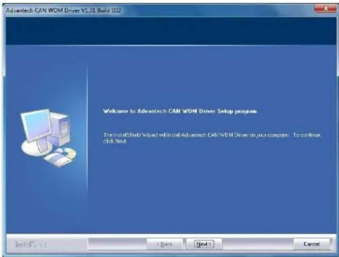
text_image
Advantech CAN WDM Driver V1.31 Build 0.02 Welcome to Advantech CAN WDM Driver Setup progress The InstallShield Wizard will install Advantech CAN WDM Drive on your computer. To continue. click Next InstallShield < Back Next > Cancel- After a while, the installation will be complete.
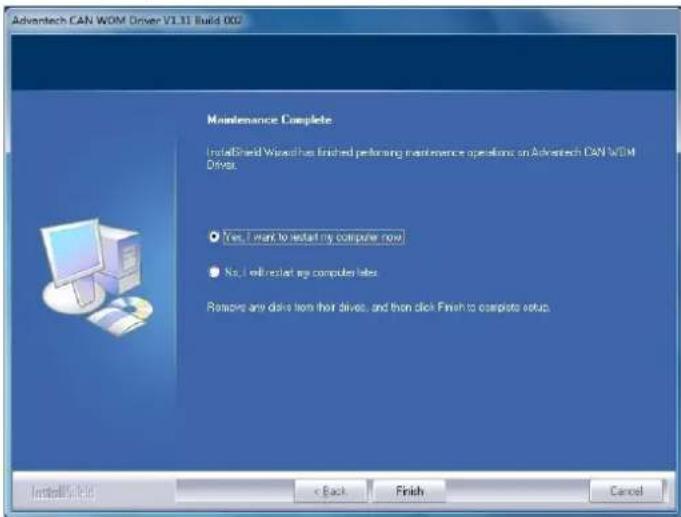
text_image
Advantech CAN WDM Driver V1.31 Build 002 Maintenance Complete InstallBrand Wizard has finished performing maintenance operations on Advantech CAN WDM Driver. Yes, I want to install my computer now No, I will restart my computer later Remove any drive from their drives, and then click Finish to complete setup. Install Style < Back Finish Cancel- After the physical hardware has been installed, the card will be automatically detected.
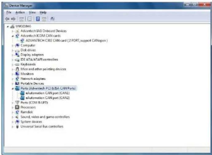
text_image
Device Manager File Action View Help UK021846 Advantech IAG Onboard Devices Advantech ICOM CAN cards ADVANTECH C302 CAN card (2 PORT, support CANopen ) Computer Disk drives Display adapters IDE ATA/ATAPI controllers Keyboards Mice and other pointing devices Monitors Network adapters Portable Devices Ports (Advantech PCI &LBA CAN Ports) eAutomation CAN port (CANL) eAutomation CAN port (CANZ) Ports (COM & LPT) Processors Ramdisk Sound, video and game controllers System devices Universal Serial Bus controllers4. Jumper and Switch Settings
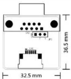
text_image
36.5 mm 32.5 mmFigure 1 CAN-bus transceiver board silk screen
4.1 How to Set Jumpers
You configure your card to match the needs of your application by setting jumpers. A jumper is the simplest kind of electric switch. It consists of two metal pins and a small metal clip (often protected by a plastic cover) that slides over the pins to connect them. To "close" a jumper you connect the pins with the clip. To "open" a jumper you remove the clip.
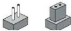
Figure 2 How to set the jumpers
4.2 Terminator Resistor Setup (JP1)
You can set the terminator resistor if necessary to match impedance. Each port has a separate resistor located on its own transceiver board.
| Table 1: MOS-1130Y-0201E Terminator Resistor Jumper Setting | ||
| Status | Value of Terminator Resistor (Ohm) | |
| Pin 2-3 | Open mode | None |
| Pin 1-2 | Close mode | 120 Ohms |
Table 1: MOS-1130 Terminator Resistor Jumper Setting
Note!
is suggested to set the terminator resistor to 120 Ohm to maintain a satisfactory baud rate performance.

MOS-1130 User Manual 3
5. Pin Assignments
Figure 3 shows the pin assignment for the card's male DB-9 connectors and corresponding pin assignments of female DB-9 connectors of the cable.
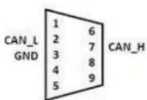
Female DB9 Connector
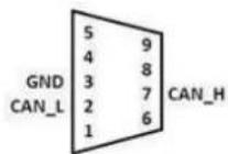
Male DB9 Connector
Figure 3 MOS-1130Y-0201E DB-9 connector pin assignments
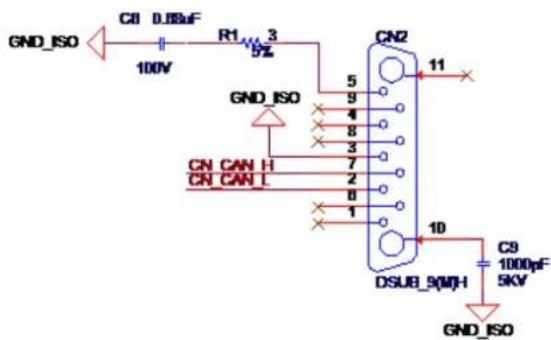
text_image
GND_ISO C8 D88uF 100V R1 3 5% 5 9 4 8 3 7 2 8 1 CN CAN H CN CAN L CN2 11 DSUB_9(MH) 10 C9 1000pF 5KV GND_ISO GND_ISOFigure 4 MOS-1130Y-0201E DB-9 connector schematics
The CAN standard supports half–duplex communication. This means that just two wires are used to transmit and receive data.
| Table 2: MOS-1130Y-0201E Terminator Resistor Jumper Setting | ||
| Pin | Signal | Description |
| 2 | CAN_L | LOW-level CAN voltage input/output |
| 3 | GND | Ground |
| 7 | CAN_H | HIGH-level CAN voltage input/output |
6. Wiring
CAN-bus main board has two FPC connectors for wiring to two CAN-bus transceiver boards through FPC cables. Please ensure to follow Figure 5 and Figure 6 for appropriate wiring in between.
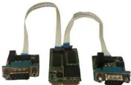
natural_image
Three electronic circuit boards with white cable connectors, no visible text or symbolsFigure 5 FPC cable wiring
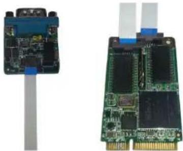
natural_image
Two electronic circuit boards with visible components and connectors, one showing a blue cable and the other a green circuit board (no text or symbols)Figure 6 Wiring on module side