
DGC-8 - Vérin pneumatique linéaire Festo - Free user manual and instructions
Find the device manual for free DGC-8 Festo in PDF.


| Product Type | Guided Cylinder (Linear Actuator) |
| Stroke Length | 8 mm |
| Piston Diameter | 8 mm |
| Maximum Operating Pressure | 8 bar (116 psi) |
| Operating Temperature Range | -20 to 80 °C |
| Weight | Approx. 0.2 kg |
| Power Supply | Pneumatic (compressed air) |
| Main Functions | Linear motion with guidance, precise positioning |
| Maintenance | Regular cleaning of guide rails, lubrication as needed |
| Safety Precautions | Ensure correct mounting, use pressure regulator, avoid overloading |
| Spare Parts Available | Seals, pistons, guide rails |
| Reparability | Repairable by qualified technician; spare parts available |
| General Information | Part of Festo's modular pneumatic system |
Frequently Asked Questions - DGC-8 Festo
User questions about DGC-8 Festo
0 question about this device. Answer the ones you know or ask your own.
Ask a new question about this device
Download the instructions for your Vérin pneumatique linéaire in PDF format for free! Find your manual DGC-8 - Festo and take your electronic device back in hand. On this page are published all the documents necessary for the use of your device. DGC-8 by Festo.
USER MANUAL DGC-8 Festo
natural_image
Technical line drawing of a linear motion guide rail with mounting brackets and central pivot block (no text or symbols)FESTO
Festo SE & Co. KG
Ruiter Straße 82
73734 Esslingen
Germany
+49 711 347-0
www.festo.com
Operating instructions
Original instructions
8075213
2017-07h
[8075215]
Linear drive DGC-8 ... 63-... English

For all available product documentation → www.festo.com/pk

Note
Fitting and commissioning is to be carried out only by qualified personnel in accordance with the operating instructions.
1 Operating elements and connections
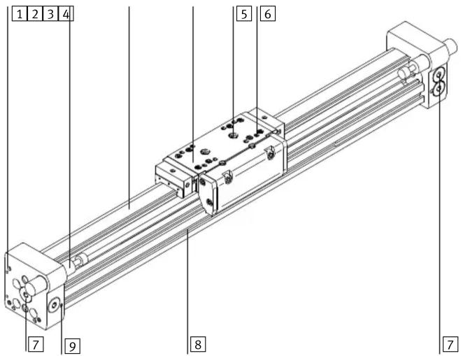
1 Thread for mounting the cylinder foot ^1) or for direct mounting
②Shock absorber or elastomer shock absorber (exchangeable → chapter “Commissioning”)
3 Guide rail
4Slide
5 Centring hole for effective load
6 Fastening thread for work load
7 Compressed air connections
8 Groove for proximity sensor 1)
9 Adjusting screw for end position cushioning
1) Accessories
Fig. 1
2 Function and application
When the compressed air is ports are pressurized alternately, the piston moves backwards and forwards in the tubing. By means of a rigid connection, the outer slide also moves. The slot in the cylinder barrel required for this is covered by a band system.
The DGC is intended for the space-saving transport of masses.
Both the slide mode and the yoke operating modes are permitted (observe loading limits).
Unpressurised movement of the slide is permitted only for fault elimination and at low speed. If the speed is too high, the resulting partial vacuum can pull the sealing band into the piston chamber. This leads to:
– severe leakage and
– impermissible accelerations (e.g. with a vertical mounting position).
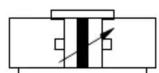
Fig. 2 Circuit symbol
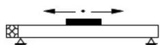
Fig. 3 Slide operation

Fig. 4 Yoke operation
3 Transport and storage

Note
- Avoid touching the guide rail with your hands during transport und storage. Otherwise the layer of grease will be damaged.
- Consider the weight of the DGC.
Depending on the design, the DGC weighs over 150 kg.
For transport, the transport belts must be spaced according to the permissible support distances (support distances Fig. 6).
4 Requirements for product use

Note
Malfunctions will occur if the device is not used correctly.
- Be sure to always comply with the specifications in this chapter.
- Note the warnings and instructions on the product and in the relevant operating instructions.
- Compare the maximum values specified in these operating instructions with your actual application (e.g. forces, torques, temperatures, masses).
Only observance of the load limits allows operation of the product in compliance with the relevant safety regulations. - Take into consideration the ambient conditions at the location of use.
Corrosive elements in the environment (e.g. ozone) will reduce the service life of the product. - Please comply with national and local safety laws and regulations.
- Use the product in its original state without any unauthorised modifications.
- Remove packaging, such as foils and cardboard.
Exception:
- The plastic cover on the aluminium guide rail (with DGC-...-G/GF).
The packing is intended for recycling (except for: oiled paper = general waste).
- Make sure that the compressed air is properly prepared 11 Technical Data
- Take the tolerance of the tightening torques into account. Unless otherwise specified, the tolerance is ± 20% .
5 Installation
5.1 Fitting mechanical components
- Avoid pushing in or sucking in the sealing band.
Damage to the sealing band reduces its reliability in operation. Jerky movement of the unpressurised slide can cause a partial vacuum that sucks the sealing band into the piston chamber. - Leave all screws and threaded bolts in their original states, unless you are requested to modify them in these instructions.
- Do not allow the band system to become damaged or excessively dirty. Damage to the DGC will reduce its reliability and service life.
- Make sure that the device is fitted free of mechanical stress and distortion.
- Use the foot mounting adapter HPC to mount the DGC on the end caps.
- Turn the mounting screws until they are equally tight.
Tightening torques [Nm]
| HPC-8 | HPC-12/18 | HPC-25 | HPC-32/40 | HPC-50 | HPC-63 |
| 0.8 | 1.6 | 2 | 4.5 | 15 | 23 |
Fig. 5
Drives with long stroke lengths:
- Use the support spacings (l) for the profile attachments MUC Fig. 6.

line
| l [mm] | Ø 8 | Ø 12 | Ø 18 | Ø 25 | Ø 32 | Ø 40 | Ø 50 | Ø 63 | |--------|--------|--------|--------|--------|--------|--------|--------|--------| | 500 | ~10000 | ~10000 | ~10000 | ~10000 | ~10000 | ~10000 | ~10000 | ~10000 | | 1000 | ~1000 | ~1000 | ~1000 | ~1000 | ~1000 | ~1000 | ~1000 | ~1000 | | 1500 | ~10 | ~10 | ~10 | ~10 | ~10 | ~10 | ~10 | ~10 | | 2000 | ~1 | ~1 | ~1 | ~1 | ~1 | ~1 | ~1 | ~1 | | 2500 | ~1 | ~1 | ~1 | ~1 | ~1 | ~1 | ~1 | ~1 | | 3000 | ~1 | ~1 | ~1 | ~1 | ~1 | ~1 | ~1 | ~1 | | 3500 | ~1 | ~1 | ~1 | ~1 | ~1 | ~1 | ~1 | ~1 | | 4000 | ~1 | ~1 | ~1 | ~1 | ~1 | ~1 | ~1 | ~1 |
line
| l [mm] | Ø = 8 | Ø = 12 | Ø = 18 | Ø = 25 | Ø = 32 | Ø = 40 | Ø = 50 | Ø = 63 | | ------ | ----- | ------ | ------ | ------ | ------ | ------ | ------ | ------ | | 1000 | ~10000 | ~10000 | ~10000 | ~10000 | ~10000 | ~10000 | ~10000 | ~10000 | | 2000 | ~1000 | ~1000 | ~1000 | ~1000 | ~1000 | ~1000 | ~1000 | ~1000 | | 3000 | ~10 | ~10 | ~10 | ~10 | ~10 | ~10 | ~10 | ~10 | | 4000 | ~1 | ~1 | ~1 | ~1 | ~1 | ~1 | ~1 | ~1 | | 5000 | ~1 | ~1 | ~1 | ~1 | ~1 | ~1 | ~1 | ~1 |Fig. 6 This shows the support spacings required for the various fittings
Fitting profile fastenings type MUC:
- Place the profile fastenings equally over the entire length of the drive, and not just over the stroke length.
- Fasten the profile fastenings on the DGC → Fig. 7.
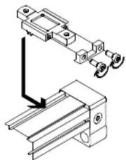
natural_image
Mechanical assembly diagram showing a bracket with rotating components and a base plate (no text or symbols)Fig. 7
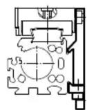

- Turn the clamping screws until they are equally tight.
Tightening torques [Nm]
| MUC-8/12 MUC | C-18 MUC-25/32 | MUC-40 MUC | 50/63 | |
| 1.2 4.1 8.3 14 20 |
Fig. 8
- Make sure that the profile attachment does not collide with the slide or effective load (especially with lateral mounting). To do this, push the slide with the effective load over the complete travel distance.
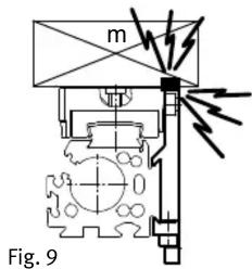
With hard and stiff effective loads:

Note
If the slide becomes bent because of a buckled effective load, the service life of the guide will be reduced.
- Make sure that the mounting surface of the effective load has the following flatness (t): - G/GF: t ≤ 0.03 mm - KF/FA: t ≤ 0.01 mm
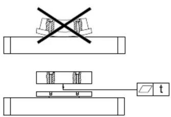
Fig. 10
- Note the tightening torques when fastening the work load on the slide:
Tightening torques [Nm]
| DGC- 8/12 18 25/32 40 50/63 | ||||||
| M4 | G | 2 | - | - | - | - |
| KF | 2.5 | |||||
| M5 | - | 3.5 3.5 3.5 - | ||||
| M6 | - | 6.5 6.5 6.5 | ||||
| M8 | - | - | 10 | |||
Fig. 11
Effective loads with own guide:
- Adjust the guides of the work load and of the DGC so that they are exactly parallel.
This is the only way to avoid overloading the slide 11 Technical Data: Perm. forces.
5.2 Fitting pneumatic components
Installation in a vertical or diagonal position:

Warning
If there is a power failure, the work mass will slide down. Danger of crushing!
- Check whether non-return valves HGL are necessary.
In this way, you can prevent the work mass from sliding down suddenly. - Check whether safety measures are necessary to prevent the mass from sinking down slowly as a result of leakage (e.g. toothed latches or moveable bolts).
- Select the supply ports.
In addition to the supply ports provided at the factory (W), there are also the alternative ports (A). These are fitted with plug screws.
W = Supply ports ex works
A = Alternative ports

5
With sizes 18 ... 63 the compressed air can be connected on one side (right).
L = end position left
R = end position right
l = movement to the left
r = movement to the right

Fig. 13
Setting the slide speed:
- Rotate the one-way flow control valves GRLA into the supply ports.
5.3 Installing the electric components
Position scanning with proximity sensors SME/SMT:
- Use grooves (S) from Fig. 16 to mount the proximity sensors.
- Observe the minimum distances between ferritic masses and the proximity sensors.
In this way you will avoid incorrect switching as a result of external influences.
Minimum clearances [mm]
| POS | 8 | 12 | 18 | 25 | 32 ... 63 | ||
| L1 | 1 | 0 | 0 | 0 | |||
| 2 | - | 0 | 0 | ||||
| L2 | 1 | 20 | 10 | 10 | 0 | ||
| 2 | - | 25 | 25 | ||||
| L3 | 1 | 30 | 25 | 25 | 25 | ||
| 2 | - | 10 | 25 | 0 | |||
| L4 | 1 | 0 | 0 | 0 | |||
| 2 | - | 0 | 0 | ||||
Fig. 14 (POS = position of proximity sensor)
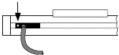
- Place the proximity sensor on DGC-8/12 as follows:
| Position | SME-10/SMT-10F-KL (-SL) | SME-10/SMT-10F-KQ (-SQ) |
| End position left (“L” → Fig. 12) | Cable exit to cylinder centre necessary | Fastening screw faces end cap |
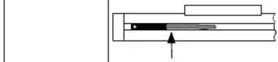 |  | |
| End position right (“R” → Fig. 12) | Fitting position, any | Fitting position, any |
Fig. 15
In this way, you take into consideration the fact that the switching solenoid is arranged asymmetrically (left) on the internal slide.
In case of continuous signal:
- Check whether the proximity switch has been fitted the right way round.
Laying the cables for the proximity switches:
- Note that the cables for the proximity switches can be passed through the groove.
5.4 Installation of accessories
- Use the grooves as per Fig. 16 for fastening the accessories.
S = Groove for proximity switches (sensors)
N = Groove for mounting attachments
DGC-8 DGC-12 DGC-18 DGC-25

DGC-32 DGC-40 DGC-50 DGC-63
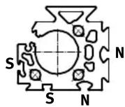


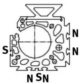
Fig. 16
- Use slot covers to avoid dirt in the sensor grooves (S) of the DGC-18 ... 63.
6 Commissioning
6.1 Commissioning the complete system
- Slowly pressurise the complete system. In this way you will prevent sudden uncontrolled movements.
For slow start-up pressurisation, use on-off valve HEL.
6.2 Preparing for commissioning
With effective loads or at high and medium slide speeds:
- Use the configuration tool “DGC-QuickCalc” for pneumatic drives in the download area www.festo.com
- Use cushioning elements of sufficient size.
Without external cushioning devices the DGC will withstand maximum speeds and work loads as per catalogue specifications.

Warning
Without external cushioning devices the DGC may be damaged if the maximum values specified in the catalogue are exceeded.
- Even in the event of faults, the limit values must not be exceeded.
Before each commissioning and in operation:

Warning
Within the positioning range, make sure that
- nobody can reach into the path of the movable components (e.g. by providing a protective guard).
– there are no objects in the positioning path.
It should not be possible to touch the DGC until the mass has come to a complete standstill.

Fig. 17
For DGC-...-G/GF:
- Remove the protective cover from the guide rail.
6.3 Carrying out commissioning
- Close the one-way flow control valves
– for both sides at first completely,
– then open one rotation.
Using the internal end position cushioning PPV:
-
Close the adjusting screws for the internal end position cushioning PPV
– first close completely,
– then open one rotation. -
Pressurise the DGC as follows:
– At first on both sides simultaneously. The slide will then move slightly to a centre of equilibrium.
- Then exhaust the DGC on one side. In this way you can avoid peak loadings on the DGC and in the compressed air network.
- Start a test run.
natural_image
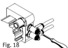
Illustration of a mechanical device with a tool and circular components, labeled as Fig. 19 (no text or symbols on the device itself)- Check whether the speed of the slide must be modified.
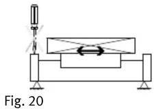
Mass geometries with projection:

Warning
Danger of collision
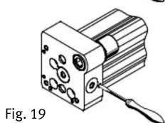
- Note that the adjusting screws of the DGC may only be turned when the slide is at a stand.
- Open up the one-way flow control valves slowly until the desired slide speed is reached.
- Open the adjusting screws for the internal end position cushioning. The slide should reach the end position without striking hard against it or bouncing back.
Accurate adjustment of the stroke:

Warning
The DGC will be damaged if it is operated without the stop sleeve (H) and the locking nut (K).
- Fit the cushioning components together only with the stop sleeve (H) and the lock nut (K).
- Loosen locking nut (K).
- Screw the cushioning element in or out.
DGC-...(-GP) with elastomer shock absorber
DGC-...-YSR(W) with shock absorber

Fig. 21

Note
- For reasons of stability, distance d from Fig. 21 must not exceed the values in the following table:
Distance d [mm]
| DGC- | 8 12 | 18 | 25 | |
| G/GF/KF-P/PPV | 11.3 ... 16.3 | 12.7 ... 17.7 | 13.8 15.8^1) | 21.1 25.1^1) |
| GP-P/PPV | - | - | 16.9 18.9^1) | 23.6 27.6^1) |
| GF-YSR(W) | 12.8 ... 22.8 | 14 ... 24 | 14.5 ... 24.5 | 22.5 ... 32.5 |
| KF-YSR(W) | 12.8 ... 22.8 | 14 ... 24 | 14.5 ... 24.5 | 22.5 ... 32.5 |
Distance d [mm]
| DGC- | 32 | 40 | 50 | 63 |
| G/GF/KF-P/PPV | 25.2 30.2^1) | 28.7 33.7^1) | 28.7 33.7^1) | 38.8 43.8^1) |
| GP-P/PPV | 25.2 30.2^1) | 34.7 39.7^1) | – | – |
| GF-YSR(W) | 27.3 37.3 | 31 41 | 31 56 | 41 76 |
| KF-YSR(W) | 27.3 52.3 | 31 56 | 31 56 | 41 76 |
1) Restriction: Additional masses and speed must be reduced.
Fig. 22
- Tighten the locking nuts (K) with the following tightening torque.
Tightening torques [Nm]
| DGC- | 8/12 | 18 | 25 | 32 | 40 | 50 | 63 |
| G-P/YSR(W) 2 - | |||||||
| GF-YSR(W) | - | 3 | 5 | 8 | 20 | 35 | 60 |
| KF-YSR(W) | 2 | 5 | 20 | 20 | 35 | 35 | 60 |
Fig. 23
If the work load or dynamics are modified:
- Check whether other cushioning components are necessary.
7 Service and maintenance
Maintaining the band system:
- Clean the band system if required with a soft cloth.
- Avoid cleaning agents which will damage the band system which is made of PU. Excessive friction or the use of grease-solvent cleaning agents (e.g. soap suds) will damage the grease layer.
- Lubricate the surface of the band system if it no longer has a layer of grease. Grease type: LUB-KC1 (LUB-E1 for DGC-...-H1).
Lubricating the guides of types G and GF:
- Lubricate the guide rail if it no longer has a layer of grease, but at the latest: - every 3000km or every 3 years. Grease type: LUB-KC1 (for DGC-8-G/GF) - every 1000km or every 2 years. Grease type: LUB-E1 (for DGC-...G/GF-H1)
- Note that lubrication must be undertaken more often:
- if the environment is dusty and contaminated
– with work strokes of < 50 mm
- ambient temperatures >40^ .
The remaining sizes of types G/GF do not require any maintenance (relubrication however is permitted).
Lubricating the guide of type KF:
The lubrication intervals S_int depend on the load of the guide.
- Calculate the load comparison factor f_v with the aid of the formula for combined loads ( Technical data) and determine the lubricating interval S_int from Fig. 24.
- Always lubricate the DGC at the latest every 3 years (every 2 years for the DGC-...-KF-...-H1).

line
| N | DGC | DGC-H1 | |------|-------|--------| | 0.2 | 12000 | 12000 | | 0.6 | 8000 | 7000 | | 0.8 | 6000 | 5000 | | 1.0 | 2000 | 1500 |- Note that lubrication must be undertaken more often:
- if the environment is dusty and contaminated
– with work strokes of < 50 mm or > 2000 mm
- at speeds of > 2 m/s
– in ambient temperatures of >40^ .
- Lubricate the roller bearing through the holes on both sides of the slide. For this purpose use a grease gun with a pointed nozzle or alternatively a disposable syringe with needle.
Fig. 25
Permitted grease types:
DGC-8/12-KF: Gearmaster LXG 00 (Fuchs Lubritech GmbH)
DGC-18 ... 63-KF: Rhenus Norlith STM 2 (Rhenus Lub GmbH & Co. KG)
DGC-8 ... 63-KF-H1: ELKALUB VP 874 (Chemie-Technik)
- Push the slide backwards and forwards during lubrication.
Otherwise the grease cavities will not be filled to an equal extent.
Alternatively, Festo offers a service inspection which includes lubrication.
Otherwise the DGC does not require any maintenance.
8 Repair
- Recommendation: Return the product to our repair service for overhaul. This ensures that special attention will be paid to the necessary fine adjustments and inspections.
- Information on spare parts and aids can be found under: www.festo.com/spareparts
Replacing cushioning elements:
- Note the section “Accurate adjustment of the stroke” in the chapter “Commissioning”.
9 Accessories
Please select the appropriate accessories from our catalogue
→ www.festo.com/catalogue/DGC
10 Eliminating malfunctions
| Malfunction Possible cause Remedy | ||
| Uneven movement of the slide | One-way flow control valve not fitted correctly | If possible reduce the exhaust (not the supply air) |
| Guide rail not greased Lubricate guide rails in accordance with chapter “Care and maintenance” | ||
| Faults in position scanning | Ferritic parts in the vicinity of the proximity sensor | Use parts made of non-magnetic materials or observe minimum distances (→ 5.3. Installing the electric components) |
| Heavy leakage | Cylinder is distorted | Fasten the cylinder to a flat base. |
| Seal worn Replace worn parts: | - Yourself with wearing parts kit- By returning to Festo for repairs | |
| Sealing band pressed in/ sucked in | When the linear drive is unpressurised, move the slide twice manually through the entire stroke (if necessary, push fixed stops into the end position) | |
| Avoid vacuum in the piston chamber (e.g. move the unpressurised slide slowly) | ||
| Cylinder does not reach the desired speed | Air volume not sufficient | - Select tubing with larger diameter- Switch volume upstream |
| High friction or counteracting force | Observe maximum limits | |
11 Technical data
| DGC- | 8 | 12 | 18 | 25 | 32 | 40 | 50 | 63 | |
| Pneumatic connection | DGC | M5 | G 1/8 | G1/4 | G3/8 | ||||
| DGC-N | M5 suitable for 10-32 UNF | 1/8 NPT | 1/4 NPT | 3/8 NPT | |||||
| Mode of operation | Double-acting | ||||||||
| Mounting position | Any | ||||||||
| Operating medium | Compressed air in accordance with ISO8573-1:2010 [7:::-] | ||||||||
| Operating pressure | [bar] | 2.5 ... 8 | 2 ... 8 | 1.5 ... 8 | |||||
| Ambient temperature | [°C] | -10 ... +60 | |||||||
| +5 ... +60 (DGC-8-G) | |||||||||
| Theoretical force at 6 bar | [N] | 30 | 68 | 153 | 295 | 483 | 754 | 1178 | 1870 |
| Speeds (min ... max) | [m/s] | 0.15 ... 1 | 0.1 ... 1.2 | 0.05 ... 3 | 0.04 ... 3 | 0.03 ... 3 | 0.02 ... 3 | ||
| Cushioning length PPV | [mm] | - | 16.5 | 15.5 | 17.5 | 29.5 | 29.8 | 31.1 | |
| Cushioning | P | Flexible cushioning rings/pads at both ends | - | ||||||
| PPV | - | Pneumatic cushioning, adjustable at both ends | |||||||
| YSR | Shock absorber, hard characteristic curve | ||||||||
| YSRW | Shock absorber, progressive characteristic | ||||||||
| Max. energy | → For diagrams, see catalogue specifications | ||||||||
| Note on materials | KF | Free of copper and PTFE | |||||||
| Materials | Scraper, band reverser, cover: | Polyacetal/polyamide | |||||||
| Piston seal, cushioning seal, sealing band, cover band: | Polyurethane | ||||||||
| Stops: | Steel, corrosion resistant/coated | ||||||||
| G | End cap, cover, slide: | Aluminium, coated/polyamide | |||||||
| GF | Slide: | Aluminium, anodised | |||||||
| G/GF | Cylinder profile, guide rail: | Aluminium, anodised | |||||||
| KF | Guide rail, slide: | Steel, corrosion resistant/coated | |||||||
Fig. 27
Permitted force and torque loading
| DGC- | 8 | 12 | 18 | 25 | 32 | 40 | 50 | 63 | |
| G | Fymax [N] | 150 | 300 | 70 | 180 | 250 | 370 | 480 | 650 |
| Fzmax | 150 | 300 | 340 | 540 | 800 | 1100 | 1600 | 2000 | |
| Mxmax [Nm] | 0.5 | 1.3 | 1.9 | 4 | 9 | 12 | 20 | 26 | |
| Mymax | 2 | 5 | 12 | 20 | 40 | 60 | 150 | 150 | |
| Mzmax | 2 | 5 | 4 | 5 | 12 | 25 | 37 | 48 | |
| GF | Fymax [N] | - | - | 440 | 640 | 900 | 1380 | 1500 | 2300 |
| Fzmax | 540 | 1300 180 | 0 2000 | 2870 4460 | |||||
| Mxmax [Nm] | - | - | 3.4 | 8.5 | 15 | 28 | 54 | 96 | |
| Mymax | 20 | 40 | 70 | 110 | 270 | 450 | |||
| Mzmax | 8.5 | 20 | 33 | 54 | 103 | 187 | |||
| KF | Fymax [N] | 300 | 650 | 1850 | 3050 | 3310 | 6890 | 6890 | 15200 |
| Fzmax | 300 | 650 | 1850 | 3050 | 3310 | 6890 | 6890 | 15200 | |
| Mxmax [Nm] | 1.7 | 3.5 | 16 | 36 | 54 | 144 | 144 | 529 | |
| Mymax | 4.5 | 10 | 51 | 97 | 150 | 380 | 634 | 1157 | |
| Mzmax | 4.5 | 10 | 51 | 97 | 150 | 380 | 634 | 1157 | |
Formula for combined loadings:
| f_v = |Mx|Mx_max + |My|My_max + |Mz|Mz_max + |Fy|Fy_max + |Fz|Fz_max ≤ 1 |

Fig. 28
- Note
- Function and application
- Transport and storage
- Requirements for product use
- Installation
- Fitting mechanical components
- Fitting pneumatic components
- Warning
- Installing the electric components
- Installation of accessories
- Commissioning
- Commissioning the complete system
- Preparing for commissioning
- Carrying out commissioning
- Service and maintenance
- Repair
- Accessories
Brand : Festo
Model : DGC-8
Category : Vérin pneumatique linéaire