
BPSE240V47AOA - Battery CyberPower - Free user manual and instructions
Find the device manual for free BPSE240V47AOA CyberPower in PDF.


| Product Type | Battery (UPS Replacement) |
| Brand | CyberPower |
| Model | BPSE240V47AOA |
| Voltage | 24 V |
| Capacity | 47 Ah |
| Chemistry | Sealed Lead-Acid (VRLA) |
| Dimensions (W x H x D) | 7.2 x 3.4 x 6.5 inches |
| Weight | 30 lbs |
| Terminal Type | Faston Tab (0.250") |
| Replacement for | Select CyberPower UPS models |
| Usage | Provides backup power during outages |
| Maintenance | Sealed, maintenance-free |
| Safety Features | Spill-proof, overcharge protection |
| Recyclability | Recyclable lead-acid battery |
Frequently Asked Questions - BPSE240V47AOA CyberPower
User questions about BPSE240V47AOA CyberPower
0 question about this device. Answer the ones you know or ask your own.
Ask a new question about this device
Download the instructions for your Battery in PDF format for free! Find your manual BPSE240V47AOA - CyberPower and take your electronic device back in hand. On this page are published all the documents necessary for the use of your device. BPSE240V47AOA by CyberPower.
USER MANUAL BPSE240V47AOA CyberPower
natural_image
Line drawing of a rectangular industrial machine with wheels and a perforated side panel (no text or symbols)BPSE240V47A
BPSE240V47AOA
User's Manual
K01-C000048-03
SAFETY
This manual contains important instructions. Please read and follow all instructions carefully during installation and operation of the unit. Read this manual thoroughly before attempting to unpack, install, or operate the Battery modules.
● CAUTION! The UPS unit must be connected to a grounded AC power outlet with fuse or circuit breaker protection. The Battery modules grounded are through the UPS.
- CAUTION! The battery can power hazardous components inside the unit, even when the AC input power is disconnected.
- CAUTION! To prevent the risk of fire or electric shock, install in a temperature and humidity controlled indoor area, free of conductive contaminants. (Please see specifications for acceptable temperature and humidity range).
- CAUTION! (No User Serviceable Parts): Risk of electric shock, do not remove cover. No user serviceable parts inside. Refer servicing to qualified service personnel.
● CAUTION! (Non-Isolated Battery Supply): Risk of electric shock, battery circuit is not isolated from AC power source; hazardous voltage may exist between battery terminals and ground. Test before touching.
● CAUTION! Wiring must be done by qualified personnel.
● CAUTION! DO NOT USE WITH OR NEAR AQUARIUMS!
To reduce the risk of fire, do not use with or near aquariums. Condensation from the aquarium can come in contact with metal electrical contacts and cause the machine to short out.
● CAUTION! Do not dispose of batteries in fire as the battery may explode.
- CAUTION! Do not open or mutilate the battery, released electrolyte is harmful to the skin and eyes.
● CAUTION! A battery can present a risk of electric shock and high short circuit current. The following precaution should be observed when working on batteries
- Remove watches, rings or other metal objects.
- Use tools with insulated handles.
● CAUTION! Make sure everything is turned off and disconnected completely before conducting any maintenance, repairs or shipment.
● CAUTION! Connect the Protection Earth (PE) safety conductor before any other cables are connected.
● DO NOT INSTALL THE UNIT WHERE IT WOULD BE EXPOSED TO DIRECT SUNLIGHT OR NEAR A STRONG HEAT SOURCE!
● SERVICING OF BATTERIES SHOULD BE PERFORMED OR SUPERVISED BY PERSONNEL KNOWLEDGE OF BATTERIES AND THE REQUIRED PRECAUTIONS. KEEP UNAUTHORIZED PERSONNEL AWAY FROM BATTERIES!
UNPACKING
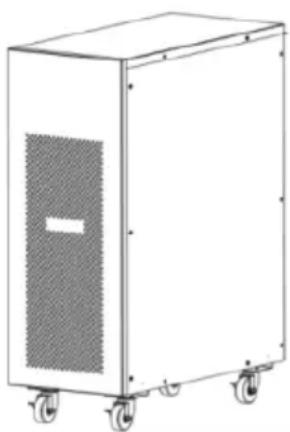
The box should contain the following:
natural_image
Line drawing of a white industrial machine with wheels and a side panel (no text or symbols)Battery Module
 | Battery Cable |
 | User's manual |
BASIC OPERATION
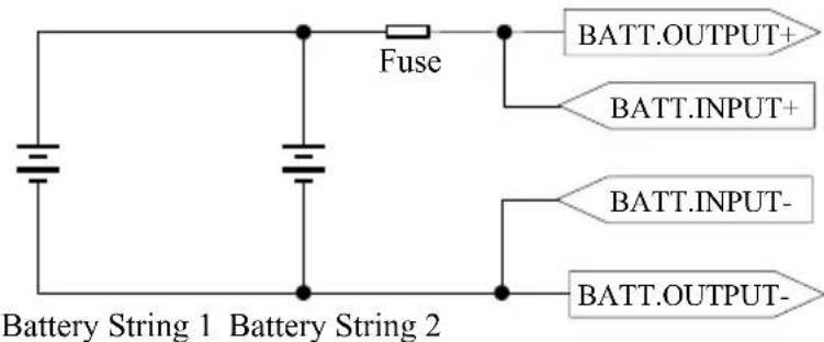
SCHEMATIC
FRONT/REAR PANEL DESCRIPTION
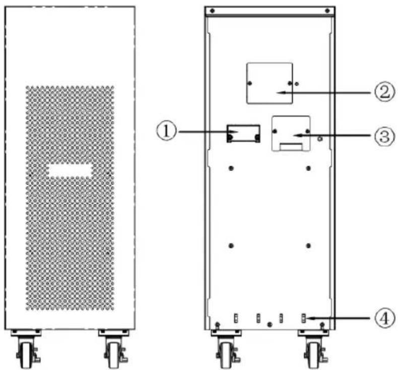
①. Output Connector: Use this output connector to connect the Battery module
and the Power module.
②. On-board Replaceable Fuse Cover: Replaceable fuse is accessible from the rear panel. It must be done by qualified personnel.
③.Battery input Terminal Block: Use this input Terminal Block to daisy chain the next Battery module.
④.Self- locking Frame
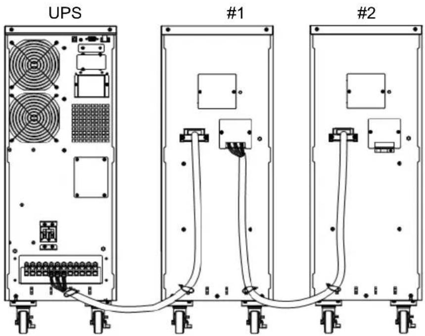
CONNECTION#1: POWER MODULE(UPS) WITH ONE BATTERY MODULE
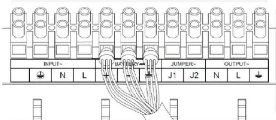
Step 1: Connect the Battery Cable to the Power module and ensure the polarity is right.
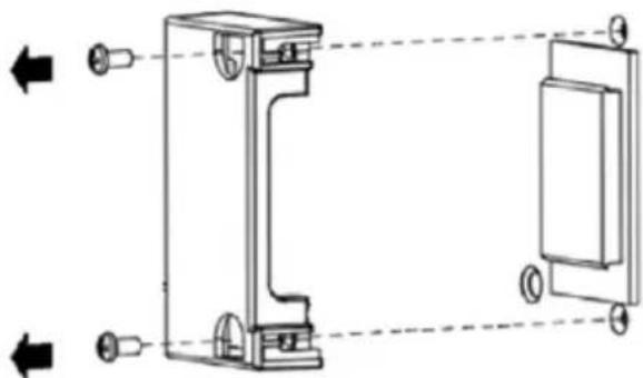
Step 2: Loosen the screws to remove the battery cable retention bracket of the Battery module.
natural_image
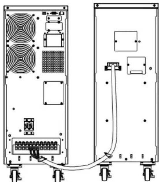
Technical line drawing of a mechanical assembly with two views (top and side), no text or symbols presentStep 3: Connect the Battery Cable to the Battery module.
natural_image
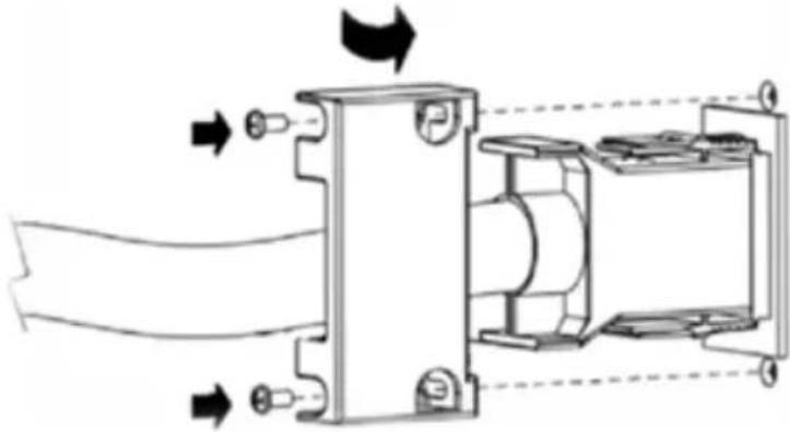
Technical diagram of two server rack units with ventilation fans and connected cables (no text or symbols)Step 4: Rotate the battery cable retention bracket and tighten the screws to fix battery cable.
natural_image
Technical diagram of a mechanical assembly with directional arrows indicating motion or flow (no text or symbols present)CONNECTION#2: POWER MODULE(UPS) WITH MULTIPLE BATTERY MODULES
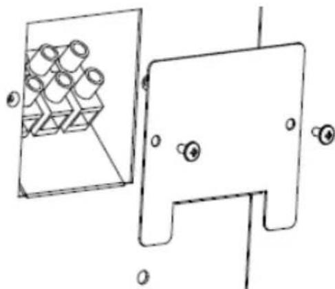
Step 1: Loosen the screws to remove the input Terminal Block Cover of the #1 battery module.
natural_image
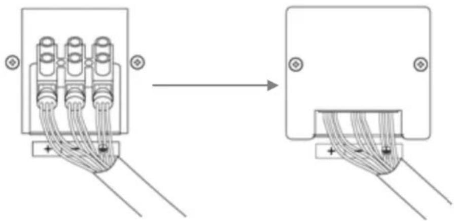
Technical line drawing of a mechanical component with internal components and mounting holes (no text or symbols)Step 2: Connect the Battery Cable to the battery input Terminal Block and ensure the polarity is right, then retighten the Block Cover.
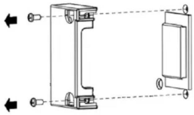
Step 3: Loosen the screws to remove the battery cable retention bracket of the #2 battery module.
natural_image
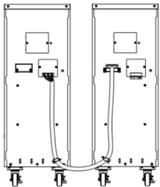
Technical line drawing of a mechanical bracket assembly with two views (left and right), no text or symbols present.Step 4: Connect the #1 Battery module to the #2 Battery module.
1
2
natural_image
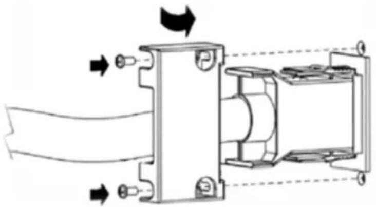
Pure electrical circuit lines without any symbolsStep 5: Rotate the battery cable retention bracket and tighten the screws to fix battery cable.
natural_image
Technical diagram of a mechanical assembly with directional arrows indicating flow or movement (no text or symbols present)Step 6: Connect the #1 Battery module to the Power module. (Refer to above steps of connection#1)
TECHNICAL SPECIFICATION
| Model | BPSE240V47A | BPSE240V47AOA |
| Battery | ||
| Sealed Maintenance Free Lead Acid Battery | 12V / 7Ah x20pcs x2sets | 12V / 9Ah x20pcs x2sets |
| Rated Battery Voltage | 240Vdc | |
| Overload Protection | Fuse | |
| Physical | ||
| Maximum Dimensions (HxWxD) (mm) | 718x260x550 | |
| Weight (kg) | 105 | 127 |
| Environment | ||
| Operating Temperature | 0°C to 40°C | |
| Relative Humidity | 0 to 90%(Non-condensing) | |
CyberPower Systems Inc.
www.cyberpower.com
6F, No. 32, Sec. 1, Chenggong Rd., Nangang District, Taipei 115, Taiwan
Entire contents copyright ^® 2013 CyberPower Systems Inc., All rights reserved. Reproduction in whole or in part without permission is prohibited. PowerPanel ^® Business Edition and PowerPanel ^® Personal Edition are trademarks of CyberPower Systems Inc.

Brand : CyberPower
Model : BPSE240V47AOA
Category : Battery