BPE240V50ART3US - Battery CyberPower - Free user manual and instructions
Find the device manual for free BPE240V50ART3US CyberPower in PDF.

User questions about BPE240V50ART3US CyberPower
0 question about this device. Answer the ones you know or ask your own.
Ask a new question about this device
Download the instructions for your Battery in PDF format for free! Find your manual BPE240V50ART3US - CyberPower and take your electronic device back in hand. On this page are published all the documents necessary for the use of your device. BPE240V50ART3US by CyberPower.
USER MANUAL BPE240V50ART3US CyberPower
Reliability. Quality. Value.
User's Manual
BATTERY MODULE
BPE240V30ART3US
BPE240V50ART3US
CyberPower Systems Inc.
www.cpsww.com
K01-0000318-00
OVERVIEW
The CyberPower Battery modules (BPE240V30ART3US / BPE240V50ART3US) support 30A/50A polarized plugs, and are designed for variety of CyberPower UPS systems. When combining with the UPS, the Battery module provides extended runtime with a 240VDC external connection. Additional parallel-connected Battery modules provide the UPS for a longer extended runtime operation.
UNPACKING
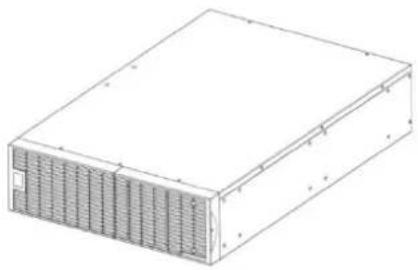
natural_image
Isometric line drawing of a rectangular electronic device with ventilation grilles (no text or symbols)Battery module

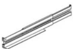
natural_image
Two identical isometric metal bracket diagrams with mounting holes (no text or symbols)Rackmount ears (Stands) (2) * 1 set

Tie plate (1) * 1 set

User's manual

Register card

Flat head screws: M5X8L (8) * 1 set

Pan head screws: M5X12L (12) * 1 set
natural_image
Pure technical line drawing of a mechanical bracket or support structure without any text, numbers, or symbolsRackmount left rail
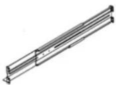
Rackmount right rail

Plastic washers (8) * 1 set

Screw hole dust covers (10) * 1 sets
HARDWARE INSTALLATION
These versatile Battery modules can be mounted in a rackmount or vertical tower orientation. This versatility is especially important to growing organizations with changing needs that value having the option to position a Battery module on a floor or in a rackmount system. Please follow the instructions below for the respective mounting methods.
SAFETY PRECAUTIONS
CAUTION! To prevent the risk of fire or electric shock, only use the supplied hardware to attach the mounting brackets.
RACKMOUNT INSTALLATION
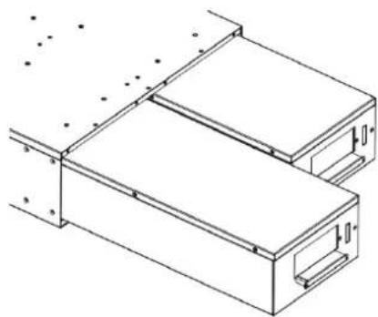
Step 1: Remove the internal battery trays from the Battery module (See page 7)
Step 2: Rackmount ears installation
Attach the two rackmount ears to the Battery module using the provided screws M5X8L*8pcs.

text_image
Technical diagram of an electronic device with labeled components and measurement annotationsStep 3: Rackmount rail Installation
The rails adjust to mount in 48-cm (19-inch) panel racks from 52 to 91.5cm (20.5 to 36 inches) deep. Select the proper holes in the rack for positioning the Battery module in the rack. The Battery module takes up position 1 through position 9.
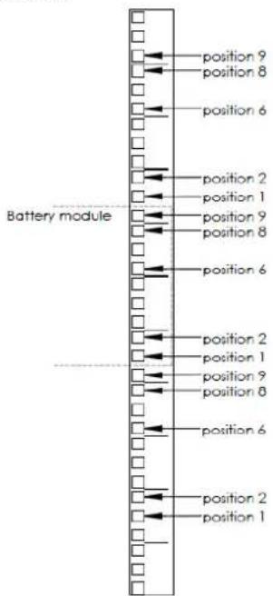
text_image
position 9 position 8 position 6 position 2 position 1 position 9 position 8 position 6 position 2 position 1 position 9 position 8 position 6 position 2 position 1 position 9 position 8 position 6 position 2 position 1Step 4: Adjust rackmount rails to fit your rack
Attach the rackmount rail to your rack with two M5X12L screws and two plastic washers at the front of the rack. (Located in position 1 & position 6) Do not tighten the screws. Adjust the rail size on the rail assembly of your rack. Secure the rail to the rear of the rack with two M5X12L screws and two plastic washers. Tighten all screws at the front and rear of the rail. Once completed, perform the same steps for assembling the other rackmount rail.
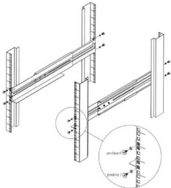
text_image
Technical diagram of a structural frame assembly with labeled positions and componentsPlace the Battery module on a flat stable surface with the front of the unit facing toward you. Secure the Battery module to your rack with four M5X12L screws at the front of the rack. (Located in position 2 & position 8)

text_image
position 6 position 2 position 1 position 6Step 5: Place the internal battery trays back into the Battery module (See page 7)
CAUTION! The Battery module must be installed below the power module.
VERTICAL/TOWER INSTALLATION
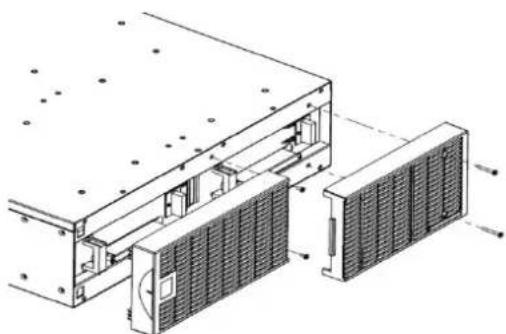
Step 1: Rotate the Multifunction LCD Module
Unscrew the right panel of the power module. Separate the right panel from the UPS. Gently lift the LCD module out. Rotate it to the tower orientation. Reinstall it for a tower configuration.

natural_image
Technical line drawing of a solar panel array with no visible text or symbols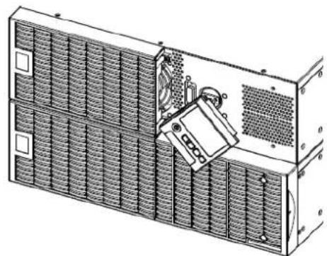
natural_image
Technical line drawing of a multi-panel electronic device with no visible text or symbols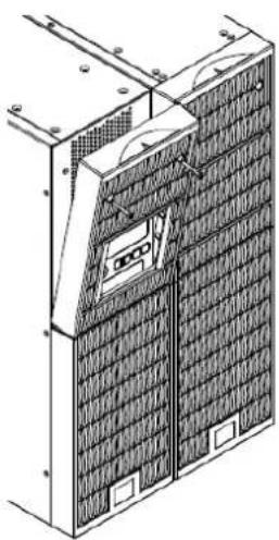
natural_image
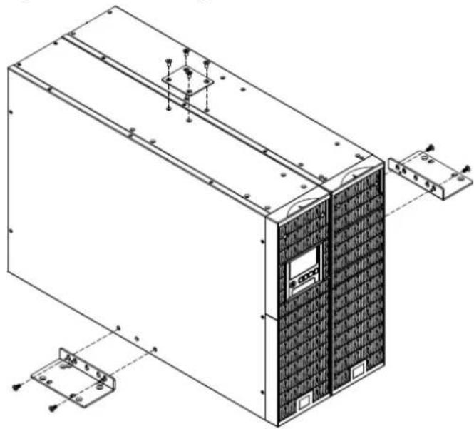
Technical line drawing of a solar panel array with mounting brackets and ventilation ducts (no text or symbols)Step 2: Attach the base stands
Secure the tie bracket with the screws (M5X8*4pcs). Tighten the screws (M5X12*4pcs) of the base stands (rackmount ears) onto the bottom of the power module and the Battery module.
natural_image
Technical line drawing of an industrial server unit with mounting brackets and control panel (no text or symbols)Step 3: Attach dust covers
Insert dust covers into the rackmount ear, screw holes that are not being used.
SAFETY PRECAUTIONS
CAUTION! Installation environment should be in a temperature and humidity controlled indoor area free of conductive contaminants. Do not install this Battery module where excessive moisture or heat is present (Please see specifications for acceptable temperature and humidity range).
CAUTION! Never install a Battery module, or associated wiring or equipment, during a lightning storm.
CAUTION! Do not work alone under hazardous conditions.
CAUTION! In case of the risk of electric shock, do not remove the top cover.
CAUTION! The battery can energize hazardous live parts inside even when the AC input power is disconnected.
BASIC OPERATION
BATTERY MODULE FRONT/REAR PANEL DESCRIPTION
- On-board Replaceable Fuse Cover Replaceable fuse is accessible from the rear panel. It must be done by qualified personnel.
- Input Connector Use this input connector to daisy chain the next Battery module. Remove the connector cover for access.
- Output Cable Use this output cable to connect the Battery module to the Power module or to the next Battery module.

natural_image
Floor plan layout with room layouts and structural grid lines (no text or labels)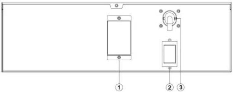
text_image
Diagram of a smartphone panel with labeled components including a screen, switch, and indicator lightsBPE240V30ART3US / BPE240V50ART3US
CONNECTION #1 : POWER MODULE WITH ONE BATTERY MODULE
Step 1: Loosen the two screws to remove the battery cable retention bracket of the power module.
Step 2: Use the output cable of the Battery module to connect the Battery module to the Power module.
Step 3: Rotate the battery cable retention bracket and tighten the two screws to fix battery cable.
Step 4: Use a power cord to plug AC input inlet of the battery module into a wall receptacle.

natural_image
Technical diagram of a mechanical assembly with two components, no visible text or symbols
natural_image
Mechanical assembly diagram showing fluid flow through a valve and housing (no text or labels)
text_image
Technical diagram of an electronic device rear panel with labeled components including power supply, buttons, and fan.BASIC OPERATION
CONNECTION #2 : POWER MODULE WITH MULTIPLE BATTERY MODULES
Step 1: Connect the 1^st Battery module to the Power module using the instructions above.
Step 2: Loosen the two screws to remove the battery cable retention bracket of the 1^st battery module.
Step 3: Use the output cable of the 2^nd Battery module to connect the 2^nd Battery module to the 1^st Battery module.
Step 4: Rotate the battery cable retention bracket and tighten the two screws to fix battery cable.
Step 5: Use a power cord to plug AC input inlet of the 2^nd battery module into AC output outlet of the 1 ^st Battery module.

text_image
Technical diagram showing mechanical assembly with labeled components and directional arrows indicating motion or flow.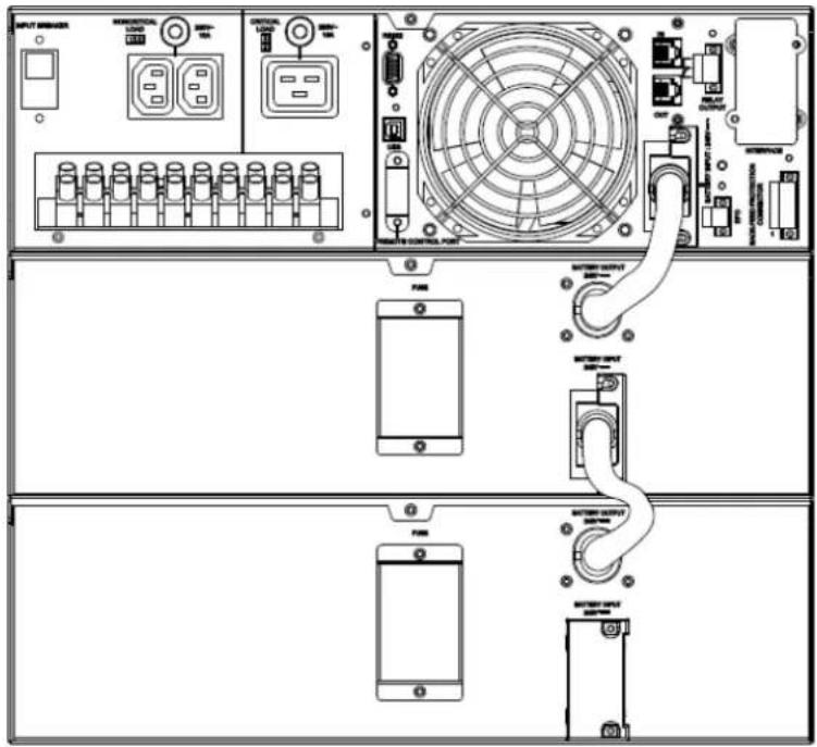
text_image
Technical diagram of a power supply rack with labeled components including controllers, fans, and switchesEXTERNAL BATTERY MODULES CONFIGURATION
External Battery Modules can be configured by the user to display correct estimated battery runtimes.
- Press the "ENTER" button to activate the "MAIN MENU".
- Press the “▲” and “▼” buttons to scroll to the “Configure” option.
- Press the "ENTER" button to select the "Configure" submenu.
-
Press the “▲” and “▼” buttons to scroll to the “EBP Number” option.
-
Press the "ENTER" button to select the "EBP Number" submenu. The first configuration number will be displayed on the second column of LCD display.
-
Press the "▲" and "▼" buttons to scroll through the number of attached Battery modules.
-
Press the "ENTER" button to select the number of Battery modules installed. You may be prompted to save the selection, if so press the "ENTER" button to save the setting.
-
Press the "ESC" button to cancel or return to the previous LCD menu.
| Configure Submenu | Available Settings | Default Settings |
| EBM Number | = [0] [1] [2] [3] [4] [5] [6] [7] [8] [9] [10] | 0 |
MAINTENANCE
Storage
To store your UPS for an extended period, cover it and store with the battery fully charged. Recharge the battery every three months to ensure battery life.
Battery Replacement
Please read and follow the Safety Instructions before servicing the battery. Battery replacement should be performed by trained personnel who are familiar with the procedures and safety precautions. Make a note of the replacement Battery module number.
Safety Precautions
CAUTION! Only use replacement batteries which are certified by CyberPower Systems. Use of incorrect battery type is an electrical hazard that could lead to explosion, fire, electric shock, or short circuit. CAUTION! Batteries contain an electrical charge that can cause severe burns. Before servicing batteries, please remove any conductive materials such as jewelry, chains, wrist watches, and rings.
CAUTION! Do not open or mutilate the batteries. Electrolyte fluid is harmful to the skin/eyes and may be toxic.
CAUTION! To avoid electric shock, turn off and unplug the Battery module from the wall receptacle before servicing the battery.
CAUTION! Only use tools with insulated handles. Do not lay tools or metal parts on top of the UPS or battery terminals.
Replacement Batteries
Please refer to the front side of the Battery module for the model number of the correct replacement batteries. For battery procurement, log onto www.CPSww.com, or contact your local dealer.
Battery Disposal
Batteries are considered hazardous waste and must be disposed of properly. Contact your local government for more information about proper disposal and recycling of batteries. Do not dispose of batteries in fire.
Battery Installation
natural_image
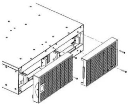
Technical line drawing of a mechanical assembly with internal components and mounting holes (no text or symbols)Step 1: Remove the front panels
natural_image
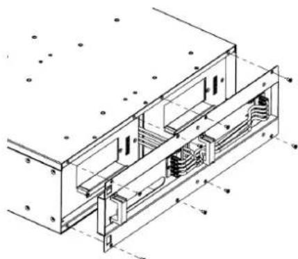
Technical line drawing of a mechanical assembly with no visible text or symbolsStep 2: Remove the retaining screws from the cable protection cover and then remove the cover itself
natural_image
Technical line drawing of a mechanical assembly with two rectangular components and mounting holes (no text or symbols)Step 3: Pull the battery trays out slowly and then put the new battery trays back into the compartment

natural_image
Technical line drawing of a mechanical assembly with internal components and a magnified inset showing internal structure (no text or symbols)Step 4: Insert the battery connectors and tighten the screws of battery retaining cover
natural_image
Technical line drawing of an industrial cooling unit with cooling panel and heat exchanger (no text or labels)Step 5: Install the front panels
CONFORMANCE APPROVALS
| Model | BPE240V30ART3US | BPE240V50ART3US | |
| Configuration | |||
| DC Output Voltage | 240Vdc | ||
| Amperage | 30A | 50A | |
| Physical | |||
| Dimensions | L x W x H = 26 x 17 x 5.2in. (660 x 433 x 132mm) | ||
| Net Weight | 167.2lbs(76Kg) | 171.6lbs(78Kg) | |
| Battery | |||
| Specifications | (20) 12V/7.2AH | (20) 12V/9.0AH | |
| Interface | PP45 | ||
| Sealed, Maintenance Free | Yes | ||
| Hot-Swappable | Yes | ||
| Built-in Charger | Yes | ||
| Environment | |||
| Operating Temperature | 32°F to 104°F (0°C to 40°C) | ||
| Operating Relative Humidity | 0 to 90% Non-Condensing | ||
| Safety | |||
| Conformance Approvals | CE, C-tick | ||
| RoHS | RoHS Compliant | ||
| Warranty | |||
| Product Warranty | 3-year limited warranty, Free Tech Support | ||
TROUBLE SHOOTING
| Problem | Possible Cause | Solution |
| Warning | ||
| BAT Disconnected | Missing battery power. | Check battery connector and battery breaker. |
| Battery Failure | UPS has failed in Battery Test. | 1. Check battery connector and battery breaker.2. Contact technical support to replace the battery. |
| Replace Battery | Battery will soon need to be replaced due to insufficient runtime. | Contact technical support to replace the battery. |
| Fault | ||
| Over Charge | Battery is overcharged. | 1. Remove battery connector and check charger voltage.2. Contact CyberPower for repair. |
| Charger Failure | Charger has failed. | |
CyberPower Systems Inc.
www.cpsww.com
Entire contents copyright ^® 2011 CyberPower Systems Inc., All rights reserved. Reproduction in whole or in part without permission is prohibited. PowerPanel ^® Business Edition and PowerPanel ^® Personal Edition are trademarks of CyberPower Systems Inc.