
VSW 2VGA A - Audio/video converter Extron - Free user manual and instructions
Find the device manual for free VSW 2VGA A Extron in PDF.


| Product Type | Audio/Video Converter & Switcher |
| Brand | Extron |
| Model | VSW 2VGA A |
| Video Inputs | 2 x VGA (15-pin HD) |
| Video Output | 1 x VGA (15-pin HD) |
| Audio Inputs | 2 x Stereo 3.5mm jack |
| Audio Output | 1 x Stereo 3.5mm jack |
| Supported Resolutions | Up to 1920x1200 or 1080p |
| Control | Front panel pushbuttons, RS-232 (optional) |
| Power Supply | External 12 VDC, 500 mA |
| Dimensions (H x W x D) | 1.7 in x 4.3 in x 3.0 in (4.3 cm x 10.9 cm x 7.6 cm) |
| Weight | 0.5 lb (0.23 kg) |
| Enclosure Type | Metal, desktop |
| Operating Temperature | 32°F to 122°F (0°C to 50°C) |
| Compliance | CE, FCC Class A |
| Included Accessories | Power supply, rubber feet |
| Maintenance | Keep dry; clean with soft cloth |
| Repairability | No user-serviceable parts; contact Extron support |
| Warranty | 3 years parts and labor |
Frequently Asked Questions - VSW 2VGA A Extron
User questions about VSW 2VGA A Extron
0 question about this device. Answer the ones you know or ask your own.
Ask a new question about this device
Download the instructions for your Audio/video converter in PDF format for free! Find your manual VSW 2VGA A - Extron and take your electronic device back in hand. On this page are published all the documents necessary for the use of your device. VSW 2VGA A by Extron.
USER MANUAL VSW 2VGA A Extron
VSW 2VGA A • User Guide
The Extron VSW 2VGA A is a compact and economical two-input, one-output VGA switcher with unbalanced stereo audio and 300 MHz (-3 dB) video bandwidth. It accepts two VGA-UXGA, RGBHV, RGBS, RGsB, RsGsBs, component video, or HDTV component video inputs. The switcher has two unbalanced stereo audio inputs and one unbalanced stereo audio output. It also features a buffered local monitor output for Input 1. A front panel toggle switch, a contact closure controller, or the autoswitching option can be used for input selection.
This guide contains information about the Extron VSW 2VGA A switcher. The terms "VSW 2VGA A" and "switcher" are used interchangeably in this manual. The Extron VSW I AAP interface, an optional accessory used when several VSW 2VGA A switchers are daisy chained together, is also discussed.

FCC Class A Notice
This equipment has been tested and found to comply with the limits for a Class A digital device, pursuant to part 15 of the FCC rules. The Class A limits provide reasonable protection against harmful interference when the equipment is operated in a commercial environment. This equipment generates, uses, and can radiate radio frequency energy and, if not installed and used in accordance with the instruction manual, may cause harmful interference to radio communications. Operation of this equipment in a residential area is likely to cause interference. This interference must be corrected at the expense of the user.
NOTES:
- This unit was tested with shielded I/O cables on the peripheral devices. Shielded cables must be used to ensure compliance with FCC emissions limits.
- For more information on safety guidelines, regulatory compliances, EMI/EMF compatibility, accessibility, and related topics, see the Extron Safety and Regulatory Compliance Guide on the Extron website.
Specifications
Product specifications are available on the Extron website, www.extron.com.
Application Diagram
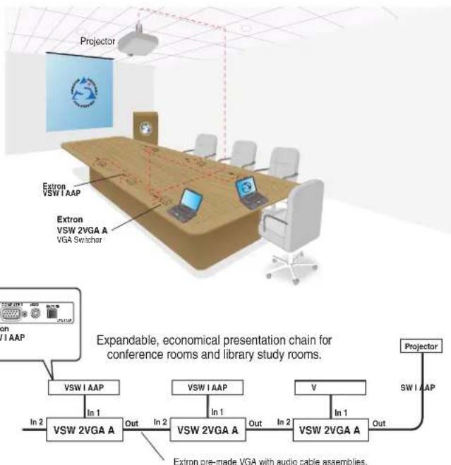
Up to 10 VSW 2VGA A switchers can be daisy chained together with each switcher input separately fed and controlled by an optional accessory interface, the VSW I AAP. Figure 1 is an example of how several such switcher-interface combinations can be daisy chained together in a boardroom environment.
By default, all switchers are set to input 2 as the active input. Therefore, in a daisy chain of switchers the VGA and audio signals flow from one switcher to input 2 of the next switcher in the chain. The switchers are daisy chained in this fashion until the last switcher in the daisy chain outputs to a projector and audio amplifier.
Up to ten switchers can be daisy chained together without any degradation in picture quality. One power supply powers up to five switchers.
flowchart
graph TD
    A["Projector"] --> B["VSW 1 AAP"]
    B --> C["Extron VSW 1 AAP"]
    C --> D["VSW 2VGA A"]
    D --> E["Extron pre-made VGA with audio cable assemblies."]
    E --> F["VSW 2VGA A"]
    F --> G["VSW 2VGA A"]
    G --> H["VSW 2VGA A"]
    H --> I["Projector"]
    style A fill:#f9f,stroke:#333
    style B fill:#ccf,stroke:#333
    style C fill:#cfc,stroke:#333
    style D fill:#fcc,stroke:#333
    style E fill:#cff,stroke:#333
    style F fill:#ffc,stroke:#333
    style G fill:#cfc,stroke:#333
    style H fill:#fcc,stroke:#333
    style I fill:#ffc,stroke:#333
Figure 1. Daisy Chaining the Multiple Switchers
Features
- Inputs — Video on female 15-pin HD connectors, audio on 3.5 mm stereo mini jacks
• Outputs — Video on female 15-pin HD connectors, audio on 3.5 mm stereo mini jacks
• 300 MHz (-3 dB) RGB video bandwidth - Compatible with VGA-QXGA and HDTV component video signals
- Buffered loop-through for input one
• ID bits from inputs 1 and 2 are routed to the output
• Auto-input switching — Automatically switches to the highest-numbered input with an active video signal. - Contact closure remote control
- Front panel toggle switch for input selection
- Through-desk, under-desk, and projector-mountable
• 1U, quarter rack width metal enclosure - External Extron Everlast power supply included — Provides worldwide power compatibility with high-demonstrated reliability and low power consumption
- Extron Everlast Power Supply is covered by a 7-year parts and labor warranty
Installation Overview
To install and set up the VSW 2VGA A for operation, follow these steps:
- Turn all of the equipment off. Make sure that the video and audio sources (computers, stereos, DVD players, or other devices), the VSW 2VGA A, the output devices (projectors, speakers), and the contact closure control device are all turned off and disconnected from the power source.
- If you are going to daisy chain two or more switchers with VSW I AAP control panels, identify the revision of the VSW 2VGA A board (for configuring the VSW I AAPs) and configure the switcher jumpers (see Setting the VSW 2VGA A Jumpers on page 4).
- If desired, mount the switcher (see Mounting the VSW 2VGA A on page 9).
- Attach the cables (see Front Panel Features below and Rear Panel Features on the next page).
- Connect power cords and turn on the devices in the following order: output devices, contact closure controller, VSW 2VGA A switcher, and input devices.
- Select an input using the front panel input toggle switch or the contact closure controller.
- The image should now display, and sound should be audible. If not, ensure that all devices are plugged in and receiving power. Check the cabling and make adjustments as needed. Select a different input to check for a picture and sound.
Front Panel Features

Figure 2. VSW 2VGA A Front Panel Features
A Input 1 LED indicator — This LED lights green whenever Input 1 (video and audio) is selected.
B Input 2 LED indicator — This LED lights green whenever Input 2 (video and audio) is selected.
NOTE: The LEDs also serve as power up indicators. When the switcher is powered up, the selected input LED lights.
C Input select toggle switch — Toggle this switch up to select Input 1. Toggle it down to select Input 2.
D Input 1 video — Input VGA-UXGA, RGBHV, RGBS, RGsB, RsGsBs, component video, or HDTV component video through this female 15-pin VGA connector.
E Input 1 audio (see figure 2 on the previous page) — Input unbalanced stereo audio through this 3.5 mm mini audio jack (see figure 3).
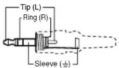
3.5 mm Stereo Plug Connector (unbalanced)
Figure 3. Audio Input Connector
F Input 2 video — Input VGA-UXGA, RGBHV, RGBS, RGsB, RsGsBs, component video, or HDTV component video through this female 15-pin VGA connector.
G Input 2 audio—Input unbalanced stereo audio through this 3.5 mm mini audio jack (see figure 3).
Rear Panel Features

Figure 4. VSW 2VGA A Rear Panel Features
Power connector — Connect the included 12 VDC external power supply to the 2-pole 3.5 mm captive screw connector.
NOTE: One power supply can power up to five switchers (see Power Connection on page 5).
B Loop Thru Input 1 connector — Female 15-pin HD VGA connector for buffered local monitor output from Input 1
Output — Female 15-pin HD VGA connector for output from Input 1 or Input 2. The output video type follows input type and is either VGA-UXGA, RGBHV, RGBS, RGsB, RsGsBs, component video, or HDTV component video.
D Audio Output connector — Unbalanced stereo audio is output from this 3.5 mm mini audio jack (see figure 5).
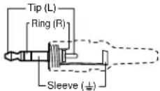
3.5 mm Stereo Plug Connector (unbalanced)
Figure 5. Audio output connector
NOTE If you are daisy chaining, connect the other end of the audio cable to the Audio input 2 connector on the downstream video switcher.
E Contact closure/Autoswitching (Contact/Auto-SW) —
- Contact closure — Connect a contact closure device to this 3.5 mm, 3-pole captive screw connector.
• Pin 1 selects Input 1 when momentarily connected to ground (pin 3).
• Pin 2 selects Input 2 when momentarily connected to ground (pin 3).
• Ground connects to the ground wire (equipment ground).

NOTE: Simultaneously connecting both pins 1 and 2 to ground (pin 3) turns autoswitching mode on.
- Autoswitching —
NOTES:
- Autoswitch mode must be disabled when daisy chaining VSW 2VGA A switchers. If the autoswitch mode is enabled, the switchers cannot be daisy chained.
- RGsB and RsGsBs inputs and outputs occur in manual mode only.
- Autoswitching requires TTL level sync on pin 13 of the 15-pin HD connector.
Pins 1, 2, and Ground when jumpered and shorted together (as shown at right) turn the autoswitching mode on. When the autoswitching mode is on, the switcher automatically switches to the input that has an active sync signal.

If both inputs have an active sync signal present, input 2 is selected, and the input 2 LED indicator lights. If no active sync signal is present, the input 1 LED indicator still lights to indicate that the unit is still powered on.
NOTE: When autoswitch mode is active, both daisy chaining and the front panel input toggle switch are disabled, and the input cannot be manually switched. Any attempt to toggle the switch while the switcher is in this mode results in the flashing of the currently active input LED indicator. Contact closure is also disabled while in autoswitch mode.
Setting the VSW 2VGA A Jumpers
NOTE: If you plan to use the VSW I AAP and create a daisy chain configuration, you must configure the switchers before installing them in a rack or furniture and making connections.
Daisy chaining VSW 2VGA A switchers requires you to check, set or both internal jumpers in the switcher.
- If applicable, disconnect all power to the switcher and any attached devices.
- Remove the two screws on each side of the switcher (see figure 6). Remove the four connector nuts on the front panel of the switcher. Lift the top cover off of the switcher.

Figure 6. Removing the Cover
-
Set the jumpers for the switcher (see figure 7).
-
Set the cover in place and resinstall the screws removed in step 2.
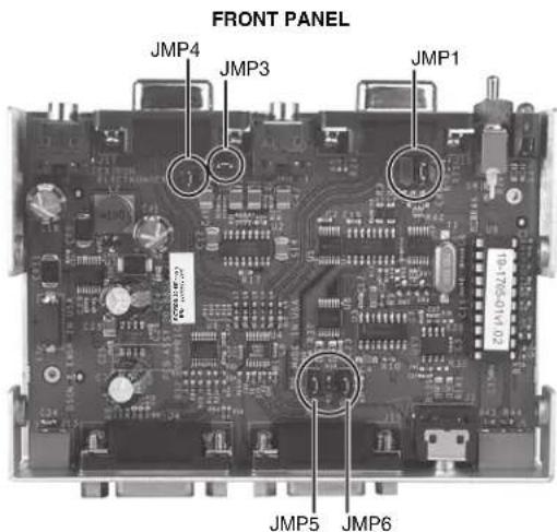
Figure 7. VSW 2VGA A Jumper Locations
There are five jumpers, numbered JMP1, and JMP3 through JMP6, that control daisy chaining on the VSW 2VGA A switcher (see figure 7). Both data and power must be daisy chained from one switcher to another.

All jumpers are set open (disabled) by default.
Open or close the indicated jumpers in the table, as needed, to adjust the appropriate settings.
| Pin 5 - Show Me | Pin 9 - Power | |
| Input 1 | JMP 1 | |
| Input 2 | JMP 3 | JMP 4 |
| Output | JMP 5 | JMP 6 |
Figure 8. Jumper Positions
These jumpers enable or disable VGA connector pin 5 (control) and VGA connector pin 9 (power) of the switcher inputs and outputs.
- Close (install) the jumper for VGA connector pin 5 to daisy chain data to the next switcher.
- Close (install) the jumper for VGA connector pin 9 to daisy chain power to the next switcher (see Using the VSW I AAP on page 6 and Daisy Chain Configuration on page 7).
NOTE: When the switchers are not daisy chained together or used with the VSW I AAP, all jumpers should be in the default (open) position.
Power Connection
One power supply can power up to five daisy chained switchers. Additional switchers require one or more power supplies (see Daisy Chain Configuration on page 7).
Figure 9 shows how to wire the power connector.
CAUTION: The DC output cables must be kept separate from each other while the power supply is plugged in. Remove power before wiring.
Figure 9. Wiring the Power Connector
ATTENTION:
NOTE: Do not tin the stripped power supply leads before installing the captive screw connector. Tinned wires are not as secure in the captive screw connectors and could be pulled out.
NOTE: The maximum number of switchers that can be daisy chained is limited by several factors: power consumption, cable lengths, and the overall distortion of the video and audio signals.
Operation
Apply power and the input signals. The video and audio output connectors, including the Loop Thru Input 1 connector, should output signals.
Input Selection
There are three ways to select between Input 1 and Input 2:
- Toggle the front panel input select switch up (Input 1) or down (Input 2).
- Use the rear panel contact closure capability.
- Press the Show Me button on the VSW I AAP to select the input on the connected VSW 2VGA A switcher.
Using the VSW I AAP
The VSW I AAP can be used on the inputs of a single switcher or on the inputs of multiple switchers in a daisy chain configuration.
Setting the VSW I AAP jumpers
A jumper on the VSW I AAP may need to be shifted from jumper J6 (the default position) to J5, depending on the application (see figure 10).
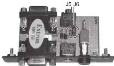
| Jumper installed | Switcher compatibility |
| J6 | VSW 2VGA A (Input 1) |
| J5 | VSW 2VGA A (Input 2) |
Figure 10. VSW I AAP Jumpers
Single switcher example
Figure 11 shows an example of a single switcher configuration.

Figure 11. Single Switcher Configuration
Press the Show Me button on the VSW I AAP to select the corresponding input on the VSW 2VGA A.
Daisy Chain Configuration
Multiple VSW 2VGA A switchers can be daisy chained together in a loop configuration or a tree configuration.
NOTE: Daisy chaining uses all pins and wires of a standard VGA cable. Not all VGA cables include all pins and wires. Ensure the VGA cable that you use has all 15 pins connected.
Loop configuration
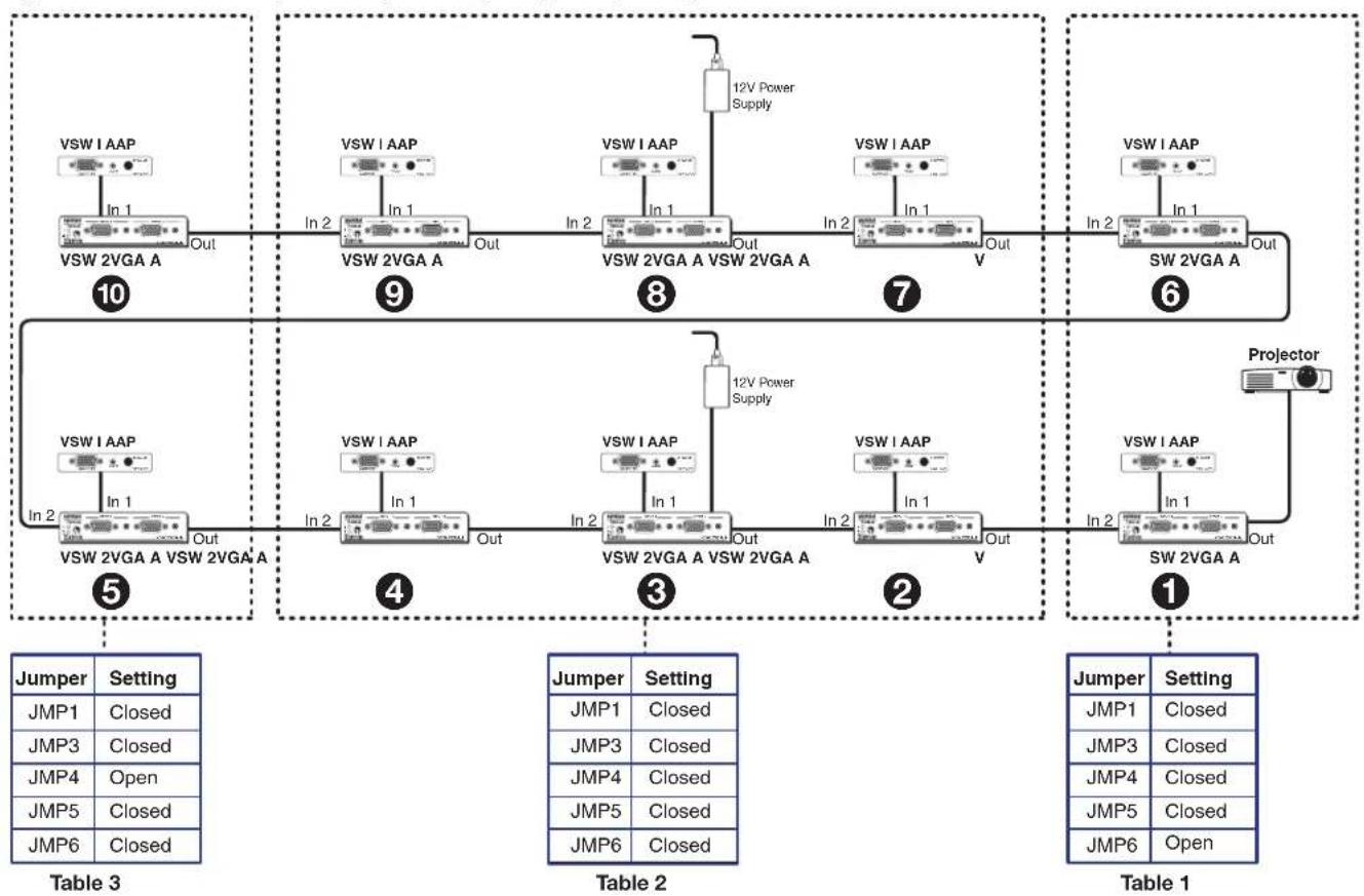
In a loop configuration, the output of each VSW 2VGA A is connected to Input 2 of the next VSW 2VGA A switcher. This repetition of one switcher output to another switcher input can be repeated for up to a maximum of 10 switchers in a daisy chain. The output of the first switcher is connected to a display.
Source signals are connected to Input 1 of each VSW 2VGA A switcher either directly or through the VSW I AAP interface. Select the source by toggling to Input 1 on the VSW 2VGA A front panel (or through contact closure on the rear panel) or by pressing the VSW I AAP Show Me button for the corresponding switcher.
- Up to 10 switchers can be daisy chained in this configuration without any signal degradation.
• A power supply is required for every 5 switchers.
- Configure the jumpers on each VSW 2VGA A according to the example in figure 12 on the next page.
- The VSW I AAP is configured for a loop configuration by default.
NOTE: In a loop configuration, the Show Me feature can be used without a VSW I AAP control panel. Select Input 1 using either the front panel toggle switch (see figure 2, C on page 2) or the rear panel contact closure control (see figure 4, E on page 3) to issue the Show Me control signal.
Loop configuration example
Figure 12 shows an example of daisy chaining using a loop configuration.
flowchart
graph TD
    subgraph Table 3
        A["VSW I AAP"] -->|In 1| B["VSW 2VGA A"]
        B -->|Out| C["10"]
        D["VSW I AAP"] -->|In 2| E["VSW 2VGA A"]
        E -->|Out| F["9"]
        G["VSW I AAP"] -->|In 2| H["VSW 2VGA A"]
        H -->|Out| I["8"]
        J["12V Power Supply"] --> K["VSW I AAP"]
        K -->|In 1| L["VSW 2VGA A"]
        L -->|Out| M["7"]
        N["Projector"] --> O["SW 2VGA A"]
        O -->|In 2| P["6"]
        Q["VSW I AAP"] -->|In 1| R["VSW 2VGA A"]
        R -->|Out| S["5"]
        T["VSW I AAP"] -->|In 2| U["VSW 2VGA A"]
        U -->|Out| V["4"]
        W["VSW I AAP"] -->|In 1| X["VSW 2VGA A"]
        X -->|Out| Y["3"]
        Z["12V Power Supply"] --> AA["VSW I AAP"]
        AA -->|In 1| AB["VSW 2VGA A"]
        AB -->|Out| AC["2"]
        AD["Jumper Setting"] --> AE["JMP1 Closed"]
        AF["JMP3 Closed"] --> AG["JMP4 Open"]
        AH["JMP5 Closed"] --> AI["JMP6 Closed"]
    end
    subgraph Table 2
        AJ["VSW I AAP"] --> AK["VSW 2VGA A"]
        AK -->|In 2| AL["VSW 2VGA A"]
        AL -->|Out| AM["4"]
        AN["VSW I AAP"] --> AO["VSW 2VGA A"]
        AO -->|In 2| AP["3"]
        AQ["VSW I AAP"] --> AR["VSW 2VGA A"]
        AR -->|Out| AS["2"]
        AT["Projector"] --> AU["SW 2VGA A"]
        AU -->|In 2| AV["1"]
        AW["Jumper Setting"] --> AX["JMP1 Closed"]
        AY["JMP3 Closed"]
        AZ["JMP4 Closed"]
        BA["JMP5 Closed"]
        BB["JMP6 Closed"]
    end
    subgraph Table 1
        BC["Jumper Setting"] --> BD["JMP1 Closed"]
        BE["JMP3 Closed"]
        BF["JMP4 Closed"]
        BG["JMP5 Closed"]
        BH["JMP6 Open"]
    end
Figure 12. Loop Configuration
Tree configuration
In a tree configuration, the output of each VSW 2VGA A switcher is connected to Input 1 or Input 2 of the next switcher. This repetition of one switcher output to another switcher input can be repeated for up to a maximum of 10 switchers in a daisy chain. The output of the last switcher is connected to a display.
Source signals are connected to Input 1 and Input 2 of each VSW 2VGA A switcher at the top of the tree through a VSW I AAP interface. Select the source by pressing the VSW I AAP Show Me button for the corresponding switcher.
- Switchers can be daisy chained in this configuration up to 10 levels deep without any signal degradation.
• A power supply is required for each switcher in the chain that has its output connected to Input 1 of the next switcher.
Sources can only be selected and connected to the switcher through the VSW I AAP interface. - Each VSW I AAP must be configured for the tree configuration (see Using the VSW I AAP on page 6 for additional information).
Tree configuration example
Figure 13 shows a simple example of daisy chaining using a tree configuration.

flowchart
graph TD
    A["Projector"] --> B["VSW 2VGA A"]
    B --> C["Input 1"]
    B --> D["Input 2"]
    B --> E["Output"]
    B --> F["12 V Power Supply*"]
    B --> G["Out"]
    H["VSW I AAP"] --> I["1"]
    H --> J["2"]
    H --> K["3"]
    H --> L["4"]
    M["VSW I AAP"] --> N["2"]
    M --> O["3"]
    M --> P["4"]
    Q["VSW I AAP"] --> R["3"]
    Q --> S["4"]
    T["VSW I AAP"] --> U["4"]
    T --> V["Output"]
    W["VSW I AAP"] --> X["4"]
    W --> Y["Output"]
    Z["Internal Jumper Settings"] --> AA["Jumper Setting"]
    AA --> AB["JMP1 Closed"]
    AA --> AC["JMP3 Closed"]
    AA --> AD["JMP4 Closed"]
    AA --> AE["JMP5 Closed"]
    AA --> AF["JMP6 Closed"]
    AG["Jumper Setting"] --> AH["JMP1 Closed"]
    AG --> AI["JMP3 Closed"]
    AG --> AJ["JMP4 Closed"]
    AG --> AK["JMP5 Open"]
    AG --> AL["JMP6 Open"]
    AM["NOTE: * Every switcher connected to Input 1 of another switcher must have its own power supply."]
Figure 13. Tree Configuration
Mounting the VSW 2VGA A
ATTENTION: Installation and service must be performed by authorized personnel only.
NOTE: If you are going to daisy chain two or more switchers with VSW I AAP control panels, identify the revision of the VSW 2VGA A board (for configuring the VSW I AAPs) and configure the switcher jumpers before mounting the switchers (see Setting the VSW 2VGA A Jumpers on page 4).
The VSW 2VGA A can be mounted in a rack, or under or through furniture, using an optional mounting kit available at www.extron.com. When mounting the switcher, take cabling and power availability into consideration. Follow the appropriate mounting procedure on the following pages.
Rack Shelf Mounting
UL rack mounting guidelines
The following Underwriters Laboratories (UL) guidelines pertain to the safe installation of the VSW 2VGA A in a rack.
- Elevated operating ambient temperature — If installed in a closed or multi-unit rack assembly, the operating ambient temperature of the rack environment may be greater than room ambient temperature. Therefore, install the switcher in an environment compatible with the maximum ambient temperature (Tma = +122° F, +50° C) specified by Extron.
- Reduced air flow — Install the equipment in a rack so that the amount of air flow required for safe operation of the equipment is not compromised.
- Mechanical loading — Mount the equipment in the rack so that a hazardous condition is not achieved due to uneven mechanical loading.
-
Circuit overloading — Connect the equipment to the supply circuit and consider the effect that circuit overloading might have on overcurrent protection and supply wiring. Appropriate consideration of equipment nameplate ratings should be used when addressing this concern.
-
Reliable earthing (grounding) — Maintain reliable grounding of rack-mounted equipment. Pay particular attention to supply connections other than direct connections to the branch circuit (e.g. use of power strips).
Rack mounting instructions
- If feet were installed on the bottom of the switcher, remove them.
- Mount the VSW 2VGA A on a rack shelf. On the standard rack shelf, the switcher mounts in one of four locations to the rear of the rack or in one of four locations to the front of the rack.
- Attach the switcher to the rack shelf using two 4-40 x 3/16 inch machine screws. Insert the screws from the underside of the shelf and securely fasten them into diagonally opposite corners, as shown in figure 14.

Figure 14. Mounting the VSW 2VGA A on a Rack Shelf
NOTE: Since the switcher is 1.0 inch high, there will be a gap of 0.75 inch above the switcher.
- Attach the rack shelf to the rack using four 10-32 x 3/4 inch bolts (provided). Insert the bolts through #10 beveled washers, then through the holes in the rack ears and rack, as shown in figure 15.

Figure 15. Mounting the VSW 2VGA A on a Standard 1U Rack Shelf
Under-desk mounting
- Attach the under-desk mounting brackets to the VSW 2VGA A with the four provided machine screws, as shown in figure 16.
- Hold the switcher with attached brackets against the mounting surface. Use a soft pencil to mark the location of holes for screws on the desk or other furniture.
- Drill 1/4 inch (6.4 mm) deep, 3/32 inch (2 mm) diameter pilot holes in the table or desk at the marked screw locations from the underside/inside (concealed side) of the furniture, where the switcher will be located.
- Attach the VSW 2VGA A to the desk with the provided wood screws.

natural_image
Technical line drawing of a rectangular panel with an internal component and mounting holes, showing no text or symbols.Figure 16. Under-desk Mounting Bracket
Through-desk mounting
- Hold the front panel of the switcher against the furniture. Use a soft pencil to mark the rough-in opening on the desk. The opening, 1.125 inch x 4.425 inches (2.8 cm x 11.2 cm) will be slightly larger than the switcher enclosure.
- Cut out the material from the rough-in area with a jigsaw. Check the opening size by inserting the switcher part way through the hole. If needed, use a saw, file, or sandpaper to enlarge the hole. Smooth the edges of the hole with sandpaper.
- Attach the through-desk mounting brackets to the VSW 2VGA A with the four provided machine screws, as shown in figure 17.
- Hold the switcher with attached brackets up against the underside of the desk or table. Use a soft pencil to mark the locations of the holes for the screws that will attach the brackets to the desk.
- Drill 1/4 inch (6 mm) deep, 3/32 inch (2 mm) diameter pilot holes in the desk or table at the marked screw locations. The holes should be drilled from the underside or inside (concealed side) of the furniture, where the switcher will be located.

Figure 17. Through-desk Mounting
- Attach the switcher to the desk or table with the provided wood screws, as shown in figure 17.
- To adjust the height of the switcher within the desk, slightly loosen the screws that attach the brackets to the switcher, adjust the height by sliding the switcher up or down, and retighten the screws.
- VSW 2VGA A • User Guide
- FCC Class A Notice
- NOTES:
- Specifications
- Application Diagram
- Features
- Installation Overview
- Front Panel Features
- Rear Panel Features
- Setting the VSW 2VGA A Jumpers
- Figure 8. Jumper Positions
- Power Connection
- ATTENTION:
- Operation
- Input Selection
- Using the VSW I AAP
- Setting the VSW I AAP jumpers
- Single switcher example
- Daisy Chain Configuration
- Loop configuration
- Loop configuration example
- Tree configuration
- Tree configuration example
- Mounting the VSW 2VGA A
- Rack Shelf Mounting
- UL rack mounting guidelines
- Rack mounting instructions
- Under-desk mounting
- Through-desk mounting
Brand : Extron
Model : VSW 2VGA A
Category : Audio/video converter