MAX 185-253KTL3-X HV - Solar panel Growatt - Free user manual and instructions
Find the device manual for free MAX 185-253KTL3-X HV Growatt in PDF.

User questions about MAX 185-253KTL3-X HV Growatt
0 question about this device. Answer the ones you know or ask your own.
Ask a new question about this device
Download the instructions for your Solar panel in PDF format for free! Find your manual MAX 185-253KTL3-X HV - Growatt and take your electronic device back in hand. On this page are published all the documents necessary for the use of your device. MAX 185-253KTL3-X HV by Growatt.
USER MANUAL MAX 185-253KTL3-X HV Growatt
natural_image
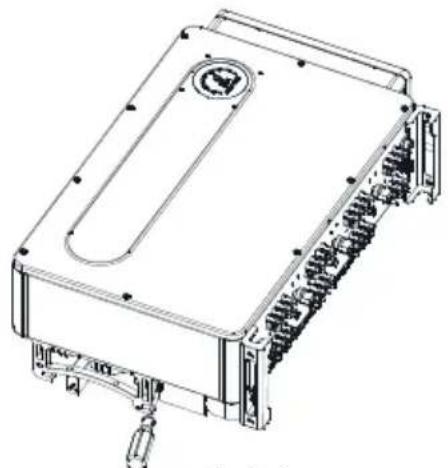
Exterior view of a white GROWATT energy storage device with a control panel and cooling fins (no readable text beyond branding)Installation
&
Operation Manual
List
1 Overview
2 Safety Precautions
3 Product Introduction
4 Unpacking
5 Installation
1.1 Product Overview
1.2 Applicable Personnel
2.1 Safety Overview
2.2 Symbol Conventions
2.3 Safety symbol description
3.1 Appearance
3.2 Basic Data
3.3 Nameplate
3.4 Working Principle
3.5 Inverter Storage
3.6 Grid Types
3.7 AFCI Detection Function
5.1 Basic Installation Requirements
5.2 Installation Environment Requirements
5.3 Moving Requirements
5.4 Wall Mounted Installation
5.5 Installing the Inverter
6 Connecting Cables
7 Commissioning
8 Monitoring
9 System Maintenance
10 Specification
6.1 Connection on AC side
6.2 Connection on DC side
6.3 Connection of Communication Cables
6.4 Inverter demand response modes (DRMS)
6.5 Connecting the Ground Cables
7.1 Commission The inverter
7.2 Operation Mode
7.3 LED display
8.1 Remote Data Monitoring
8.2 Local Data Monitoring
9.1 Routine Maintenance
9.2 Trouble Shooting
11 Decommissioning
12 Quality Assurance
13 Contact
11.1 Disposing Of The MAX 175-253KTL3-X Series Inverter
1 Overview
1.1 Product Overview
This manual will provide detailed product information and installation instructions for users of Shenzhen Growatt New Energy Co., Ltd. (Short as Growatt) MAX 175-253KTL3-X HV series solar inverters. Please read this manual carefully before using this product, and store this manual in a place that is convenient for installation, operation, and maintenance personnel. No further notice if there is any change in this manual.
1.2 Applicable Personnel
Only qualified electrical technicians are allowed to install inverter. With reading through this manual and following all the precautions, qualified electrical technician can properly install MAX 175-253KTL3-X HV serial inverter, finish trouble shooting and communication settings.
If there is any problem during the installation, the installer can either log on www.ginverter.com and leave a message or call consumer service hotline +86 755 2747 1942.
2 Safety Precautions
2.1 Safety Overview
1> Before installation please make sure reading through this manual, any damage cause by improper installation, Growatt reserve the right to disclaim any warranty.
2> All the operations and connections must be done by trained qualified electrical technician.
3> During installation except for terminals, do not touch any inside part of the inverter.
4> All the electrical connections must meet local country's safety regulations.
5> If you need maintenance for this inverter, please contact our local authorized installing and maintenance technician.
6> You must get the local power supplier's permit before connecting this inverter to the grid.
Handle Process:
| WARNING | • The inverter is heavy,please treat with care while handling,in case of crushing injury. |
Installation:
 NOTICE NOTICE | • Before installation,please read through this manual,any damage cause by improper installation,Growatt reserve the right to disclaim any warranty. |
 DANGER DANGER | • Ensure that the inverter is not connected to a power supply and is not power on before installation. |
 WARNING WARNING | Please follow this installation manual as installation condition environment, space and so on.Please install the inverter in a dry and ventilated environment otherwise may affect the performance of the inverter.Please follow the installation procedures in this manual. |
Electrical Connections:
 DANGER DANGER | ·Before electrical connection, please ensure the inverter DC switch is at "OFF" also disconnect AC switch, otherwise the high voltage from inverter may cause life risk.·Only trained authorized electrical technician can do the electric connection also please follow the connection procedures in this manual along with local country's regulations.·High voltage may cause electric shocks and serious injury please do not touch the inverter.·Please do not store inverter in area with flammable and explosive material. |
 WARNING WARNING | ·Each inverter must install one AC breaker; AC breaker is forbidden to share with other inverters·It is forbidden to add load between inverter and breaker.·If the cable is thick, after tightening the cable do not shake it and ensure the cable is well-connected and then start the inverter. Loose connection may cause overheat.·Before connecting between PV panels and inverter please ensure the positive and negative poles are correct connected. |
Maintenance and replacement:
 DANGER DANGER | Must be installed by trained and authorized electrical technician and accurately follow this manual.Please disconnect the DC and AC switch for at least five minutes, all the operations should be carried after power disconnection.If there is PV isolation low alarm, the inverter case may be ungrounded,please do not touch the inverter case.High voltage of inverter may result in electric shock. |
 WARNING WARNING | Do not use air pump to clean the fans, cause it may damage the fans.For better cooling purpose, please regularly clean the fans. |
Other:
 | After you receiving the inverter please check the packing materials for damage,if there is any damage please contact your supplier. |
 WARNING WARNING | The Max PV input voltage should not exceed 1500V.For the disposed inverter,the consumer should dispose it according to local disposal rules for electrical equipment waste. |
2.2 Symbol Conventions
| Symbol | Description |
 DANGER DANGER | Indicates an imminently hazardous situation which,if not avoided, will result in serious injury or death. |
 WARNING WARNING | Indicates potentially hazardous situation which,if not avoided,will result in serious injury or death. |
 CAUTION CAUTION | Indicates potentially hazardous situation which,if not avoided,will result in minor or moderate injury. |
 NOTICE NOTICE | Indicates certain hazardous situation which,if not avoided,will result in property damage. |
 Information Information | Reminds operator to read installation manual before operating or installing inverter. |
2.3 Safety symbol description
| Symbol | Name | Meaning |
 | High Voltage Electric Shock | Inverter operating with high voltage, any operation regarding inverter need to be done by trained and authorized electrical technician. |
 | Burn Warning | Do not touch a running inverter cause it generates high temperature on the case. |
 | Protective Grounding | Connect inverter to grounding bar. |
 | Delay discharge | Residual voltage exists after the inverter is powered off, it takes 5 minutes for the inverter to discharge to the safe voltage. |
 | Read the installation manual | Reminds operator to read installation manual before operating or installing inverter. |
 | DC | Means this terminal is for DC side |
 | AC | Means this terminal is for AC side |
 | CE Mark | The inverter complies with the requirements of the applicable CE guidelines. |
3 Product Introduction
3.1 Appearance
Front view:
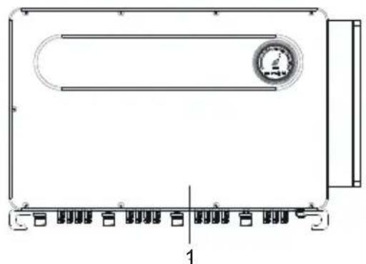
natural_image
Technical line drawing of a rectangular electronic device with internal components and a circular emblem on the top (no text or symbols)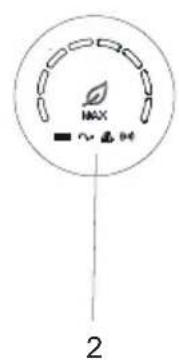
Fig 3.1
Bottom view(Termial):
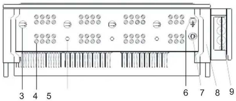
Fig 3.2
Side view:
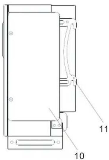
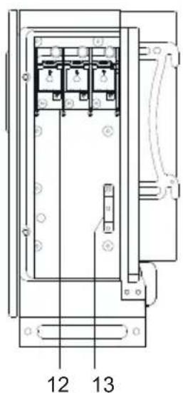
Fig 3.3
| Mark | Description | Mark | Description |
| 1 | Front panel | 8 | Corner guard |
| 2 | LED | 9 | Waterproof silicone pad |
| 3 | DC switch | 10 | AC Junction BOX |
| 4 | PV terminal | 11 | Machine support |
| 5 | Breathing valve | 12 | AC terminal |
| 6 | USB interface | 13 | Ground copper row |
| 7 | COM interface |
Note: For 175-216kW models have 9 MPPTs, For 225-250kW models have 12MPPTs, For 230-253kW models have 15MPPTs.
3.2 Basic Data
| Model | Size(mm) | Weight (kg) | ||
| Width | Height | Thickness | ||
| 175-216K Series Inverter | 1070 | 675 | 340 | 99 |
| 175-216K Series Inverter with package | 1265 | 865 | 510 | 115 |
| 225-250K Series Inverter | 1070 | 675 | 340 | 105 |
| 225-250K Series Inverter with package | 1265 | 865 | 510 | 120 |
| 230-253K Series Inverter | 1070 | 675 | 340 | 109 |
| 230-253K Series Inverter with package | 1265 | 865 | 510 | 125 |
3.3 Nameplate
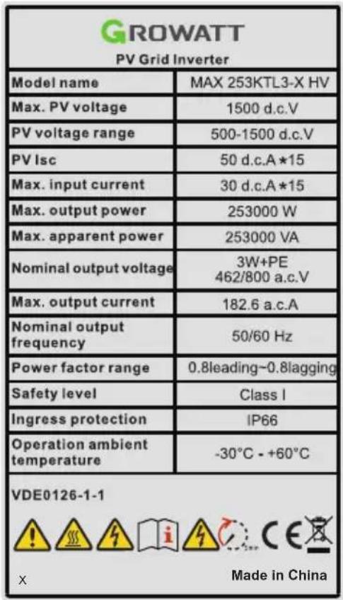
Note: Other models of MAX 175-253KTL3-X HV series share the same label design with MAX 253KTL3-X HV, only with different model name and parameters, detail parameter please refer to specification in Chapter 10.
3.4 Working Principle
The MAX 175-253KTL3-X HV series inverter works as follows:
1>The PV panels gather solar to generate DC power to inverter.
2>With input current detection circuit, it can monitor all the PV panels' working status and use MPPT to track the maximum power point.
3>With inverter circuit change DC power to AC power, and feed power back to grid per grid requirement.
4>With output isolation relay can isolate AC output and grid, if anything goes wrong on either inverter side or grid side, isolation relay can disconnect inverter immediately.
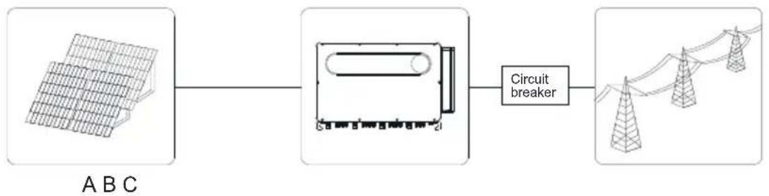
On-grid connection system diagram:
flowchart
graph LR
    A["Grid Data"] --> B["Circuit Breaker"]
    B --> C["Tower Tower"]
Fig 3.4
| symbol | Description | symbol | Description |
| A | PV string | C | Grid |
| B | Inverter |
3.5 Inverter Storage
1>Do not unpack the inverter and store it in a ventilation dry place.
2>Keep the storage temperature at -30 °C- +60°C and humidity at 0-100%.
3>A maximum of three inverters with package can be stacked.
4>If the inverter has been long-term stored, inspections and tests should be conducted by qualified personnel before it is put into use.

After being stored for a month or longer, the inverter's time and date could be wrong, you need set the time and date before using, for more details please refer to Chapter 7.1 inverter commissioning
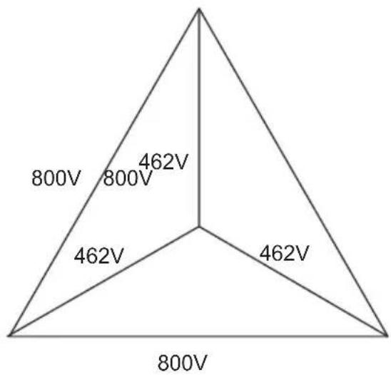
3.6 Grid Types
The MAX 175-253KTL3-X HV seriers inverters connect to the grid like following drawing 3-5:
radar
| Category | Value | |---|---| | Top Left | 800V | | Top Right | 462V | | Bottom Left | 462V | | Bottom Right | 800V |Fig 3.5
3.7 AFCI Detection Function
AFCI (Arc Fault Circuit Interrupter) is a kind of circuit protection device, the main function is to prevent the fire caused by fault arc. The electrical insulation aging, breakage, loose connection, air breakdown caused by air humidity and so on, all of these may cause an electric spark, which is called arc.
The AFCI function of the MAX 175-253KTL3-X HV series inverter is optional, and the detection equipment is assembled inside the inverter. When an arc-drawing condition is detected on the PV input side, the arc current could be detected by the CT assembled on the PV input-side wire. Then the inverter will shut down. Meanwhile, the inverter will display the corresponding fault message and the buzzer will sound, which could help to avoid harm and economic loss to the user.
NOTE: AFCI function is optional.
Unpacking
Checking before installation
1>Before unpacking the inverter, check the outer packing materials for damage.
2>After unpacking the inverter, check that the contents are intact and complete. If any damage is found or any component is missing, contact your supplier.
Package contents:
Package contents:
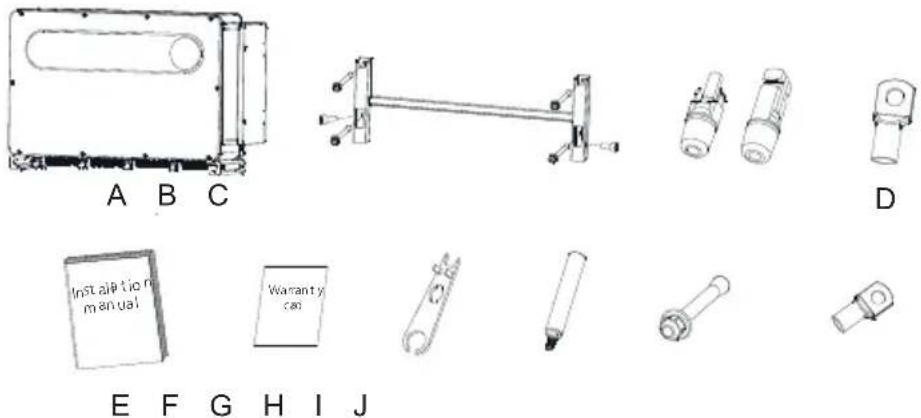
Fig 4.1
| Mark | Descriptions | Number |
| A | Inverter | 1 |
| B | Wall mount | 1 |
| C | PV + terminal, PV- terminal | 30/30 |
| D | AC wiring copper terminal | 3 |
| E | Installation manual | 1 |
| F | Warranty card | 1 |
| G | Removal tool of PV terminal | 1 |
| H | Carrying handle | 4 |
| I | M10*90 Expansion screw | 4 |
| J | DT50-8 Ground terminal | 1 |
5 Installation
 CAUTION CAUTION | To prevent device damage and personal injury, keep balance when moving the inverter because it is heavy.Do not place the inverter with its wiring and signal terminals at the bottom contacting with floor or any other object because the terminals are not designed to support the weight of inverter.When placing inverter on the floor, put foam or paper under the inverter to protect its cover. |
5.1 Basic Installation Requirements
A. Ensure that the installation wall is solid enough to bear the inverter(Inverter weight please refer to installation manual Chapter3, 3.2).
B. There must be enough installation space to fit the size of inverter.
C. Do not install inverter on flammable or heat-intolerant buildings.
D. This inverter is IP 66 protection, you can install it indoor or outdoor.
E. To avoid inverter performance de-rate due to the over heat, please do not expose the inverter under direct sunlight.
F. The installation humidity can be from 0-100%.
G. The surrounding temperature of inverter should be from -30°C - +60°C.
H. Inverter should be installed in a vertically or rear tilted surface, please refer to following drawings.
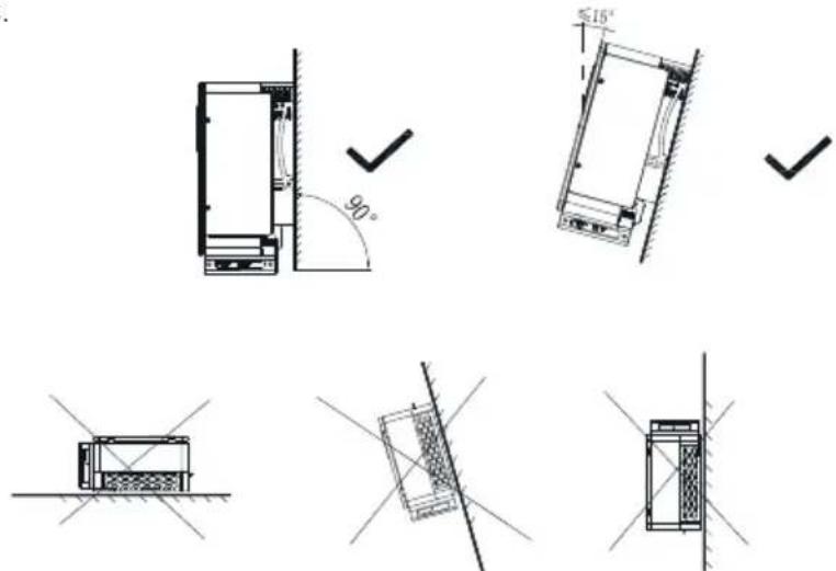
Fig 5.1
- To ensure the inverter can work smoothly and easy for personnel to operate, please notice there is sufficient space for inverter, refer to following drawing.
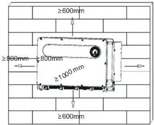
Fig 5.2
J. Do not install inverter close to strong electromagnetic signal.
K. Install the inverter out of children's reach.
5.2 Installation Environment Requirements
A. Although the inverter's protection level is IP 66, to extent inverter lifespan you still need to avoid rain and snow, please refer to following drawings.
Fig 5.3
B. To reduce the de-rate performance of the inverter and extend inverter's life span, we strongly recommend you install an awning, for the distance between an awning and inverter, please refer to following drawing.
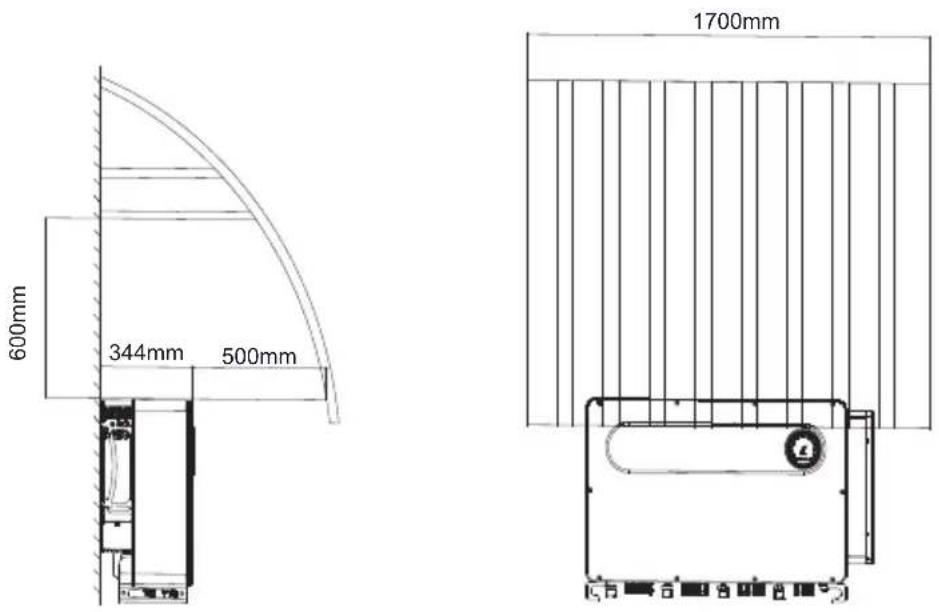
Fig 5.4
C. When you install multiple inverters on one surface, inverters should be installed as following drawing. (Choose one of the two options below).
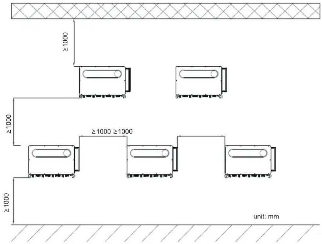
Fig 5.5
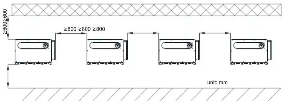
Fig 5.6
D.Do not install inverter into an enclosed space like following drawing.
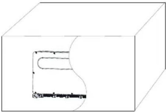
natural_image
3D diagram of a rectangular block with a curved cutout and a small horizontal bar at the bottom (no text or symbols)Fig 5.7
5.3 Moving Requirements
 WARNING WARNING | The inverter is heavy, please move it with care and keep balance to avoid personnel injury.Do not place the inverter with its wiring and signal terminals at the bottom contacting with floor or any other object because the terminals are not designed to support the weight of inverter. |
1> As shown in Fig5-8, 4-6 persons lift the inverter out of package, and then use four carrying handles to move the inverter to installation position.
2> When you are moving the inverter, please keep the balance.
Notice: There will be front and bottom mark on the package.
natural_image
Technical line drawing of a mechanical device housing with internal components and mounting brackets (no text or symbols)Fig 5.8
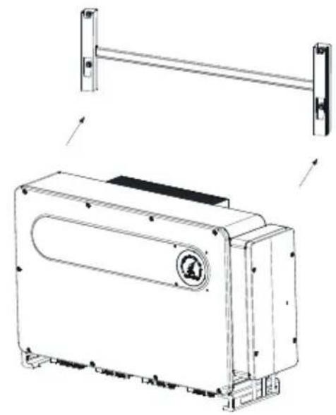
5.4 Wall Mount Bracket Installation
Before install the inverter you need install the wall mount bracket so that the inverter can be firmly installed on the wall.
Wall mount plan:
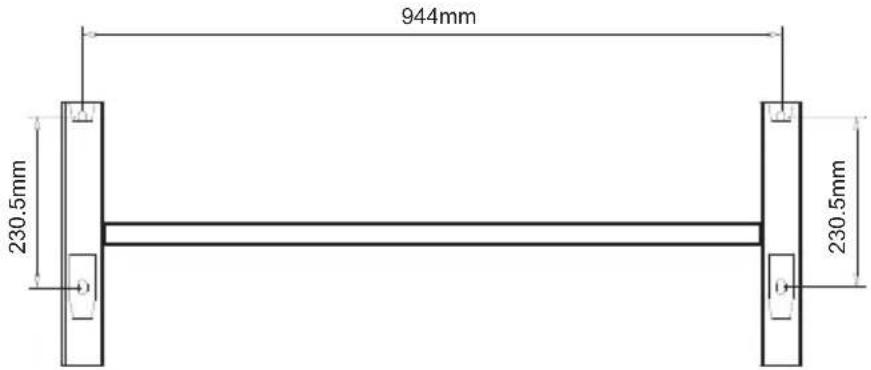
Fig 5.9
1> Use the wall mount plate as a template drill holes on the wall and put in expansion bolts.
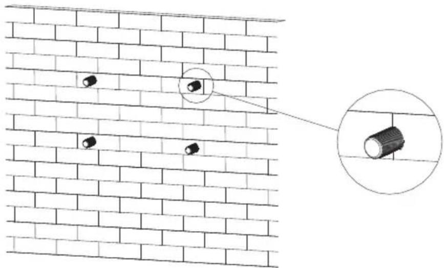
natural_image
Diagram of a brick wall with embedded circular objects and an inset showing a cylindrical object (no text or symbols)Fig 5.10
Notice: Expansion bolt should be installed on solid walls with at least 100mm thickness. 2>Follow the following drawing put the bolt to install the wall mount plate on the wall.
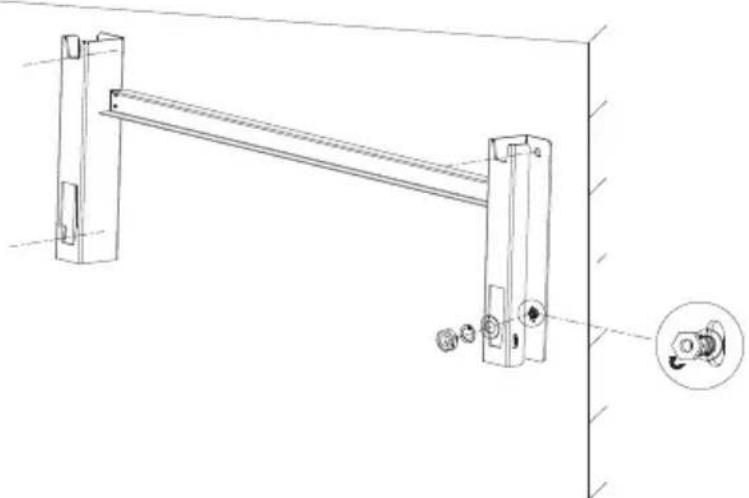
natural_image
Technical line drawing of a mechanical lever assembly with mounting bracket and adjustment knob (no text or symbols)Fig 5.11
Notice: Do not install inverter unless you have confirmed the wall mount plate has been firmly installed on the wall.
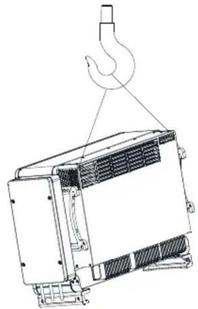
5.5 Installing The Inverter
After the wall mount bracket has been firmly installed on the wall, put the inverter on that plate.
1> Tie the rope(must meet the weight requirement of the inverter) to the machine supports to lift the inverter up, just as following Figure.
2> Before hanging the inverter on the wall mount bracket use screws to fix the inverter and please keep the inverter balance.
3> Check the inverter if it is firm enough and lock all the screws.
natural_image
Technical line drawing of a mechanical device with a hook attached to its top (no text or symbols present)Fig 5.12 Fig 5.13
natural_image
Technical line drawing of a mechanical device with mounting bracket and internal components (no text or symbols)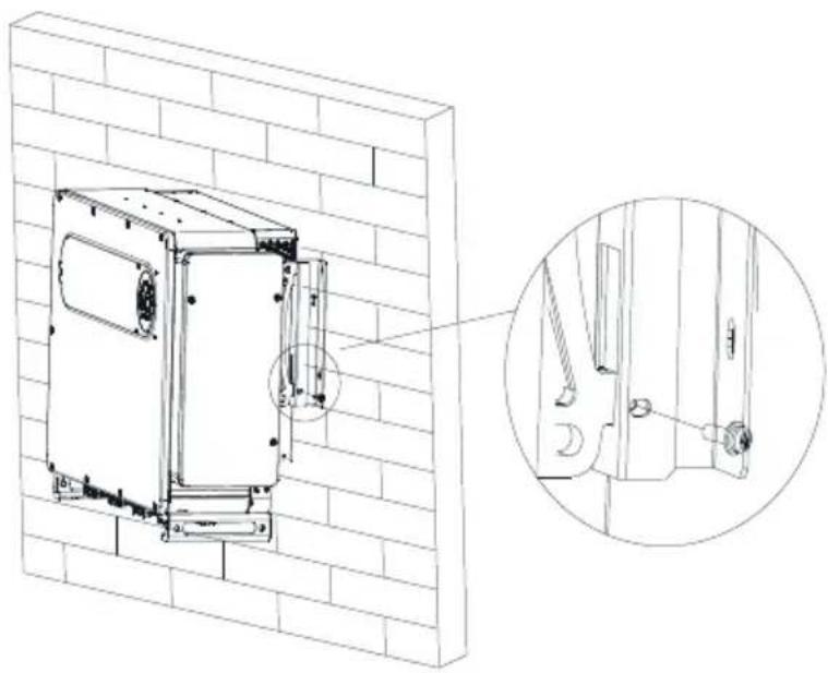
natural_image
Technical line drawing of a wall-mounted electrical enclosure with an inset close-up showing internal components (no text or symbols)Fig 5.14
6 Connecting Cable
Decisive Voltage Class (DVC) indicated for ports
| Port Name | Class |
| AC | C |
| DC | C |
| DRMS | A |
| RS485&USB | A |
6.1 Connection on AC side
 DANGER DANGER | · Before electrical connection, please ensure the inverter DC switch is at“OFF”, and disconnect AC switch, otherwise the high voltage from inverter may cause life risk.· Only trained authorized electrical technician can do the electric connection also please follow the connection procedures in this manual along with local country's regulations.· High voltage may cause electric shocks and serious injury please do not touch the inverter.· Please do not store inverter in area with flammable and explosive material. |
 WARNING WARNING | · Each inverter must install one AC breaker ,and one AC breaker is forbidden to share with other inverters.· It is forbidden to add load between inverter and breaker. |
Preparation before connection:
1> Disconnect inverter DC switch and AC breaker or switch.
2> When you lock the AC cable's screw, the torque force should be 25kgf·cm
When you lock the cover screw, the torque force should be 20kgf·cm.
3> Measure the grid voltage and frequency, please refer to chapter 10.
AC breaker specification:
| Inverter model | Breaker model |
| MAX 175KTL3-X HV | 200/250A 1000Vac |
| MAX 185KTL3-X HV | 200/250A 1000Vac |
| MAX 196KTL3-X HV | 200/250A 1000Vac |
| MAX 216KTL3-X HV | 200/250A 1000Vac |
| MAX 225KTL3-X HV | 250/320A 1000Vac |
| MAX 230KTL3-X HV | 250/320A 1000Vac |
| MAX 250KTL3-X HV | 250/320A 1000Vac |
| MAX 253KTL3-X HV | 250/320A 1000Vac |
Cable specification:
| Inverter Model | Copper wire cross sectional (mm2) | Copper wire recommendation (mm2) |
| MAX 175KTL3-X HV | 70-95 | 70 |
| MAX 185KTL3-X HV | ||
| MAX 196KTL3-X HV | ||
| MAX 216KTL3-X HV | ||
| MAX 225KTL3-X HV | ||
| MAX 230KTL3-X HV | ||
| MAX 250KTL3-X HV | ||
| MAX 253KTL3-X HV |
Notice: The cable must be unbroken. When using aluminum alloy cables, please use copper-aluminum transition terminals.
AC side connection steps:
 WARNING WARNING | • If the cable is thick, after tightening the cable do not shake it and ensure the cable is well-connected and then start the inverter. Loose connection may cause overheat. |
1>Following drawing shows inverter's AC terminal, R, S, T are three live lines
Notice: The screw is a matching M12 screw.
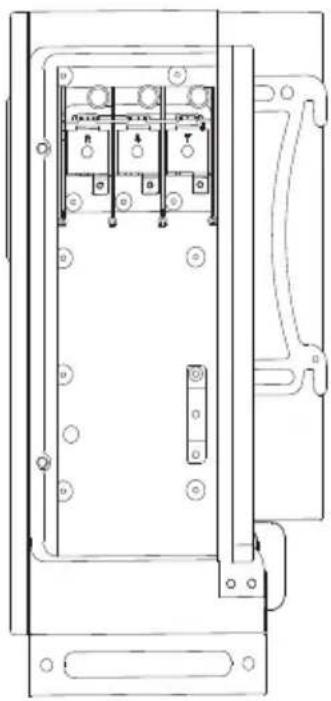
natural_image
Technical line drawing of an electrical enclosure with internal components and mounting points (no text or symbols)Fig 6.1
2>Open the AC junction box first, and then pass the cable through the waterproof silicone gasket. Determine the stripping length (approximately 30mm) according to the specifications of the crimping terminal. Use crimping tools to crimp the wires and terminals, then connect the cables to the corresponding channels through the waterproof interface, and tighten the screws.
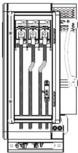
natural_image
Technical line drawing of an electrical cabinet or enclosure with internal components and wiring (no text or symbols)Fig 6.2
Diagram of how to install a terminal:
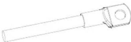
natural_image
Technical line drawing of a cylindrical mechanical component with a flanged end (no text or symbols)Fig 6.3
3> Upon completion of the AC wiring, remember to seal the water-proof silicone mat with the fireproof mud in order to ensure good waterproof performance.
 WARNING WARNING | The device damage caused by failure to seal the output terminal gaps as instructed is beyond the scope of warranty and Growatt New Energy shall not be liable for the damage. |

6.2 Connection On DC Side
DANGER
- Before electrical connection please ensure the inverter DC switch is at "OFF" also disconnect AC switch, otherwise the high voltage from inverter may cause life risk.
- Only trained authorized electrical technician can do the electric connection also please follow the connection procedures in this manual along with local country's regulations.
- High voltage may cause electric shocks and serious injury please do not touch the inverter.
- Do not place flammable or explosive materials around the inverter.
Notice: The sunlight will generate voltage on the solar panels, after serial connection, the high voltage may injure personnel, so before connect DC input cable you need cover solar panels with light-tight materials and make sure the inverter DC switch is at "OFF" status, otherwise high voltage may injure personnel.

WARNING
- Please ensure that the following conditions are met, as failure to do so may damage the inverter or pose a fire hazard. In such cases, the company shall not be liable for any consequences.
1>Each string's maximum open circuit voltage cannot exceed 1500Vdc, other-wise it could lead to fire or damage the inverter. If the inverter was damaged by higher maximum open circuit voltage (higher than 1500Vdc), product warranty will be forfeited and Growatt will not take any responsibility.
2>Each string solar panels should be same brand and same model. The inverter shall be used with IEC 61730 Class A rating PV module.
3>Under any circumstance, the maximum short circuit current should not exceed 50A.
4>The total panels power should not exceed 1.5 times of inverter input power.
5>To optimize system settings, recommend two strings with same amount solar panels.
6>Please use the positive and negative metal contacts and the DC connectors delivered with the inverter package. Using other incompatible models may result in severe consequences, which will void the warranty.
7>When assembling the DC connectors, pay attention to the correct polarity and label the positive and negative cables.
8>Crimp the PV metal contact with a dedicated crimper. Using an inappropriate crimping tool may lead to severe consequences, and any device damage caused by this is not covered by the warranty.
9>Cables with high rigidity are not recommended for the DC input as bending of cables may lead to poor contact of terminals.
10>According to the specification of the crimping terminal, determine the stripping length, crimp the wire and terminal with the crimping pliers, and connect them to the corresponding connector housings separately, and hear the click sound to ensure the connection is good. After snapping the positive and negative connectors into place, pull the cables slightly to ensure that they are securely in place.
11>Connectors need to be fit with male and female terminals, before connecting panels with inverter please make sure the positive pole and negative pole, namely the solar panels'positive pole connect to "+" negative pole connect to"-.
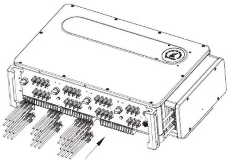
natural_image
Technical line drawing of an electronic device chassis with multiple ports and connectors (no text or symbols)Fig 6.5
12>For the unused PV terminls on the inverter, please cover them with blue dustproof caps.
13>When wiring the DC input cables at the installation site, leave at least 50 mm of them slack. The axial tension on the PV connector should not exceed 80N and do not apply radial stress or torque on the PV connectors.
14> Connect the positive and negative poles to inverter terminals, different inverter's maximum single string input current please refer to following table:
| Inverter model | Max. single string input current |
| MAX 175-253KTL3-X HV | 15A*2 |
15> Cable specifications:
| Inverter model | Cross-sectional area( mm^2 ) | Recommendation ( mm^2 ) | Cable outer diameter(mm) |
| MAX 175-253KTL3-X HV | 4-6 | 4 | 4.5-7.8 |
Notice:
-
Under any circumstance, the total current of all strings cannot exceed the inverter's maximum current
-
Do not touch any working solar panels.
-
Make sure the cable is unbroken.
6.3 Connection Of Communication Cables
6.3.1 RS485 port
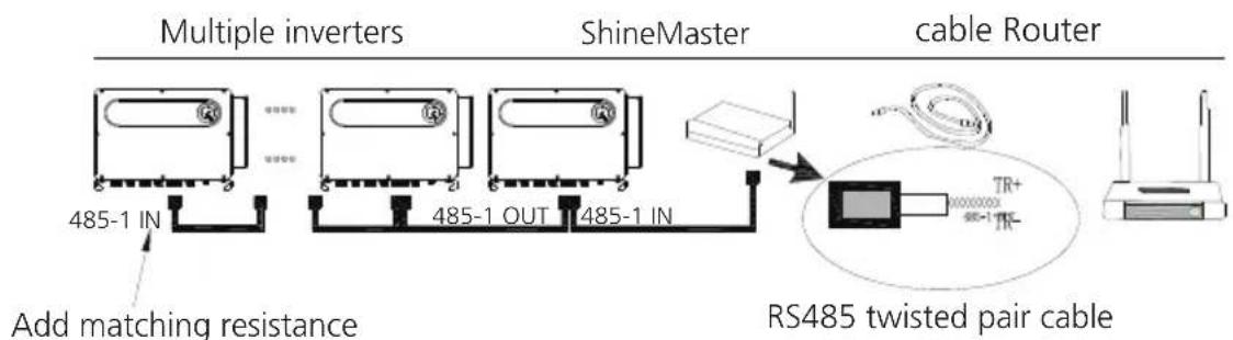
RS485 can carry out single-machine communication or multi-machine (32pcs) long-distance (500 meters) high-speed (baud rate 38400) communication. It is recommended to use twisted-pair shielded wire for RS485 communication line. For single-machine communication, the communication line can be connected to pin 3/4, and its shielding layer can be connected to pin 1. When multiple machines are connected in parallel, two RS485-1 ports can be connected at the same time. When used, the shielding layer can be connected to pin 1/2. In Figure 6.6, RS485 has two terminal types, terminal type 1 and terminal type 2.
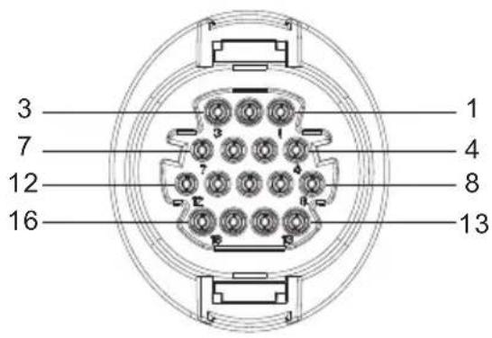
Terminal type 1
Terminal type 2
| Port | PIN | Description | Port | PIN | Description |
| Shield ground | 12 | 485-1 / 485-2 PE shield | DRMS | 9 | DRM1/5 |
| RS485-1 IN | 3 | 485-1 A1 | 10 | DRM2/6 | |
| 4 | 485-1 B1 | 11 | DRM3/7 | ||
| RS485-1 OUT | 5 | 485-1 A1 | 12 | DRM4/8 | |
| 6 | 485-1 B1 | 13 | REF/GEN | ||
| RS485-2 | 7 | 485-2 A1 | 14 | DRM0/COM | |
| 8 | 485-2 B1 | RS485-1Matching resistance | 15/16 | 485-1Matching resistance |
Notice:
- When multiple inverters communicate in parallel, the last machine needs to add matching resistance. The method is to use a wire to connect the pin 15/16 together.
- Terminal type 1 and terminal type 2 randomly match the whole machine shipment. The performance of the two terminals is consistent, only different in appearance. The client needs to match the corresponding shape terminal to use.
In MAX 175-253KTL3-X HV series inverters, RS485 interface is standard. The connection steps of RS485 communication line are as follows:
1) Unscrew the waterproof cover of the COM interface and remove it.
2) Connect the RS485 communication line to the port of 485-1.
3) The inverter is connected hand in hand through the RS485 communication line, and the end of the communication line 485_A/B is connected to the monitoring equipment to realize multi-machine remote monitoring.
Note: When locking the RS485 cable screw, the torque is 4kgf·cm.
natural_image
Technical line drawing of an electronic device chassis with internal components and a close-up of its internal structure (no text or symbols)Fig 6.7
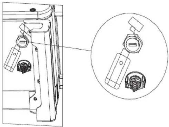
6.3.2 USB port
The MAX 175-253KTL3-X HV series inverters are equipped with a USB interface as standard, which can be connected to a USB to WIFI module, Shine GPRS-X2, Shine WIFI-X, Shine 4G-X, Shine Link-X and other optional monitoring modules to realize remote Monitoring function. In addition, you can also quickly upgrade the inverter software through the U disk:
Steps to install the monitoring module:
1> Loosen the waterproof cover of the USB interface and remove it.
2> As shown in Figure 6.8A, insert the Shine GPRS-X2 module into the USB interface, and the LED of the Shine GPRS-X2 module will be on.
3> As shown in Figure 6.8B, make sure that the is facing upwards, insert the monitoring module into the USB interface, and tighten the lock.
Note: If you use a USB to WIFI module, when the operator leaves, please take the module and the data cable away, and tighten the waterproof cover to prevent water from entering the interface.
natural_image
Technical line drawing of a mechanical component with an inset close-up showing internal components (no text or symbols)Fig 6.8A
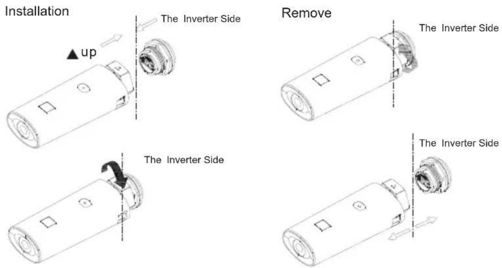
Fig 6.8B
6.4 Inverter demand response modes (DRMS)
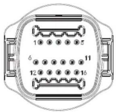
This series inverter has the function of demand response modes, We use 16-Pin socket as inverter DRMS connection.
 Information Information | DRMS application description➢ Applicable to Commission Regulation (EU) 2016/631.➢ DRM0, DRM5, DRM6, DRM7, DRM8 are available. |
| [CK2W]CAUTION | Damage to the inverter due to moisture and dust penetration➢ Make sure the cable gland has been tightened firmly.➢ If the cable gland are not mounted properly, the inverter can be destroyed due to moisture and dust penetration. All the warranty claim will be invalid. |
 WARNING WARNING | Excessive voltage can damage the inverter!External voltage of DRM PORT don't over +5V. |
6.4.1 Using the Power Control Interface for EU
DRM socket1

DRM socket2
Fig 6.9 Inverter – RRCR Connection
6.4.1.1 The following table describes the connector pin assignment and function:
| DRM Socket Pin NO. | Description | Connect to RRCR |
| 9 | Relay contact 1 input | K1 – Relay 1 output |
| 10 | Relay contact 2 input | K2 – Relay 2 output |
| 11 | Relay contact 3 input | K3 – Relay 3 output |
| 12 | Relay contact 4 input | K4 – Relay 4 output |
| 13 | GND | Relays common node |
| 14 | Not connected | Not connected |
6.4.1.2 The inverter is preconfigured to the following RRCR power levels:
| DRM Socket Pin 9 | DRM Socket Pin 10 | DRM Socket Pin 11 | DRM Socket Pin 12 | Active power | |
| Short circuit with Pin 13 | 0% | 1 | |||
| Short circuit with Pin 13 | 30% | 1 | |||
| Short circuit with Pin 13 | 60% | 1 | |||
| Short circuit with Pin 13 | 100% | 1 |
Active power control and reactive power control are enabled separately.
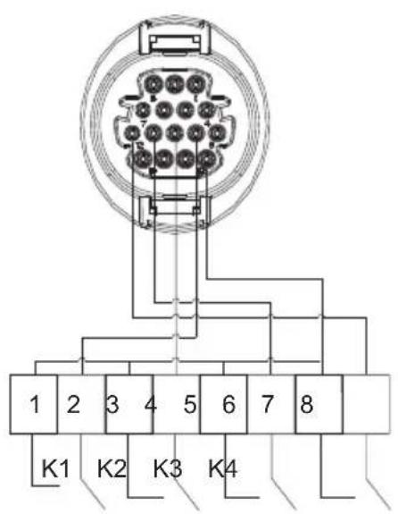
6.5 Connecting The Ground Cables
In this solar system all the unloaded metal components and cases should be connected to the ground. Single inverter need grounding over a PE point, multiple inverters need connect all the inverter PE cable and solar panels shelves to the same grounding point to achieve equipotential.
The grounding steps as following:
Take out the ground screw at the inverter bottom, connect the ground cables as following figure.
Notice: 1. The machine is safely separated from the lightning protection and the distance is as far as possible.
2.Do not expose Grounding terminal in the air and precaution for the rain.
3.When you lock the case ground screw, the torque force should be 60kgf·cm.
natural_image
Technical line drawing of a device with internal components and a close-up inset showing two circular components (no text or symbols)Fig 6.10
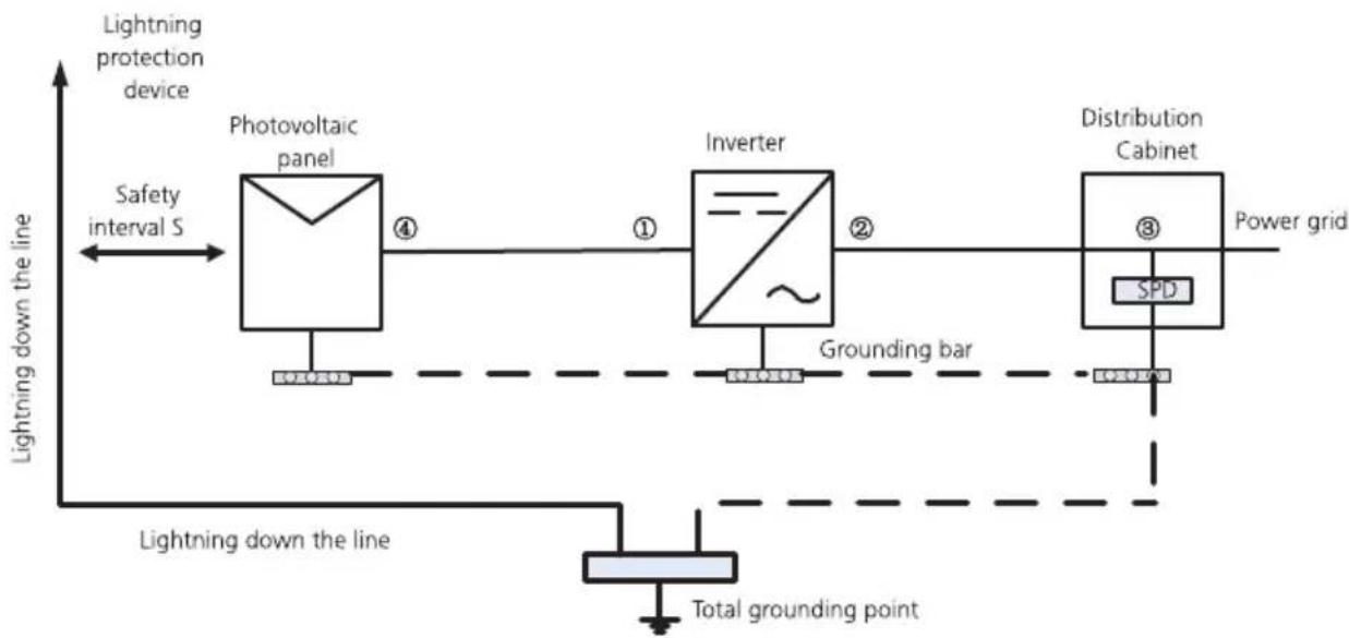
According to the relevant provisions of IEC 61643-32 "Connecting to photovoltaic devices surge protectors - selection and use of guidelines", whether for household or outdoor photovoltaic power plants, it is necessary to ensure the implementation of lightning protection measures for photovoltaic systems:
 WARNING WARNING | The lightning protection measures for photovoltaic systems shall be carried out in accordance with the corresponding national standards and IEC standards. Otherwise, photovoltaic devices such as components, inverters and power distribution facilities may be damaged by lightning.In this case, the company does not carry out warranty and assumes any responsibility. |
flowchart
graph LR
    A["Lightning protection device"] --> B["Photovoltaic panel"]
    B --> C["Inverter"]
    C --> D["Distribution Cabinet"]
    D --> E["Power grid"]
    F["Safety interval S"] --> B
    G["Grounding bar"] --> C
    H["Total grounding point"] --> I["Lightning down the line"]
Fig 6.11
1) It is generally recommended to install lightning protection devices (such as lightning rods / lightning protection belts and down conductors) to prevent lightning from hitting the PV array.
2) Lightning protection devices and down-conductors and related equipment in Suggested value of S: According to the general 5 storey height (about 15m) building roof, S takes 2.5m enough, this distance can be simplified according to the inverse relationship of the floor height.
A. When the safety distance S is satisfied:
The position ①③ of the figure should be equipped with a lightning protection module. In general, it is recommended to install Type II in position ① and Type I in position ③.
B. When the safety and safety distance S is not met:
In addition to position 3, Type I lightning protection module should be installed in Figure ①②④.
3) The lightning down conductor and the equipment ground wire eventually sink at a total ground point, but the two cannot share the wire. That is, the equipment grounding wire should be pulled separately, and the wire diameter requirement >6mm^2 when the safety interval distance S is satisfied.
4) About the above lightning protection lightning receptor system related design reference GB/T 21714.3-2015.
7.1 Commission The inverter

- If the inverter is stored over one month, its default time and date may looks wrong, the time and date should be reset before connection to the grid.
The inverter will be set to the appropriate model according to the standards of different countries or regions before leaving the factory. For example, the inverters shipped to Australia are configured as Australian model in the factory.
Note: The inverter is configured for Australia at the factory.
7.1.1 Set inverter address
After inverter is started normally, inverter address can be set via RS485/USB converting to WIFI. When multiple inverters are connected in parallel via RS485, the inverter must be set to a different communication address. When a single inverter communicates, the default communication address can be used.
Note: The default communication address of the inverter is 1, which can be set to 1-254.
7.1.1.1 Set RS485 address with Shinebus
The 485 address of the inverter can be modified by Shinebus, This operation is performed by a professional.
7.1.1.2 Set RS485 address on ShinePhone APP
Refer to 8.2 download mobile APP ShinePhone and connect to inverter WIFI to enter local monitoring page, this operation is performed by a professional.
1>Click "Parameters";
2>Enter password.(When you use it for the first time, you need to set the password first. Click "Reset password" to enter the OSS account number and password. The distributor and installer can apply for the OSS account from Growatt. Click "Sign in" to set the password. After the setting is successful, you can start using it.)
3>Click top item "COM Address";
4>Click the "Read" button in the upper right corner to read the current communication address of the inverter;
5> Set inverter com address;
6>Read inverter com address to ensure setting is successful;
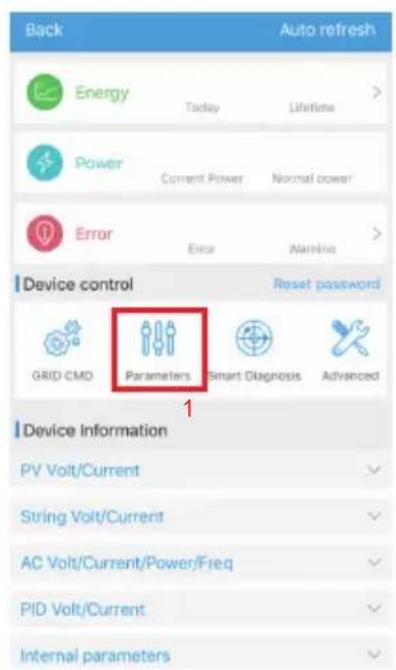
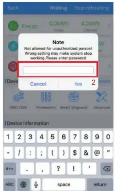
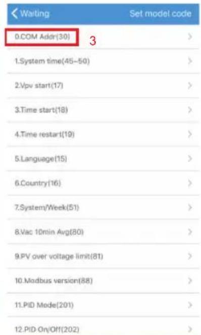
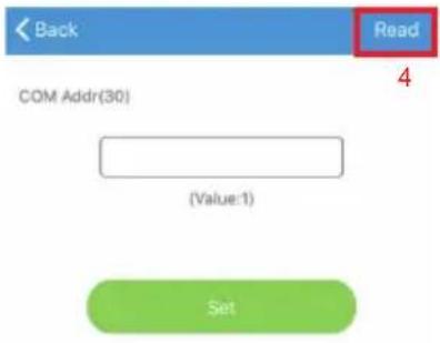
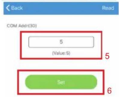


Fig 7.1
7.1.2 Set inverter time and date
Please refer to section 8.2.1 and login ShinePhone APP.Click "system time(45-50)" to set inverter time and date on the parameter setting page.
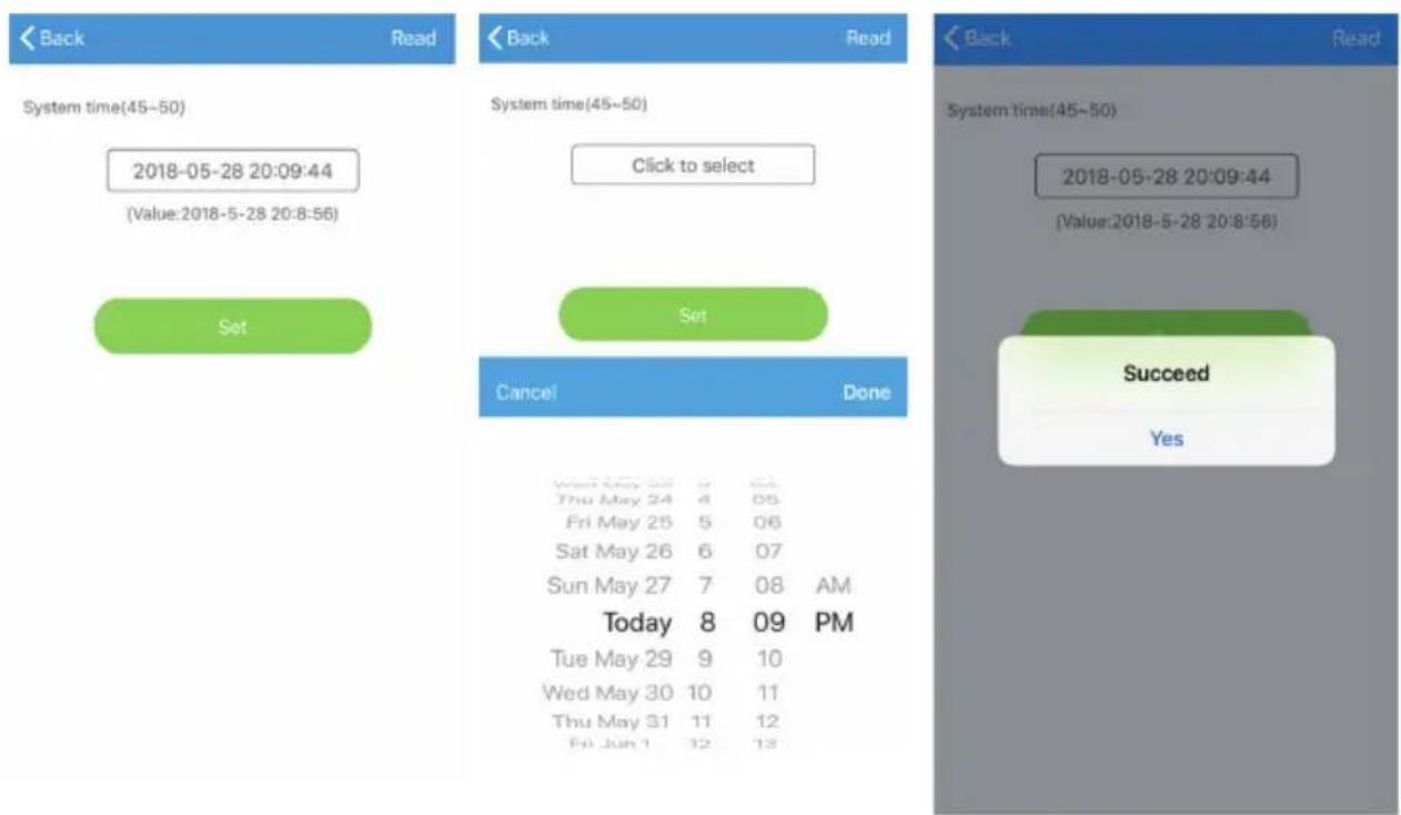
Fig 7.2
7.2 Operation Mode
7.2.1 Waiting mode
When the DC voltage is more than 500Vdc, inverter will be powered on and enters the "waiting" state.
At this mode, inverter will check the system parameter. If the system is normal and PV voltage is more than 500Vdc, inverter will try to connect to the grid.
7.2.2 Working mode
At this mode, inverter work normally, and the Power or fault code indicator light shows the power delivered by the inverter to the grid.
When the DC voltage is more than 500Vdc, inverter converts the DC power generated by the PV modules into AC power and supplies them to the grid.
When the DC voltage is lower than 500Vdc, inverter will enter into "waiting" state and try to connect to the grid, at this status, inverter consume very small power to check the internal system status.
Note: only when the PV modules supply enough power(voltage☐ 500Vdc) then the inverter will start automatically.
7.2.3 Fault mode
Inverter intelligent control system will continuously monitor and adjust system status. When there is a fault detected, LED will show the fault message.
Note: Please refer to section 9.2 to check the fault message and take corrective measures.
7.2.4 Off mode
When the sunlight is weak or no light, inverter will stop working automatically. When it is off, inverter will not consume gird power or PV module. At the same time, the LED of inverter will be turned off.
Note: When PV string DC voltage is too low(≤500Vdc), inverter will be off.
7.3 LED Display
Inverter current operation status can be visually checked from LED display directly.
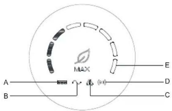
Fig 7.3
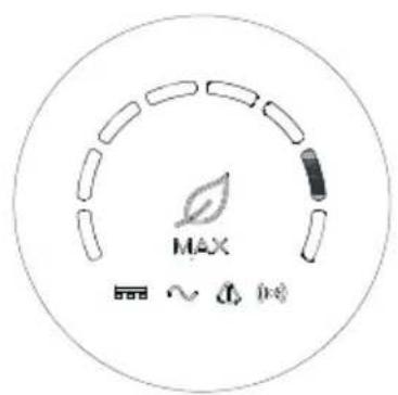
Fig 7.4
| Description of LED status | |||
| Position of LED | Type of LED | Inverter status | LED status |
| A | PV voltage indicator light | PV voltage reaches grid voltage | Green light is on |
| PV voltage does not reach the grid voltage | Light is not on | ||
| B | AC voltage indicator light | Inverter is in the grid state | Green light is on |
| No AC voltage | Light is not on | ||
| With AC voltage, inverter is in the grid countdown state | The green light flashes slowly, and the alarm or fault indicator light is not on | ||
| B | AC voltage indicator light | With AC voltage, inverter is in the grid countdown state | The green light flashes slowly, and the alarm or fault indicator light is not on. |
| C | Alarm or fault indicator light | Inverter works normally | Light is not on |
| Inverter is in alarm state | Red light flashes slowly | ||
| Inverter is in fault state | Red light is on | ||
| D | Communication indicator light | nverter has external communication, such as RS485, GPRS, etc. | Green light is on |
| Inverter has no external communication | Light is not on | ||
| Inverter upgrade or USB interface is reading and writing data | Green light flashes | ||
| E | Power or fault code indicator lightLED | Inverter is in the grid state | The eight LEDs from left to right represent the power of the inverter: if 8 green lights are on, it represents 100% of the inverter power. As shown in Figure 7-3, it represents 37.5% of the inverter power, and so on. |
| Inverter is in fault state | The 8 LED lights from right to left represent the fault codes currently reported by the inverter. From right to left, they represent 1, 2, 4, 8, 16, 32, 64, and 128. For example, the first and fourth green LEDs on the right are always on, which means 1+8=9. In addition, add 200 to get 209, which means the inverter reports fault 209, and so on. | ||
Note: For related fault codes, please refer to 9.2 Trouble shooting
8 Monitoring
8.1 Remote Data Monitoring
MAX 175-253KTL3-X HV series inverter remote monitoring ways include APP(ShinePhone) and server Web page, RS485,GPRS,4G,PLC(reserved) can satisfy both ways of monitoring.
8.1.1 Mobile phone APP(ShinePhone) remote monitoring
1>Scan the following QR code, or download from Android store or App store by "searchingShinephone", download and install software.

Fig 8.1
Note: 1. Make you it's the latest version.
- Please find more details on http://server.growatt.com.
2> Users can register their mobile APP account by following the steps below: Run ShinePhone go to login page click register".Registration is required to fill in the information, with the * is required, the agreement is mandatory, you can log in to the main interface of ShinePhone after registration, the registration page and the main interface are as shown below.
Shinephone login and main page:

Fig 8.2
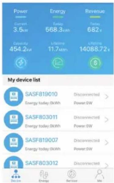
Fig 8.3
Device page:
1> Main page top middle is the name of current plant, user can click the "v" button to switch to other plants under this account.
2> User can add datalogger, check datalogger and add plant by click " + " button at the top right corner.
3> Top half shows current plant power, revenue today and total production.
4> My device list shows current plant device, user can see more details by click the device, left cross the device to stick the device and edit, edit operation includes change device alias, icon and delete device.

Fig 8.4 add datalogger
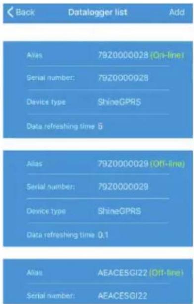
Fig 8.5 datalogger list

Fig 8.6 add plant
Datalogger:
1> User can add more datalogger under the particular plant.
Way: Click "+" in the upper right corner of the device page and select "Add Collector (WiFi/GPRS, etc.)", as shown in Figure 8.7.
Note: You can choose to manually enter the collector serial number for addition, or you can add it by scanning the barcode on the nameplate.
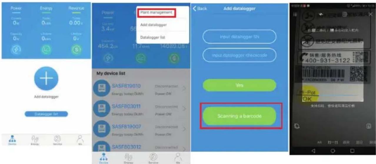
Fig 8.7
2> User can add datalogger at the datalogger list page to add a datalogger, edit, delete, configure etc.
3> User can add more plants with the add Plant function.
Device page and function:
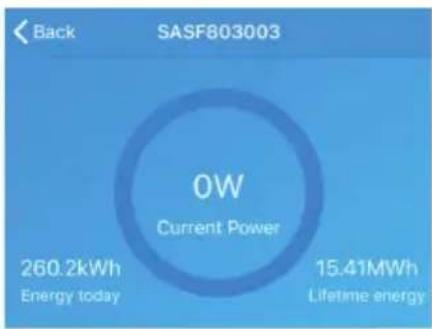
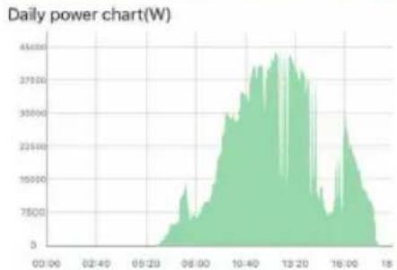
1> Device page: User can click the device to see more details, the device page show current power and Energy today and daily power chart, user can find more with control, parameter, data and Events page.
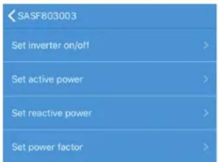
2> Control: user set inverter on/off, set active power, set reactive power, set PF, set inverter time, set grid voltage high, set grid voltage low. The operation password is : inverter+date, for example inverter20170722.
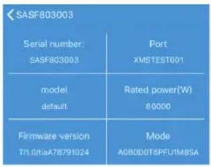
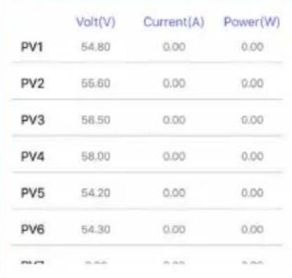
3>Parameter: user can see device SN, rated power, firmware version, PV1 voltage, current, and power etc.
line
| Time | Power Chart (W) | | ------ | --------------- | | 00:00 | 0 | | 02:40 | 0 | | 05:20 | 0 | | 06:00 | 7500 | | 06:30 | 15000 | | 07:00 | 22500 | | 07:30 | 30000 | | 08:00 | 37500 | | 08:30 | 45000 | | 13:20 | 45000 | | 16:00 | 37500 | | 18:00 | 7500 |
Control

Parameters

Data

Events
Fig 8.8
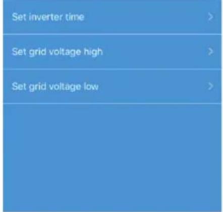
Fig 8.9
other
| Device | Volt(V) | Current(A) | Power(W) | |---|---|---|---| | PV1 | 54.80 | 0.00 | 0.00 | | PV2 | 55.60 | 0.00 | 0.00 | | PV3 | 58.50 | 0.00 | 0.00 | | PV4 | 58.00 | 0.00 | 0.00 | | PV5 | 54.20 | 0.00 | 0.00 | | PV6 | 54.30 | 0.00 | 0.00 | | PV7 | 5.50 | 0.00 | 0.00 |Fig 8.10
4> Data page: user can see the PV power, voltage, current, R phase power, S phase power, S phase power, T phase power, output power by day, month, year, by finger up cross the screen.
5> Events: User can see the fault message if there it is.
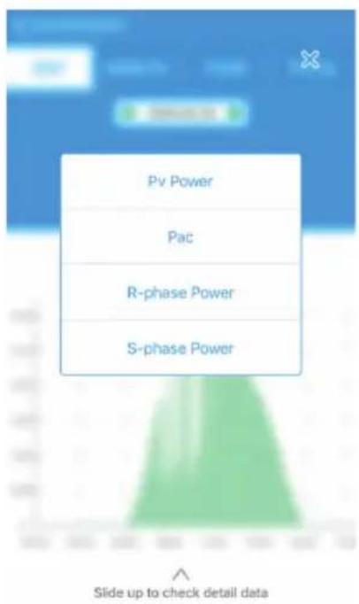
Fig 8.11
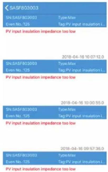
Fig 8.12
8.1.2 GPRS /4G
8.1.2.1 Register account
1> Register account
Open browser, input "server.growatt.com", click "New User" at login page, input the necessary information then go back to login page, input the registered username and password, click "Sign In".
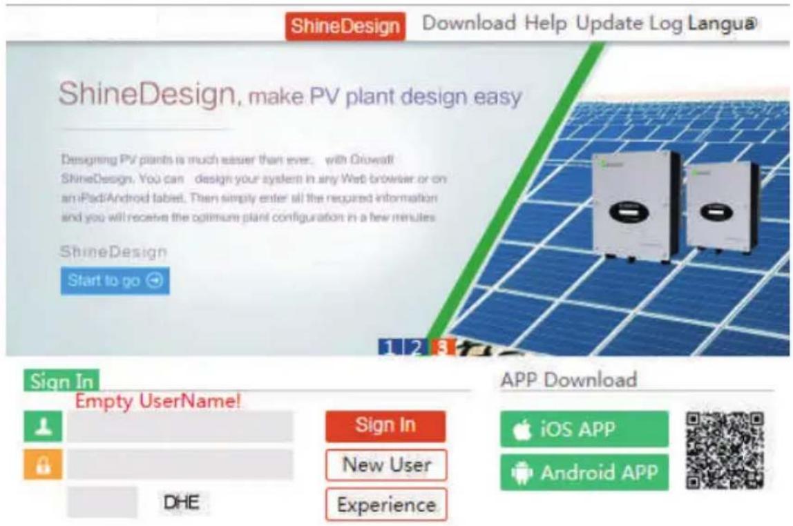
Fig 8.13
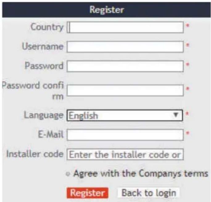
Fig 8.14
2> Add datalogger
At Plant page, click device manage, then click add datalogger, input the SN and valid code then save, after device is powered on, datalogger will show after 5mins, also the device will come online(our device is monitored by datalogger, so need to add the datalogger here first).
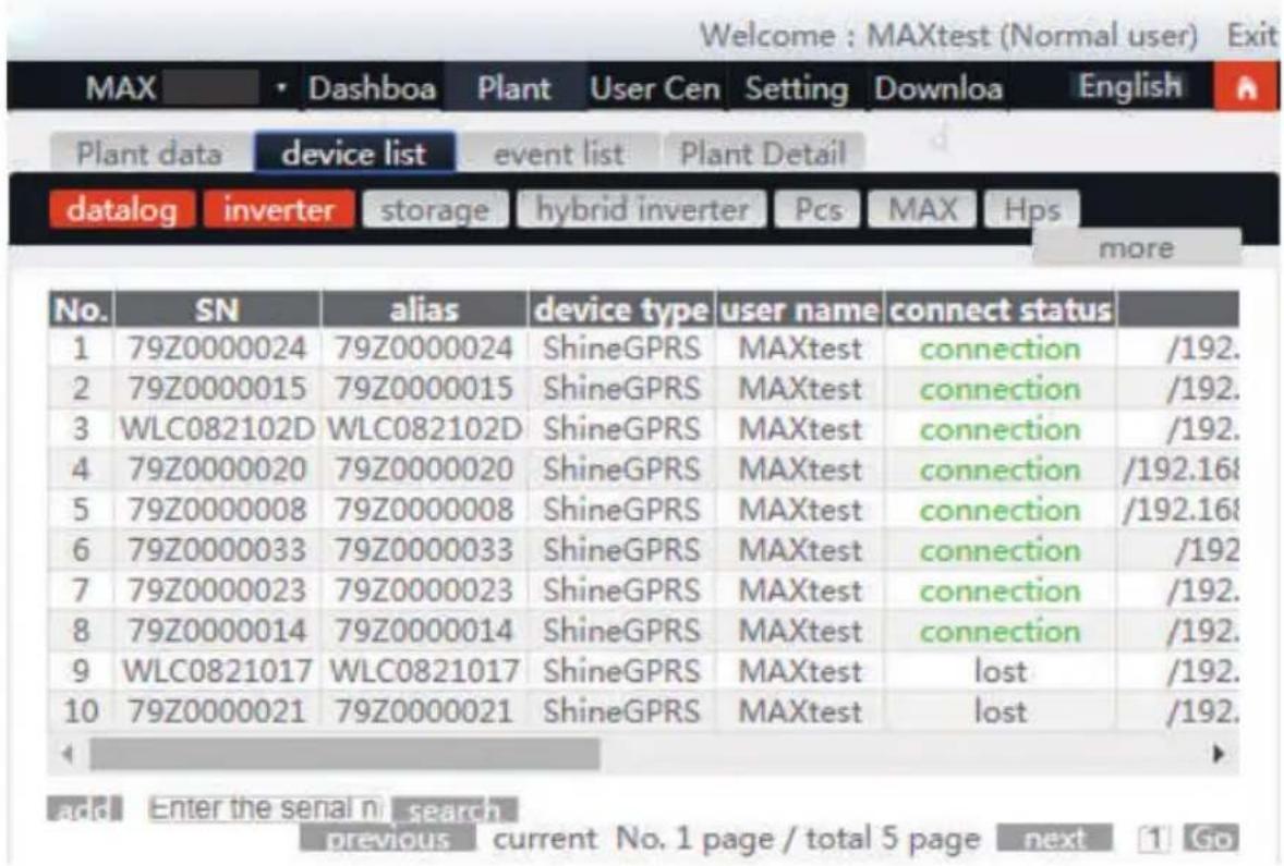
Fig 8.15
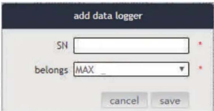
Fig 8.16
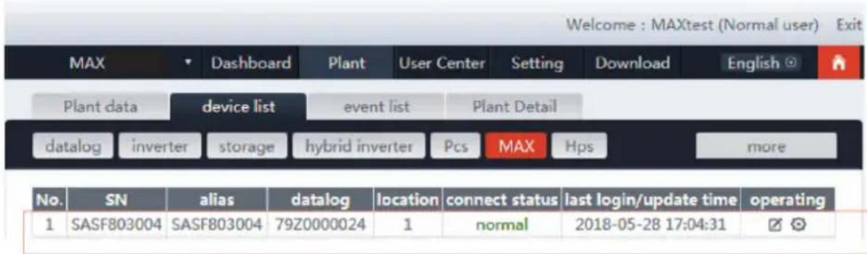
Fig 8.17
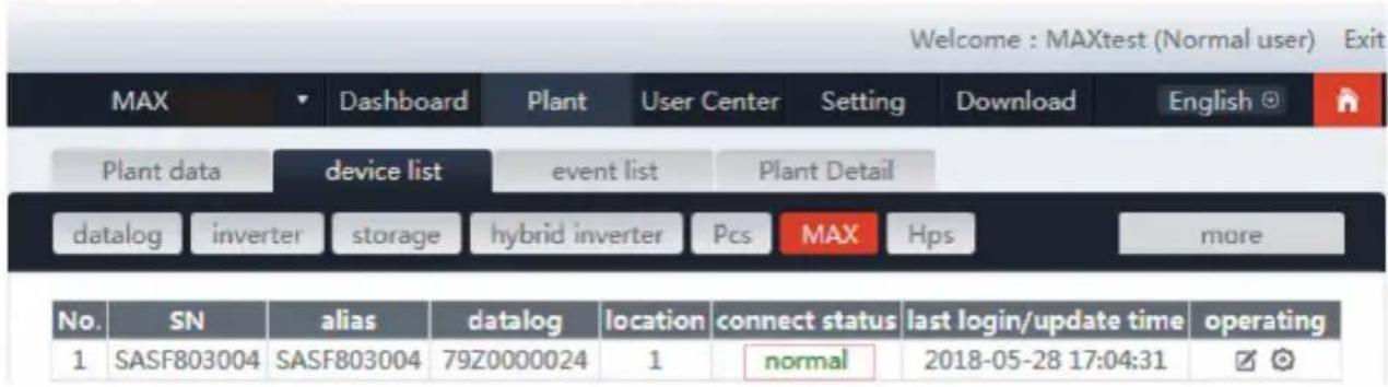
Fig 8.18
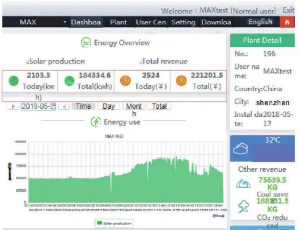
3> Data reading
A. Basic production reading, Energy today, total production, revenue today and accumulative revenue are showing on this page.
line
| Time (h) | Solar Production (kW) | | -------- | --------------------- | | 00:00:00 | 80000 | | 01:00:00 | 80000 | | 02:00:00 | 80000 | | 03:00:00 | 80000 | | 04:00:00 | 80000 | | 05:00:00 | 80000 | | 06:00:00 | 80000 | | 07:00:00 | 80000 | | 08:00:00 | 80000 | | 09:00:00 | 80000 | | 10:00:00 | 80000 | | 11:00:00 | 80000 | | 12:00:00 | 80000 | | 13:00:00 | 80000 | | 14:00:00 | 80000 | | 15:00:00 | 80000 | | 16:00:00 | 80000 | | 17:00:00 | 80000 | | 18:00:00 | 80000 | | 19:00:00 | 80000 | | 20:00:00 | 80000 | | 21:00:00 | 80000 | | 22:01:54 | 8524 | | 23:54:54 | 8524 | | 24:54:54 | 8524 | | 25:54:54 | 8524 | | 26:54:54 | 8524 | | 27:54:54 | 8524 | | 28:54:54 | 8524 | | 29:54:54 | 8524 | | 31:54:54 | 8524 | | 32:54:54 | 8524 |Fig 8.19
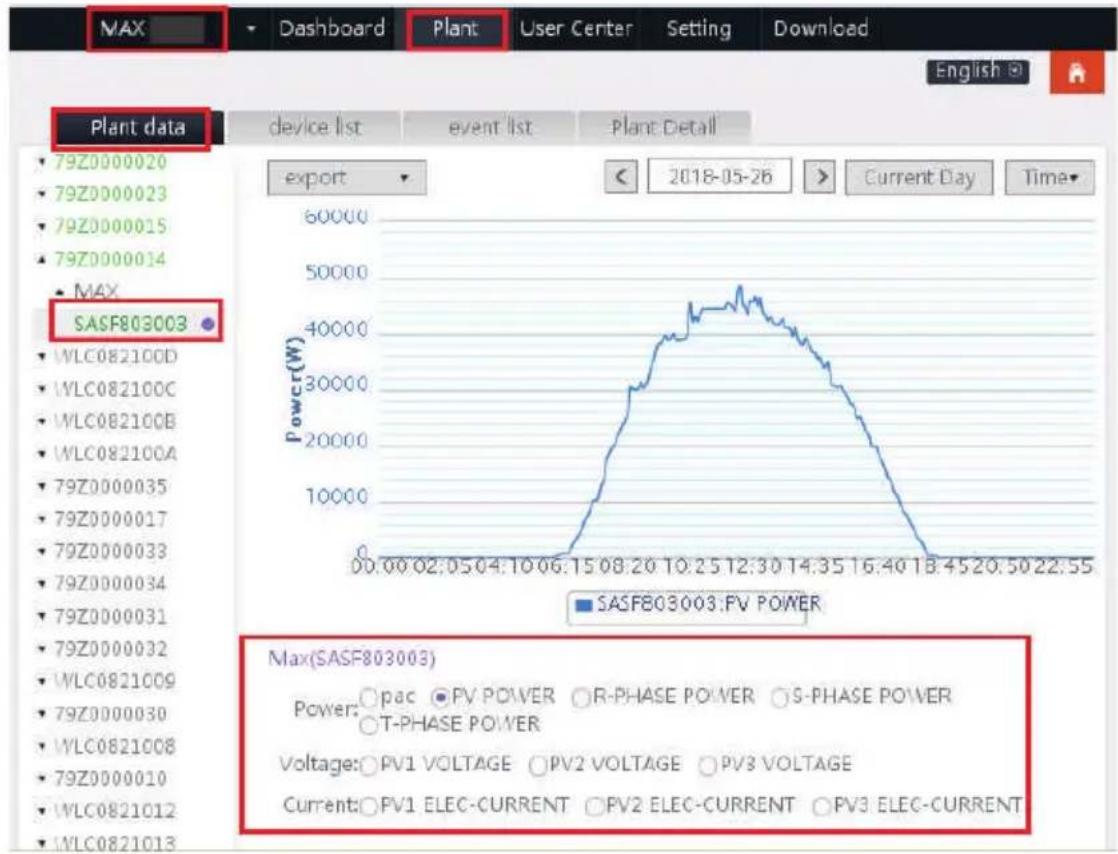
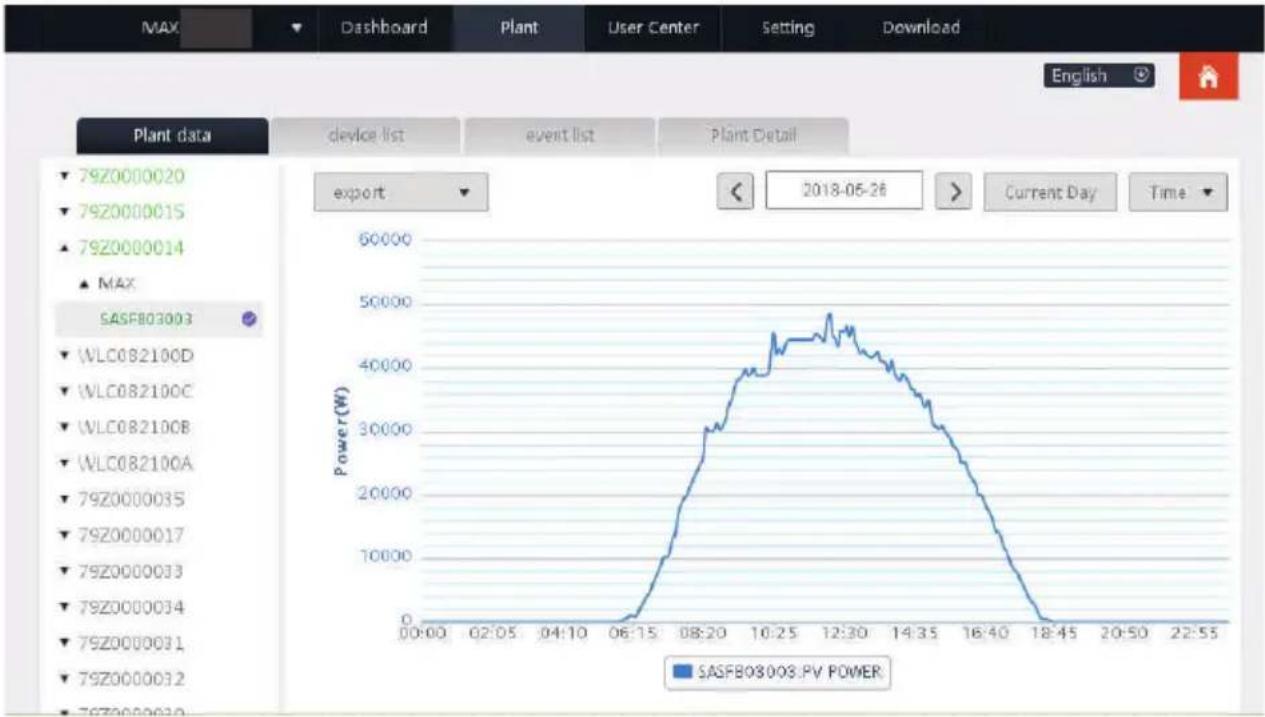
B. Plant data page can check device power, voltage curve by time, day, month or year.
line
| Time | Max(SASF803003) | | ---------- | --------------- | | 00:00:02:05 | 0 | | 04:10:06:15 | 0 | | 08:20:10:25 | 45000 | | 12:30:14:35 | 45000 | | 16:40:18:45 | 45000 | | 20:50:22:55 | 45000 |Fig 8.20
4>Set up the equipment
The device management page selects MAX. The serial number of the device to be set can be found in the list.
Notice: The following operations are requested by professionals.
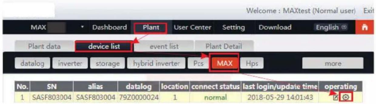
Fig 8.21
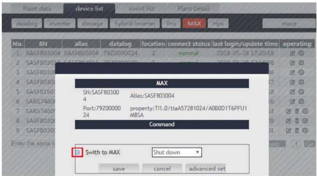
Fig 8.22
5>Check detailed data
Double-click the device serial number in the device list. The detailed data page is displayed. Data pages can be viewed by date or exported.
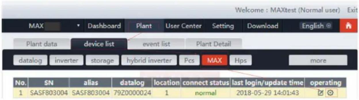
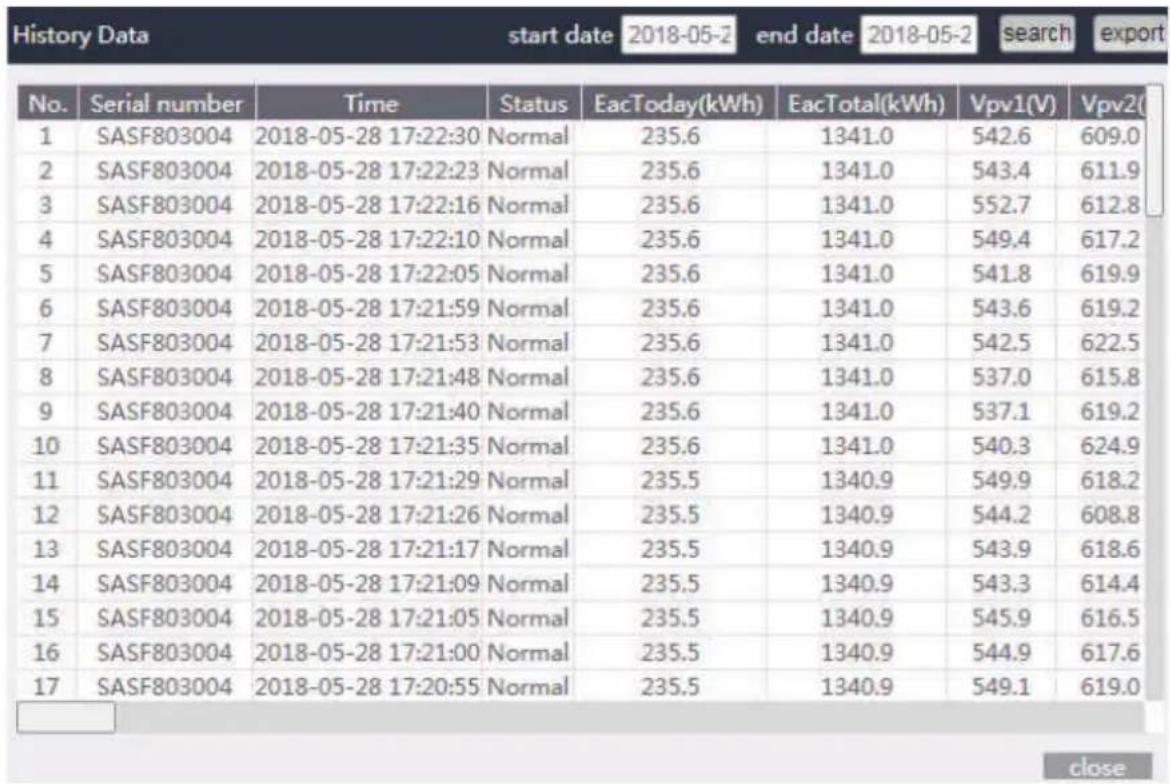
Fig 8.24
8.1.2.2 Shinemaster monitoring
This is a cost-effective and compact monitoring device that is specially designed for solar power plants, with a high-speed CPU and a stable Linux system that intelligently records the user's system characteristics.
flowchart
graph LR
    A["Multiple inverters"] --> B["485-1 IN"]
    B --> C["Add matching resistance"]
    D["ShineMaster"] --> E["485-1 OUT"]
    E --> F["485-1 IN"]
    F --> G["RS485 twisted pair cable"]
    G --> H["cable Router"]
    H --> I["TR+ 00000000 TR-"]
Feature:
1> A versatile and high-performance communication data logger that notifies the user of system status at any time.
2> Flexible parameter setting, system information management, error prompting and recording, high-capacity storage.
3> Collect data and upload data to Growatt in real time over the network.
Note: The smart meter and environmental monitor must be Growatt's designated manufacturer, otherwise monitoring will not be possible. When RS485 of multiple machines is used in parallel, please connect the ground wire according to section 6.3.1.
Fig 8.23
The system framework of communication monitoring is shown in the figure below. Users can choose the most suitable monitoring method according to the actual situation.
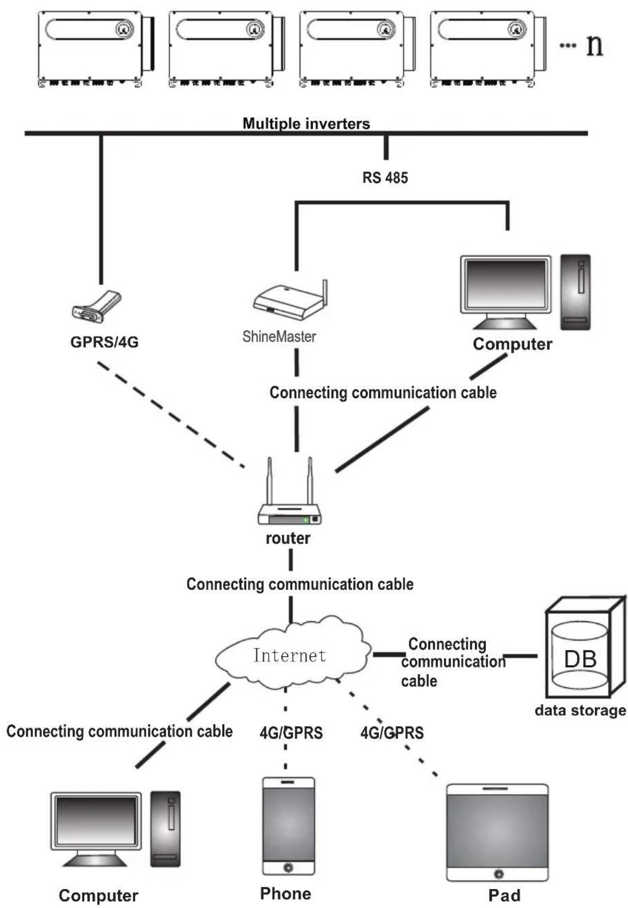
flowchart
graph TD
    A["Multiple inverters"] --> B["GPRS/4G"]
    A --> C["ShineMaster"]
    A --> D["Computer"]
    C --> E["Connecting communication cable"]
    D --> E
    E --> F["router"]
    F --> G["Connecting communication cable"]
    G --> H["Internet"]
    H --> I["4G/GPRS"]
    H --> J["4G/GPRS"]
    H --> K["DB data storage"]
    H --> L["Computer"]
    H --> M["Phone"]
    H --> N["Pad"]
    style A fill:#f9f,stroke:#333
    style B fill:#ccf,stroke:#333
    style C fill:#ccf,stroke:#333
    style D fill:#ccf,stroke:#333
    style E fill:#cfc,stroke:#333
    style F fill:#fcc,stroke:#333
    style G fill:#cff,stroke:#333
    style H fill:#ffc,stroke:#333
    style I fill:#cfc,stroke:#333
    style J fill:#cfc,stroke:#333
    style K fill:#cfc,stroke:#333
    style L fill:#cfc,stroke:#333
    style M fill:#cfc,stroke:#333
1>ShineMaster IP Address query
A. The PC and shinemaster lan ports are connected to the router's port through the network cable, so that they are in the same local area network.
B. Go to the router's management page and check the "Internet host list" to query the IP address of the ShineMaster serial number as the name of the connected device. This IP is the IP address assigned by the router to the ShineMaster. If you do not know how to do this, contact your network administrator for operation.
Note: The router needs to enable automatic IP assignment, that is, open the DHCP function.
C. Enter the shinemaster IP address in the browser to enter the shinemaster built-in page.
2>ShineMaster Built-in page access
Before accessing, check whether the communication cable between the devices is securely connected. After the check is correct, you can enter the ShineMaster IP address in the IE browser to access the built-in page of the ShineMaster. As long as the
ShineMaster is on the same network segment as the computer you are accessing, you can access the ShineMaster built-in server.
A. If the user successfully visits the shinemaster built-in page, they can go directly to the built-in page login interface, as shown in figure 8.25 below.
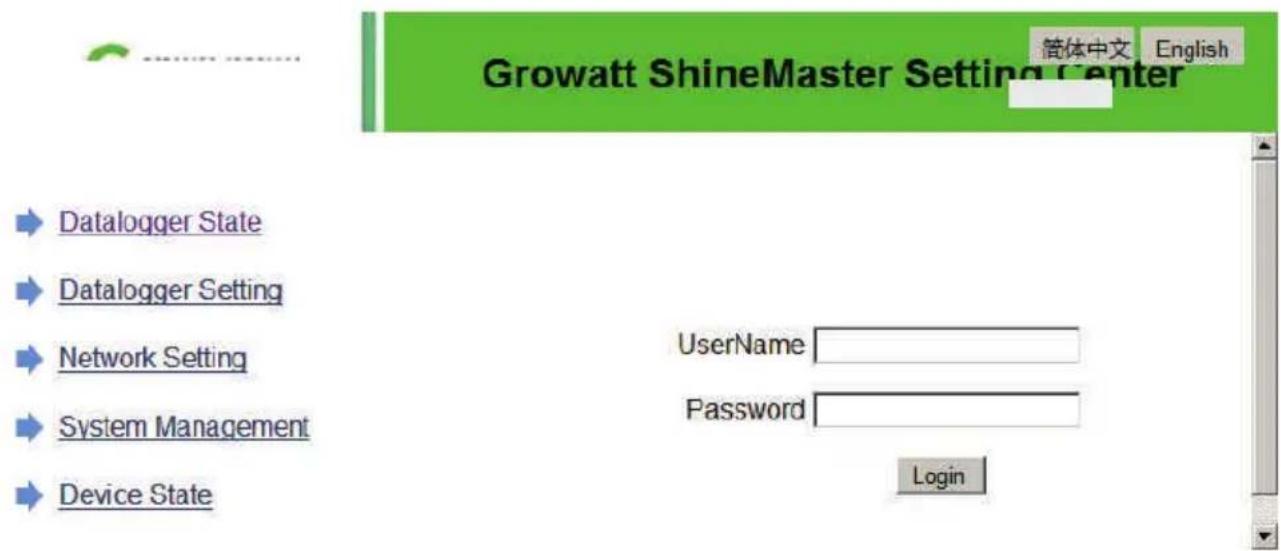
Fig 8.25
B. Enter user name and password, default login username: admin password: admin. click login after filling in, enter growatt shinemaster system page.
3>ShineMaster Data collector status view
Click on the status of the shinemaster data collector to view shinemaster "system state information", "serial number," server address, "number of connected devices," and so on.
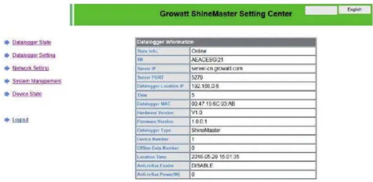
Fig 8.26
4>ShineMaster Data collector add or delete device
ShineMaster Before monitoring photovoltaic devices, we need to enter the page of the built-in shinemaster data collector settings to add devices.
A. Add device
1) Select the monitoring mode for monitoring photovoltaic devices in the first drop-down list of add or remove devices.
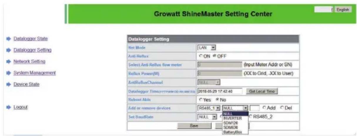
Fig 8.27
2) Select the type of photovoltaic device monitored in the second drop-down list.
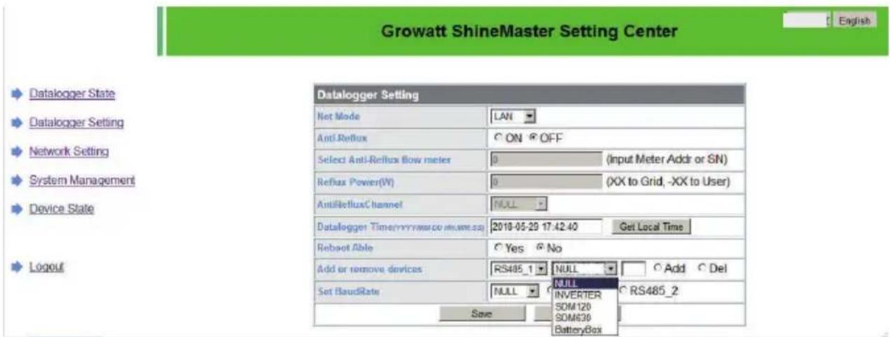
Fig 8.28
3) Fill in the third drop-down list with the photovoltaic device correspondence address.
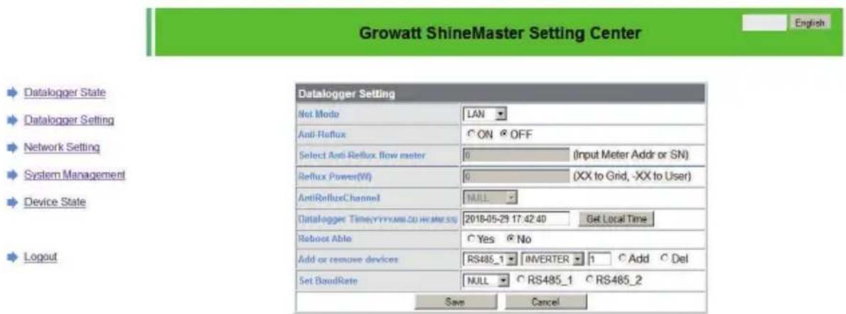
Fig 8.29
4) Select "Add" and then click "Save".
5) Go to the device status page after saving success to confirm that the device was added successfully.
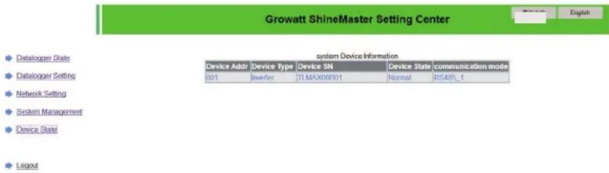
Fig 8.30
B. Delete device
1) Select the first drop-down list of "add or remove devices" to monitor the monitoring mode of photovoltaic devices.
2) Select the type of photovoltaic device monitored in the second drop-down list.
3)Fill in the third drop-down list with the photovoltaic device correspondenc address..
4) Select the following "del" and click Save to complete the device addition.
5) Enter the device status page after successful save to confirm that the device was deleted successfully.
5>ShineMaster Data upload to ShineServer
A. Register、Login
1) Enter the server domain name in the computer browser to enter the shineserver login page, if you are logged in for the first time, please register the user name. Enter the domain name access page, as shown in figure 8.32 below.
Chinese user server domain name: http://server-cn.growatt.com.
The domain name of the international user server i: http://server.growatt.com.
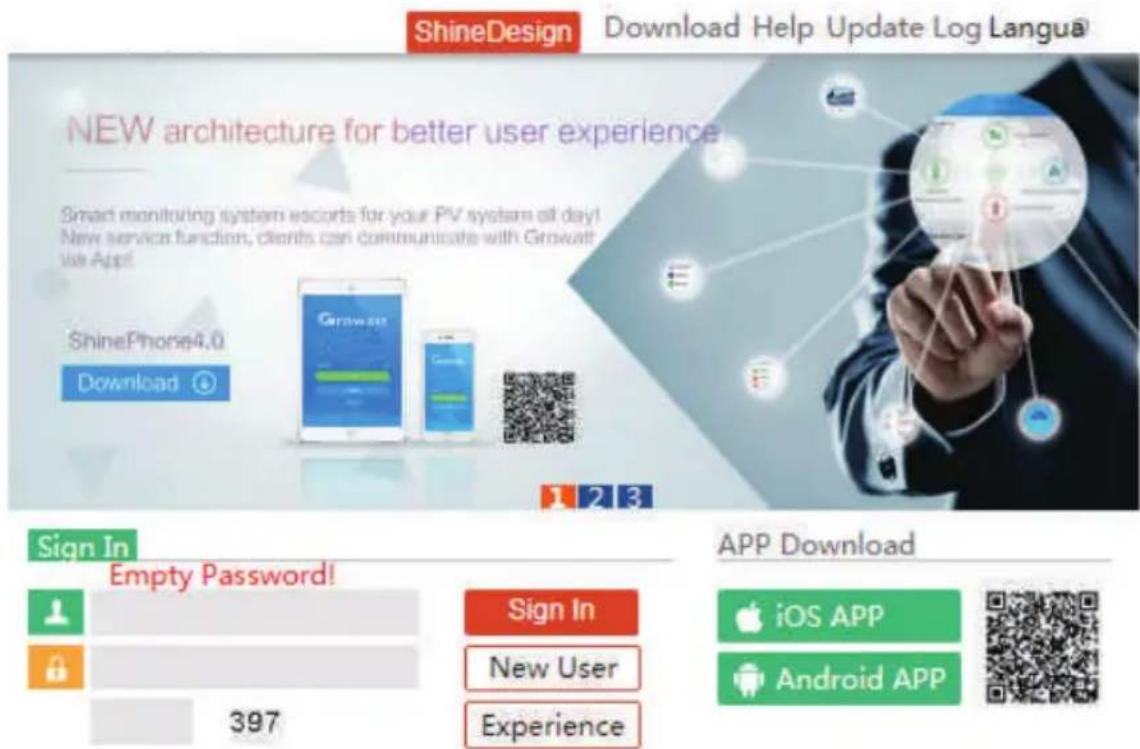
Fig 8.31
2) Register user name, input user information according to prompt, after information is completed, click "register".
Note: "collector serial number" and "collector check code" see shinemaster serialnumber box or guarantee box.

Fig 8.32
B. View monitoring data
1) After registration is complete, jump to the shineserver main interface automatically. Click on "power station" and "work information" to display the information for the power station's total power flow chart on the same day. The drop-down list "Select collector" allows you to view the daily power flow chart of a single inverter for the power station.
line
| Time | Power (W) | | -------- | --------- | | 00:00 | 0 | | 02:05 | 0 | | 04:10 | 0 | | 06:15 | 0 | | 08:20 | 30000 | | 10:25 | 45000 | | 12:30 | 48000 | | 14:35 | 40000 | | 16:40 | 25000 | | 18:45 | 5000 | | 20:50 | 0 | | 22:55 | 0 |Fig 8.33
2) By clicking on "power station" and "equipment management" in turn, the real-time data of "data collector", "inverter", "environment monitor", "intelligent meter" and "confluence box" MAX "can be viewed.
8.2 Local Data Monitoring
MAX 175-253KTL3-X HV series Inverter local data monitoring mode has a mobile phone app phone) and PC direct connection, udisk, details are as follows.
8.2.1 Mobile phone app (Shinephone) Local Monitoring
8.2.1.1 Log on to app for local monitoring
Method 1
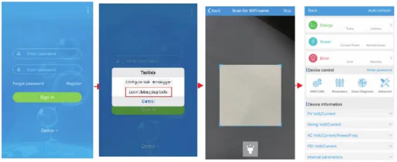
When you open the app login front page, click the top right corner toolbox icon. Pop up the toolbox, click the local debugging tool, and you can get the wifi name of the collector by scanning the QR code or barcode(The default password for WIFI is 12345678. If you have already connected, you can click "Skip" to connect directly to the WIFI.)
flowchart
graph LR
    A["Enter hostname"] --> B["Register"]
    C["Enter password"] --> B
    D["Forgot password"] --> B
    E["Sign in"] --> B
    F["Demo"] --> B
    B --> G["Toolbar<br>Configure WiFi debugging<br>Local debugging tools"]
    G --> H["Cancel"]
    H --> I["Sign in"]
    I --> J["Back Scan for WiFi name Skip"]
    J --> K["Device control Reset password"]
    K --> L["Auto refresh"]
    L --> M["Energy Tools Lifetime"]
    M --> N["Power Current Power Normal power"]
    N --> O["Error Error Warning"]
    O --> P["Device Information PV Volt/Current"]
    P --> Q["String Volt/Current"]
    Q --> R["AC Volt/Current/Power/Freq"]
    R --> S["PID Volt/Current"]
    S --> T["Internal parameters"]
Fig 8.34
Method 2
Open app enter user name and password click login, enter me (personal center). Click the enter tool, find the local debugger to enter, and you can get the wifi name of the collector by scanning the QR code or barcode (The default password for WIFI is 12345678. If you have already connected, you can click "Skip" to connect directly to the WIFI.)

flowchart
graph TD
    A["Enter username"] --> B["Enter password"]
    B --> C["Forgot password"]
    C --> D["Register"]
    D --> E["Sign in"]
    E --> F["Add datalogger"]
    F --> G["Datalogger list"]
    G --> H["Back Scan for WiFi name Skip"]
    H --> I["Device control"]
    I --> J["Auto refresh"]
    J --> K["Device Information"]
Fig 8.35
8.2.1.2 Use of local monitoring and debugging
When viewing local monitoring, you must keep the phone's wifi connected to the collector's wifi to view local monitoring (to enter the local monitoring page, first click auto refresh to get the latest data information).
Electricity generation: the option to view the latest generation, daily generation, monthly and annual generation of detailed information;
Power: you can see the current power and rated power value; failure: can read the equipment detailed fault information.
1>device control
Note: In addition to resetting the password to connect to the network, other WIFI modules that must connect to the collector can view information.
A. Reset password
Need network connection login oss account to set up or modify the local debug password.
B. Setting configuration
The configuration data of inverter, voltage, power and so on can be modified according to the usage (Fig 8.36).
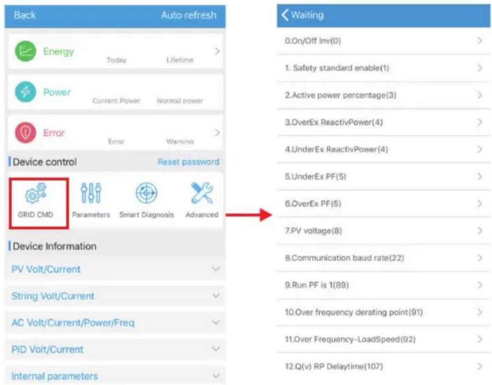
Fig 8.36
C.Parameter configuration
The parameter data of the equipment can be modified according to the usage (Fig 8.37).
D. Intelligent detection
Detailed and accurate view of the device's detailed data and status (Fig 8.38).
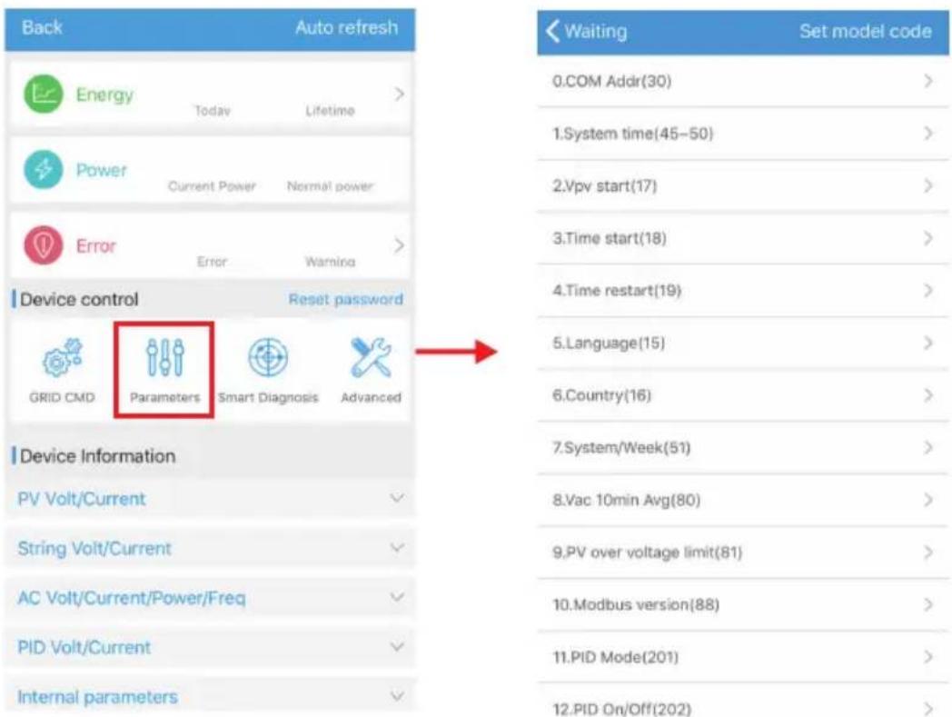
Fig 8.37
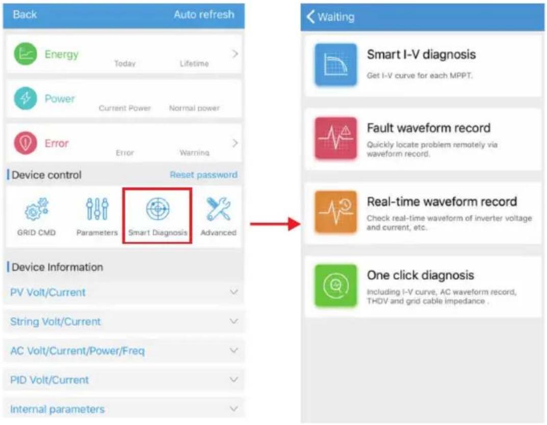
Fig 8.38
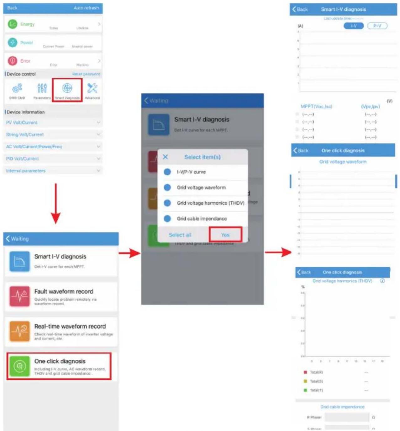
E. Intelligent I-V curve scanning Can remotely scan each mppt (Fig 8.39).
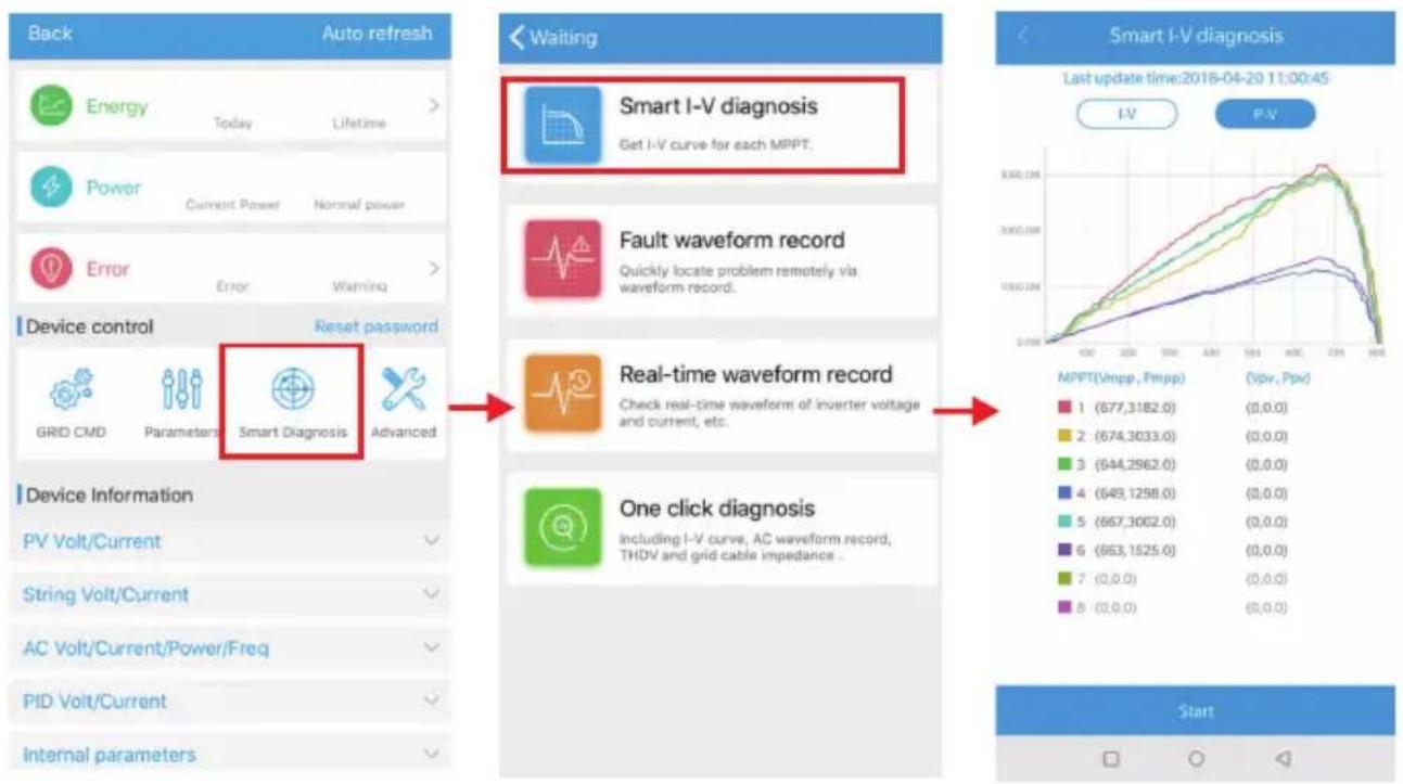
Fig 8.39
F.Fault recording detection
Remote, fast and accurate fault location (Fig 8.40).
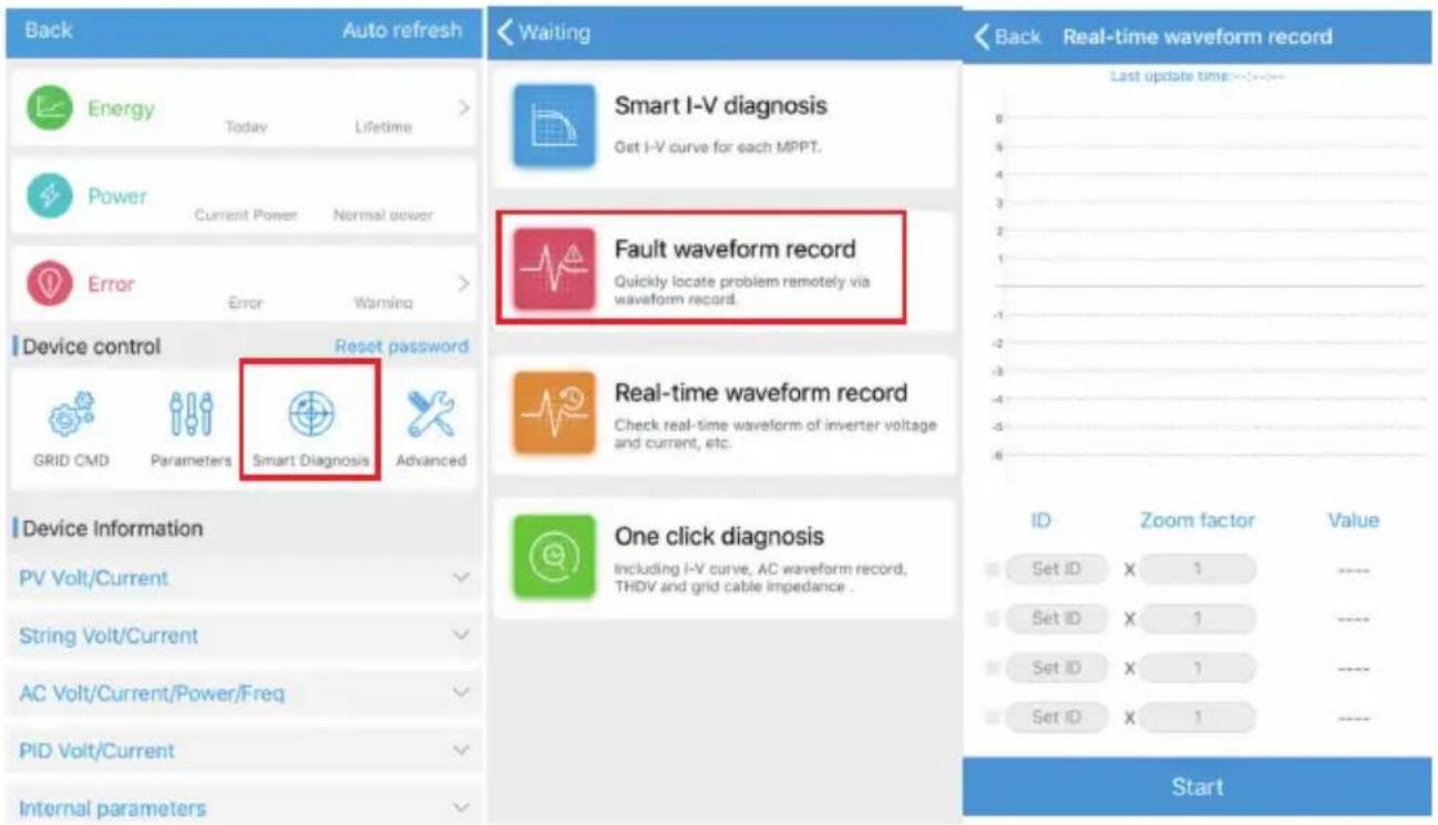
Fig 8.40
G. Real-time recording detection
Inverter voltage and current quality can be observed in real time (Fig 8.41).
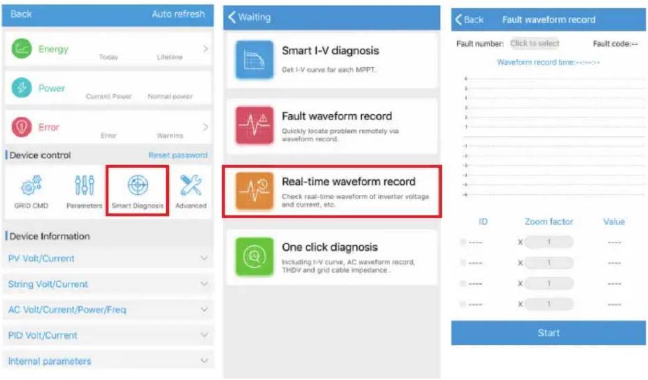
Fig 8.41
H. One click diagnosis
I-V curve diagnosis, grid waveform, THDV and cable impedance detection all at one click(Fig 8.42).
I. High level setting
According to the register address set parameters (professionals).
J.Device information
Check PV voltage/current, string voltage/current, AC voltage/current/power/frequency, PID voltage/current, internal parameters and device detail information and parameters (Fig 8.43).
flowchart
graph TD
    A["Device control"] --> B["Reset password"]
    B --> C["Parameters: Smart Diagnosis Advanced"]
    C --> D["Device Information"]
    D --> E["PV Volt/Current"]
    E --> F["String Volt/Current"]
    F --> G["AC Volt/Current/Power/Freq"]
    G --> H["PID Volt/Current"]
    H --> I["Internal parameters"]

    J["Waiting"] --> K["Smart I-V diagnosis"]
    K --> L["Select item(s): I-V/P-V curve, Grid voltage waveform, Grid voltage harmonics (THDV), Grid cable impedance, Select all, Yes"]

    M["Back"] --> N["One click diagnosis"]
    N --> O["Grid voltage waveform"]

    P["One click diagnosis"] --> Q["Select all, Yes"]

    R["Back"] --> S["Smart I-V diagnosis"]
    S --> T["A"]
    T --> U["I-V"]
    T --> V["P-V"]

    W["Back"] --> X["One click diagnosis"]
    X --> Y["Grid voltage harmonics (THDV)"]

    Z["Back"] --> AA["Smart I-V diagnosis"]
    AA --> AB["A"]
    AB --> AC["I-V"]
    AB --> AD["P-V"]

    AE["Back"] --> AF["One click diagnosis"]
    AF --> AG["A"]
    AG --> AH["I-V"]
    AG --> AI["P-V"]

    AI --> AJ["MPPT(Vac, Isc) (Vpv, lpv)"]
    AJ --> AK["(-,-,-) (-,-,-) (-,-,-) (-,-,-) (-,-,-) (-,-,-)"]

    AL["Back"] --> AM["One click diagnosis"]
    AM --> AN["Grid voltage waveform"]

    AO["Back"] --> AP["One click diagnosis"]
    AP --> AQ["Grid voltage harmonics (THDV)"]

    AR["Back"] --> AS["One click diagnosis"]
    AS --> AT["R Phaser: Q"]
    AS --> AU["S Phaser: Q"]
Fig 8.42
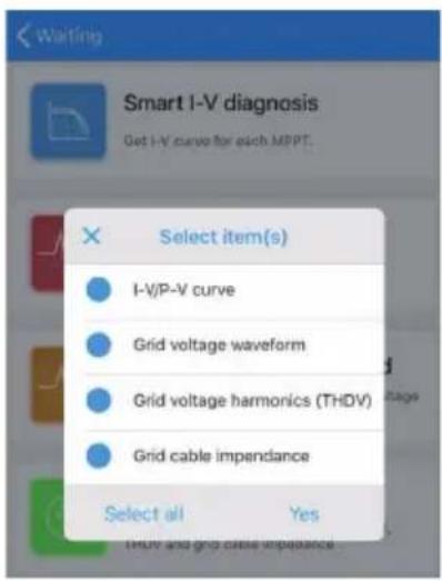
Fig 8.43
8.2.2 U Disk Monitoring
Refer to 6.3.2 USB to WIFI/ U disk communicate connection, the local monitoring of U disk can realize the functions of software burning, fault recording, curve analysis and realtime recording. Details are as follows:
1>Firmware Programming
Create the bconfig.txt file under the root of the U disk, write to the following content, then insert the U disk to programming. Note the M3 program needs to be programming at last time.
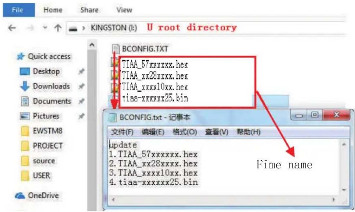
Fig 8.44
2>Fault Recording
Create the bconfig.txt file under the root of the U disk, write the following content, then insert the U disk that can be read fault information, then generates a form under the files in the root directory. A total of 60 fault recording information is stored, the latest Numbers is 0.
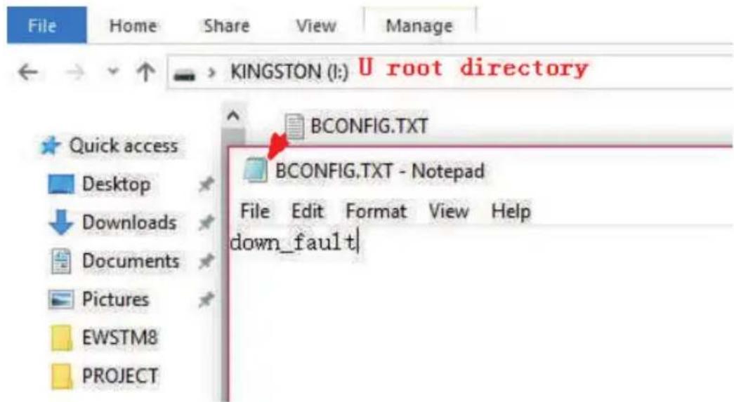
Fig 8.45
3>Curve Analysis
Create the bconfig.txt file under the root of the U disk, write the following content, the insert U disk to record I-V curve, then generates a form under the files in the root directory.
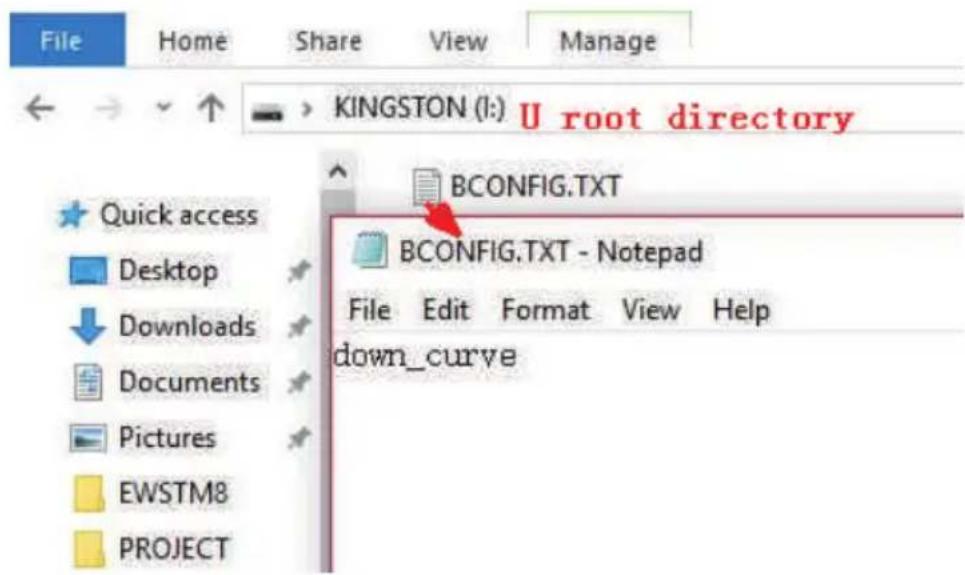
Fig 8.46
4>Real Time Recording
Create the bconfig.txt file under the root of the U disk, write the following content, then insert U disk to read real time recording information, then generates a form under the files in the root directory, the form record's waveform is consistent with the ID of the command setting.
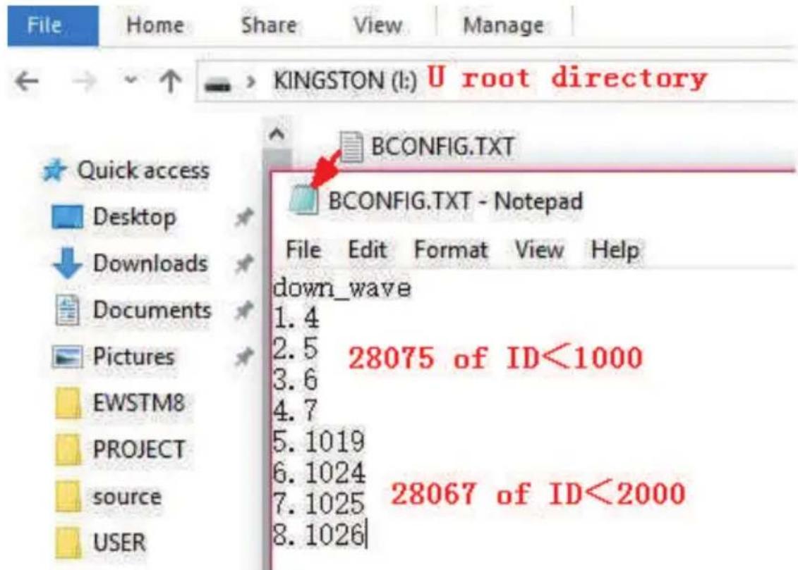
Fig 8.47
9 System Maintenance
9.1 Routine Maintenance
9.1.1 Cleaning Inverter
 DANGER DANGER | • Before any operation, please disconnect the DC switch and AC switch, and wait for at least 5 minutes until internal capacitance discharge completely. |
1>Check the ambient temperature and dust of the inverter, clean the inverter when necessary.
2>Observe whether the air outlets is normal, when necessary, clean the air outlets or clean the fan step by step, steps refer to 9.1.2.
9.1.2 Fan Maintenance
 DANGER DANGER | It must be carried out by qualified, trained personnel and comply with all prevailing local code and regulations.Please disconnect the DC switch and AC switch before any operation, and wait for at least 5 minutes until the internal bus capacitance discharge completely. |
 WARNING WARNING | Do not use the air pump cleaning fan, which may cause fan damage. |
When the Growatt MAX 175-253KTL3-X HV series inverter work in high temperature environment, good ventilation and heat dissipation can effectively reduce the chance of load derating. Inverter equipped with internal cooling fans, when the internal temperature is too high, the fans work in to reduce the internal temperature. When the inverter is derating because of the internal temperature is too high, the following are the possible reasons or solutions:
1) Fan is blocked or the heat sink gathers too much dust, it needs to clean the fan, fan cover or heat sink.
2) Fan is damaged, it need to replace the fan.
3) Poor ventilation of the installation location, it needs to select the appropriate in stallation location according to the basic installation requirements.
Fan cleaning and replacement procedure:
1>Please ensure that the DC side and AC side of the inverter have been disconnected before cleaning or replacement of the fan.
1) Turn off DC switch.
2) Disconnect DC terminals from inverter(Users need tools to disconnect the DC connection terminals).
3) Open the AC side circuit breaker or switch.
2>Remove the screws on the fan guards with a cross screwdriver. it is shown as below.
natural_image
Technical line drawing of a mechanical device with internal components and mounting bracket (no text or symbols)Fig 9.1
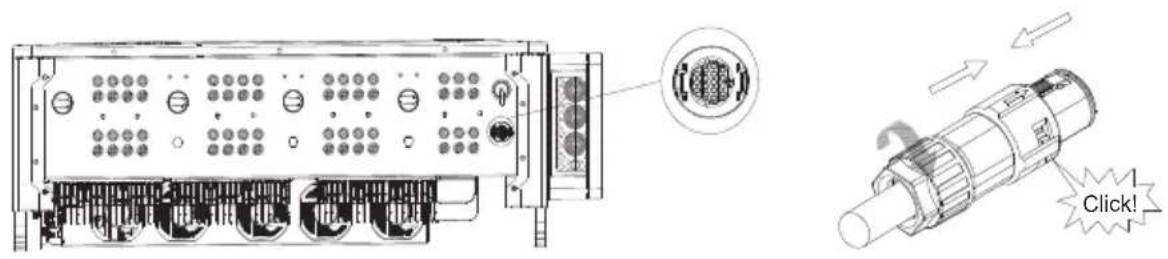
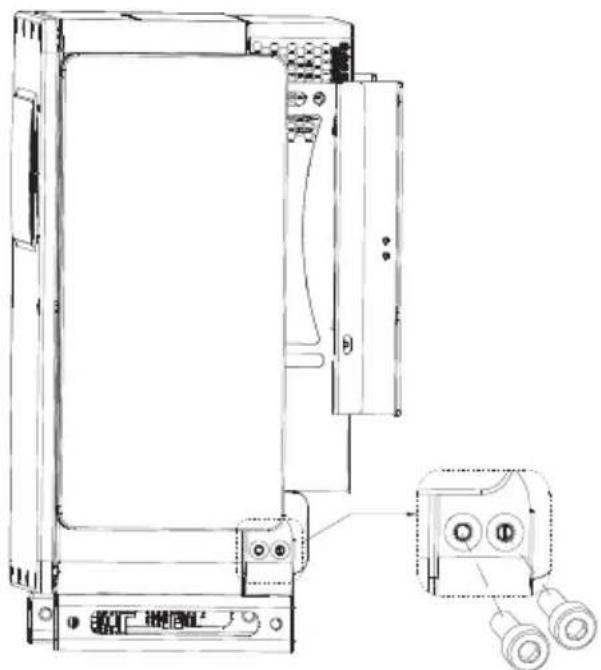
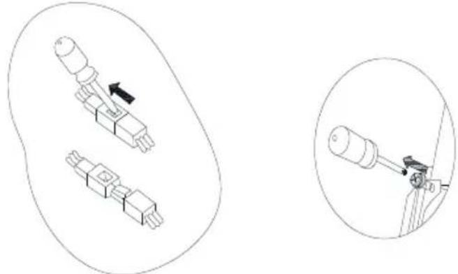
3>Disconnect the wire connector of the fans with a flat head screw driver and remove the fans from the fan guards, it is shown as below.
natural_image
Diagram showing two mechanical components with an arrow indicating direction, and a close-up of a cylindrical component being inserted (no text or symbols present)Fig 9.2
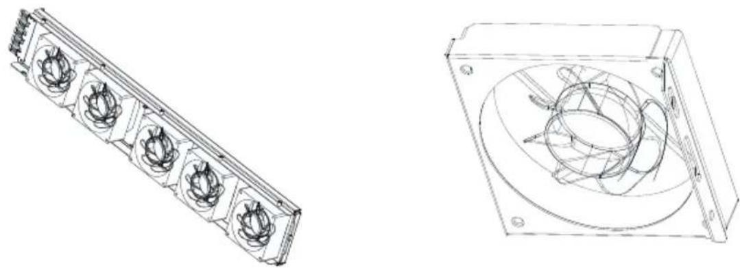
natural_image
Technical line drawings of a mechanical component with two views: one showing a multi-layered panel and the other a circular housing (no text or symbols)Fig 9.3
Notice: MAX 175-253KTL3-X HV series inverter has seven fans□ internal fan*2Pcs,external fan*5Pcs).
4>Clean fan, fan guards and heat sink or replace fan.
1) Clean the fan and fan guards with air pump, brush or a damp cloth.
2) Remove each fan separately for cleaning if necessary.
3) Remove the fan that need to replace with a cross screwdriver, replace a new fan.
4) Tidy up the wire.
5>Install the fan, fan guard fixed and the inverter again.
9.2 Trouble Shooting

DANGER
- It must be operated by well-trained professional electrical technicians and abide by this manual.
- Normally grounded conductors may be ungrounded and energized when a PV isolation low is indicated.
- Risk of electric shock.
9.2.1 Warning
Warnings identify the current status of the inverter(Max), warnings do not related to a fault and it does not affect the normal running of the inverter. When a warning with a number after it appears in the display, it indicates a warning code and is usually cleared through an orderly shutdown/re-set or a self-corrective action performed by the inverter.
| Warning | Description | Suggestion |
| Warning 200 | String Fault | 1.After shutdown,check the panel is normal.2.Contact Growatt. |
| Warning 201 | String abnormal | 1.After shutdown,check the panel is normal.2.Contact Growatt. |
| Warning 202 | DC SPD warning | 1.After shutdown,check the DC SPD.2.Contact Growatt. |
| Warning 203 | PV Circuit short | 1.Check if the PV circuit is short-circuited.2.Contact Growatt. |
| Warning 204 | Dryconnect function abnormal | 1.After shutdown,check the dry Dryconnect wiring.2.Contact Growatt. |
| Warning 205 | PV Boost driver abnormal | 1.Restart inverter.2.Contact Growatt. |
| Warning 206 | AC SPD warning | 1.After shutdown,check the AC SPD.2.Contact Growatt. |
| Warning 207 | USB Over-Current | 1.unplug the U disk.2.Re-access U disk after shutdown.3.Contact Growatt. |
| Warning 208 | DC Fuse Open | 1.After shutdown,check fuse.2.Contact Growatt. |
| Warning 209 | PV Voltage High | 1.Immediately disconnect the DC switch and check the voltage.2.Contact Growatt. |
| Warning 210 | PV Reversed | 1.Check PV input terminals.2.Contact Growatt. |
| Warning 219 | PID function abnormal | 1.Restart inverter.2.If error message still exists,contact manufacturer. |
| Warning 220 | Sting Disconnect | 1.Check string Connect is normal.2.If error message still exists,contact manufacturer. |
| Warning 221 | Sting Current Unblance | 1.Check Pv panel is normal.2.If error message still exists,contact manufacturer. |
| Warning 303 | Output overload | 1.Reduce the output power.2.Contact Growatt. |
| Warning 304 | CT open circuit | 1.Check CT wiring.2.Contact Growatt. |
| Warning 305 | CT is reversed | 1.Check if the CT wiring is reversed.2.Contact Growatt. |
| Warning 306 | CT communication failed | 1.Check CT communication wiring.2.Contact Growatt. |
| Warning 307 | Wireless CT pairing timed out | 1.Check communication wiring.2.Contact Growatt. |
| Warning 308 | Meter open circuit | 1.Check meter wiring.2.Contact Growatt. |
| Warning 309 | The meter reversed | 1.Check if the meter wiring is reversed.2.Contact Growatt. |
| Warning 310 | Ground zero detection abnormal | 1.After shutdown, Check whether the ground wire is connected well.2.Contact Growatt. |
| Warning 400 | Fan function abnormal | 1.After shutdown,Check the fan connection.2.Replace the fan.3.Contact Growatt. |
| Warning 401 | Meter abnormal | 1.Check if the communication between the inverter and the meter is abnormal.2.Check if the meter is on. |
| Warning 402 | The communication between the optimizer and the inverter is abnormal | 1.Check if the optimizer is turned on.2.Check the connection between the optimizer and the inverter. |
| Warning 403 | String abnormal | 1.After shutdown,check the panel is normal.2.Contact Growatt. |
| Warning 404 | EEPROM abnormal | 1.Restart inverter.2.Contact Growatt. |
| Warning 405 | Firmware version abnormal | 1.Restart inverter.2.Contact Growatt. |
| Warning 406 | Boost module error | 1.Restart inverter.2.Contact Growatt. |
| Warning 407 | Over Temperature | 1.Restart inverter.2.Contact Growatt. |
| Warning 408 | NTC broken | 1.Restart inverter.2.Contact Growatt. |
| Warning 409 | Reactive abnormal | 1.Check if shinemaster is abnormal.2.Contact Growatt. |
| Warning 410 | CPU Run abnormal | 1.Restart inverter.2.If error message still exists, contact manufacturer. |
| Warning 411 | synchronization signal Abnormal | 1.Check the synchronizing signal is abnormal.2.If error message still exists, contact manufacturer. |
| Warning 412 | The grid-connected startup condition of the inverter is not met | 1.Check whether the grid voltage is out of range or whether the grid-connected voltage setting of the inverter is correct.2.Check whether the PV voltage is too high or too low.3.Restart the inverter. If error message still exists, contact manufacturer. |
Notice: MAX 175-253KTL3-X series inverter has two external fans and five Internal fan. If the suggestions do not work, please contact to Growatt.
9.2.2 Error
Errors codes identify a possible equipment failure, fault or incorrect inverter setting or configuration, any or all attempts to correct or clear a fault must be performed by qualified personnel.
Typically, the error code can be cleared once the cause or fault is removed.
Some of error code as table shows below, may indicate a fatal error and require you to contact the supplier or Growatt for help.
| Error | Description | Suggestion |
| Error 200 | AFCI Fault | 1. After shutdown, check the panel terminal.2. Restart inverter.3. Contact Growatt. |
| Error 201 | Residual I High | 1. Restart inverter.2. Contact Growatt. |
| Error 202 | PV Voltage High | 1. Immediately disconnect the DC switch and check the voltage.2. Contact Growatt. |
| Error 203 | PV Isolation Low | 1. After shutdown, check if the panel shell is reliably grounded.2. Contact Growatt. |
| Error 204 | PV Reversed | 1. After shutdown, check PV input terminals.2. Contact Growatt. |
| Error 300 | AC V Outrange | 1. Check grid voltage.2. Contact Growatt. |
| Error 301 | AC terminals reversed | 1. Check AC terminals.2. Contact Growatt. |
| Error 302 | No AC Connection | 1. After shutdown, check AC wiring.2. Contact Growatt. |
| Error 303 | NE abnormal | 1. After shutdown, ensure that the ground wire is reliably connected.2. Contact Growatt. |
| Error 304 | AC F Outrange | 1. Check the frequency is in the range of specification or not.2. Contact Growatt. |
| Error 305 | Output overload protected | 1. Check output load, Reduce the output power.2. Contact Growatt. |
| Error 306 | CT is reversed | 1. Check if the CT wiring is reversed.2. Contact Growatt. |
| Error 307 | CT communication failed | 1. Check CT communication wiring.2. Contact Growatt. |
| Error 308 | Wireless CT pairing timed out | 1. Pairing between machine and CT timed out. Re-pair.2. Contact Growatt. |
| Error 309 | Grid Frequency abnormal | 1.Check grid frequency,and Restart.2.Contact Growatt. |
| Error 310 | Ground zero protected | 1.Confirm whether there is an isolation transformer on the output side.2.For PV- connect ground version,N and PE may be connect. |
| Error 311 | Anti-backflow failure protection | 1.If the error is reported and the machine will be restarted soon, it is a normal protective shutdown.2.Check the CT wiring.3.Contact Growatt. |
| Error 400 | DC component offset abnormality | 1.Restart inverter.2.Contact Growatt. |
| Error 401 | The DC component of the output voltage is too high | 1.Restart inverter.2.Contact Growatt. |
| Error 402 | The DC component of the output current is too high | 1.Restart inverter.2.Contact Growatt. |
| Error 403 | Output current imbalance | 1.Restart inverter.2.Contact Growatt. |
| Error 404 | DC BUS voltage sampling abnormal | 1.Restart inverter.2.Contact Growatt. |
| Error 405 | Relay abnormal | 1.Restart inverter.2.Contact Growatt. |
| Error 406 | initialization mode abnormal | 1.Restart inverter.2.Contact Growatt. |
| Error 407 | Auto-detection failed | 1.Restart inverter.2.Contact Growatt. |
| Error 408 | NTC Temperature too high | 1.Restart inverter.2.Contact Growatt. |
| Error 409 | Bus voltage abnormal | 1.Restart inverter.2.Contact Growatt. |
| Error 410 | The voltage of the flying capacitor abnormal protection | 1.Restart inverter.2.Contact Growatt. |
| Error 411 | Communication fault | 1.Restart inverter.2.Contact Growatt. |
| Error 412 | Temperature sensor abnormal | 1.Restart inverter.2.Contact Growatt. |
| Error 413 | IGBT drive fault | 1.Restart inverter.2.Contact Growatt. |
| Error 414 | EEPROM fault | 1.Check if shinemaster is abnormal.2.Contact Growatt. |
| Error 415 | Internal power test fail | 1.Restart inverter.2.Contact Growatt. |
| Error 416 | Over current protected | 1.Restart inverter.2.Contact Growatt. |
| Error 417 | System communication protocol mismatch | 1.Restart inverter.2.Contact Growatt. |
| Error 418 | Firmware version abnormal | 1.Restart inverter.2.Contact Growatt. |
| Error 419 | Firmware and hardware versions do not match | 1.Check firmware version.2.Contact Growatt. |
| Error 420 | GFCI Module damage | 1.Restart inverter.2.Contact Growatt. |
| Error 421 | CPLD abnormal | 1.Restart inverter.2.Contact Growatt. |
| Error 422 | Sampling is inconsistent | 1.Restart inverter.2.Contact Growatt. |
| Error 423 | AC PWM Bypass Protect | 1.Restart inverter.2.If error message still exists,contact manufacturer. |
| Error 424 | INV current abnormal | 1.Restart inverter.2.If error message still exists,contact manufacturer. |
| Error 425 | AFCI self-test fault | 1.Restart inverter.2.Contact Growatt. |
| Error 426 | PV current abnormal | 1.Restart inverter.2.Contact Growatt. |
| Error 427 | AC current abnormal | 1.Restart inverter.2.Contact Growatt. |
| Error 428 | Boost Short Out | 1.Contact Growatt. |
| Error 429 | Bus voltage softstart fail | 1.Restart inverter.2.Contact Growatt. |
| Error 431 | Monitoring chip BOOT verification failed | 1.Restart inverter.2.Contact Growatt. |
10 Specification
| Specifications\Model | MAX175KTL3-X HV | MAX185KTL3-X HV | MAX196KTL3-X HV | MAX216KTL3-X HV |
| Input Data(DC) | ||||
| Max.recommended PV power(for module STC) | 262500W | 277500W | 294000W | 324000W |
| Max. DC voltage | 1500V | |||
| Start voltage | 500V | |||
| Nominal voltage | 1080V | |||
| MPP voltage range | 500V-1500V | |||
| Full-load MPPT voltage range | 800V-1300V | |||
| No. of MPP trackers | 9 | |||
| No. of PV strings per MPP trackers | 2 | |||
| Max. input current per MPP trackers | 30A | |||
| Max. short-circuit current per MPP trackers | 50A | |||
| DC overvoltage category | Category II | |||
| Output Data(AC) | ||||
| AC nominal power | 175000W | 185000W | 196000W | 216000W |
| Max. AC apparent power | 193000VA | 185000VA | 216000VA | 216000VA |
| Nominal AC voltage/range | 800V640-920VAC | |||
| AC grid frequency/range | 50/60Hz45-55Hz/55-65Hz | |||
| Max. output current | 139.3A | 133.5A | 155.9A | 155.9A |
| Power factor(@nominal) | >0.99 | |||
| Max. inrush current/duration | 20KA/tr:8us,tf:20us | |||
| Max. output facult current/duration | 360A/30us | |||
| Adjustable power factor | 0.8leading ...0.8lagging | |||
| THDi | <3% | |||
| Specifications\Model | MAX175KTL3-X HV | MAX185KTL3-X H | MAX196KTL3-X HV | MAX216KTL3-X HV |
| AC grid connection type | 3W+PE | |||
| AC overvoltage category | Category III | |||
| efficiency | ||||
| Max. efficiency | 99.00% | |||
| Euro-eta | 98.50% | 98.50% | 98.50% | 98.50% |
| Protection devices | ||||
| DC reverse-polarity protection | Yes | |||
| DC switch | Yes | |||
| DC Surge protection | Type II | |||
| Insulation resistance monitoring | Yes | |||
| AC surge protection | Type II | |||
| AC short-circuit protection | Yes | |||
| Grid monitoring | Yes | |||
| Anti-islanding protection | Yes | |||
| Residual-current monitoring unit | Yes | |||
| String monitoring | Yes | |||
| Anti-PID function | Optional | |||
| AFCI protection | Optional | |||
| General data | ||||
| Dimensions (W /H/ D) in mm | 1070*675*340mm | |||
| Weight | 95kg | |||
| Operating temperature range | -30°C - +60°C | |||
| Altitude | 4000m | |||
| Internal consumption at | <1W(Note1) | |||
| Topology | Transformerless | |||
| Cooling | Smart air cooling | |||
| Protection degree | IP66 | |||
| Relative humidity | 0~100% | |||
| DC connection | H4 | |||
| AC connection | OT termina | |||
| Interfaces | ||||
| Display | LED/WIFI+APP | |||
| RS485/USB | Yes | |||
| PLC/GPRS/4G | Optional | |||
| Warranty: 5 /10 years | Optional | |||
| Certificates and approvals | ||||
| Grid regulation | IEC 61683, IEC 60068-2-1, IEC 60068-2-2, IEC 60068-2-14, IEC 60068-2-30, IEC 61727, IEC 62116 | |||
| EMC | IEC/EN 61000-6-2,IEC/EN 61000-6-4 | |||
| Safety | IEC/EN 62109-1,IEC/EN 62109-2 | |||
| Note1: If with AC power supply function, self-consumption at night is less than 25W. | ||||
| Specifications\Model | MAX225KTL3-X HV | MAX230KTL3-X HV | MAX250KTL3-X HV | MAX253KTL3-X HV |
| Input Data(DC) | ||||
| Max.recommended PV power(for module STC) | 337500W | 345000W | 375000W | 379500W |
| Max. DC voltage | 1500V | |||
| Start voltage | 500V | |||
| Nominal voltage | 1080V | 1080V | 1080V | 1080V |
| MPP voltage range | 500V-1500V | |||
| Full-load MPPT voltage range | 800V-1300V | |||
| No. of MPP trackers | 12 | 15 | 12 | 15 |
| No. of PV strings per MPP trackers | 2 | |||
| Max. input current per MPP trackers | 30A | |||
| Max. short-circuit current per MPP trackers | 50A | |||
| DC overvoltage category | Category II | |||
| Output Data(AC) | ||||
| AC nominal power | 225000W | 230000W | 250000W | 253000W |
| Max. AC apparent power | 25000VA | 253000VA | 250000VA | 253000VA |
| Nominal AC voltage/range | 800V640-920VAC | |||
| AC grid frequency/range | 50/60Hz45-55Hz/55-65Hz | |||
| Max. output current | 180.4A | 182.6A | 180.4A | 182.6A |
| Power factor(@nominal) | >0.99 | |||
| Max. inrush current/duration | 20KA/tr:8us,tf:20us | |||
| Max. output facult current/duration | 360A/30us | |||
| Adjustable power factor | 0.8leading ...0.8lagging | |||
| THDi | <3% | |||
| AC grid connection type | 3W+PE | |||
| AC overvoltage category | Category III | |||
| efficiency | ||||
| Max. efficiency | 99.00% | 99.00% | 99.00% | 99.00% |
| Euro-eta | 98.5% | |||
| Protection devices | ||||
| DC reverse-polarityprotection | Yes | |||
| DC switch | Yes | |||
| DC Surge protection | Type II | |||
| Insulation resistance monitoring | Yes | |||
| AC surge protection | Type II | |||
| AC short-circuit protection | Yes | |||
| Grid monitoring | Yes | |||
| Anti-islanding protection | Yes | |||
| Residual-current monitoring unit | Yes | |||
| String monitoring | Yes | |||
| Anti-PID function | Optional | |||
| AFCI protection | Optional | |||
| General data | ||||
| Dimensions (W /H / D) in mm | 1070*675*340mm | |||
| Weight | 99kg | 109kg | 99kg | 109kg |
| Operating temperature range | -30°C - +60°C | |||
| Altitude | 4000m | |||
| Model Specifications | MAX 225KTL3-X HV | MAX 230KTL3-X HV | MAX 250KTL3-X HV | MAX 253KTL3-X HV |
| Internal consumption at | <1W(Note1) | |||
| Topology | Transformerless | |||
| Cooling | Smart air cooling | |||
| Protection degree | IP66 | |||
| Relative humidity | 0~100% | |||
| DC connection | H4 | |||
| AC connection | OT termina | |||
| Interfaces | ||||
| Display | LED/WIFI+APP | |||
| RS485/USB | Yes | |||
| PLC/GPRS/4G | Optional | |||
| Warranty: 5 /10 years | Optional | |||
| Certificates and approvals | ||||
| Grid regulation | IEC 61683, IEC 60068-2-1, IEC 60068-2-2, IEC 60068-2-14, IEC 60068-2-30, IEC 61727, IEC 62116 | |||
| EMC | IEC/EN 61000-6-2, IEC/EN 61000-6-4 | |||
| Safety | IEC/EN 62109-1, IEC/EN 62109-2 | |||
| Note1: If with AC power supply function, self-consumption at night is less than 25W. | ||||
11 Decommissioning
If the inverter does not operate in the future, it needs to be properly disposed. The steps are as follows:
1> Disconnect the external AC short circuit and prevent reconnection due to misoperation.
2> Turn the DC switch to "OFF" position.
3> Wait at least 5 minutes until the internal capacitor discharge is completed.
4> Disconnect the AC connector.
5> Disconnect DC connector.
6> Remove the inverter from the wall.
7> Disposing of the inverter.
11.1 Disposing Of The MAX 175-253KTL3-X Series Inverter
Do not dispose of MAX 175-253KTL3-X HV series inverter together with household waste. Please accordance with the disposal regulations for electronic waste which apply at the installation site at that time. Ensure that the old unit and, where applicable, any accessories are disposed of in a proper manner.
12 Quality assurance
Please refer to related file.
Contact 13
If you have technical problems concerning our products, contact your installer or Growatt, please provide information below for better support.
1> Inverter type
2> Serial number of inverter
3> Error code of inverter
4> LED status of inverter
5> DC input voltage of inverter (Modules information)
6> Inverter communication method
Shenzhen Growatt New Energy CO., Ltd.
4-13/F, Building A, Sino-German (Europe) Industrial Park, Hangcheng Blvd, Bao'an District, Shenzhen, China
T +86 755 2747 1942
E service@ginverter.com
W www.ginverter.com

natural_image
Stylized globe with leafy tree and globe, symbolizing global nature (no text or symbols)
Download Manual


Growatt New Energy
Shenzhen Growatt New Energy CO., Ltd.
4-13/F, Building A, Sino-German (Europe) Industrial Park, Hangcheng Blvd, Bao'an District, Shenzhen, China
T +86 755 2747 1942
E service@ginverter.com
W www.ginverter.com
GR-UM-255-A-03