ERTC-01-DIN - Electronic timer ENTES - Free user manual and instructions
Find the device manual for free ERTC-01-DIN ENTES in PDF.


| Product Type | Programmable Time Relay |
| Model | ERTC-01-DIN |
| Operating Voltage | 230 V AC / 120 V AC (190-260 V AC / 90-140 V AC) |
| Frequency | 50/60 Hz |
| Power Consumption | < 3 VA |
| Output Contact | 1 Change-Over, 8A / 2000VA |
| Time Range | 1.0 sec to 100 hours |
| Functions | On Delay, Off Delay, Down Timer, Flasher |
| Accuracy | ±0.5% or ±20 ms (whichever greater) |
| Repeatability | ±0.1% |
| Display | Red LED display |
| Programming Method | Front panel buttons (SET, UP, DOWN) |
| Inputs (Optoisolated) | Start, Stop, Reset (active low to GND) |
| Dimensions | PK-20 housing (ERTC-01): 22 x 18 x 18.5 cm (package) |
| Weight | 0.25 kg |
| Mounting | Rail mounting (DIN) |
| Protection Degree | IP40 front panel, IP20 terminal covers |
| Equipment Protection | Double insulation (Class II) |
| Ambient Temperature | -5°C to +50°C |
| Wire Cross Section | 2.5 mm² |
| Box Material | Non-flammable (Yellow Certificate No. 187982) |
| Reset Time | ≤ 80 ms |
| Package Dimensions (ERTC-01) | 22 x 18 x 18.5 cm |
| Maintenance | Clean with dry cloth only; no solvents |
Frequently Asked Questions - ERTC-01-DIN ENTES
User questions about ERTC-01-DIN ENTES
0 question about this device. Answer the ones you know or ask your own.
Ask a new question about this device
Download the instructions for your Electronic timer in PDF format for free! Find your manual ERTC-01-DIN - ENTES and take your electronic device back in hand. On this page are published all the documents necessary for the use of your device. ERTC-01-DIN by ENTES.
USER MANUAL ERTC-01-DIN ENTES
ERT/ERTC-01 is a microcontroller controlled programmable time relay device with a wide range of time scale designed to operate in one of 4 different functions that are On delay, Off delay, Down timer, Flasher modes. Output relay is controlled by set value that can be set between 1.0 sec – 100 hours. Programmed function and set values are recorded at non-volatile memory. Functions and set values can be programmed easily by buttons on the front panel. ERT/ERTC-01 has optically isolated Start, Stop and Reset inputs.
Functions:
On Delay: In the On Delay mode, after the device is energized, the timer starts to count up and when it reaches the adjusted time, the relay is energized. (dLYOn)
Off Delay: In the Off Delay mode, after the device is energized and with start input, the relay is energized and becomes de-energized at the end of the time adjusted by the user. (dLYOFF)
Down Timer: In the Down Timer mode, after the device is energized, the down counter starts to count down from the time adjusted by the user and when it reaches zero, the relay is energized. (dO Cnt)
Flasher: In the Flasher mode, after the device is energized, when tOFF time ends the relay is energized and becomes de-energized at the end of the tOn delay (FLSHEr). The starting mode of the flasher mode can be chosen with StOFF or StOn. In the StOFF mode flasher starts with tOFF and energized after the tOFF value, then continues to tOn mode. In the StOn mode flasher starts with tOn and deenergized after the tOn value, then continues to tOFF mode. The Flasher function is continuously repetitive. Inputs: Start input is used to begin counting, Stop input is used to end counting and Reset input is used to clear counter in dIYOn,dlyOFF and FLSHEr. In dO Cnt mode reset, sets the dO Cnt value. One of this three inputs activated by connecting them to GND.
Function Select:
The device is programmed by pressing the SET button for 3 secs. Then program menu starts with blinking of dLYOn. With UP and DOWN button desired mode dLYOn, dLYOFF, dO Cnt or FLSHER, and the mod led blinks. After pressing the SET button display stops blinking that this mode is chosen. Pressing once to SET button shows the old time value of this mode with blinking and this could be adjusted with UP and DOWN button. Pressing to UP or DOWN button continuous, increases or decreases the left digit. For all the other functions, the left digit is changed the same way. After adjusting the time value, pressing the SET button stops the display blinking, but led button still blinks (Note that this setting operations need a few steps more for FLSHER mode). After pressing the SET button last time mod led stops blinking, desired mod and value are set and writed to non-volatile memory.
Device can be started to counting with start input. With stop input device stops counting until stop input is deactivated. Reset input resets the time values. Device can be started with pressing set and up button at same time (same function with start input). Pressing set and down button at the same time stops counting. (same function with stop input). Pressing DOWN and UP button at the same time resets counting (same function with RESET input).
Precautions For Installation and Safe Use
Failure to follow those instructions will result in death or serious injury.
- Disconnect all power before working on equipment.
- When the device is connected to the network, do not remove the front panel.
- Do not try to clean the device with solvent or the like. Only clean the device with a dried cloth.
- Verify correct terminal connections when wiring.
• Electrical equipment should be serviced only by your compedent seller.
- Only for rack panel mounting.

No responsibility is assured by the manufacturer or any of its subsidiaries for any consequences arising out of the use of this material.

flowchart
graph TD
    A["3 sec SET"] --> B["d L Y O n"]
    B --> C["d L Y OFF"]
    C --> D["d O C n t"]
    D --> E["F L S H E r"]
    E --> F["SET"]
    F --> G["SET"]
    G --> H["01.25.50"]
    H --> I["15.40.35"]
    I --> J["SET"]
    J --> K["SET"]
    K --> L["Start"]

    M["Function LEDs"] --> N["ON Delay"]
    M --> O["OFF Delay"]
    M --> P["Down Counter"]
    M --> Q["Flasher"]

    R["Menu buttons"] --> S["Down"]
    R --> T["SET"]
    R --> U["Up"]

    V["tOFF time setting"] --> W["tOn time setting"]
    W --> X["StOF or StOn setting"]
    X --> Y["Start"]

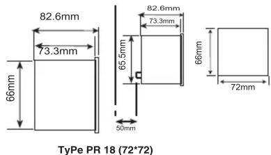
    Z["CE Pin Specification"] --> AA["66mm"]
    Z --> AB["72mm"]

flowchart
graph TD
    A["On Delay"] --> B["Relay Output"]
    B --> C["Start On Delay Time"]
    D["Off Delay"] --> E["Relay Output"]
    E --> F["Start Off Delay Time"]
    G["Down Counter"] --> H["Relay Output"]
    H --> I["Start Down Counter Time"]
    J["Flasher-StOn Mode"] --> K["Relay Output"]
    K --> L["Start tOn Time"]
    L --> M["tOFF Time"]
    M --> N["tOn Time"]
    O["Flasher-StOFF Mode"] --> P["Relay Output"]
    P --> Q["Start tOFF Time"]
    Q --> R["tOn Time"]
    R --> S["tOFF Time"]
Technical Data
Operating Voltage(Un) : 230 V AC / 120 V AC
Operating Range (ΔU): 190 - 260 V AC / 90 - 140 V AC
Operating Frequency (f) : 50/60 Hz
Power Consumption : < 3 VA
Output Contact :1 Change-Over 8A/2000VA
Error :±%0.5 or ±20msec.(Which is higher)
Repetition Error :±%0.1
Reset Time :<= 80 msec.
Ambient Temperature : -5°C; +50°C
Display : Red LED display
Dimension : PK-20 (ÉRTC-01) , PR-18 (ERT-01)
Equipment Protection : Double Insulation ( )
Degree of Protection : IP 40 (Front Panel)
IP 20 (Terminal Covers)
Box Material : Nonflammable, (Yellow Certificate no:187982)
Wire Cross section (for terminal) : 2.5 mm
Weight : 0.25 kg
Installation
Package Diemensons
: Rail Mounting (ERTC-01), Class III (ERT-01)
: 22 x 18 x 18.5 cm (ERTC-01)
: 37 x 21.5 x 17 cm (ERT-01)

Dimensions (ERT-01):

Duvar
Connection Diagram (ERT-01):

*No need of a cantillator in the installation area
Brand : ENTES
Model : ERTC-01-DIN
Category : Electronic timer