LCT 640 TS - Phone Lewitt - Free user manual and instructions
Find the device manual for free LCT 640 TS Lewitt in PDF.

| Product Type | Large-diaphragm condenser microphone |
| Brand | Lewitt |
| Model | LCT 640 TS |
| Polar Patterns | Cardioid, omnidirectional, figure-8 |
| Frequency Response | 20 Hz - 20 kHz |
| Sensitivity | 25 mV/Pa at 1 kHz |
| Maximum SPL | 142 dB (0.5% THD) |
| Dynamic Range | 125 dB (A-weighted) |
| Signal-to-Noise Ratio | 78 dB (A-weighted) |
| Self-Noise | 16 dB (A-weighted) |
| Power Supply | 48 V phantom power |
| Dimensions | 158 mm x 52 mm (6.22 x 2.05 in) |
| Weight | 345 g (12.17 oz) |
| Connector | 3-pin XLR |
| Accessories Included | Shock mount, metal pop filter, magnetic pop filter, flight case, manual |
| Maintenance | Clean with soft dry cloth; avoid moisture; store in case |
| Safety | Use only 48V phantom; do not open; avoid dropping |
| Spare Parts / Repairability | Contact Lewitt service; cartridge and electronics are not user-serviceable |
Frequently Asked Questions - LCT 640 TS Lewitt
User questions about LCT 640 TS Lewitt
0 question about this device. Answer the ones you know or ask your own.
Ask a new question about this device
Download the instructions for your Phone in PDF format for free! Find your manual LCT 640 TS - Lewitt and take your electronic device back in hand. On this page are published all the documents necessary for the use of your device. LCT 640 TS by Lewitt.
USER MANUAL LCT 640 TS Lewitt
RAW AND NON-DESTRUCTIVE
MULTI-PATTERN FLAGSHIP WITH THE OPTION TO ADJUST THE POLAR PATTERN AFTER THE RECORDING
// LCT 640 TS
USER MANUAL

LEWITT
// Index
-
Introduction......3
-
Box contents 3
-
Features 4
4.User interface 6
- Operating modes and setup 7
5.1. Multi-pattern Mode 7
5.2. Dual output Mode 8
- Important facts about polar patterns 9
6.1. How to read a polar pattern diagram....9
6.2. Most common polar patterns and characteristics ..... 10
6.3. Technical background 11
-
How to create different polar patterns manually ..... 11
-
Change pattern with the POLARIZER 12
8.1. Installation MAC....12
8.2.Installation Windows....13
- What to do with a Dual Output Mode? 14
9.1. Automate/change the polar pattern after the recording ..... 14
9.2. Change the direction of the microphone, not only the polar pattern . . 14
9.3. Stereo with only one LCT 640 TS 14
9.4. Stereo recording - the easy way.... 15
- Stereo applications with two LCT 640 TS....15
10.1. XY and Blumlein.... 15
10.2.AB stereo 16
10.3. ORTF....16
-
Perfect Match Technology 17
-
Safety guidelines 18
-
Regulatory information .... 18
1. Introduction
Thank you for choosing the LEWITT LCT 640 TS! In return, we will make your life way easier. Recording with the LCT 640 TS will offer you a level of flexibility you wouldn't have guessed being possible. There are certain developments that fundamentally changed the way how things are being done – Think of the difference of digital photography and analogue photography, or compare the jpg compression with the possibilities the open RAW standard brought, enabling the photographer to change exposure and white balance after the picture has been already taken. The LCT 640 TS provides such a possibility, but now, for music production.
Using both outputs of the LCT 640 TS while recording is like capturing the whole session instead of just recording an isolated source. It adds the freedom of changing the polar pattern dynamically from cardioid all the way to figure-8 during post-production. In fact, while mixing your track, you could still turn your microphone by 180^ although you finished your recording days ago. And we haven't even touched all the possibilities of two LCT 640 TS in a stereo-stereo setup ...
You see, recording with the LCT 640 TS can be different than using any other large-diaphragm condenser microphone: Record now, decide later.
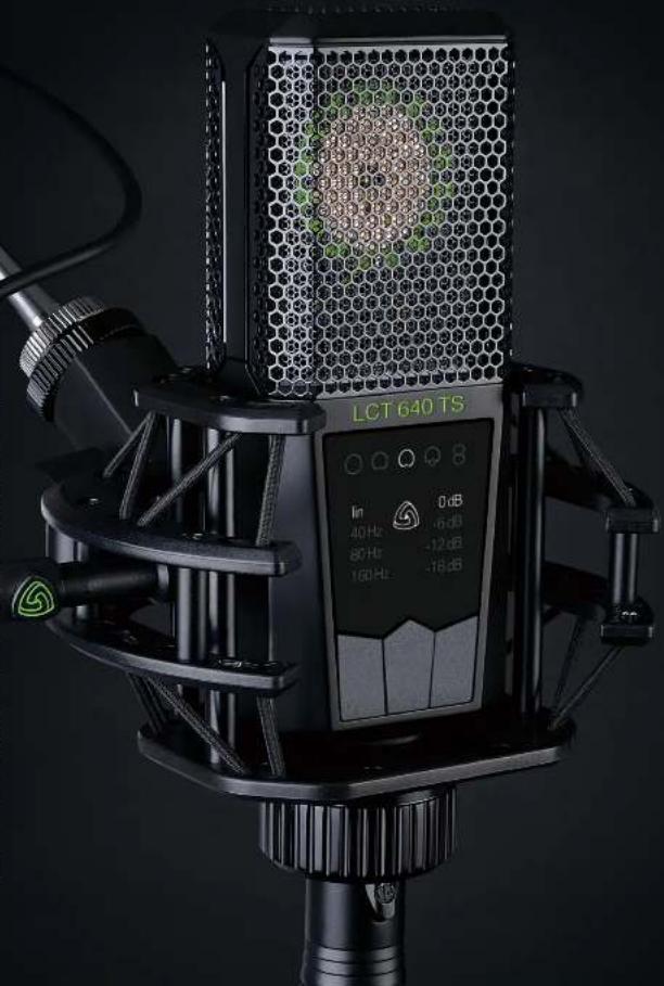
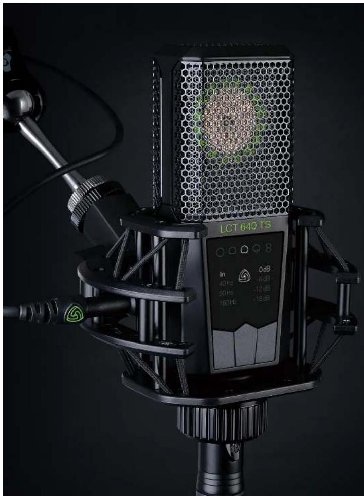
2. Box contents
// LCT 640 TS microphone
// LCT 40 SHx shock mount
// LCT 40 Wx windshield
// LCT 40 PSx Pop Filter
// DTP 40 Lb artificial leather bag
// Black military-grade flightcase

natural_image
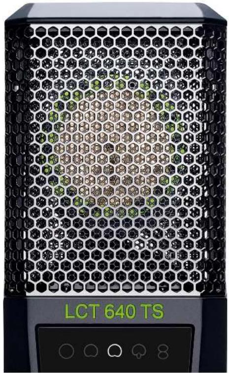
Close-up of a black LCT 640 TS audio recording device with hexagonal grid and control buttons (no readable text beyond branding)3. Features
// Dual Output Mode
The LCT 640 TS provides the signal of the front and the back of the capsule separately. That way any kind of polar pattern from omnidirectional to cardioid, to figure-8 can be realized dynamically. And the most fascinating fact; you can change the polar pattern after the recording during post-production.
// Customized or one-click
Plug in your 3-pin XLR as you would do with any other mic and you get a large diaphragm multi-pattern condenser mic. Plug in the included mini 3-pin XLR and experience all the possibilities of a true next gen recording microphone.
// Stereo functionality
Record stereo with only one LCT 640 TS. Just point the side of the microphone to the source!
// The POLARIZER plug-in
The POLARIZER is a newly developed DAW plug-in. Change or fine-tune the polar pattern during post-production, both on PC and Mac. The POLARIZER supports VST, AU and AAX.
natural_image
Close-up of a black LCT 640 TS audio recording device with hexagonal grid and control buttons (no readable text beyond branding)// Low-cut filters
Low-cut filters eliminate low-frequency sounds to compensate the proximity effect and reduce structure-borne noise.
// Pre-attenuation
Pre-Attenuation reduces the sensitivity of a microphone. Use it to avoid clipping when recording very loud sound sources.
// Key Lock
Makes the 3 pushbuttons inactive, to avoid accidental change of settings.
// Status Indicator
If the input signal is very loud the electronics inside the microphone will distort - in other words, the signal will clip. The Status indicator will blink red to alert the user to adjust the pre-attenuation setting.
// Clipping History
Use the Clipping History to make sure your microphone has not clipped during recording.
// Perfect Match Technology
Every single LCT 640 TS undergoes a series of measurements followed by adjustment of the polarization voltage to achieve exactly the same sensitivity at 1 kHz in every microphone.
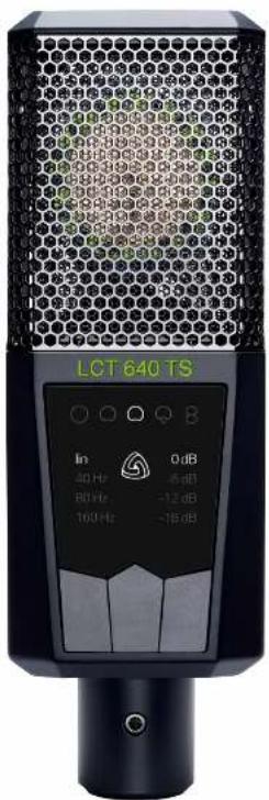
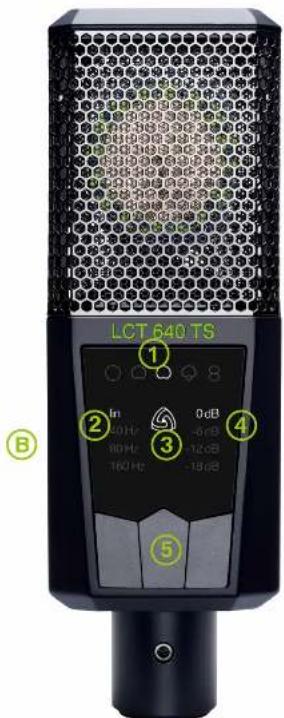
4. User interface
1 // Polar pattern indicator
Use center pushbutton to select polar pattern; omni // wide cardioid // cardioid // supercardioid // figure-8. Only available in Multi-pattern Mode! Not illuminated in Dual Output Mode!
211 Low-cut indicator
Use left pushbutton to change the low-cut settings. Activate the low-cut to get rid of unwanted low frequencies and structure-born noise.
3 // Status indicator
Illuminated white: Multi-pattern mode (standard operation) Illuminated green: Dual Output Mode Flashing red: clipping occurs Not illuminated: key-lock active.
4 // Pre-attenuation indicator
Use right button to select the pre-attenuation. Use this setting to avoid clipping when recording very loud sound sources.
5 // Pushbuttons
Key-lock: Hold the left pushbutton for more than 2 seconds. Now all pushbuttons are locked until you press the left button for 2 seconds again.
Clipping History: Hold the right pushbutton for more than 2 seconds to enter clipping history. If the status indicator flashes green/white no clipping occurred. If the status indicator flashes red/white clipping occurred. The illuminated pre-attenuation symbols show at which pre-attenuation setting the clipping occurred. Press any button for more than 2 seconds to exit clipping history. Once you exit the clipping history or remove 48V the history is deleted.
A
5. Operating modes and setup
Unlike other microphones, the LCT 640 TS features a Dual Output Mode that records the front and back diaphragm of the capsule individually. Ok, that maybe does not sound as spectacular as the bold font indicates, but it definitely is. Put in other words:
Recordings done using the Dual Output Mode can be manipulated in a unique way. Even after the recording session, you can ne-tune the polar pattern seamlessly all the way from omnidirectional to gure-8 as well as turn the recording direction of the microphone by 180° as if you have used these settings during the actual recording.
Adjusting room sound post-recording is just one of the many practical applications that immediately come to mind. You can even x things thought to be un xable; reduce bleeding, etc. Unique stereo setups are made possible; creative freedom have never been as big using just one single microphone. Of course, the LCT 640 TS can be handled as a standard multi-pattern microphone as well. The next section will explain how to set up the microphone for the two modes:
5.1. Multi-pattern Mode
In this mode your LCT 640 TS is being used just like any other multi-pattern condenser microphone. The LCT 640 TS is automatically set to this mode using only the standard 3-pin XLR plug.
// Use a 3-pin XLR cable to connect the LCT 640 TS to your microphone preamp, mixing console or audio interface.
natural_image
Close-up of a black hexagonal device with green and brown patterns, labeled 'LCT 640 TS' at bottom (no other text or symbols visible)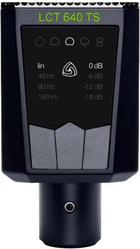
// Turn on 48 V phantom power.
// Status indicator is illuminated white, stating that the microphone is in Multi-pattern Mode.
// Choose one of the five preset polar patterns by pushing the center pushbutton.
// Adjust the settings on the microphone to your needs.
See section 4. User interface for a walkthrough of the UI elements.
5.2. Dual Output Mode
Now this is where the magic starts. Set to Dual Output Mode the LCT 640 TS enables you to change and fine-tune the polar pattern of your mic at any given time before and after the recording.
// Use a standard 3-pin XLR cable to connect output A to your microphone preamp, audio interface or mixing console.
// Use the included adapter and a standard 3-pin XLR cable to connect output B to a second channel either on your microphone preamp, audio interface or mixing console.
// Turn on 48V phantom power on both channels!
// Press and hold center pushbutton for 2 seconds to enter dual output mode.
// Status indicator will light up green.
// Make sure that the input gain is set to the exact same value on both channels. This is essential to create the polar patterns later on.
// Use your mixing console or DAW to create the polar pattern or use our Polarizer plugin here.
// Attention
It takes up to 20 seconds till the microphone reaches its full sensitivity after 48 V.
phantom power is applied.
It takes up to 20 seconds till the switch between polar patterns is complete!
Always apply phantom power to output A for standard operation.
Always apply phantom power to outputs A and B in Dual Output Mode.
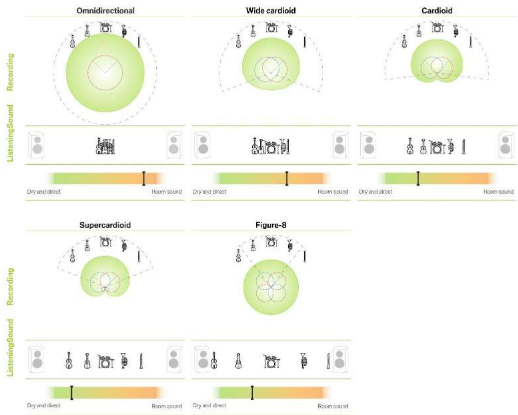
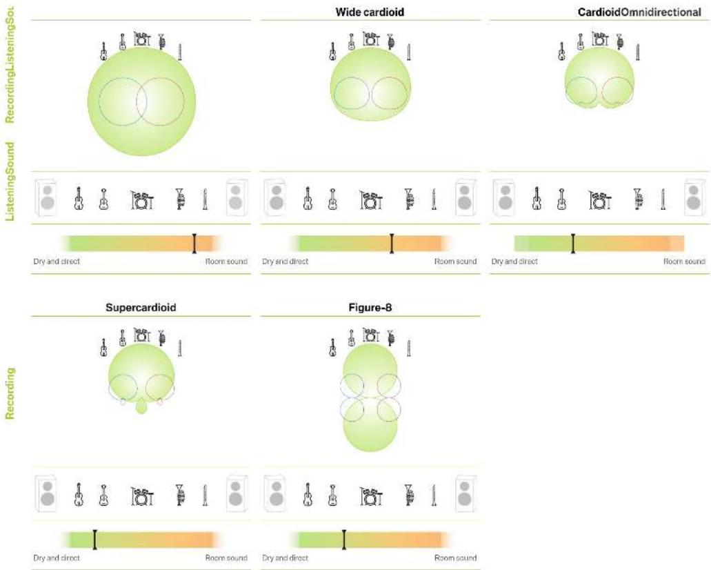
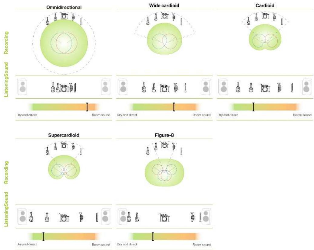
6. Important facts about polar patterns
It is important to understand the basic principles of polar patterns to get the best out of every recording. The polar pattern of a microphone determines the sensitivity on different angles. In other words, it defines how much of the signal will be picked up by the microphone from different directions. By selecting the right pattern, you can avoid unwanted sound sources to bleed into your signal, adjust the mix between dry and room sound or change the frequency response and handling noise sensitivity.
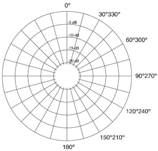
6.1. How to read a polar pattern diagram
First of all, you have to be able to read a polar pattern diagram properly. It contains all necessary information you need to foresee the result during recording. Think of a 360^ field surrounding the microphone. 0^ is the “front” of the microphone and the angle where the microphone has its maximum sensitivity. The scale of the circle consists of smaller circles, each representing a 5 dB decrease in sensitivity. The decibel (dB) is a logarithmic unit to compare two values. If the specification of a cardioid pattern microphone states it has a rear rejection of 25 dB, it means that the most sensitive part ( 0^ ) and the least sensitive part ( 180^ ) are compared. For (sound) pressure, current and voltage +6 dB is double the signal strength, +20 dB leads to 10 times the signal. A typical rear rejection for a cardioid pattern is about -20 dB. Sound coming from the back of the microphone is picked up at 1/10th sensitivity relative to the front signal.
radar
| Angle (°) | Value (dB) | | --------- | ---------- | | 0 | -5 | | 30 | -10 | | 60 | -15 | | 90 | -20 | | 120 | -25 | | 150 | -30 | | 180 | -35 | | 210 | -40 | | 240 | -45 | | 270 | -5 | | 300 | -5 | | 330 | -5 |
natural_image
Solid light green circular shape with no text or symbolsOmnidirectional

natural_image
A plain light green circular shape with no text, symbols, or markings.Wide Cardioid

Cardioid

Supercardioid


Figure-8
6.2. Most common polar patterns and characteristics
// Omnidirectional
The omni pattern has the same sensitivity to sound pressure coming from any direction. Therefore, recordings being done in a bad sounding room using an omni polar pattern might not lead to a satisfying result. In most live situations where the picked up signal is monitored and played back through the PA feedback will definitely occur. It will shine in good sounding rooms and time based stereo recording techniques. The omni pattern picks up very high frequencies with more directivity leading to higher side rejection of the signal for these frequencies (this effect turns the omni into figure-8 at the 16 kHz mark). An omni pattern provides the best bass response, flattest frequency response, and is the least sensitive to handling or wind noise in comparison to all other polar patterns.
// Wide Cardioid
A mix between omni and cardioid with all their characteristics.
// Cardioid
The most commonly used polar pattern is most sensitive at 0^ and least sensitive at 180^ . You cannot go wrong using this for most recording applications. It is easy to get a dry signal as the cardioid pattern blends out a bad sounding room, a noisy fan in the background, etc.
// Supercardioid
Supercardioid is even more directive than a cardioid pattern having a bit more side and a bit less rear rejection. It is very useful in live situations as it allows for very high gain before feedback. It also keeps the signal very dry; you get mainly the direct signal from your sound source.
// Figure-8
The figure-8 pattern has the same sensitivity at 0^ and 180^ , it is the least sensitive at 90^ and 270^ . It is often chosen for various stereo recording techniques (Mid Side, Blumlein). It can also be very helpful in situations where you do not want a signal coming from a 90^ angle to bleed into the microphone.
It has the highest side rejection of all polar patterns making it very useful to deal with signals bleeding into the microphone coming from the side. In live recording situations you can achieve fairly dry recordings although many instruments are recorded in the same room at the same time. In comparison to all other polar patterns it has the least bass response and it is the most sensitive to wind and handling noise.
6.3. Technical background
Every multi-pattern microphone follows the same technical principle: two diaphragms back to back with the electrode between them. Both sides have a cardioid pickup pattern. Mixing these signals together with different levels and phase creates different polar patterns.
// Distance factor
The distance factor describes how far away a directional microphone can be placed in comparison to an omnidirectional microphone while preserving the same ratio of direct and reflected sound.
// Acceptance angle (-3 dB reduction)
The acceptance angle is the angle in which the sensitivity of the microphone is not reduced by more than 3 dB. It is not recommended to place a sound source outside the acceptance angle.
// Maximum reduction
The maximum reduction describes the angle with the least sensitivity of the microphone.
// Rear rejection
Amount of dB the signal is reduced at the angle of maximum reduction.
7. How to create different polar patterns manually with your LCT 640 TS
Of course you can select a preset polar pattern if your microphone is set to Multi-pattern Mode, but let's be honest - that's boring. Wouldn't it be much more exciting to create the different polar patterns with the LCT 640 TS using your mixing console or DAW? It definitely would ...
All you need to do is to record the front and back signal on two different tracks. Make sure to set the gain on both input channels on your preamp to the same value. Then it's just a matter how you set the levels and if you invert the phase on one channel. See the table below for the correct values.
| Omni | Wide cardloid | Cardioid | Super cardloid | Figure-8 | |
| Front Diaphragm Level | 0 dB 0 dB 0 dB 0 dB 0 dB | ||||
| Back Diaphragm Level | 0 dB -10 dB -∞ dB -10 dB 0 dB | ||||
| Front Diaphragm Phase | 0^ 0^ 0^ 0^ 0^ | ||||
| Back Diaphragm Phase | 0^ 0^ 0^ 180^ 180^ | ||||
| Acceptance angle (-3 dB reduction) | -90° 65° | 57° 45° | |||
| Maximum reduction | - | 180° 180° | 126° | 90° | |
| Distance Factor | 1 | 1,38 | 1,73 | 1,93 | 1,73 |
radar
| Angle | Value | |-------|-------| | 0° | -5 dB | | 30° | -10 dB | | 60° | -15 dB | | 90° | -20 dB | | 120° | -25 dB | | 150° | -30 dB | | 180° | -35 dB | | 210° | -40 dB | | 240° | -45 dB | | 270° | -50 dB | | 300° | -55 dB | | 330° | -60 dB | | 360° | -65 dB |8. Change pattern with the POLARIZER
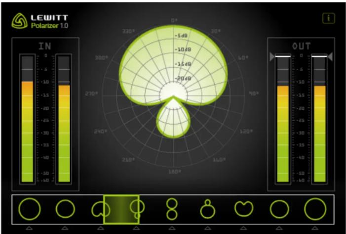
We have come up with a more convenient way to change the polar pattern. Let's not call it laziness, let's call it improved workflow. To make it easier and more fun to experiment with different polar patterns we created a plugin, the "Polarizer". It essentially does the same thing as shown in the table on the previous page, but automatically. You can even create an automation track, making the polar pattern change automatically according to your settings and track! It is compatible with PC and MAC and available as VST, AU and AAX plugin.
8.1. Installation MAC (MAC OS 10.5 and higher)
// Download the MAC plugins here.
// Unzip the file.
// Double click the Polarizer.dmg.
// You will see 3 files (.vst, .au and .aax) on the left side with the corresponding folders on the right side. Drag and drop the desired plugins into the folders. The operating system will ask you to authorise the copy process, enter your system password to proceed.
// Done!
// Plugin Locations
AAX: Macintosh HD/Library/Application Support/Avid/Audio/Plug-Ins (only Pro Tools 10.3.5 and higher is supported)
AU: Macintosh HD/Library/Audio/Plug-ins/Components
VST: Macintosh HD/Library/Audio/Plug-ins/VST
8.2. Installation Windows (works on Windows 7 and higher)
// Download the Windows plugins here.
// Unzip the file.
// You will find a new folder containing three further folders. AAX, VST32, VST64.
// Now you need to manually drag the plugins into the corresponding plugin folder.
// Plugin folder locations
AAX: C:\Program Files\Common Files\Avid\Audio\Plug-Ins
only Pro Tools 10.3.5 and higher is supported.
VST 32 bit: This location depends on the DAW of your choice. It can be a custom folder anywhere on your hard drive for some DAWs, others have specific folders. Please check out the user manual of your DAW for information where to put the plugin files.
For Cubase it's: C:\Program Files (x86)\Steinberg\VSTPlugins
VST 64 bit: This location depends on the DAW of your choice. It can be a custom folder anywhere on your hard drive for some DAWs, others have specific folders. Please check out the user manual of your DAW for information where to put the plugin files.
For Cubase it's: C:\Program Files\Steinberg\Vstplugins.
9. What to do with Dual Output Mode?
There is a million of awesome things you can do with Dual Output Mode. Let's cover at least some of them:
9.1. Change or automate the polar pattern
There are many reasons why you want to change the polar pattern after the recording session, just to name a few:
// To add or remove room sound from the recording. You could, for example, leave the vocals very dry during the verse, and then add substantial room sound for the chorus to make it sound more open. The Polarizer plugin can be automated to do this.
// Minimize bleed in a recording, by adjusting polar pattern in a multi instrument session.
// Change the sound of the recording. Different polar patterns have different characteristics and frequency responses.
// Compensate the movement of musicians dynamically - mind the acceptance angle!
9.2. Change the polar pattern and direction
// Change the polar pattern and direction (0° or 180°).
// Crossfade between different polar patterns.
// Position the microphone between two vocalists for a duet - balance them later on in the post.
// Same goes for interview or podcasting situations - balance the signal later on in the post.
// Try to use one or two LCT 640 TS as drum room mics. Use the sound from the capsule facing away from the drum kit pointing at the reflective wall. If it is too diffuse, blend in a bit of the side facing the drum kit.
9.3. Stereo with only one LCT 640 TS
Usually MS stereophony is only possible using two microphones. A cardioid, supercardioid or omni for the MID-signal which points directly at the sound source, and a figure-8 turned sideways, for the SIDE-signal. With the LCT 640 TS you can do something similar, but you only need one microphone!
Step by step instruction:
// Point the side of the microphone towards the source, using the dual output mode.
// Record a stereo track with your LCT 640 TS.
// Make two copies of the track giving you three stereo tracks in total.
// Insert the Polarizer plugin on every track.
// Set one stereo track to omni, and the other two to figure-8.
// Pan the first figure-8 track hard left and the second hard right.
// Link the channels.
// Switch the phase on one of the two figure-8 tracks.
// By changing the ratio between the omni and figure-8's you can adjust the stereo width.
9.4. Stereo recording - the easy way
// Turn the side of the microphone to the sound source.
// Put the front signal on the left channel of a stereo track and the back signal on the right channel of the stereo track.
// Change the panorama for both signals to adjust the stereo width. If the panorama is in the center, the signal is mono (front + back = omni). If the panorama sliders are hard left and hard right it has the maximum stereo effect.
10. Stereo applications with two LCT 640 TS
The LCT 640 TS is a unique microphone through and through. Its Perfect Match Technology combined with the Dual Output Mode and the Polarizer Plugin opens a whole new world of possibilities for stereo recordings.
There are two basic principles that allow us to record and more importantly hear stereophonic; we can determine the location of a sound source by differences in level and time differences. Let's briefly go over some popular stereo recording techniques.
10.1. XY and Blumlein
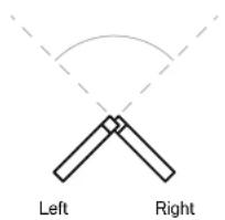
The XY stereo technique is based on level differences between 2 directional microphones. Their capsules are placed together as close as possible and one microphone points right the other one left. The opening angle is variable but usually at least 90^ . XY stereo recording techniques are excellent for locating individual sources in a recording and are mono compatible. A special XY recording technique is “Blumlein”, named after Alan Blumlein, a pioneer in stereo recording. It consists of 2 figure-8 microphones with an opening angle of 90^ . It is known for it’s very balanced and natural sound.
The polar pattern used has a big influence on the stereo image. To locate a signal 100% left or 100% right the level difference between the two signals must be 15 dB. A look at the pictures on the left illustrates what opening angles are necessary to get the widest stereo image for different polar patterns.
With the LCT 640 TS it is possible to change the polar pattern during the mixing process. This way you can adjust the stereo width by changing the polar pattern. The polar pattern also defines how much sound you capture from behind the microphone.
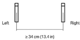
10.2. AB stereo
AB stereo uses time differences to capture a stereo recording. Two microphones, usually omni - sometimes wide cardioid or cardioid are placed in parallel to the sound source with a distance to each other of at least 34 cm. A distance of 34 cm results in a time difference of 1 ms. If the signal on the right channel arrives at your ears 1 ms earlier than the same signal on the left channel it will feel like it is only coming from the right channel. AB stereophony gives the listener a great feel of the room sound while localisation of individual signals is not as precise as XY stereophony. With the LCT 640 TS you have a great tool for AB stereophony as you can adjust how much room sound you want to have in your recording, even after the recording.
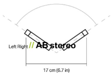
10.3. ORTF
ORTF (Office de Radiodiffusion Télévision Française) was introduced by French radio broadcasting engineers. It is a combination of level based and time based stereophony. The capsules are placed 17 cm apart with an opening angle of 110°. The result has all the qualities of both methods combined. By changing the polar pattern you can change the stereo width and also the amount of room sound.
// XY and Blumlein
// XY stereo recording
// AB stereo recording
// ORTF stereo recording
11. Perfect Match Technology
Our Perfect Match Technology is a unique approach to matching microphones for stereo and surround use. Usually a matched pair will be selected after production to have a similar sensitivity at 1kHz - this usually involves a lot of testing of each microphone after production and making pairs or groups of units with similar specs. To us this seems like an outdated approach so we made matching the microphones an integral part of the production process.
First, it is important to understand what sensitivity in a microphone means. Sensitivity determines how much voltage is output at a given sound pressure level. How sensitive a microphone is depends mostly on the size and construction of the capsule and the polarisation voltage. Externally polarized condenser capsules need to be polarized. A higher polarisation voltage will increase sensitivity. Of course there is also a limit of how much voltage you can put on the capsule before a reliable operation is not possible anymore.
We put a microcontroller into the LCT 640 TS that can control the polarisation voltage. During production we increase or decrease the polarisation voltage to achieve exactly the same sensitivity in every single LCT 640 TS ever produced.
12. Safety guidelines
// The capsule is a sensitive, high precision component. Make sure you do not drop it from great heights and avoid strong mechanical stress and force.
// To ensure high sensitivity and best sound reproduction of the microphone, avoid exposing it to moisture, dust or extreme temperatures.
// Keep this product out of the reach of children.
// Do not use force on the switch or cable of the microphone.
// When disconnecting the microphone cable, grasp the connector and do not pull the cable.
// Do not attempt to modify or fix it. Contact qualified service personnel in case any service is needed. Please do not disassemble or modify the microphone for any reasons as this will void users warranty.
// The casing of the microphone can be cleaned easily using a wet cloth, never use alcohol or another solvent for cleaning. If necessary the foam wind stopper can be washed with soap water. Please wait till it is dry before using it again.
// Please also refer to the owner's manual of the component to be connected to the microphone.
13. Regulatory information
Changes or modifications not expressly approved by the party responsible for compliance could void the user's authority to operate the equipment.
This device complies with part 15 of the FCC Rules. Operation is subject to the following two conditions: (1) This device may not cause harmful interference, and (2) this device must accept any interference received, including interference that may cause undesired operation.
Declaration of conformity can be requested at info@lewitt-audio.com.
Manufacturer Details
LEWITT GmbH
Burggasse 79
1070 Vienna, Austria

DI Roman Perschon
CEO LEWITT GmbH
