
VT-6056-4 - Household Fan V-TAC - Free user manual and instructions
Find the device manual for free VT-6056-4 V-TAC in PDF.


| Product Type | Decorative Ceiling Fan |
| Model | VT-6056-4 |
| Brand | V-TAC |
| Blade Span | 52 inches (132 cm) |
| Number of Blades | 4 |
| Blade Material | MDF with reversible dual-color finish |
| Motor Specifications | 153 x 11 mm, 2.3 kg, 190 ± 10 RPM |
| Blade Angle | 12° |
| Speed Settings | 3 speeds (High, Medium, Low) via pull chain |
| Direction Control | Forward (downward airflow) and Reverse (upward airflow) via slide switch |
| Light Kit | 4 x E27 sockets, 4 glass shades, bulbs not included |
| Power Supply | 220 V, 50 Hz, 60 W (motor only) |
| Net Weight | 3.8 kg |
| Gross Weight | 4.5 kg |
| Mounting Type | Standard (downrod) or flush mount for low ceilings |
| Minimum Ceiling Height | 7 feet (2.13 m) from blade to floor |
| Minimum Wall Clearance | 20 inches (50.8 cm) from blade tip |
| Safety Suspension | Supports up to 15.9 kg (35 lbs), use only approved outlet box |
| Warranty | 2 years from date of purchase (manufacturing defects only) |
| WEEE Number | 80133970 |
| Recommended Usage | 10-12 hours daily; 24-hour operation voids warranty |
| Cleaning Instructions | Use damp soft cloth for housing; dry cloth or duster for blades, no cleaning agents |
| Lubrication | Not required; sealed ball bearings |
Frequently Asked Questions - VT-6056-4 V-TAC
User questions about VT-6056-4 V-TAC
0 question about this device. Answer the ones you know or ask your own.
Ask a new question about this device
Download the instructions for your Household Fan in PDF format for free! Find your manual VT-6056-4 - V-TAC and take your electronic device back in hand. On this page are published all the documents necessary for the use of your device. VT-6056-4 by V-TAC.
USER MANUAL VT-6056-4 V-TAC
- Before beginning installation of your ceiling fans, read and follow these safety precautions. If you are not familiar with national and local electrical codes and basic electrical wiring procedures, we recommend that you have a qualified electrician to install your new ceiling fan.
- Before you begin. Turn off the electricity. Determine which circuit your new fan will be using and remove the fuse or turn off the circuit breaker at the main electrical panel.
- Make sure that all wiring conforms to national and local electrical codes. If you are in question, obtain a copy of the codes and wire the fan accordingly. Never leave bare wires uncovered (wire connection), use wire nuts to cap all connections. Plastic electrical tape is not recommended.
- When working with electricity, never take short cuts. Follow the code in every aspect. Basic requirements for a ceiling fan installed with lights are match it with specifications, on a grounded circuit with a 15 amp breaker or fuse. Make sure that your electrical system and choice of location meet these requirements.
- If the location where you plan to install your fan does not already have an electrical outlet, hire a licensed electrician to run the wiring and install an outlet box designed for ceiling fans or heavy fixtures. The outlet box should be able to support a minimum moving weight of 22kg and marked "Acceptable for Fan Support" (Plastic outlet boxes are not recommended for ceiling fan installation).
- If you plan to use an existing electrical location, check to make sure that the outlet box is not PLASTIC, that is securely attached and able to support at least 22kg of moving weight and marked "Acceptable for Fan Support".
- The location you choose should have a minimum clearance of 20 inches from any wall to the blade tip at any point in its rotation and a minimum of 7 feet from blade level to floor and 10 inches from the blades.
- This ceiling fan was not designed for installation in any location where it might be exposed to moisture or high humidity. Installation in this type of location could be UNSAFE, will most likely damage the fan and its finish and will void your warranty
- Every effort has been made to provide you with proper instructions for the safe installation of this ceiling fan. You could however, encounter situations or problems not covered in this manual. Should this occur, please refer to a do-it-yourself wirings handbook or hire a qualified electrician to install your fan.
- Never attach the blades to your ceiling fan before the fan body is properly mounted on the ceiling.
- Lubrication of your new ceiling fan is not necessary. The ball bearings have been adequately charged with grease and permanently sealed at the factory so that, under normal conditions further attention is not necessary.
- To reduce the risk of fire, electrical shock, or personal injury, mount this fan to an outlet box marked "Acceptable for Fan Support of 15.9 KG (35lbs)" or less and use Mounting Screws provided with the outlet box.
CAUTION: Install the primary mounting means and use only the hardware provided with the fan. - To reduce the risk of personal injury take care not to bend the blade brackets when installing the brackets, balancing the blades or clearing the fan. Be careful not to insert foreign objects in between rotating fan blades.
-
To reduce the risk of fire or electrical shock, do not use this fan with any solid-state speed control device.
-
The important safeguards and instructions appearing in the manual are not meant to cover all possible conditions and situations that may occur. Please ensure to take caution and careful attention to detail are factors which cannot be built into this product. These factors must be supplied by the person or person installing, caring for and operating the unit.
• These instructions are designed for a number of similar but different ceiling fans. As you proceed, some steps may or may not apply to the fan purchased. Compare each step or optional procedure to your fan and proceed accordingly. - This fan is shipped with 1 down rod. 4" or regular ceiling application.
- The appliance is not intended to be used by children under the age of 8. It can be used by children over the age of 8, as long as they are given continuous supervision.
- This appliance is not intended to be used by persons with reduced physical, sensory, or mental capabilities, or lack of experience or knowledge, unless they have been given supervision or instruction concerning the use of the appliance in a safe way by a person responsible for their safety, and understand the hazards involved.
- Supervise young children to make sure that they do not play with the appliance. Close supervision is necessary when the appliance is being used by or near children.
- Keep the appliance and its cord out of reach of children under the age of 8.
- Do not try to repair the appliance by yourself. Contact the official Technical Support Service for advice.
- Cleaning and maintenance must be carried out according to this instruction manual to make sure the appliance functions properly. Turn off and unplug the appliance before cleaning it.
-
This appliance can be used by children aged from 8 years and above and persons with reduced physical, sensory or mental capabilities or lack of experience and knowledge if they have been given supervision or instruction concerning use of the appliance in a safe way and understand the hazards involved. Children shall not play with the appliance. Cleaning and user maintenance shall not be made by children without supervision.
-
If unusual oscillating movement is observed, immediately stop using the ceiling fan and contact the manufacturer, its service agent or suitably qualified persons.
- The replacement of parts of the safety suspension system device shall be performed by the manufacturer, its service agent or suitably qualified persons.
- The mounting of the suspension system shall be performed by the manufacturer, its service agent or suitably qualified person.
- Please make sure to turn off the power before starting the installation.
- Proper grounding should be ensured throughout the installation.
• Installation should only be done by a certified electrician.
This marking indicates that this product should not be disposed of with other household wastes.

Caution, risk of electric shock.
INTRODUCTION & WARRANTY
Thank you for selecting and buying V-TAC product. V-TAC will serve you the best. Please read these instructions carefully before starting the installation and keep this manual handy for future reference. If you have any another query, please contact our dealer or local vendor from whom you have purchased the product. They are trained and ready to serve you at the best. The warranty is valid for 2 years from the date of purchase. The warranty does not apply to damage caused by incorrect installation or abnormal wear and tear. The company gives no warranty against damage to any surface due to incorrect removal and installation of the product. The products are suitable for 10-12 Hours Daily operation. Usage of product for 24 Hours a day would void the warranty. This product is warranted for manufacturing defects only.
WEEE Number: 80133970
INSTRUCTION MANUAL
DECORATIVE CEILING FANS (VT-6056-4)

natural_image
Modern double-decker ceiling fan with four blades and a decorative cloud (no text or symbols visible)TECHNICAL DATA
1) 52" (132CM) Decorative ceiling fan
2) With forward and reverse function
3) 4 MDF blades with cane and double color
4) Powerful Motor:153 × 11mm, 2.3kg
5) Revolutions per minute:190±10 RPM
6) Blade angle 12°
7) 3 speeds and light pull chain
8) 4xE27 light kit (light source NOT included)
9) 4 glass shade
10) Power:220V,50HZ,60W (Power of the motor)
11) G.W.:4.5KG / N.W.:3.8KG
MULTI-LANGUAGE MANUAL QR CODE

Please scan the QR code to access the manual in multiple languages.
STEP 1. ATTACH THE MOUNTING BRACKET
- Loosen the 2 canopy mounting screws on the downside face or the mounting bracket. Back them out about half way (see figure 1).
- This will allow for easier installation of the ceiling canopy later.

Install the mounting bracket to the electrical junction box in the ceiling. Using two (2) machine screws, two (2) washers, and two (2) lock washers (see figure 2).
Note: You may need a longer down rod to maintain proper blade clearance when installing on a steep, sloped ceiling (see figure 3).
The mounting bracket has slotted holes to enable it to move sideways for proper alignment. Make sure the mounting bracket is centered over the electrical junction box and that is securely attached (see figure 4).

natural_image
Technical line drawing of a mechanical assembly with no visible text or symbolsJUNCTION BOX
FIG. 2


natural_image
Simple line drawing of a hand holding a flag with a grid pattern, no text or symbols presentJUNCTION BOX
HANGER OPENING
MUST BE FACING
UP-SIDE
FIG. 3
Pull the electric wires in the junction box down through the mounting bracket then bend them up and back out of the way. Place the black wire to one side and the white and ground wire to the other side (see figure 5). The wires should be off to the side and up against the ceiling. This will leave the mounting bracket open and ready to receive the ceiling fan.
STEP 2. ATTACHING THE SUPPORT ASSEMBLY
- If you are using an extended support rod, (longer than the one supplied with your fan) remove the halt ball from support assembly and attach it to the extended support rod at this point. Make sure to retighten the set screw and insert the safety pin.
- Back off (loosen) the set screws (2) in the support rod coupler until the inside of the channel is clear of the screw tip.
- Remove and save the safety pin on the end of the support rod assembly.
- Place the ceiling canopy face down (small end) over the support rod coupler on the motor housing.
- Feed the electrical wire from the fan housing through the support rod.

natural_image
Technical line drawing of a mechanical assembly with wires and components (no text or symbols)
- Thread the support rod into the support rod coupler until the safety pin can be inserted through the hole in both the rod and coupler.
- Insert the safety screw through the hole in the support rod coupler and support rod then attach the washer and retaining clip on the other side.
- Tighten both set screws and safety screw on the support road coupler.
- This fan is designed to be mounted as a flush mount (for lower ceiling heights), or suspended.
FLUSHMOUNT (SEE FIGURE 7)
Loosen the set screws (2) in the support rod coupler located on top center of the motor housing until the inside channel is clear.
Remove and save the safety screw from the coupler.
Place the ceiling canopy on top of the motor housing and secure with the three mounting screws.

STEP 3. HANGING THE FAN BODY
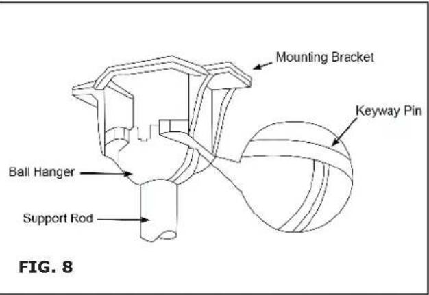
- Notice the half ball on the end of the support rod is grooved down one side (see figure 8). This Keyway fits over the small keyway pin on the inside of the mounting bracket and keeps the ceiling fan from spinning on the mounting bracket.
- Using your step ladder, lift the fan and place the half ball in the center of the mounting bracket with the keyway pin inserted into the keyway on the ball. Turn the fan left and right slightly to make sure it is seated on the bracket with the keyway (see fig 9).
- Trim the lead wires, leaving about six inches of each wire extending from the support rod (see fig 10)


MAKING THE ELECTRICAL CONNECTIONS
- To operate your ceiling fan with the pull chain (sand switches mounted on your fan, follow the instruction below (see figure 11).
- If you require or would like to use a different method of controlling your fan refer to the Optical Electrical wiring Procedures.
- Attach the GREEN/YELLOW wire (connected to the half of the ball) to the GROUND wire in the junction box. The GROUND wire is usually a bare copper wire without plastic insulation. It could also be covered in green plastic insulation.
- Attach the BLACK wire & BLUE wire from the ceiling fan to the BLACK wire in the junction box.
- Attach the WHITE wire from the ceiling fan to the WHITE wire in the junction box.
• Each of the above connections should be made as tight as possible using the proper size plastic wire nuts. Plastic electrical tape is not recommended for these connections. - Fold the connected wire(see figure 12) and push them inside the electrical junction box with the BLACK and BLUE wires to one side and the WHITE and GREEN/YELLOW to the other side. Make sure the wire nuts do not come loose during this operation.


STEP 4. INSTALL THE CEILING FAN
- If you are using the Flush Mount system skip this step.
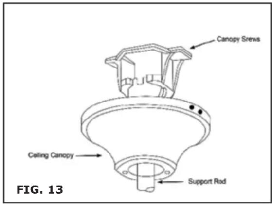
- Slide the ceiling canopy up into place over the ceiling mounting bracket (see figure 13). The two screws on the side of the mounting bracket face should slip through the key hole slots in the canopy then tighten both screws.
- Depending on how deep the electrical junction box was installed in the ceiling you might have a slight gap between the ceiling canopy and ceiling. Junction boxes are commonly installed at different depths in the ceiling, so we have designed the mounting bracket and ceiling canopy to allow for this.
STEP 5. BLADE AND BLADE ARM ASSEMBLY
- This fan is supplied with a reversible blade finish. Choose the blade finish that you prefer and attach as follow:
- Attach each fan blade to a blade arm with three washer head screws and three screw pads (see figure 14). Each screw is passed through the screw pad, then the blade and screwed into the blade arm.
- Screws should be tightened until the screw pads are compressed. Hold the blade arm decorative side down and place the blade on top with your choice of finish facing down.

natural_image
Mechanical assembly diagram showing a bracket with mounting holes and a separate piece with a wrench, labeled as FIG. 14 (no text or symbols on the diagram itself)STEP 6. BLADE ASSEMBLY INSTALLATION
- Remove the large screws in the face of the motor.
- Discard any rubber blocks attached to these screws.
- The rubber blocks are installed at the factory to stabilize the motor during shipment. Select the correct mounting pattern and attach each blade to the motor face using pre-installed screws (see figure 15). Take care not to bend the blade arms during installation. This will cause your fan to wobble while running. Try mounting the blades on the opposite side of the motor face. This will help keep the fan more level during blade installation.

STEP 7. INSTALLATION OF LIGHT FIXTURE
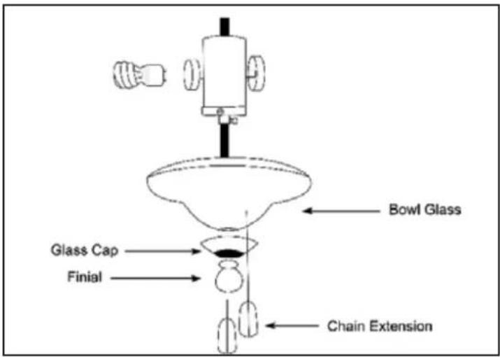
Depending on which model of Heritage Square you are installing, you will either have the 4 light Turtle Cluster (see figure 16 & 17) or the Bowl Light (see figure 18 & 19). Please follow instructions under the correct light fixture.
TURTLE CLUSTER:
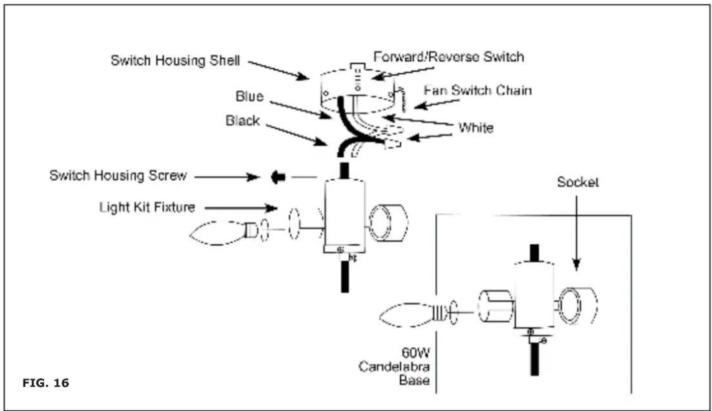
- Connect white wire to white wire and blue wire to black wire. Secure with wire nuts.
- Remove switch housing screws. Press fixture up into switch housing shell, aligning screw holes. Insert (3) screws and tighten firmly (see figure 16).
- Slide glass shades over sockets and tighten set screw until snug to glass. Install 60 watt bulb (see figure 17).
flowchart
graph TD
    A["Switch Housing Shell"] --> B["Forward/Reverse Switch"]
    C["Blue"] --> B
    D["Black"] --> B
    E["Fan Switch Chain"] --> B
    F["White"] --> B
    G["Switch Housing Screw"] --> H["Light Kit Fixture"]
    H --> I["60W Candelabra Base"]
    J["Socket"] --> K["60W Candelabra Base"]
    style A fill:#f9f,stroke:#333
    style C fill:#f9f,stroke:#333
    style D fill:#f9f,stroke:#333
    style E fill:#f9f,stroke:#333
    style F fill:#f9f,stroke:#333
    style G fill:#f9f,stroke:#333
    style H fill:#f9f,stroke:#333
    style I fill:#f9f,stroke:#333
    style J fill:#f9f,stroke:#333
    style K fill:#f9f,stroke:#333
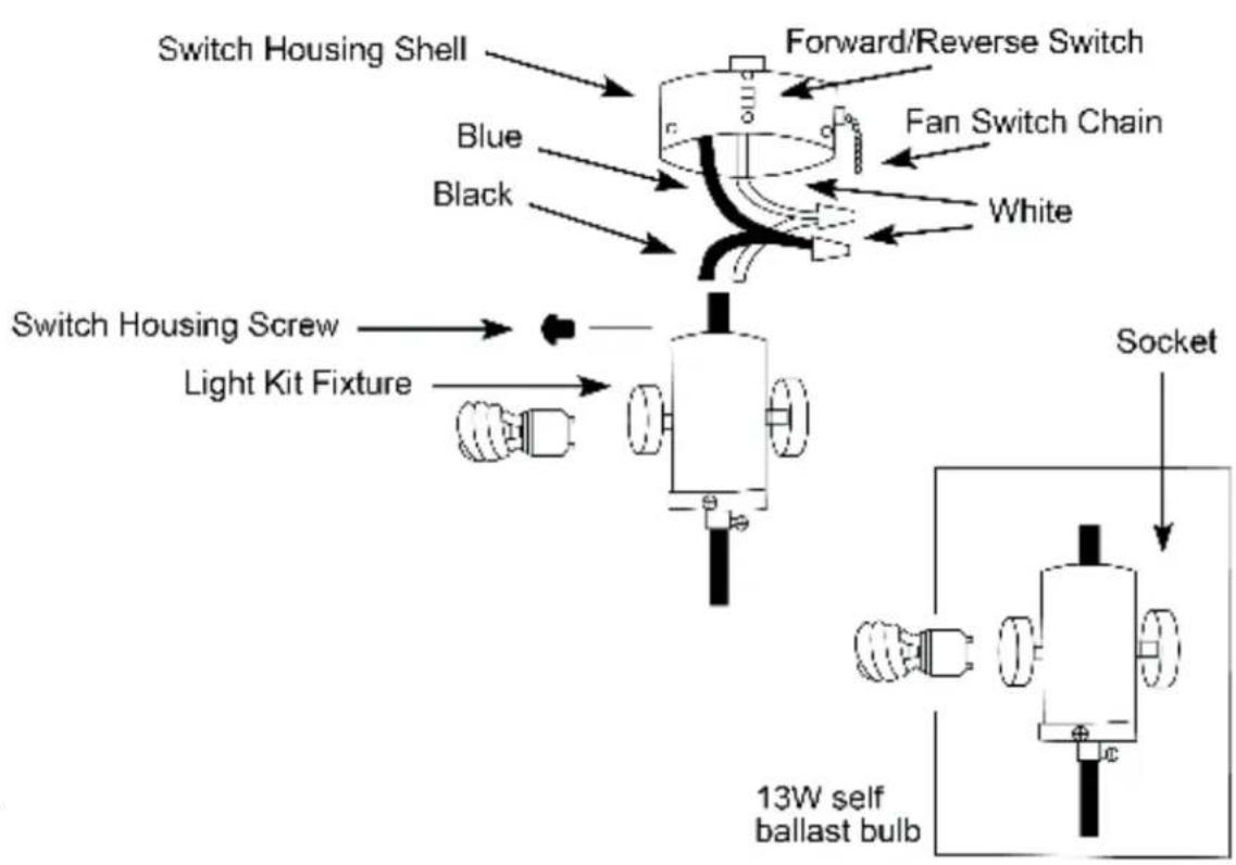
FIG. 17

BOWL GLASS:
- Connect white wire to white wire and blue wire to black wire. Secure with wire nuts.
- Remove switch housing screws. Press light kit fixture up into switch housing shell, aligning screw holes. Insert (3) screws and tighten firmly (see figure 18 and 19).
• Install (2) 60 Watt Candelabra Base bulbs or (2) GU24 Base self ballast bulbs. Side bowl glass over the threaded nipple, followed by the glass cap and then finial. Twist finial clock-wise until snug. - Lower chains through hole in bowl glass and glass cap. Attach chain extensions (see figure 18 and 19).
STEP 8. FINAL CHECKS
- Check that all safety pins, set screws and connections are properly in place and tight.
- Check blade clearance and rotation.
- Attach the decorative pull chain tassel(s) to the switch housing.
- Located on the side of the switch housing is a slide switch. This switch controls the direction of blade rotation. The UP position sets the blade in reverse rotation (air moves UP). The DOWN position sets the blades in forward rotation (air moves DOWN). Make sure this switch is all the way UP or DOWN, your fan will not run if it is in the middle.
- Illustrations in figures 20 and 21 show optional wiring diagrams that you can use.

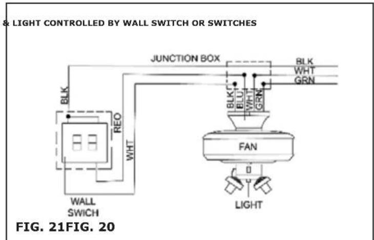
ONLY USE AN OPTIONAL WALL SWITCH THAT HAS BEEN DESIGNED FOR THE USE WITH CEILING FAN
- Your dealer carries a number of different types of wall switches that have been designed and tested for use with our products. To obtain the best performance electrical components should be matched for output, for that reason we only recommend the use of wall switch(s) that your dealer provides.
- If you elect to control the motor of your ceiling fan from a wall switch, remember that the wall switch will only turn your fan on and off. The speeds can be adjusted at the fan.
- If you elect to control the speeds of your ceiling fan from a wall switch. YOU MUST set the speed switch on the ceiling fan to HIGH speed and leave it in that setting.
- Your new ceiling fan is now ready to use. Reset your circuit breaker and restore the power to the circuit. See the Operation Instruction below to review the function of each control on your fan.
OPERATION INSTRUCTIONS
- The pull chain located on the switch housing controls the speed of your fan. When the fan is off, pull the chain once for HIGH speed, twice for MEDIUM speed, three times for LOW speed and fourth time to turn it off again.
- The slide switch located on the switch housing controls the direction of blade rotation. The UP position sets the blade in reverse rotation (air moves UP). The DOWN position sets the blades in forward rotation (air moves DOWN).
MAINTENANCE
- Your fan requires very little maintenance. Cleaning of the housing should be done with a damp soft cloth, NO CLEANING AGENTS are to be used for cleaning the blades, use a duster or dry cloth because any moisture could cause the blade to warp.


In case of any query/issue with the product, please reach out to us at: support@v-tac.eu For More products range, inquiry please contact our distributor or nearest dealers. V-TAC EUROPE LTD. Bulgaria, Plovdiv 4000, bul.L.Karavelow 9B
- INTRODUCTION & WARRANTY
- INSTRUCTION MANUAL
- TECHNICAL DATA
- MULTI-LANGUAGE MANUAL QR CODE
- STEP 1. ATTACH THE MOUNTING BRACKET
- STEP 2. ATTACHING THE SUPPORT ASSEMBLY
- FLUSHMOUNT (SEE FIGURE 7)
- STEP 3. HANGING THE FAN BODY
- MAKING THE ELECTRICAL CONNECTIONS
- STEP 4. INSTALL THE CEILING FAN
- STEP 5. BLADE AND BLADE ARM ASSEMBLY
- STEP 6. BLADE ASSEMBLY INSTALLATION
- STEP 7. INSTALLATION OF LIGHT FIXTURE
- TURTLE CLUSTER:
- BOWL GLASS:
- STEP 8. FINAL CHECKS
- OPERATION INSTRUCTIONS
- MAINTENANCE
Brand : V-TAC
Model : VT-6056-4
Category : Household Fan