
SWB6552 - Screen VIEWSONIC - Free user manual and instructions
Find the device manual for free SWB6552 VIEWSONIC in PDF.


| Product Type | Monitor |
| Brand | Viewsonic |
| Model | SWB6552 |
| Screen Size | 24 inches |
| Resolution | 1920 x 1080 (Full HD) |
| Panel Type | IPS |
| Refresh Rate | 75 Hz |
| Response Time | 5 ms |
| Connectivity | HDMI, VGA, DisplayPort |
| Built-in Speakers | 2 x 2W |
| VESA Mount | 100 x 100 mm |
| Dimensions (with stand) | 540 x 410 x 200 mm |
| Weight (with stand) | 4.5 kg |
| Power Consumption | 35 W (typical) |
| Special Features | Flicker-Free, Blue Light Filter, Eco Mode |
| Cleaning Instructions | Use a soft, dry cloth to clean the screen. Avoid solvents. |
| Safety Precautions | Do not open the back cover. Use only the provided power adapter. |
| Spare Parts | Power cable, stand, HDMI cable (included) |
Frequently Asked Questions - SWB6552 VIEWSONIC
User questions about SWB6552 VIEWSONIC
0 question about this device. Answer the ones you know or ask your own.
Ask a new question about this device
Download the instructions for your Screen in PDF format for free! Find your manual SWB6552 - VIEWSONIC and take your electronic device back in hand. On this page are published all the documents necessary for the use of your device. SWB6552 by VIEWSONIC.
USER MANUAL SWB6552 VIEWSONIC
IMPORTANT: Please read this User Guide to obtain important information on installing and using your product in a safe manner, as well as registering your product for future service. Warranty information contained in this User Guide will describe your limited coverage from ViewSonic Corporation, which is also found on our web site at http://www.viewsonic.com in English, or in specific languages using the Regional selection box in the upper right corner of our website. "Antes de operar su equipo lea cu idadosamente las instrucciones en este manual"
Model No. VS15421/VS15432/VS15633/VS15420
Compliance Information
NOTE: This section addresses all connected requirements and statements regarding regulations. Confirmed corresponding applications shall refer to nameplate labels and relevant markings on unit.
FCC Compliance Statement
This device complies with part 15 of FCC Rules. Operation is subject to the following two conditions: (1) this device may not cause harmful interference, and (2) this device must accept any interference received, including interference that may cause undesired operation.
This equipment has been tested and found to comply with the limits for a Class B digital device, pursuant to part 15 of the FCC Rules. These limits are designed to provide reasonable protection against harmful interference in a residential installation. This equipment generates, uses, and can radiate radio frequency energy, and if not installed and used in accordance with the instructions, may cause harmful interference to radio communications. However, there is no guarantee that interference will not occur in a particular installation. If this equipment does cause harmful interference to radio or television reception, which can be determined by turning the equipment off and on, the user is encouraged to try to correct the interference by one or more of the following measures:
- Reorient or relocate the receiving antenna.
- Increase the separation between the equipment and receiver.
- Connect the equipment into an outlet on a circuit different from that to which the receiver is connected.
- Consult the dealer or an experienced radio/TV technician for help.
Warning: You are cautioned that changes or modifications not expressly approved by the party responsible for compliance could void your authority to operate the equipment.
Industry Canada Statement
CAN ICES-3 (B)/NMB-3(B)
CE Conformity for European Countries

The device complies with the EMC Directive 2004/108/EC and Low Voltage Directive 2006/95/EC.
Following information is only for EU-member states:
The mark shown to the right is in compliance with the Waste Electrical and Electronic Equipment Directive 2002/96/EC (WEEE). The mark indicates the requirement NOT to dispose the equipment as unsorted municipal waste, but use the return and collection systems according to local law.

Declaration of RoHS2 Compliance
This product has been designed and manufactured in compliance with Directive 2011/65/EU of the European Parliament and the Council on restriction of the use of certain hazardous substances in electrical and electronic equipment (RoHS2 Directive) and is deemed to comply with the maximum concentration values issued by the European Technical Adaptation Committee (TAC) as shown below:
| Substance | Proposed Maximum Concentration | Actual Concentration |
| Lead (Pb) 0.1% < 0.1% | ||
| Mercury (Hg) 0.1% < 0.1% | ||
| Cadmium (Cd) 0.01% < 0.01% | ||
| Hexavalent Chromium ( Cr^6+ ) 0.1% < 0.1% | ||
| Polybrominated biphenyls (PBB) | 0.1% < 0.1% | |
| Polybrominated diphenyl ethers (PBDE) | 0.1% < 0.1% |
Certain components of products as stated above are exempted under the Annex III of the RoHS2 Directives as noted below:
Examples of exempted components are:
- Mercury in cold cathode fluorescent lamps and external electrode fluorescent lamps (CCFL and EEFL) for special purposes not exceeding (per lamp):
(1) Short length ( ≤ 500 mm): maximum 3.5 mg per lamp.
(2) Medium length (>500 mm and ≤ 1,500 mm): maximum 5 mg per lamp.
(3) Long length (>1,500 mm): maximum 13 mg per lamp.
-
Lead in glass of cathode ray tubes.
-
Lead in glass of fluorescent tubes not exceeding 0.2% by weight.
-
Lead as an alloying element in aluminium containing up to 0.4% lead by weight.
-
Copper alloy containing up to 4% lead by weight.
-
Lead in high melting temperature type solders (i.e. lead-based alloys containing 85% by weight or more lead).
-
Electrical and electronic components containing lead in a glass or ceramic other than dielectric ceramic in capacitors, e.g. piezoelectronic devices, or in a glass or ceramic matrix compound.
Cautions and Warnings
- Read these instructions completely before using the equipment.
- Keep these instructions in a safe place.
- Heed all warnings and follow all instructions.
- Always handle the LCD display with care when moving it.
- Never remove the rear cover. This LCD display contains high-voltage parts. You may be seriously injured if you touch them.
- Do not use this equipment near water. Warning: To reduce the risk of fire or electric shock, do not expose this apparatus to rain or moisture.
- Avoid exposing the LCD display to direct sunlight or another heat source. Orient the LCD display away from direct sunlight to reduce glare.
- Clean with a soft, dry cloth. If further cleaning is required, see the "Care and Maintenance" section in this guide for further instructions.
- Avoid touching the screen. Skin oils are difficult to remove.
- Do not rub or apply pressure to the LCD panel, as it may permanently damage the screen.
- Do not block any ventilation openings. Install the equipment in accordance with the manufacturer's instructions.
- Do not install near any heat sources such as radiators, heat registers, stoves, or other devices (including amplifiers) that produce heat.
- Place the LCD display in a well ventilated area. Do not place anything on the LCD display that prevents heat dissipation.
- Do not place heavy objects on the LCD display, video cable, or power cord.
- If smoke, an abnormal noise, or a strange odor is present, immediately switch the LCD display off and call your dealer or ViewSonic. It is dangerous to continue using the LCD display.
- Do not attempt to circumvent the safety provisions of the polarized or grounding-type plug. A polarized plug has two blades with one wider than the other. A grounding type plug has two blades and a third grounding prong. The wide blade and the third prong are provided for your safety. If the plug does not fit into your outlet, consult an electrician for replacement of the outlet.
- Protect the power cord from being tread upon or pinched, particularly at the plug, and the point where if emerges from the equipment. Be sure that the power outlet is located near the equipment so that it is easily accessible.
- Only use attachments/accessories specified by the manufacturer.
(Continued on next page)
- Use only with the cart, stand, tripod, bracket, or table specified by the manufacturer, or sold with the equipment. When a cart is used, use caution when moving the cart/equipment combination to avoid injury from tipping over.

-
Unplug this equipment when it will be unused for long periods of time.
-
Refer all servicing to qualified service personnel. Service is required when the unit has been damaged in any way, such as: if the power-supply cord or plug is damaged, if liquid is spilled onto or objects fall into the unit, if the unit is exposed to rain or moisture, or if the unit does not operate normally or has been dropped.
Contents
Compliance Information
FCC Compliance Statement......i
Industry Canada Statement......i
CE Conformity for European Countries......i
Declaration of RoHS2 Compliance......ii
Cautions and Warnings....iii
Copyright Information
Product Registration....2
For Your Records....2
1. Getting Started
1.1 Package Contents....3
1.2 Wall Mount Kit Specifications (VESA)....4
2. Smart Whiteboard/LCD Display Features
2.1 Control Panel Overview....5
2.2 Terminal Interface Overview 7
2.3 Remote Control Overview 9
2.4 Inserting Remote Control Batteries 11
2.5 Remote Control Receiver Range 12
3. Setting Up Your Display
3.1 Connecting an External PC 13
3.2 RS232 Connections 15
3.3 Connecting USB Peripherals....16
3.4 AV IN Connections....18
3.5 S-Video Connections....19
3.6 YPbPr Connections....20
3.7 HDMI Connections 21
3.8 Microphone Connections....22
3.9 Coaxial Connections 23
3.10 VGA Connections....24
3.11 AV OUT Connections 26
4. Basic Display Operations
5. OSD Menu Operation
5.1 Input Source 28
5.2 Screen Menu 29
5.3 Picture Menu 30
5.4 Sound Menu....31
5.5 Time Menu 32
5.6 Lock Menu....33
5.7 Setup Menu 34
6. Trouble Shooting
7. Care and Maintenance
8. Display Modes
8.1 YPbPr Mode 38
8.2 VGA Mode 38
8.3 HDMI Mode 39
9. Specifications
10. RS-232 Protocol
10.1 Introduction....41
10.2 Description 41
10.2.1 Hardware specification....41
10.2.2 Communication Setting 42
10.2.3 Command Message Reference....42
10.3 Protocol 42
10.3.1 Set-Function Listing....42
10.3.2 Get-Function Listing 48
10.3.3 Remote Control Pass-through mode....51
Other Information
Customer Support 53
Limited Warranty 54
Copyright Information
Copyright © ViewSonic® Corporation, 2013. All rights reserved.
Macintosh and Power Macintosh are registered trademarks of Apple Inc.
Microsoft, Windows, and the Windows logo are registered trademarks of Microsoft Corporation in the United States and other countries.
ViewSonic, the three birds logo, OnView, ViewMatch, and ViewMeter are registered trademarks of ViewSonic Corporation.
VESA is a registered trademark of the Video Electronics Standards Association. DPMS, DisplayPort, and DDC are trademarks of VESA.
SRS(●) is a trademark of SRS Labs, Inc.
Premium Sound technology is incorporated under license from SRS Labs, Inc.
ENERGY STAR ^® is a registered trademark of the U.S. Environmental Protection Agency (EPA).
As an ENERGY STAR ^® partner, ViewSonic Corporation has determined that this product meets the ENERGY STAR ^® guidelines for energy efficiency.
Disclaimer: ViewSonic Corporation shall not be liable for technical or editorial errors or omissions contained herein; nor for incidental or consequential damages resulting from furnishing this material, or the performance or use of this product.
In the interest of continuing product improvement, ViewSonic Corporation reserves the right to change product specifications without notice. Information in this document may change without notice.
No part of this document may be copied, reproduced, or transmitted by any means, for any purpose without prior written permission from ViewSonic Corporation.
Product Registration
To fulfill possible future product needs, and to receive additional product information as it becomes available, please visit your region section on ViewSonic's website to register your product online.
The ViewSonic CD also provides an opportunity for you to print the product registration form. Upon completion, please mail or fax to a respective ViewSonic office. To find your registration form, use the directory “:\CD\Registration”. Registering your product will best prepare you for future customer service needs.
Please print this user guide and fill the information in the "For Your Records" section. Your LCD displays serial number is located on the rear side of the display.
For additional information, please see the "Customer Support" section in this guide.
| For Your Records | |
| Product Name: | SWB5501/SWB6552/SWB7051/SWB8451ViewSonic Smart White BoardCDE5501/CDE6552/CDE7051/CDE8451ViewSonic LCD Display |
| Model Number: | VS15421/VS15432/VS15633/VS15420 |
| Document Number: | SWB5501/SWB6552/SWB7051/SWB8451/CDE5501/CDE6552/CDE7051/CDE8451_UG_ENGRev. 1C 10-09-13 |
| Serial Number: | |
| Purchase Date: |
Product disposal at end of product life
ViewSonic respects the environment and is committed to working and living green. Thank you for being part of Smarter, Greener Computing.
Please visit ViewSonic website to learn more.
USA & Canada: http://www.viewsonic.com/company/green/recycle-program/
Europe: http://www.viewsoniceurope.com/uk/support/recycling-information/
Taiwan: http://recycle.epa.gov.tw/recycle/index2.aspx
1. Getting Started
Congratulations on your purchase of a ViewSonic® Smart Whiteboard/LCD display.
Important! Save the original box and all packing material for future shipping needs.
Note: The word "Windows" in this user guide refers to Microsoft Windows operating system.
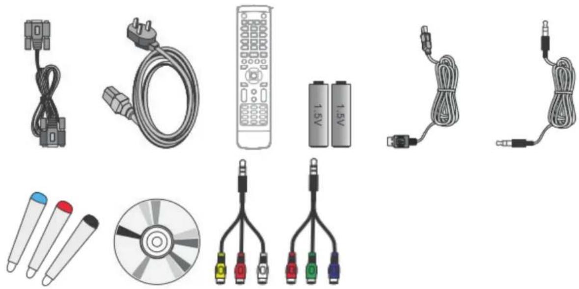
1.1 Package Contents
- Power cable
- VGA cable
- Remote control
- AAA battery x 2
- USB cable
- Audio cable
- Stylus pen x 3
- AV cable (for SWB6552/SWB7051/SWB8451/CDE6552/CDE7051/CDE8451 models only)
- YPbPr cable (for SWB6552/SWB7051/SWB8451/CDE6552/CDE7051/CDE8451 models only)
• Wall mount installation guide - User manual CD wizard
- User Guide
-ViewBoard software - User Guide
- ViewBoard software
natural_image
Collection of electronic devices and cables including a remote control, CD, and various connectors (no text or labels visible)1.2 Wall Mount Kit Specifications (VESA)
Please follow the instructions in the wall mount installation guide to install your wall mount or mobile mount bracket. If attaching to other building materials, please contact your nearest dealer.
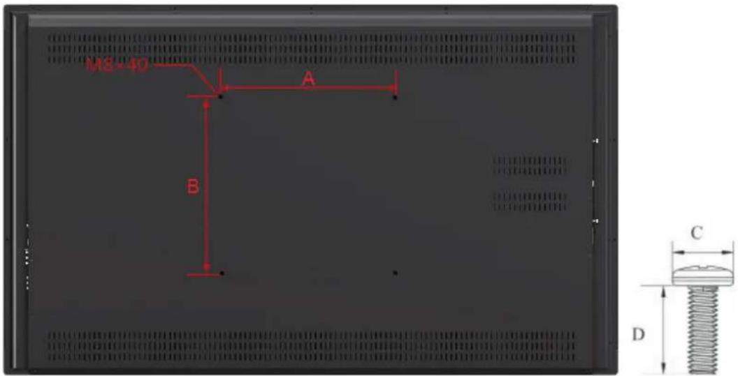
| inch VESA | Spec. (A x B) Standard | Screw (C x D) Quantity | |
| 55 400 x 40 | 0 mm M8 x L40 4 | ||
| 65 600 x 40 | 0 mm M8 x L40 4 | ||
| 70 600 x 60 | 0 mm M8 x L40 4 | ||
| 84 600 x 60 | 0 mm M8 x L40 8 |
- ViewSonic provides the standard dimensions for wall mount kits as shown in the table above.
• To find the perfect mount, please browse www.viewsonic.com or call our service team: United States 1-800-688-6688, Canada 1-866-463-4775. - When purchasing our wall mount kit, a detailed install manual and all parts necessary for assembly are provided.
- Do not use the screws that longer than the standard dimension, as they may cause damage to the inside of the LCD display set.
2. Smart Whiteboard/LCD Display Features
This section introduces you to the features of your Smart Whiteboard/LCD Display.
Note: The features or applications described in this User's manual may vary depending on the device model purchased.
2.1 Control Panel Overview
SWB5501/CDE5501 Control Panel:
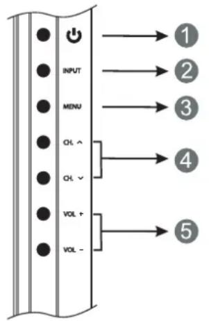
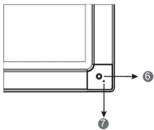
| Item Description | |
| 1 ⏻ | Power On/Off |
| 2 INPUT | Switch between different sources |
| 3 MENU | OSD Menu On/Off |
| 4 CH. | Move upward/downward to scroll through menu options. |
| 5 VOL+/- | Increase or decrease volume |
| 6 RC Receiver | Receives signals from the remote control |
| 7 Power Indicator | Indicates power status (On/Off) |
SWB6552/SWB7051/SWB8451/CDE6552/CDE7051/CDE8451 Control Panel:
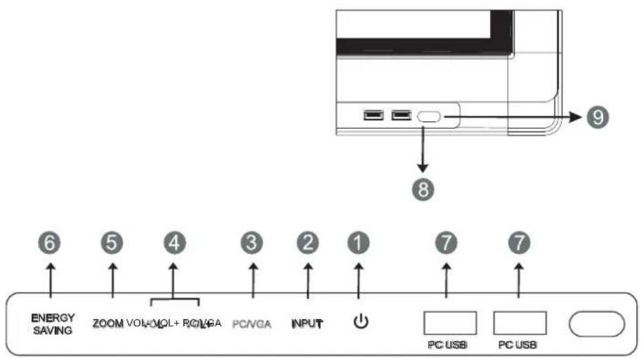
| Item Description | |
| 1 ⏻ | Power On / Off switch |
| 2 INPUT Switch to different source | |
| 3 PC/VGA Switch between PC and VGA sources | |
| 4 VOL+/- Increase or decrease volume | |
| 5 ZOOM Adjust screen ratio | |
| 6 ENERGY SAVING Energy-saving mode | |
| 7 PC USB Internal PC USB port | |
| 8 RC Receiver Receives signals from the remote control | |
| 9 Power Indicator Indicates power status (On / Off) | |
2.2 Terminal Interface Overview
SWB5501/CDE5501 Interface:
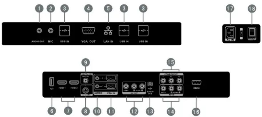
| Item Description | |
| 1 AUDIO OUT | Connects the device to headphones or speakers |
| 2 MIC | Connects to a microphone |
| 3 USB IN | Connects USB peripherals such as HDDs USB keyboards, mice and more |
| 4 VGA OUT | Connects the display with the VGA-IN connector |
| 5 LAN IN | Standard RJ45 (10M/100M/1G) Internet connection interface |
| 6 USB IN | Display Motherboard Upgrade Interface |
| 7 HDMI | High Definition Multimedia Interface |
| 8 S-VIDEO | S-VIDEO input |
| 9 COAXIAL | Coaxial output |
| 10 AUDIO IN | Connects the device to external audio sources |
| 11 VGA IN | Connects the device to external video sources |
| 12 AV OUT | Audio-Video output port |
| 13 TOUCH OUT | External PC touch-signal input |
| 14 AV IN | Audio-Video combined input port |
| 15 COMPONENT | YPbPr signal input, connect DVD, set -top -box with YPbPr |
| 16 RS232 | Serial port interface |
| 17 AC IN | AC power input |
| 18 POWER | Power On / Off switch |
Note: Model nos. CDE5501 do not have interface features #1 – 5 if the optional slot-in PC module is not installed.
SWB6552/SWB7051/SWB8451/CDE6552/CDE7051/CDE8451 Interface:
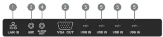

| Item Description | |
| 1 LAN IN | Standard RJ45 (10M/100M/1G) Internet connection interface |
| 2 VGA OUT | Connects the display to a VGA-IN connector |
| 3 MIC | Connects to a microphone |
| 4 AUDIO OUT | Connects the device to headphones or speakers |
| 5 USB IN | Connects USB peripherals such as HDDs USB keyboards and mice |
| 6 📋 | Display Motherboard Upgrade Interface |
| 7 TOUCH | Touch signal input, controls an external PC once the driver has been installed (available through PC, VGA and HDMI sources). |
| 8 HDMI IN | High Definition Multimedia Interface |
| 9 COAXIAL | Coaxial output |
| 10 VGA IN | Connects the device to external video sources |
| 11 AUDIO IN | Connects the device to external audio sources |
| 12 YPbPr IN | YPbPr signal input, connects to DVD players and set-top boxes |
| 13 AV IN | Audio-Video combined input port |
| 14 AV OUT | Audio-Video output port |
| 15 MIC IN | Connects to a microphone |
| 16 RS232 | Serial port interface |
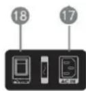
| 17 AC IN | AC power input |
| 18 POWER | Power On / Off switch |
Note: Model no. CDE6552/CDE7051/CDE8451 does not have interface features #1 – 5 if the optional slot-in PC module is not installed.
2.3 Remote Control Overview
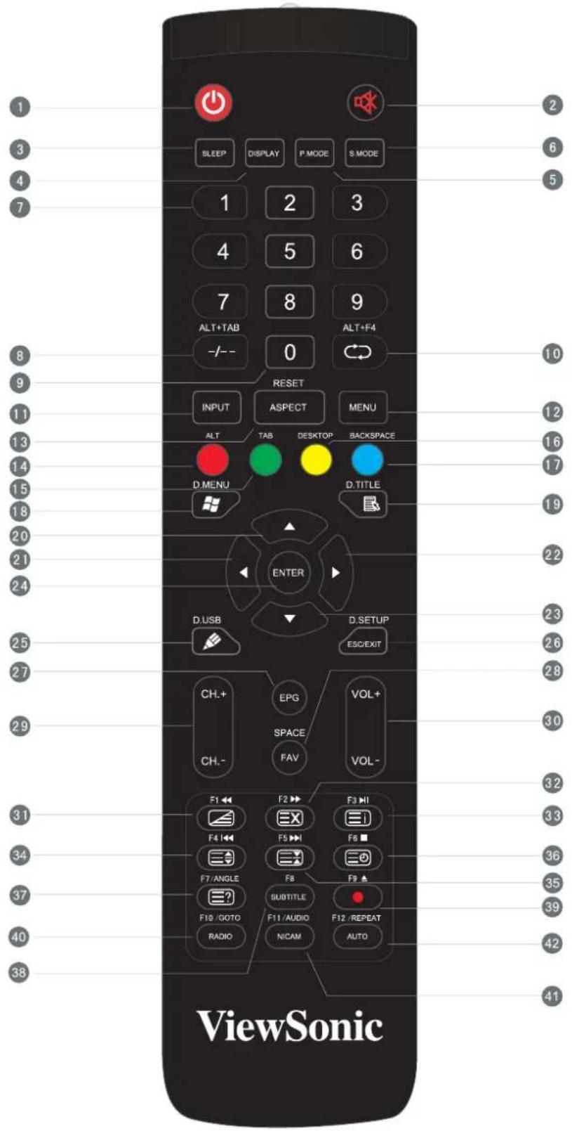

( ) :
Press to turn the display ON/OFF (Standby), or press and hold for 5 seconds to shut down

:
Mute / Unmute

SLEEP :
Set the sleep time function

DISPLAY :
Display information of the current input source

P.MODE :
Picture mode selection

S.MODE :
Sound mode selection

Numeric button:
Numeric input button

-/-、ALT+TAB:
Press to switch between PC applications

0:
Numeric input button

、ALT+F4:
Return to previous channel / Close current PC window

INPUT:
Source selection button

MENU:
Press to display Menu

RESET+ASPECT:
Adjust the aspect ratio of PC, HDMI and VGA sources

RED+ALT:
PC 'Alt' button

GREEN+TAB:
PC 'Tab' button

YELLOW+DESKTOP:
Switch to Desktop

BLUE+BACKSPACE:
PC 'Backspace' button

、D. MENU:
PC 'Windows' button

、D. TITLE:
PC 'Menu' button

▲ :
Press to scroll up

◀ :
Press to scroll left

▶ :
Press to scroll right

▼ :
Press to scroll down

ENTER:
Enter button. Press it to select options.

、D. USB:
Writing software startup

ESC/EXIT、D. SETUP:
Shortcut button to exit dialog boxes

EPG:
Digital program guide (not available)

FAV、SPACE:
PC 'Space' button

CH. +、CH. -:
Channel scroll buttons (not available)

VOL+、VOL-:
Increase / Decrease volume

◀、F1、
:
F1 Function

▶、F2、
三X:
F2 Function

▶1、F3、
三i
F3 Function

◀◀、F4、
:
4 Function

▶▶ | 、F5、
:
F5 Function

■、F6、
三
F6 Function

ANGLE、
、三?
F7 Function

SUBTITLE、F8:
F8 Function

▲、F9、
:
F9 Function

GOTO、F10、RADIO :
F10 Function

AUDIO、F11、NICAM:
F11 Function

REPEAT、F12、AUTO:
F12 Function
2.4 Inserting Remote Control Batteries
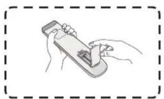
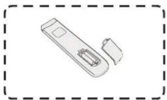
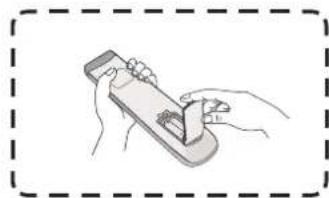
To insert the provided batteries into the remote control follow these instructions. We recommend that you don't mix battery types.
- Remove the cover on the rear of the remote control.
-
Insert two "AAA" batteries, ensuring the "+" symbol on the battery matches the "+" on the battery post.
-
Replace the cover by aligning it with the slot on the remote control and snapping the latch shut.
natural_image
Illustration of hands holding a mobile phone with a small object inside (no text or symbols visible)(1)
natural_image
Simple line drawing of a remote control device with two ports and a handle (no text or symbols)(2)
natural_image
Illustration of hands holding a handheld device with a small object inside (no text or symbols)(3)
Warning: There is a risk of explosion if batteries are replaced with the incorrect type.
Note: Always dispose of old batteries in an environmentally friendly way. Contact your local government for more information on how to dispose of batteries safely.
2.5 Remote Control Receiver Range
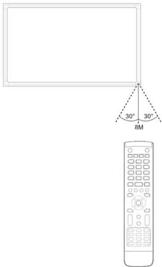
The working range of the remote control receiver is shown here. It has an effective range of 8 meters. Make sure there is nothing obstructing the remote control's signal to the receiver.
3. Setting Up Your Display
Warning: For the safety of you and your unit, please do not connect to a power supply before the external device is prepared.
3.1 Connecting an External PC
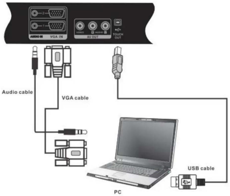
SWB5501/CDE5501 Models:
SWB6552/SWB7051/SWB8451/CDE6552/CDE7051/CDE8451 Models:
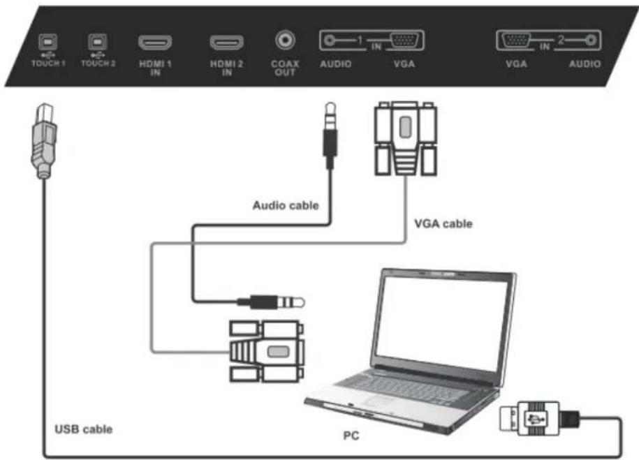
- To display video and sound from an external PC follow the instructions below.
Note: External PCs can also be connected to the display via HDMI cable.
- Connect a VGA cable (15-pin) from your external PC to the VGA IN port on the display.
-
Connect an audio cable from the AUDIO OUT port on your external PC to the AUDIO IN port on the display.
-
Connect a USB cable to the external PC from the TOUCH OUT port of the display.
-
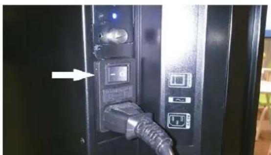
Plug the power cord into the rear panel of the display and flip the power switch (I/O) to the "I" position. The display is now in "Standby" mode.
natural_image
Close-up of a black electronic device with a metallic connector and labeled ports, showing an arrow pointing to a button (no readable text or symbols)-
Turn on your external computer and set up the touch driver.
-
Press the ⏻ button on the right-hand side of the display to turn on the screen.
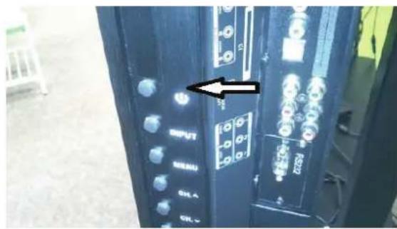
- Press the INPUT button to switch to the "PC" source.
Note: For optimal results, select 1920x1080p as the external computer's input resolution.
3.2 RS232 Connections
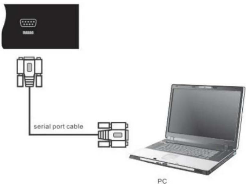
When you use a RS232 serial port cable to connect your display to an external computer, certain functions can be controlled by the PC, including power on/off, volume adjustment and more.
3.3 Connecting USB Peripherals
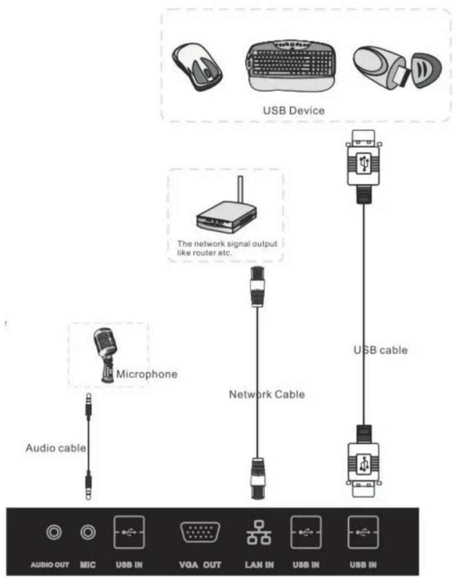
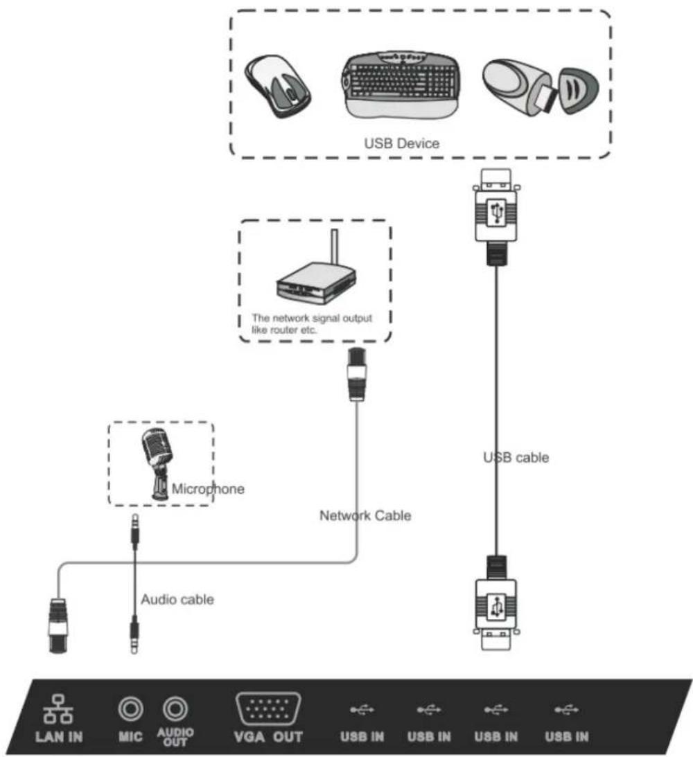
Just like a regular PC, it is easy to connect various USB devices and other peripherals with your smart whiteboard.
- USB Peripherals: Plug the USB device cable into the USB IN port.
- Networking and modem cables: Plug the router cable into the LAN IN port.
- Microphone: Plug the microphone cable into the MIC port.
SWB5501 Model:
SWB6552/SWB7051/SWB8451 Models:
flowchart
graph TD
    A["Microphone"] -->|Audio cable| B["USB Device"]
    C["USB Device"] -->|USB cable| D["USB Cable"]
    E["USB Device"] -->|The network signal output like router etc.| F["USB Device"]
    style A fill:#f9f,stroke:#333
    style B fill:#ccf,stroke:#333
    style C fill:#cfc,stroke:#333
    style D fill:#fcc,stroke:#333
    style E fill:#ffc,stroke:#333
    style F fill:#cff,stroke:#333
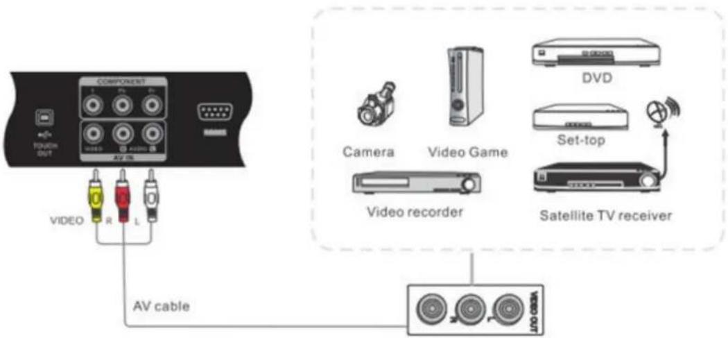
3.4 AV IN Connections
SWB5501/CDE5501 Models:
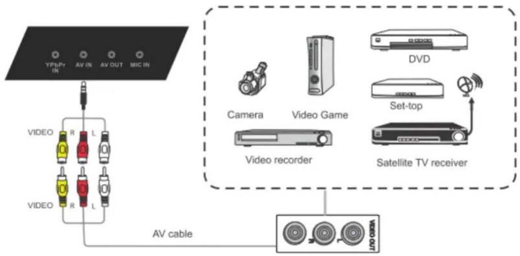
SWB6552/SWB7051/SWB8451/CDE6552/CDE7051/CDE8451 Models:
flowchart
graph TD
    A["Video"] -->|R L| B["AV cable"]
    C["Video"] -->|R L| D["AV cable"]
    E["Video recorder"] --> F["Video Game"]
    G["Set-top"] --> H["Satellite TV receiver"]
    I["DVD"] --> J["Video Game"]
    style A fill:#f9f,stroke:#333
    style C fill:#f9f,stroke:#333
    style E fill:#ccf,stroke:#333
    style G fill:#ccf,stroke:#333
    style I fill:#dfd,stroke:#333
- Connect a 3-color AV cable from the AV IN ports on your display to the AV OUT ports of a peripheral device (AV cable: Yellow is Video, Red is Audio-R, White is Audio-L).
- Plug in the power cord, and turn on the rear-panel power supply switch (see section 3.1).
- Press the button on the right-hand side of the display to turn the screen on (see section 3.1).
- Press the INPUT button to switch to the "AV" source.
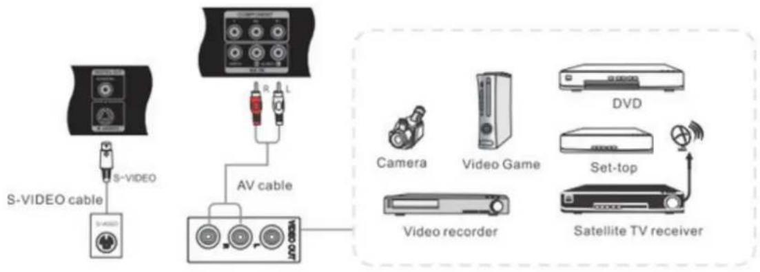
3.5 S-Video Connections
(SWB5501/CDE5501 models only)
flowchart
graph TD
    A["S-VIDEO cable"] --> B["S-VIDEO"]
    B --> C["AV cable"]
    C --> D["Video recorder"]
    D --> E["Satellite TV receiver"]
    F["Camera"] --> G["Video Game"]
    H["DVD"] --> I["Set-top"]
    J["Radio"] --> K["Radio"]
- Connect the S-VIDEO cable to the ports of the display and the peripheral device.
- Plug in the power cord, and turn on the rear-panel power supply switch (see section 3.1).
- Press the ⏻ button on the right-hand side of the display to turn the screen on (see section 3.1).
- Press the INPUT button to switch to the "S-VIDEO" source.
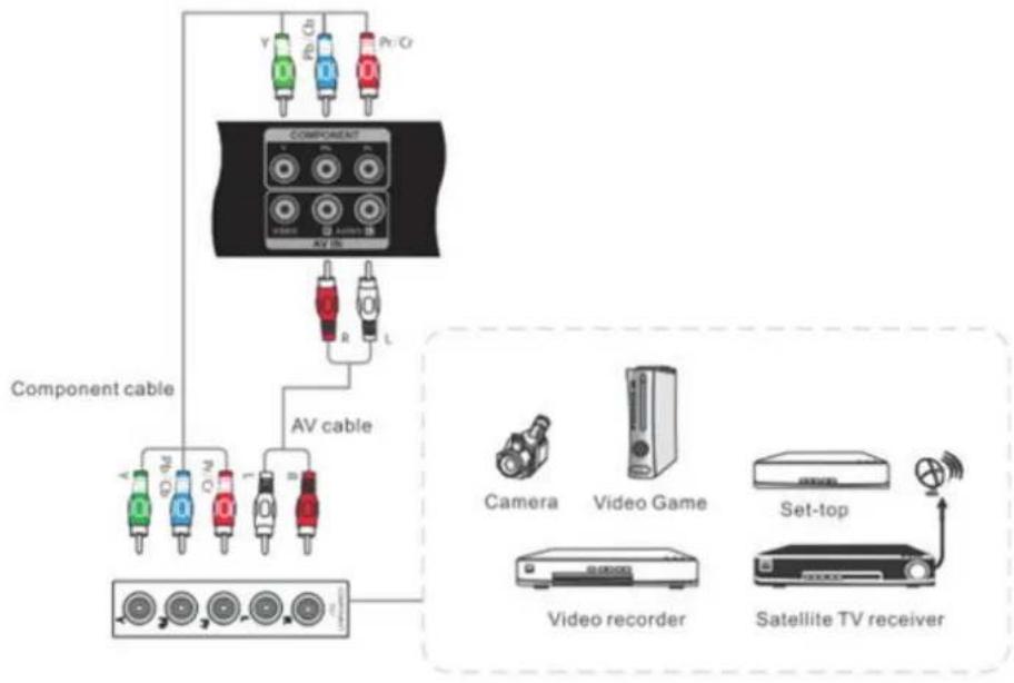
3.6 YPbPr Connections
SWB5501/CDE5501 Models:
flowchart
graph TD
    A["Component cable"] --> B["AV cable"]
    B --> C["Camera"]
    B --> D["Video Game"]
    B --> E["Set-top"]
    B --> F["Video recorder"]
    B --> G["Satellite TV receiver"]
    H["COMPONENT"] --> I["Color-coded connectors: V, E, Pr/Cr"]
    style A fill:#f9f,stroke:#333
    style B fill:#ccf,stroke:#333
    style C fill:#cfc,stroke:#333
    style D fill:#fcc,stroke:#333
    style E fill:#cff,stroke:#333
    style F fill:#ffc,stroke:#333
    style G fill:#fcc,stroke:#333
SWB6552/SWB7051/SWB8451/CDE6552/CDE7051/CDE8451 Models:
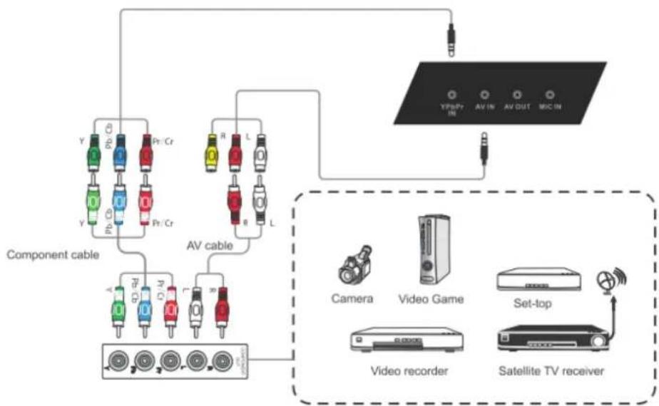
flowchart
graph TD
    A["Component cable"] --> B["AV cable"]
    B --> C["Video recorder"]
    B --> D["Set-top"]
    B --> E["Satellite TV receiver"]
    F["Camera"] --> G["Video Game"]
    G --> H["Set-top"]
    I["TV/Pr/IN"] --> J["AV OUT"]
    K["AV IN"] --> L["AV OUT"]
    M["AV IN"] --> N["AV OUT"]
- Connect the 3-color YPbPr cable from the COMPONENT ports on your display to the ports on the peripheral device.
- Plug in the power cord, and turn on the rear-panel power supply switch (see section 3.1).
- Press the ⏻ button on the right-hand side of the display to turn the screen on (see section 3.1).
- Press the INPUT button to switch to the "YPbPr" source.
3.7 HDMI Connections
SWB5501/CDE5501 Models:
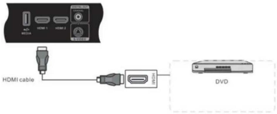
SWB6552/SWB7051/SWB8451/CDE6552/CDE7051/CDE8451 Models:
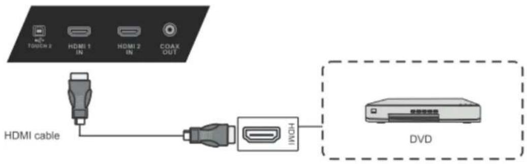
- Connect the HDMI cable to the HDMI ports on your display and peripheral device.
- Plug in the power cord, and turn on the rear-panel power supply switch (see section 3.1).
- Press the button on the right-hand side of the display to turn the screen on (see section 3.1).
- Press the INPUT button to switch to the "HDMI 1" or "HDMI 2" source.
3.8 Microphone Connections
(SWB6552/SWB7051/SWB8451/CDE6552/CDE7051/CDE8451 models only)

- Connect the microphone cable to the MIC IN jack.
- Plug in the power cord, and turn on the rear-panel power supply switch (see section 3.1).
- Press the button on the right-hand side of the display to turn the screen on (see section 3.1).
- The microphone/speakerphone can be used with all channels.
3.9 Coaxial Connections
SWB5501/CDE5501 Models:
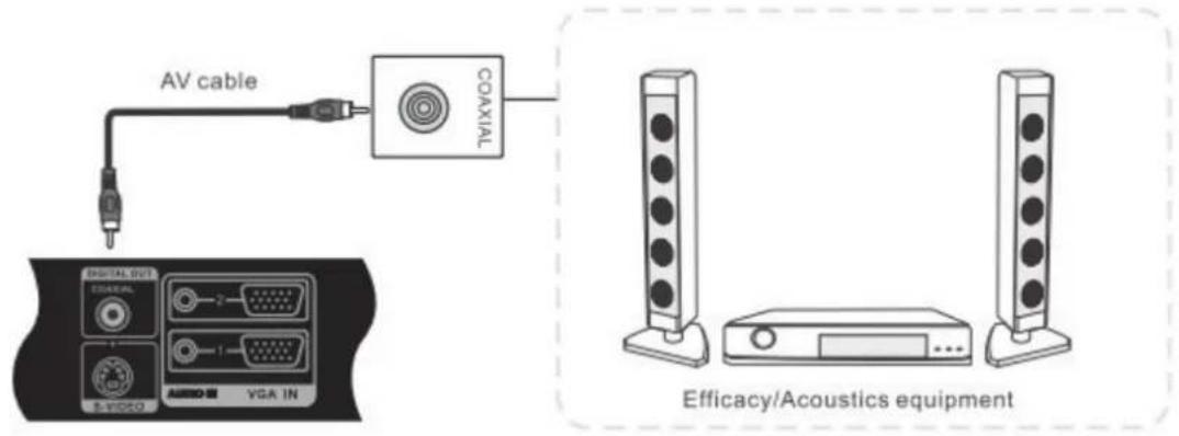
SWB6552/SWB7051/SWB8451/CDE6552/CDE7051/CDE8451 Models:
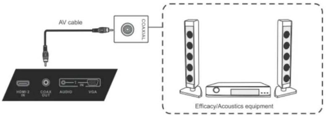
- Connect a coaxial cable from DIGITAL OUT to your sound system's coaxial connector.
- Plug in the power cord, and turn on the rear-panel power supply switch (see section 3.1).
- Press the button on the right-hand side of the display to turn the screen on (see section 3.1).
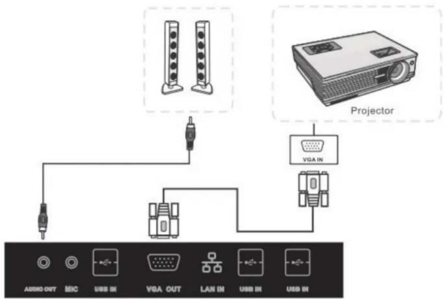
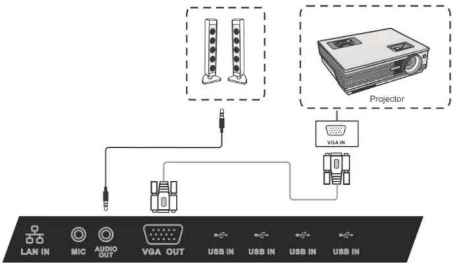
3.10 VGA Connections
SWB5501 Model:
flowchart
graph TD
    A["Audio OUT"] --> B["Microcontroller"]
    C["Microcontroller"] --> D["VGA OUT"]
    D --> E["LAN IN"]
    E --> F["Projector"]
    G["Projector"] --> H["VGA IN"]
SWB6552/SWB7051/SWB8451 Models:
flowchart
graph TD
    A["LAN IN"] --> B["LED"]
    C["MIC"] --> B
    D["AUDIO OUT"] --> B
    E["VGA OUT"] --> B
    F["USB IN"] --> G["Projector"]
    H["USB IN"] --> G
    I["USB IN"] --> G
    J["USB IN"] --> G
-
To output video and sound to an external device via VGA connection:
-
Connect a VGA cable (15-pin) from your display's VGA OUT port to the input port of a projector or other device.
-
Connect an audio cable from the AUDIO OUT port on your display to the input port of your speaker system.
-
Plug in the power cord, and turn on the rear-panel power supply switch (see section 3.1).
- Press the ⏻ button on the right-hand side of the display to turn the screen on (see section 3.1).
- Press the INPUT button to switch to the "PC" source.
- Setup the VGA OUT or Multiscreen settings on your smart display.
Note: The VGA OUT function can output images from the smart display only.
3.11 AV OUT Connections
Connecting a display:
To output video from you smart whiteboard to a second display, connect a 3-color AV cable from the AV OUT ports on your display to the AV IN ports of the secondary display (AV cable: Yellow is Video, Red is Audio-R, White is Audio-L).
SWB5501/CDE5501 Models:
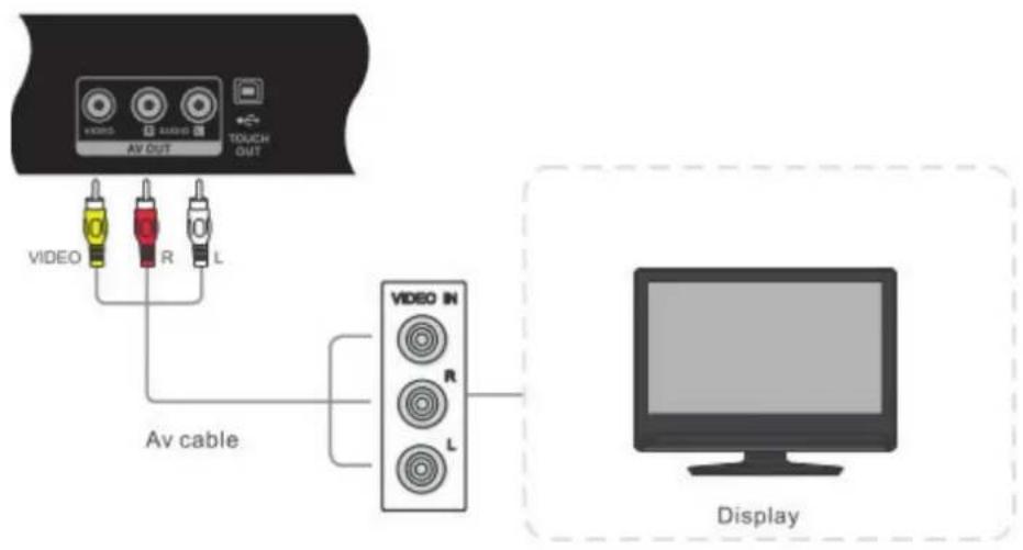
SWB6552/SWB7051/SWB8451/CDE6552/CDE7051/CDE8451 Models:
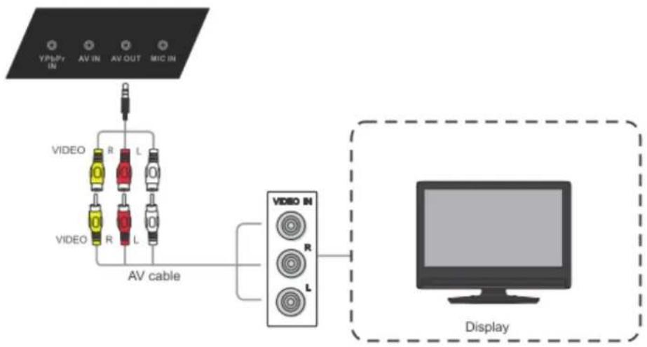
flowchart
graph TD
    A["TV Panel"] --> B["AV Cable"]
    B --> C["Video Device 1"]
    B --> D["Video Device 2"]
    B --> E["Video Device 3"]
    B --> F["Video Device 4"]
    B --> G["Video Device 5"]
    C --> H["Display"]
    D --> H
    E --> H
    F --> H
    G --> H
4. Basic Display Operations
Here are several basic display operations you should become familiar with when using your display:
Turning on the display:
Plug the display's power cord into a power source, and wait 30 seconds before pressing the ⬤ button to turn on the display and PC together.
Turning off the display:
From the Windows 8 START menu, press the POWER button on the remote control to see the message in the image below. Press the power button again to turn off both the display and PC.
![Please close PC first Press POWER key again, will close PC then standby. exit [EXIT]](/content/2026/05/1063839/images/7ac2901a71d853a22afadc2ffd1a2dab0524e197fd8b18584f306858771d8a84.jpg)
Using the Windows button:
With the display on, you can press the WINDOWS button on the remote control to jump back and forth between the desktop screen and the Windows 8 Start menu, or back and forth between the current and previous screens.
Entering Standby mode:
To enter standby mode, touch the WINDOWS button on the lower left-hand corner of the desktop screen or press the WINDOWS button on the remote control. Select OFF. This will turn off the PC, but the display will still be on.
Exiting Standby mode:
From Standby mode you can turn on the PC by pressing the INPUT button to switch back to the PC source. Both the display and the PC will now be on.
5. OSD Menu Operation
5.1 Input Source
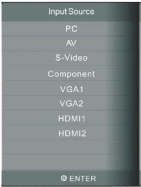
To select an input source:
- Press INPUT to display the input source list.
- Press DOWN / UP or INPUT to highlight the input source you want.
- Press ENTER to select the input source.
- Press EXIT to quit the on-screen menu.
5.2 Screen Menu
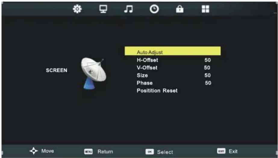
The Screen menu is available only in VGA or DVI modes. When using DVI signal input mode, only the Horizontal Position and Vertical Position can be adjusted. Press the buttons to highlight one of the following options then press ENTER to select it.

Auto Adjust: Automatically adjust H-Offset, V-Offset, Size and Phase settings. For best results, open a "full-screen" picture before executing Auto Adjust.
H-Offset: Shift the screen slightly to the left or right.
V-Offset: Shift the screen slightly up or down.
Size: Adjust the picture size.
Phase: Adjust the VGA picture signal sampling phase. This may affect image definition. A wrong value may be the fault of the interference.
Position Reset: Reset the Screen menu to default settings.
5.3 Picture Menu
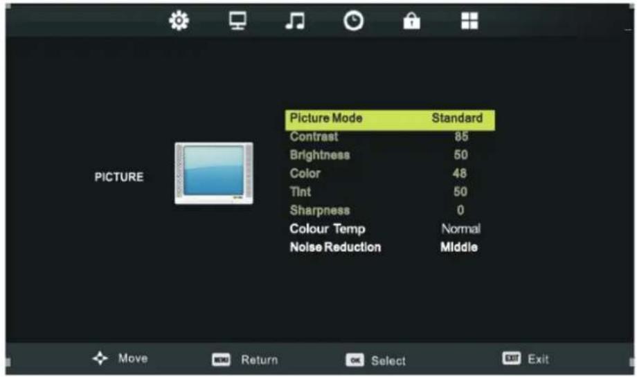
Inside the Picture menu, press the ▼ buttons to highlight one of the following options then press ENTER or ▶ to enter the sub-menu. Press EXIT to leave the on-screen menu, or press MENU to go back to the previous menu.
Picture Mode: When Picture Mode is set to personal, the following settings can be manually adjusted. You can press the P.MODE shortcut button on the remote control to select Picture Mode directly.
Contrast/Brightness/Color/Tint/Sharpness: Highlight a menu item and press ▶Press ◀/▶ to adjust the value up or down along the scale bar that appears (see below image). Tint adjustment is available for NTSC-system AV or S-video sources.

Color Temp: Press the <buttons to adjust the color temperature to one of the following:
Normal: General setting.
Cold: High color temperature.
Warm: Low color temperature.
Noise Reduction: Off/Low/Middle/High/Default.
5.4 Sound Menu
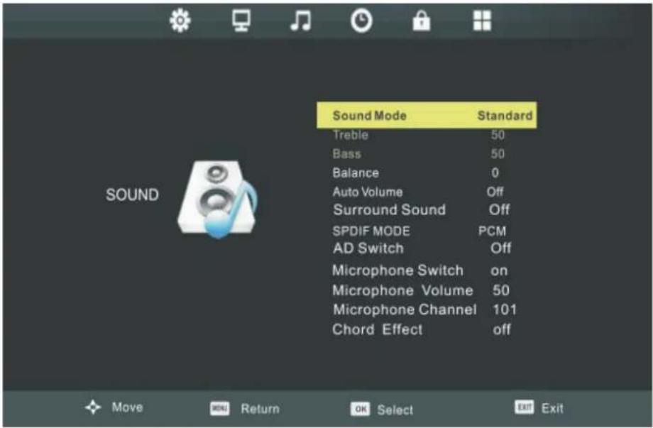
Inside the Sound menu, press the buttons to highlight one of the following options then press ENTER or ▶ to enter the sub-menu. Press EXIT to leave the on-screen menu, or press MENU to go back to the previous menu.
Sound Mode: Standard/Music/Movie/Sports/Personal. The following items can only be adjusted in "Personal" mode:
Bass: Adjust the low frequency band response.
Treble: Adjust the low frequency band response.
Balance: Adjust the level of sound coming from the left or right speakers.
Auto Volume: Reduces the sound fluctuation between channels and programs automatically.
Surround Sound: Turns Surround Sound on or off.
SPDIF MODE: Select from Off/Auto/PCM SPDIF modes.
AD Switch: Turn AD switch on or off (Not available).
Microphone Switch: Turns the microphone on or off. (SWB6552/SWB7051/SWB8451/CDE6552/CDE7051/CDE8451 models only)
Microphone Volume: Adjusts the microphone volume. (SWB6552/SWB7051/SWB8451/CDE6552/CDE7051/CDE8451 models)
Microphone Channel: Different mic settings for different channels prevent interference. (SWB6552/SWB7051/SWB8451/CDE6552/CDE7051/CDE8451 models only)
Chord Effect: Adjusts touch sounds. (SWB6552/SWB7051/SWB8451/CDE6552/CDE7051/CDE8451 models only)
5.5 Time Menu
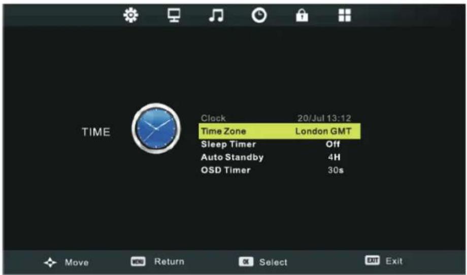
Press MENU to display the Main Menu then press the <buttons to highlight the Time Menu. Press ENTER or ▶to enter the sub-menu. In the Time Menu you can adjust the following items:
Clock: Sets the time using the digital input signal.
Time Zone: Select the time zone for your region (Note: Clock and Time Zone functions are not available).
Sleep Time: Select the time (in minutes) that you want the display to shut off automatically. You can turn off this setting at any time.
Auto Sleep: Select the amount of time (in hours) that you want the display to remain on, after the last operation, before shutting off automatically. You can turn off this setting at any time.
OSD Timer: Select the amount of time (in seconds) that you want the on-screen display to remain on after the last operation.
5.6 Lock Menu
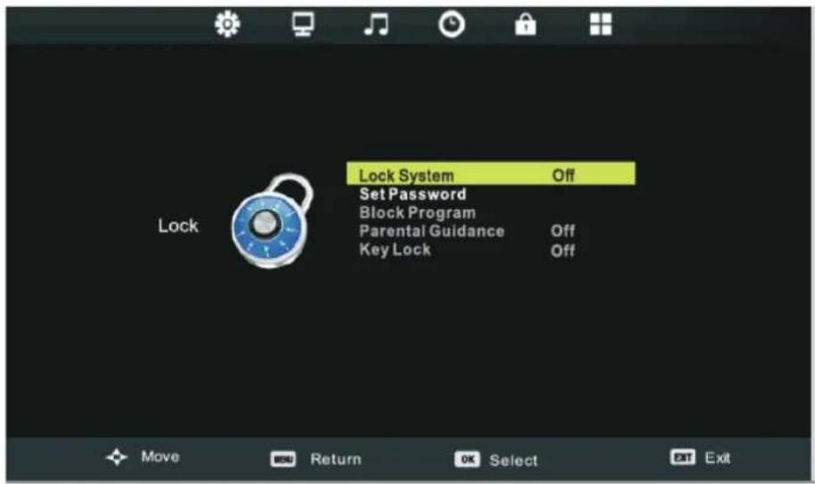
You can change the display's lock settings in the Lock Menu. To access the Lock Menu, first press MENU to display the main menu then press the buttons to select Lock Menu. Press ENTER or to enter the Lock menu.
The default password for the Lock System is "0000". The default master password is "4711". Enable the lock system by selecting "ON". To create a new password select "Set Password".
5.7 Setup Menu
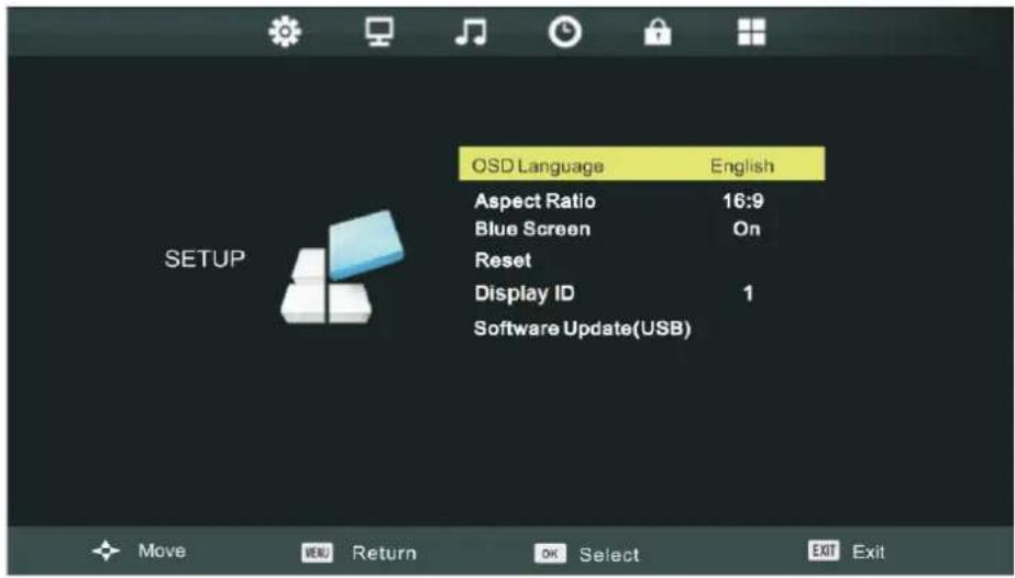
To access the Setup Menu, first press MENU to display the main menu then press the buttons to select Setup Menu. Press ENTER or to enter the Setup menu.
OSD language: Set the OSD menu language.
Aspect Ratio: Set the display image aspect ratio according to the input source.
Blue Screen: Set the screen background color for when there is no signal input.
Reset: Revert back to the default factory settings.
Display ID: To set ID number to LCD display for RS232 function.
Software Update (USB): Update your display's OS software.
6. Trouble Shooting
| Remote control is out of order | 1. Check whether something is obstructing the display's remote control receiver.2. Check whether the batteries in the remote control are installed correctly.3. Check whether the batteries need to be replaced. |
| The unit turns of unexpectedly | 1. Check whether Sleep mode is enabled.2. Check if there is a power outage in your area.3. Turn on the display and see if the problem is with the signal and control system. |
PC mode
| No PC signal 1. Check the display settings.2. Check the display resolution.3. Adjust the Hs & Vs (synchronization) settings using the OSD menu. |
| Background streaking 1. Choose auto adjust.2. Adjust clock and phase. |
| False color 1. Check the VGA connection.2. Adjust chroma, brightness and contrast settings. |
| Unsupported format 1. Choose auto adjust.2. Adjust clock and phase settings. |
Touch Function
| Touch function does not work | 1. Check that drivers are installed correctly.2. Reinstall driver.3. Check setup and align it.4. Check whether the touch pen is working properly. |
Video not working properly
| No picture / No sound 1. Check POWER status.2. Check the signal cable.3. Check that the internal PC is installed correctly. |
| Picture trembling 1. Check the signal cable.2. Check if other electronics are interrupting the signal. |
| Poor picture 1. Adjust chroma, brightness and contrast settings in the menu.2. Check the signal cable. |
Audio not working properly
| No sound 1. Press the Mute/ Unmute button. | |
| 2. Adjust the volume.3. Check the audio cable. | |
| One speaker only 1. Adjust the sound balance in the menu. | |
| 2. Check the sound control panel settings of the computer.3. Check the audio cable. | |
| No sound from VGA-OUT 1. Check that the audio cable is properly connected. | |
7. Care and Maintenance
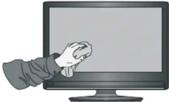
Please follow these cleaning guidelines to make sure your smart whiteboard display looks like new for years to come:
- Don't clean the machine if it has been turned on for a long period of time.
- Unplug the unit from the wall outlet before cleaning or polishing it.
natural_image
Illustration of a hand pressing down on a computer monitor (no text or symbols visible)- Don't use liquid cleaners or aerosol cleaners on the screen.
- Only use a slightly dampened cloth when cleaning the exterior of the unit.
- Don't use system continuously for long periods of time.
- Remember to unplug the display when it is not in use.
- Use a power surge protector to prevent system failures and power supply surges.
- Make sure the display remains dry at all times. Be careful when handling liquids near or on the unit.
Note: If condensation appears between the glass and the panel, keep the display turned on until the moisture disappears.
8. Display Modes
8.1 YPbPr Mode
| 480i @60Hz | |
| 480p @60Hz | |
| 576i @50Hz | |
| 576p @50Hz | |
| 720p @50Hz/60Hz | |
| 1080i @50Hz/60Hz | |
| 1080p @50Hz/60Hz |
8.2 VGA Mode
| 640x480 @60Hz/72Hz/75Hz | |
| 720x400 @70Hz | |
| 800x600 @56Hz/60Hz/72Hz/75Hz | |
| 832x624 @75Hz | |
| 1024x768 @60Hz/70Hz/75Hz | |
| 1152x870 @75Hz | |
| 1280x768 @60Hz/75Hz | |
| 1280x960 @60Hz | |
| 1280x1024 @60Hz/75Hz | |
| 1360x768 @60Hz | |
| 1440x900 @60Hz/75Hz | |
| 1920x1080 @60Hz | |
8.3 HDMI Mode
| 640x480 @60Hz/70Hz | |
| 720x400 @70Hz | |
| 800x600 @60Hz/70Hz | |
| 1024x768 @60Hz/70Hz/75Hz | |
| 1280x800 @60Hz | |
| 1280x1024 @60Hz | |
| 1360x768 @60Hz | |
| 1440x900 @60Hz | |
| 1680x1050 @60Hz | |
| 1920x1080 @60Hz | |
| 480i @60Hz | |
| 480p @59Hz/60Hz | |
| 576i @50Hz | |
| 720p @50Hz/60Hz | |
| 576p @50Hz | |
| 1080i @50Hz/60Hz | |
| 1080p @50Hz/60Hz |
9. Specifications
| Model SWB5501 | CDE5501 | SWB6552CDE6552 | SWB7051CDE7051 | SWB8451CDE8451 | |
| LCD Screen Size | 54.6" 65.5" 69.5" | 84" | |||
| Input Signal 2 x H | HDMI | 2 x VGA2 x PC audio1 x S-video1 x YPbPr1x CVBS | 2 x HDMI2 x VGA2 x PC audio1 x Mic in1 x YPbPr1x CVBS | ||
| Speaker Output | 5W x 2 | ||||
| RS232 Output RS | 232 communication | ||||
| Power Voltage | 100V-240V AC 50/60HZ | ||||
| Operation Conditions | TemperatureHumidityAltitude | 32°F to 104°F (0°C to 40°C)20% ~ 80% non-condensing≤2000M | |||
| Storage Conditions | TemperatureHumidityAltitude | -4°F to 140°F (-20°C to 60°C)10% ~ 90% non-condensing≤2000M | |||
| Dimensions Physical | ( mm) 1369 | x 828x 104 | 1544 x 937x 95 | 1649 x 999x 97 | 1979 x 1186x 86 |
| Weight Physical | (kg) 47 66 75 | 116 | |||
| Power Consumption | OnOff | 158W<0.5W | 245W<0.5W | 242W<0.5W | 560W<0.5W |
Note: Product Specifications are subject to change without notice.
10. RS-232 Protocol
10.1 Introduction
This document describes the hardware interface spec and software protocols of RS232 interface communication between ViewSonic Commercial TV / Digital Signage and PC or other control unit with RS232 protocol.
The protocol contains three sections command:
- Set-Function
- Get-Function
- Remote control pass-through mode
※ In the document below, "PC" represents all the control units that can send or receive the RS232 protocol command.
10.2 Description
10.2.1 Hardware specification
Viewsonic TV communication port on the rear side:
(1) Connector type: DSUB 9-Pin Male
(2) Pin Assignment
Male DSUB 9-Pin (outside view)
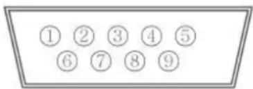
| Pin # Signal Remark | ||
| 1 NC | ||
| 2 RXD Input to Commercial TV or DS | ||
| 3 TXD Output from Commercial TV or DS | ||
| 4 NC | ||
| 5 GND | ||
| 6 NC | ||
| 7 NC | ||
| 8 NC | ||
| 9 NC | ||
| frame GND | ||
* Use of crossover (null modem) cable required for use with PC
[Special case]
3.5mm barrel connector
| Pin # Signal Remark | ||
| Tip TXD | Output from | Commercial TV or DS |
| Ring RXD | Input to | Commercial TV or DS |
| Sleeve GND | ||
10.2.2 Communication Setting
- Baud Rate Select: 9600bps (fixed)
- Data bits: 8 bits (fixed)
- Parity: None (fixed)
- Stop Bits: 1 (fixed)
10.2.3 Command Message Reference
PC sends to Monitor command packet followed by "CR". Every time PC sends control command to the Monitor, the Monitor shall respond as follows:
- If the message is received correctly it will send “+” (02Bh) followed by “CR” (00Dh)
- If the message is received incorrectly it will send “-” (02Dh) followed by “CR” (00Dh)
10.3 Protocol
10.3.1 Set-Function Listing
The PC can control the TV/DS for specific actions. The Set-Function command allows you to control the TV/DS behavior in a remote site through the RS232 port. The Set-Function packet format consists of 9 bytes.
Set-Function description:
Length: Total Byte of Message excluding "CR".
TV/DS ID Identification for each of TV/DS (01\~98; default is 01) If we want to set all TV/DS settings, use the TV/DS ID "99", and it will not have Reply command on this function. The TV/DS ID can be set via the OSD menu for each TV/DS set.
Command Type Identify command type, "s" (0x73h) : Set Command "+" (0x2Bh) : Valid command Reply "-" (0x2Dh) : Invalid command Reply
Command: Function command code: One byte ASCII code.
Value[1\~3]: Three bytes ASCII that defines the value.
CR 0x0D
Set-Function format
Send: (Command Type="s")
For VT2405LED-1 and VT3205LED, the set "Power on" command is the exception.
Reply: (Command Type="+" or "-" )
- The reply for "Power on" command is the exception for VT2405LED-1 and VT3205LED. It's 0x322B0D (2+
). - When PC applies command to all displays (ID=99), only the #1 set needs to reply by the name of ID=1.
Example1: Set Brightness as 76 for TV-02 and this command is valid Send (Hex Format)
| Name | Length ID | Command Type | Command | Value1 | Value2 | Value3 | CR |
| Hex | 0x38 0x30 0x32 | 0x73 | 0x24 | 0x30 | 0x37 | 0x36 | 0x0D |
Reply (Hex Format)
| Name | Length | ID | Command Type | CR |
| Hex | 0x34 | 0x300x32 | 0x2B | 0x0D |
Example2: Set Brightness as 176 for TV-02 and this command is NOT valid Send (Hex Format)
| Name | Length ID | Command Type | Command | Value1 | Value2 | Value3 | CR |
| Hex | 0x38 | 0x30 | 0x73 | 0x24 | 0x31 | 0x37 | 0x36 |
Reply (Hex Format)
| Name | Length ID | Command | Type | CR |
| Hex | 0x34 0x30_0x32 | 0x2D 0x0D | _ | |
Set-function table
| Set Function | Length | ID | Command Type(ASCII) Code (ASCII) Code (Hex) (Three ASCII bytes) | Range Comments | |||
| Power on/off(standby) | 8 s ! | 21 000 | 0: STBY | 001: ON | Exclude VT2405-1, and VT3205 | ||
| *Power on 6 n/a s ! 21 | 001: ON | For VT2405-1, and | VT3205 only | ||||
| Input Select | 8 s “ | 22 000 : TV | 001 : AV002 : S-Video003 : YPbPr004 : HDMI014: HDMI2024: HDMI3005 : DVI006 : VGA1 (PC)016: VGA2007: OPS | 1. No need for USB2. For the case of two more same sources, the 2^nd digital is used to indicate the extension.3. Exclude VT2405-1, and VT3205 | |||
| Contrast | 8 s | # 23 000 ~ 100 | |||||
| Brightness | 8 s | 24 000 ~ 100 | |||||
| Sharpness 8 s | % | 25 000 ~ 100 | |||||
| Color | 8 s | & | 26 000 ~ 100 | ||||
| Tint | 8 s | ‘ | 27 000 ~ 100 | ||||
| Color mode | 8 s ) | 29 000: Normal | 001: Warm002: Cold003: Personal | ||||
| Sound | 8 s - | 2D | 000: SRS Off | 001: SRS On | (for TV) | ||
| Bass | 8 | s | . | 2E | 000 ~ 100 | (for TV) | |
| Treble | 8 s / | 2F 000 ~ 100 | (for TV) | ||||
| Balance | 8 | s | 0 | 30 | 000 ~ 100 | (for TV)Sets Balance position | |
| Picture Size | 8 s | 1 | 31 000 : FULL | 001 : NORMAL002 : CUSTOM003 : DYNAMIC004 : REAL | (for DS) | ||
| OSD language | 8 s | 2 | 32 000: English | 001: French002: Spanish | Extend the value for more supported languages | ||
| OSD timeout | 8 | s | 3 | 33 | 005 ~120 Sec | Set OSD timeout | |
| Power lock | 8 s | 4 | 34 000 : Unlock | 001 : Lock | |||
| Volume 8 s 5 | 35 000 ~ | 100 | 900:Volume down(-1)901:Volume up(+1) | ||||
| Mute 8 s 6 36 | 000: OFF | 001: ON (mute) | |||||
| Off Timer 8 s | 7 37 000: | OFF | 001~024 (hour) | ||||
| PIP-Mode 8 s | 9 39 000 : | OFF | 001: PIP002: PBP | (for DS) | |||
| PIP-Sound select | 8 s : | 3A 000: Main | 001: PIP | (for DS) | |||
| PIP-Position 8 s ; 3B 000: Up | 001: Down002: Left003: Right | (for DS) | |||||
| PIP-Input 8 s < 3C 000 : TV | 001 : AV002 : S-Video003 : YPbPr004 : HDMI014: HDMI2024: HDMI3005 : DVI006 : PC/VGA007: OPS | (for DS)For the case of two more same sources, the2^{nd}digital is used to indicate the extension. | |||||
| Button lock 8 8 38 000: Unlock | 001: Lock | ||||||
| TV channel (DTV) | 8 s < | 3C | For -0:001~999A00~F99(1000~1599)For -k: 1^st and 2^nd char are same as -03th char is CHAR[ ASC(3th digi)+ k x 10 ] | (for TV)1. Channel OSD number but not frequency number2. For VT3255, VT4236 and CDE3201 only | |||
| TV channel (ATV) | 8 s = | 3D 001~999 (for TV) | |||||
| Menu lock 8 s | > 3E 000: | Unlock | 001: Lock | ||||
| Number | 8 s | @ | 40 000~009 (for TV) | ||||
| Key Pad | 8 s | A | 41 000: UP | 001: DOWN002: LEFT003: RIGHT004: ENTER005: INPUT006: MENU/EXIT | |||
| Remote Control | 8 s B | 42 000: Disable | 001: Enable002: Pass through | Disable: RCU has no effect on HDTV.Enabled: RCU controls the HDTV. This is the power up default on the HDTV.Pass through: RCU has no effect on HDTV and all RCU command codes are transmitted to FC via the RS232 port.See page 26 for more details | |||
| Setup wizard | 8 s C 43 | 000: Disable | 001: Enable | (for TV)Disable: to skip the initial setup wizard | |||
| Tiling-Mode 8 | s P 50 | 000: OFF | 001: ON | (for DS) | |||
| Tiling-Compensation | 8 s Q | 51 000: OFF | 001: ON | (for DS)Bezel width compensation | |||
| Tiling-H by V Monitors | 8 s R | 52 01x~09x: H | 0x1~0x9: V | (for DS)1.2nddigital for H monitors2.3rddigital for V monitors | |||
| Tiling-Position | 8 s S | 53 001~025 (for D$) | Copy the screen of Position# to identified display | ||||
| Restore default | 8 s ~ | 7E 000 Rests HDTV to factory | setting | ||||
NOTE:
1. Behavior at lock modes
| Lock Mode | Behavior |
| Button Lock | 1. Lock all buttons on the front panel and RCU, except for “Power”.2. All the SET functions should be workable via RS32, even the ones with according hot key in RCU like Mute,...etc. |
| MENU Lock | 1. Lock “MENU’ key on the front panel and RCU.2. The Factory and Hospitality modes should not be blocked for the model using MENU-combined key to enter these two modes. Alternative approach will be indicated separately if any limitation by model. |
| POWER Lock 1. | Lock the front and RCU “POWER” keys.2. The SET_POWER on/off should be workable via RS232, but does not mean the POWER lock will be released under this case.3. Can not be unlocked by resetting in OSD settings.4. Will auto AC power-on in power-lock5. Under power-lock, the set will not enter power saving when no PC signal and neither not turn off when no other video signals after 15min. |
| Remote control disable | Lock the RCU keys, but keep the front panel buttons workable. |
2. Example for value setting of SET\_TV channel DTV
012-0: 0x 30 31 32
012-1: 0x 30 31 42
1012-2: 0x 41 31 52
1512-3: 0x 46 31 62
3. Tiling definition of H Monitors/ V Monitors/ and Position
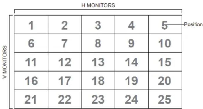
heatmap
H MONITORS | Position | 1 | 2 | 3 | 4 | 5 | | :--- | :--- | :--- | :--- | :--- | :--- | | V MONITORS | 6 | 7 | 8 | 9 | 10 | | V MONITORS | 11 | 12 | 13 | 14 | 15 | | V MONITORS | 16 | 17 | 18 | 19 | 20 | | V MONITORS | 21 | 22 | 23 | 24 | 25 |10.3.2 Get-Function Listing
The PC can interrogate the TV/DS for specific information. The Get-Function packet format consists of 9 bytes which is similar to the Set-Function packet structure. Note that the "Value" byte is always = 000
Get-Function description:
Length: Total Byte of Message excluding "CR".
TV/DS ID Identification for each of TV/DS (01\~98; default is 01).
Command Type Identify command type,
"g" (0x67h) : Get Command
“r” (0x72h) : Valid command Reply
“-” (0x2Dh) : Invalid command Reply
Command: Function command code: One byte ASCII code.
Value[1\~3]: Three bytes ASCII that defines the value.
CR 0x0D
Get-Function format
Send: (Command Type="g")
"Power STBY status" is the exception for VT2405LED-1 and VT3205LED.
Reply: (Command Type="r" or "--")
If the Command is valid, Command Type = "r"
The reply for "Power STBY status" command is the exception for VT2405LED-1 and V3205LED. It's 0x36 72 6C 30 30 30 0D (6rl000
If the Command is Not valid, Command Type="-"
Example1: Get Brightness from TV-05 and this command is valid. The Brightness value is 67.
Send (Hex Format)
| Name | Length ID | Command Type | Command | Value1 | Value2 | Value3 | CR |
| Hex | 0x38 0x300x35 | 0x67 0x6 | 2 0x30 0x30 | 0x30 0x0 | D____ | ____ | ____ |
Reply (Hex Format)
| Name | Length ID | Command Type | Command | Value1 | Value2 | Value3 | CR |
| Hex | 0x38 0x300x35 | 0x72 0x6 | 2 0x30 0x36 | 0x37 0x0 | D____ | ____ | ____ |
Example2: Get Brightness from TV-05, but the Brightness command ID is error and it is NOT in the command table.
Send (Hex Format)
| Name | Length ID | Command Type | Command | Value1 | Value2 | Value3 | CR |
| Hex | 0x38 0x30 0x35 | 0x67 | 0XD3 | 0x30 0x30 0x30 | 0x0D | _ |
Reply (Hex Format)
| Name | Length ID | Command Type | CR |
| Hex | 0x34 0x30 0x35 | 0x2D | 0x0D |
Get-Function table
| Get Function | Length | ID | Command Type(ASCII) | Command | Response Range(Three ASCII bytes) | Comments | |
| Code (ASCII) | Code (Hex) | ||||||
| Get-Contrast | 8 | g | a | 61 | 000 ~ 100 | ||
| Get-Brightness | 8 | g | b | 62 | 000 ~ 100 | ||
| Get-Sharpness | 8 g c | 63 000 ~ 100 | ||||
| Get-Color 8 g | d 64 000 | ~ 100 | ||||
| Get-Tint 8 g e | 65 000 ~ 100 | |||||
| Get-Volume 8 | g f 66 000 | 00 ~ 100 | ||||
| Get-Mute 8 g | g 67 000: | Off | 001: On (muted) | |||
| Get-Input select | 8 g j | 6A 000~ See Set-function | table | |||
| *Get-Power status: STBY | 6 n/a | g l | 6C | 000 | For VT2405-1 and | VT3205 only |
| Get-Power status: ON/ STBY | 8 g l | 6C | 001: ON | Exclude VT2405-1, and VT3205 | ||
| Get-Remote control | 8 g n | 6E | 000: Disable | Gets RCU mode status | ||
| Get-Power lock | 8 g o | 6F 000: Unlock | 001: Lock | |||
| Get-Button lock | 8 g p | 70 000: Unlock | 001: Lock | |||
| Get-Menu lock | 8 g q | 71 000: Unlock | 001: Lock | |||
| Get-Setup wizard | 8 g s | 73 000: Disable | (for TV) | |||
| Get-PIP mode | 8 g t | 74 000 : OFF | (for DS) | |||
| Get-PIP input | 8 g u | 75 000 ~ | (for DS) | See Set-function table | ||
| Get-Tiling Mode | 8 g v | 76 000: OFF | (for DS) | |||
| Get-Tiling Compensation | 8 g | w | 77 000: OFF | (for DS)Bezel width compensation | ||
| Get-Tiling H by V monitors | 8 g x | 78 01x~09x: | (for DS)1. 2^nd digital for H monitors2. 3^rd digital for V monitors | |||
| Get-Tiling position | 8 g y | 79 000: OFF | (for DS)Copy the screen of Position# to identified display | |||
| Get-ACK | 8 g z | 7A | 000 | This command is | used to test the communication link | |
10.3.3 Remote Control Pass-through mode
When the PC sets the TV/DS to Remote Control Pass through mode, the TV/DS will send a 7-byte packet (followed by "CR") in response to RCU button activation. Note, that in this mode the RCU shall have no effect on the TV/DS function. For example: "Volume+" will not change the volume in the LCD but only sends "Volume+" code to PC over the RS232 port.
IR Pass Through-Function format
Reply: (Command Type="p")
Example1: Remote Control pass-through when "VOL+" key is pressed for TV-05 Send (Hex Format)
| Name | Length ID | Command | Type | RCU Code1 (MSB) | RCU Code2 (LSB) | CR |
| Hex | 0x36 | 0x30 | 0x70 0x31 | 0x30 0x0D | — | — |
| Key Code (HEX) | |
| 1 | 01 |
| 2 | 02 |
| 3 | 03 |
| 4 | 04 |
| 5 | 05 |
| 6 | 06 |
| 7 | 07 |
| 8 | 08 |
| 9 | 09 |
| 0 | 0A |
| - | 0B |
| RECALL (LAST) | 0C |
| INFO (DISPLAY) | 0D |
| 0E | |
| ASPECT (ZOOM, SIZE) | 0F |
| VOLUME UP (+) | 10 |
| VOLUME DOWN (-) | 11 |
| MUTE | 12 |
| CHANNEL/PAGE UP (+)/ BRIGHTNESS+ | 13 |
| CHANNEL/PAGE DOWN (-)/ BRIGHTNESS-POWER 15 | 14 |
| SOURCES (INPUTS) 16 | |
| 17 | |
| 18 | |
| SLEEP 19 | |
| MENU 1A | |
| UP 1B | |
| DOWN 1C | |
| LEFT (-) 1D | |
| RIGHT (+) 1E | |
| OK (ENTER, SET) 1F | |
| EXIT 20 | |
| 21 | |
| 22 | |
| 23 | |
| 24 | |
| 25 | |
| 26 | |
| 27 | |
| 28 | |
| 29 | |
| 2A | |
| 2B | |
| RED ■ (F1) 2C | |
| GREEN ■ (F2) 2D | |
| YELLOW ■ (F3) 2E | |
| BLUE ■ (F4) 2F |
NOTE:
- This IR-pass-through code is different from the RCU key code.
- Special control sequence for POWER key under IR-pass through mode.
2-1. When TV/DS is OFF and receives the IR POWER code: TV/DS will turn itself on, then forward the POWER code to the host via RS232.
2-2. When TV/DS is ON and receives the IR POWER code: TV/DS will forward the POWER code to the host via RS232, then turn off itself.
2-3. When SET-POWER LOCK is enabled, the TV/DS will not respond to POWER key pressing. - The VOLUME UP and VOLUME DOWN code will repeatedly output when you press and hold the keys.
Other Information
Customer Support
For technical support or product service, see the table below or contact your reseller.
NOTE: You will need the product serial number.
| Country/Region Website | T = TelephoneF = FAX | ||
| AustraliaNew Zealand | www.viewsonic.com.au | AUS= 1800 880 818NZ= 0800 008 822 | service@au.viewsonic.com |
| Canada www.viewsonic.com | T (Toll-Free)= 1-866-463-4775T (Toll)= 1-424-233-2533F= 1-909-468-3757 | service.ca@viewsonic.com | |
| Europe www.viewsoniceurope.com www.viewsoniceurope.com/uk/support/call-desk/ | |||
| Hong Kong www.hk.viewsonic.com T= 852 3102 2900 service@hk.viewsonic.com | |||
| India www.in.viewsonic.com T= 1800 266 0101 service@in.viewsonic.com | |||
| Korea www.kr.viewsonic.com T= 080 333 2131 service@kr.viewsonic.com | |||
| Latin America(Argentina) | www.viewsonic.com/la/ T= 0800-4441185 soporte@viewsonic.com | ||
| Latin America(Chile) | www.viewsonic.com/la/ T= 1230-020-7975 soporte@viewsonic.com | ||
| Latin America(Columbia) | www.viewsonic.com/la/ T= 01800-9-157235 soporte@viewsonic.com | ||
| Latin America(Mexico) | www.viewsonic.com/la/ T= 001-8882328722 soporte@viewsonic.com | ||
| Renta y Datos, 29 SUR 721, COL. LA PAZ, 72160 PUEBLA, PUE. Tel: 01.222.891.55.77 CON 10 LINEASElectroser, Av Reforma No. 403Gx39 y 41, 97000 Mérida, Yucatán. Tel: 01.999.925.19.16Other places please refer to http://www.viewsonic.com/la/soporte/index.htm#Mexico | |||
| Latin America(Peru) | www.viewsonic.com/la/ T= 0800-54565 soporte@viewsonic.com | ||
| Macau | www.hk.viewsonic.com T= 853 2870 0303 service@hk.viewsonic.com | ||
| Middle East | ap.viewsonic.com/me/ | Contact your reseller | service@ap.viewsonic.com |
| Puerto Rico & Virgin Islands | www.viewsonic.com | T= 1-800-688-6688 (English)T= 1-866-379-1304 (Spanish)F= 1-909-468-3757 | service.us@viewsonic.comsoporte@viewsonic.com |
| Singapore/Malaysia/Thailand | www.ap.viewsonic.com | T= 65 6461 6044 service@sg.viewsonic.com | |
| South Africa | ap.viewsonic.com/za/ | Contact your reseller | service@ap.viewsonic.com |
| United States | www.viewsonic.com | T (Toll-Free)= 1-800-688-6688T (Toll)= 1-424-233-2530F= 1-909-468-3757 | service.us@viewsonic.com |
Limited Warranty
ViewSonic® Smart White Board
What the warranty covers:
ViewSonic warrants its products to be free from defects in material and workmanship, under normal use, during the warranty period. If a product proves to be defective in material or workmanship during the warranty period, ViewSonic will, at its sole option, repair or replace the product with a like product. Replacement product or parts may include remanufactured or refurbished parts or components.
How long the warranty is effective:
ViewSonic Smart White Board is warranted for 1 year, depending on your country of purchase, for all parts including the light source and for all labour from the date of the first consumer purchase
Who the warranty protects:
This warranty is valid only for the first consumer purchaser.
What the warranty does not cover:
- Any product on which the serial number has been defaced, modified or removed.
- Damage, deterioration or malfunction resulting from:
a. Accident, misuse, neglect, fire, water, lightning, or other acts of nature, unauthorized product modification, or failure to follow instructions supplied with the product.
b. Any damage of the product due to shipment.
c. Removal or installation of the product.
d. Causes external to the product, such as electrical power fluctuations or failure.
e. Use of supplies or parts not meeting ViewSonic's specifications.
f. Normal wear and tear.
g. Any other cause which does not relate to a product defect.
- Any product exhibiting a condition commonly known as "image burn-in" which results when a static image is displayed on the product for an extended period of time.
- Removal, installation, one way transportation, insurance, and set-up service charges.
How to get service:
- For information about receiving service under warranty, contact ViewSonic Customer Support (Please refer to Customer Support page). You will need to provide your product's serial number.
- To obtain warranty service, you will be required to provide (a) the original dated sales slip, (b) your name, (c) your address, (d) a description of the problem, and (e) the serial number of the product.
- Take or ship the product freight prepaid in the original container to an authorized ViewSonic service center or ViewSonic.
- For additional information or the name of the nearest ViewSonic service center, contact ViewSonic.
Limitation of implied warranties:
There are no warranties, express or implied, which extend beyond the description contained herein including the implied warranty of merchantability and fitness for a particular purpose.
Exclusion of damages:
ViewSonic's liability is limited to the cost of repair or replacement of the product. ViewSonic shall not be liable for:
- Damage to other property caused by any defects in the product, damages based upon inconvenience, loss of use of the product, loss of time, loss of profits, loss of business opportunity, loss of goodwill, interference with business relationships, or other commercial loss, even if advised of the possibility of such damages.
- Any other damages, whether incidental, consequential or otherwise.
- Any claim against the customer by any other party.
- Repair or attempted repair by anyone not authorized by ViewSonic.
Effect of state law:
This warranty gives you specific legal rights, and you may also have other rights which vary from state to state. Some states do not allow limitations on implied warranties and/or do not allow the exclusion of incidental or consequential damages, so the above limitations and exclusions may not apply to you.
Sales outside the U.S.A. and Canada:
For warranty information and service on ViewSonic products sold outside of the U.S.A. and Canada, contact ViewSonic or your local ViewSonic dealer.
The warranty period for this product in mainland China (Hong Kong, Macao and Taiwan Excluded) is subject to the terms and conditions of the Maintenance Guarantee Card.
For users in Europe and Russia, full details of warranty provided can be found in www.viewsoniceurope.com under Support/Warranty Information.
Smart White Board Warranty Term Template In UG
VSC_TEMP_2013

natural_image
Three colorful bird illustrations perched on a branch against a red background (no text or symbols)ViewSonic®
- Compliance Information
- FCC Compliance Statement
- Industry Canada Statement
- CE Conformity for European Countries
- Following information is only for EU-member states:
- Declaration of RoHS2 Compliance
- Cautions and Warnings
- Contents
- Copyright Information
- Getting Started
- Smart Whiteboard/LCD Display Features
- Setting Up Your Display
- Basic Display Operations
- OSD Menu Operation
- Trouble Shooting
- Care and Maintenance
- Display Modes
- Specifications
- RS-232 Protocol
- Other Information
- Product Registration
- Product disposal at end of product life
- Package Contents
- Wall Mount Kit Specifications (VESA)
- Control Panel Overview
- Terminal Interface Overview
- ( ) :
- :
- ▲ :
- ▼ :
- Inserting Remote Control Batteries
- Remote Control Receiver Range
- Connecting an External PC
- SWB6552/SWB7051/SWB8451/CDE6552/CDE7051/CDE8451 Models:
- RS232 Connections
- Connecting USB Peripherals
- AV IN Connections
- S-Video Connections
- YPbPr Connections
- HDMI Connections
- Microphone Connections
- Coaxial Connections
- VGA Connections
- AV OUT Connections
- Connecting a display:
- Turning on the display:
- Turning off the display:
- Using the Windows button:
- Entering Standby mode:
- Exiting Standby mode:
- Input Source
- To select an input source:
- Screen Menu
- Picture Menu
- Sound Menu
- Time Menu
- Lock Menu
- Setup Menu
- Introduction
- Description
- Hardware specification
- Communication Setting
- Command Message Reference
- Protocol
- Set-Function Listing
- Set-Function description:
- Set-Function format
- NOTE:
- Behavior at lock modes
- Example for value setting of SET\_TV channel DTV
- Tiling definition of H Monitors/ V Monitors/ and Position
- Get-Function Listing
- Get-Function description:
- Remote Control Pass-through mode
- IR Pass Through-Function format
- Customer Support
- Limited Warranty
- ViewSonic® Smart White Board
- What the warranty covers:
- How long the warranty is effective:
- Who the warranty protects:
- What the warranty does not cover:
- How to get service:
- Limitation of implied warranties:
- Exclusion of damages:
- Effect of state law:
- Sales outside the U.S.A. and Canada:
Brand : VIEWSONIC
Model : SWB6552
Category : Screen