
PD HVcompact - Electric meter Megger - Free user manual and instructions
Find the device manual for free PD HVcompact Megger in PDF.

| Product Type | Digital high voltage meter |
| Brand | Megger (manufactured by Power Diagnostix) |
| Model | PD HVcompact |
| Dimensions (W x H x D) | 236 x 133 x 300 mm |
| Weight | Approx. 3.5 kg |
| Power Supply | 100-240 V AC, 50/60 Hz automatic |
| Power Consumption | Approx. 20 VA |
| Display | Backlit LCD, 128 x 240 pixels B/W |
| Input Voltage | 100 V RMS or ±200 V peak |
| Input Impedance | 5 MΩ // 200 pF |
| Frequency Range | 20-510 Hz (firmware dependent) |
| Measurement Precision | < 0.5% + 0.5 V |
| A/D Converter | ±11 bit |
| Samples per Cycle | 197 |
| Operating Temperature | 10-40 °C (non-condensing) |
| Recorder Output | 0-10 V DC, 100 Ω |
| Relay Contacts | 250 V, 5 A (voltage limit and breakdown) |
| Main Functions | Auto-ranging oscilloscope and meter display, U DC, U RMS, û, û/√2, crest factor, adjustable voltage limit, divider ratio, breakdown detection (dU/dt), measurement history, up to 7 saveable parameter setups |
| Safety Features | Protective grounding required, voltage limit relay, breakdown relay, keyboard lock, low voltage discriminator |
| Maintenance | Annual calibration recommended; no regular maintenance required |
| Optional Interfaces | RS-232 (57.6 kB) and LAN (RJ-45) |
| Housing Options | 19-inch rack or half 19-inch desktop |
| Repairability | Contact manufacturer for service; careful packing required for shipment |
Frequently Asked Questions - PD HVcompact Megger
User questions about PD HVcompact Megger
0 question about this device. Answer the ones you know or ask your own.
Ask a new question about this device
Download the instructions for your Electric meter in PDF format for free! Find your manual PD HVcompact - Megger and take your electronic device back in hand. On this page are published all the documents necessary for the use of your device. PD HVcompact by Megger.
USER MANUAL PD HVcompact Megger
© Copyright 2024 by Power Diagnostix Instruments GmbH. All rights reserved.
The contents of this manual are the property of Power Diagnostix Instruments GmbH. No part of this work may be reproduced or transmitted in any form or by any means without the written permission of the publisher. Product and company names herein may be the trademarks of their respective owners.
Power Diagnostix reserves the right to alter the specification of its products from time to time without notice. Although every effort is made to ensure the completeness and accuracy of the information contained within this document, it is not warranted or represented by Power Diagnostix to be a complete and up-to-date description.
This manual supersedes all previous issues of this manual. Please ensure that you are using the most recent issue of this document.
HVcompact
Digital high voltage meter
LANGUAGE | EN
USER GUIDE
Contents
1 General 5
1.1 About this manual....5
1.2 Instrument safety 5
2 Introduction 6
3 Installation 7
4 Menus....9
4.1 Main menu 9
4.1.1 Scope display ("MAIN S" menu) 9
4.1.2 Meter display ("MAIN M" menu)....9
4.2 Scale menu = Scaling of the meter.... 10
4.3 Result menu = Measurement history.... 10
4.4 Setup menu 11
4.5 Reset to default settings.... 13
5 Miscellaneous....14
5.1 Maintenance 14
5.2 Product marks 14
5.3 Shipment Instructions 14
5.4 Declaration of Conformity 15
5.5 UK Declaration of Conformity 16
6 Technical data....17
6.1 Optional features.... 17
1 General
1.1 About this manual
This manual describes the hardware and usage of the HVcompact in its current version. Revisions of this manual and current brochures are available for download (Adobe's PDF format) through Power Diagnostix's website (www.pdix.com). Access to the download area of the website is password protected and requires a valid maintenance contract.
Some of the hardware features of the most recent versions are not available with earlier versions of the instrument. It is possible to upgrade most of the previous instruments to the features of the current instruments. Please contact Power Diagnostix for details (support@pdix.com).
1.2 Instrument safety
Before using the HVcompact, read the following safety information and this manual carefully. Especially read and obey the information, which are marked with the words 'Warning' and 'Caution'. The word 'Warning' is reserved for conditions and actions that pose hazards to the user, while the word 'Caution' is reserved for conditions and actions that may damage the instrument, or its accessories, or that may lead to malfunction.
Always obey the safety rules given with the warnings and with this chapter. Especially take care of the safety issues while performing field measurements. Never disregard safety considerations even under time constraints found often with on-line and off-line test on site.

Warning
● Always ensure solid grounding of the instrument. Never operate the instrument without protective grounding.
- Use isolation techniques, such as isolation transformers or fibre optic isolation to avoid hazard and injury. With applications bearing a high risk of electrical shock or breakdown, use fibre optic isolation in general.
- Do not work alone.
- Do not allow the instrument to be used if it is damaged or its safety is impaired.
- Inspect the ground leads and signal cables for continuity.
- Select the proper coupling circuit and connection for your application.
- Do not use the instrument in an environment where there is risk of condensation or risk of explosion.
HVcompact
Digital high voltage meter
2 Introduction
The HVcompact is a high voltage (HV) meter with an auto-ranging oscilloscope and meter display of the voltage. The unit further displays U DC, U RMS, , /2 , the measurement frequency, and the crest factor. To improve the readability, one of four measurement values is displayed using large characters. For the protection of test specimens, the unit offers a adjustable voltage limit, which trips a relay output if the limit is exceeded. The divider ratio is freely adjustable and is kept in a non-volatile memory.
The HVcompact comes either in a 19-inch housing, which can be placed in a 19-inch rack, or in a half 19-inch desktop housing that allows tabletop operation. In case of a 19-inch desktop housing, the integrated feet of the instrument must be folded out to provide proper ventilation of the HVcompact. Five buttons are arranged to the right-hand side of the backlit liquid crystal display (LCD) for the control of the instrument. The brightness control of the LCD is located beneath these buttons. A small screwdriver is needed to access the brightness control. The instrument automatically compensates for changes of the brightness due to changing of the ambient temperature.
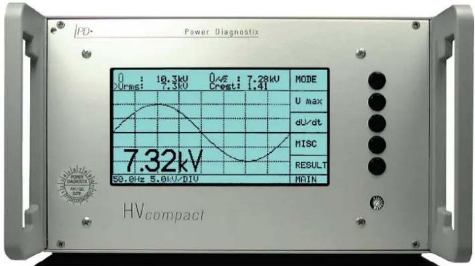
Figure 1: HVcompact in a half 19-inch desktop housing
3 Installation
Before using the HVcompact, the following wiring must be done:
- Mains power supply (adjusts automatically between 100 V and 240 V AC)
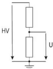
- Voltage signal of an HV divider connected via coaxial cable (RG58) to the "U in" BNC jack (max. 200 V _peak )
- If required, interconnection of the relay output with the test set control (see Figure 4)
- If required, connection of a paper recorder to the "REC" output
Solid system grounding using the wing nut terminal
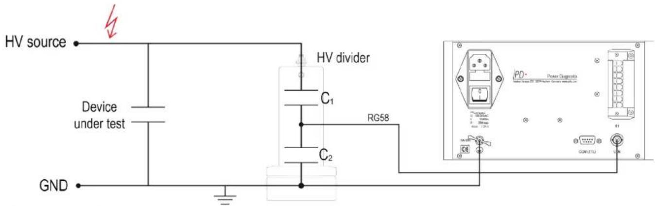
Figure 2: Connection principle
HVcompact
Digital high voltage meter
The rear panel of the HVcompact carries the power supply socket including the mains switch, the connector for the relay output and the recorder output (REC), the wing nut terminal for ground connection, the serial connector "COM TTL" and the BNC connector for the voltage signal input ("V in").
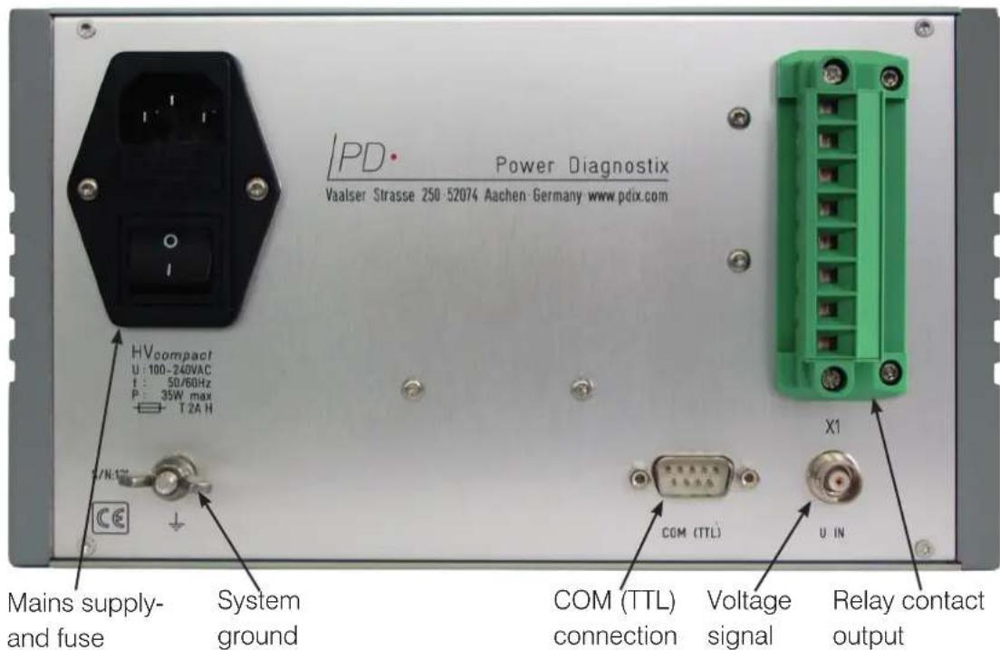
Figure 3: Rear panel of the HVcompact
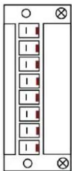
The relay contact output is connected via an 8-pin plug component (PC4/8ST-7,62). The pin connection for this plug is shown in Figure 4.
natural_image
Pure electrical circuit lines without any symbolsX1:1
X1:2
X1:3
X1:4
X1:5
X1:6
X1:7
X1:8
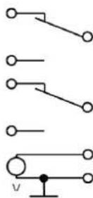
Figure 4: Connections of the 8-pin connector
4 Menus
4.1 Main menu
Directly after powering up, the unit displays the HVcompact logo. Subsequently, the instrument selects the display of the last selected MAIN menu. The display mode can be changed by METER and SCOPE.
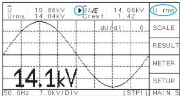
4.1.1 Scope display ("MAIN S" menu)
Provided, the input voltage signal is big enough (> \~0.5 V) and the frequency is found between 20 Hz and 510 Hz (20 Hz and 300 Hz with older versions), the voltage waveform is displayed in a way that one cycle can be seen. The voltage curve is scaled automatically, if the signal reaches 10 % of its nominal value (\~10 V). The scaling factor of the graticule can be found in the lower line next to the synchronisation frequency.
line
| Parameter | Value | | --------- | --------- | | U | 19.88kV | | Urms | 14.04kV | | U/Rms | 14.06kV | | dU/dt | 0 | | SCALE | - | | RESULT | - | | METER | - | | SETUP | - | | 50.0Hz | 14.1kV | | 7.0kV/DIV | (STP1) |Figure 5: Main menu in SCOPE mode
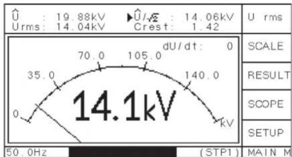
4.1.2 Meter display ("MAIN M" menu)
By default, the scaling of the METER display is done automatically according to the input voltage and the set divider factor. In the menu SCALE, the scaling of the METER display can be changed manually. This setting will be stored until the automatic mode is selected ('>AUTO').
other
| Measurement | Value | | :--- | :--- | | Voltage (kV) | 19.88 | | Voltage (kV) | 14.06 | | Voltage (kV) | 14.04 | | Voltage (kV) | 1.42 | | Scale | | | RESULT | | | SCOPE | | | SETUP | | | 50.0Hz | (STP1) MAIN MFigure 6: Main menu in METER mode
From the acquired waveform, the instrument calculates the peak voltage ( ), the effective voltage (U RMS), the peak voltage divided by the square root of two ( /2 ), the crest factor ( /U RMS) and, if "U DC" is selected, the mean voltage. The period to calculate the mean value of "U DC" is taken from the synchronisation frequency, which is shown in the lower left corner of the display (usually 50 or 60 Hz).
The top button will select, which of the four values is shown using largems \\
characters. This setting additionally selects, which of the voltage values is recorded in the menu "RESULT" and which value is used for the low voltage discriminator (either /2 or U RMS). The symbol in the upper two display lines indicates, which of the values is selected (see Figure 5). If the DC voltage is selected, the display of the waveform will change accordingly.
HVcompact
Digital high voltage meter
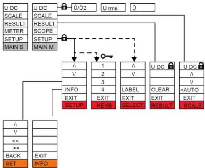
The main menus ("MAIN S" and "MAIN M") have several submenus. From these submenus, "EXIT" will always return to the main menu. Figure 7 gives an overview of the menu structure. If the system is locked (see also "SETUP" menu, "KEYB"), each menu marked with the symbol will lead to the KEYB menu ( ), where the code 2321 can be entered to unlock the system.
flowchart
graph TD
    A["U DC"] --> B["SCALE"]
    B --> C["RESULT"]
    C --> D["METER"]
    D --> E["SETUP"]
    E --> F["MAIN S"]
    G["U DC"] --> H["SCALE"]
    H --> I["RESULT"]
    I --> J["SCOPE"]
    J --> K["SETUP"]
    K --> L["MAIN M"]
    M["✓/Ö2"] --> N["↓"]
    O["U rms"] --> P["↓"]
    Q["✓"] --> R["↓"]
    S["✓"] --> T["↓"]
    U["✓"] --> V["↓"]
    W["✓"] --> X["↓"]
    Y["✓"] --> Z["↓"]
    AA["✓"] --> AB["↓"]
    AC["✓"] --> AD["↓"]
    AE["✓"] --> AF["↓"]
    AG["✓"] --> AH["↓"]
    AI["✓"] --> AJ["↓"]
    AK["✓"] --> AL["↓"]
    AM["✓"] --> AN["↓"]
    AO["✓"] --> AP["↓"]
    AQ["✓"] --> AR["↓"]
    AS["✓"] --> AT["↓"]
    AU["✓"] --> AV["↓"]
    AW["✓"] --> AX["↓"]
    AY["✓"] --> AZ["SET"]
    BA["✓"] --> BB["EXIT"]
    BC["<<"] --> BD["INFO"]
Figure 7: Menu overview
4.2 Scale menu = Scaling of the meter
"UP" and "DOWN" will manually adjust and fix the scaling. The automatic scaling function is active when the label ">AUTO" is marked.
4.3 Result menu = Measurement history
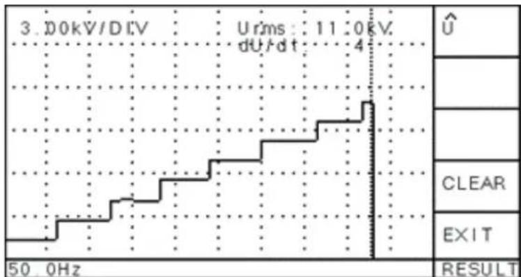
The menu "RESULT" permanently records the selected voltage, i. e., the value, which is displayed in large characters. The most recent 197 values are shown, and a cursor line indicates the current time position. The scaling factor is displayed in the upper left-hand corner. The button "CLEAR" will remove all values and re-start the recording. It will also set the counter for the dU/dt values to zero. Figure 8 shows an example record display, where the measured voltage was increased stepwise.
line
| Time (Hz) | Voltage (kV) | |---|---| | 3.0 | Urms: 11:0kV, dU/dt: 4 | | 50.0 | U |Figure 8: Exemplary display of the result menu
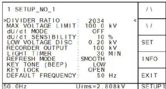
4.4 Setup menu
In the "SETUP" menu, parameter can be set to adapt the instrument to a specific test configuration. If the HVcompact is used at different locations or with different voltage dividers, up to seven different parameter setups can be saved. The whole setup can be changed and labelled in the menu "SELECT", which is accessible by selecting the top line of the "SETUP" menu.
← Moves one up, to enter the "SELECT" menu
← Moves one down, for changing the max. voltage limit
← Opens the "SET" menu for changing the divider ratio
← Opens the menu "INFO"
⇐ Moves back to the main menu
Figure 12: Setup menu
Within the menu "SELECT", the button "LOAD" activates the selected setup. The name of the activated setup is shown in the bottom line.
The button "LABEL" will switch to the menu EDIT, where the setup name (label) can be changed. Valid characters for the label are the ten digits, the underscore, and all capital letters. The changed value/character is saved immediately without confirmation.
Within the menu "SETUP", single parameters of the active setup can be changed. The button "SET" leads to a submenu, where the single digits of the value can be modified. The menu "INFO" shows details about the hard- and software version of the instrument, as well as contact details of Power Diagnostix.
DIVIDER RATIO
The divider ratio of the HV voltage divider has to be inserted as a factor of 1:x. E.g., with a divider factor of 1000, a maximum measuring range of 140 kV is possible when the maximum voltage input is: V_in max. = 140 V _eff
The calculated voltage is shown in the bottom line on the right-hand side. After pressing the "SET" button, the value can be increased (' ') or decreased (' ') digit by digit until the voltage equals a known voltage value, given by, e.g., sphere gap calibration or a temporarily installed meter.
MAX VOLTAGE LIMIT 🔒
A maximum voltage level for / 2 or U DC can be set to trigger the relay switch _max on the rear panel. If the voltage / 2 or U DC exceeds the set limit, the contact between X1:5 and X1:6 is closed (see Figure 4).
dU/dt MODE (only firmware versions > 1.20)
The dU/dt mode defines the action taken after a breakdown has occurred. With "OFF" selected, nothing will be done. With "COUNTER" selected, the number of breakdowns is displayed. This number can be set to zero by "RESULT" and "CLEAR". With "RELAY" selected, a breakdown will switch the dU/dt relay (see Figure 4).
dU/dt SENSITIVITY (only firmware versions > 2.0)
The different settings are "VERY LOW", "LOW", "MEDUIM", "HIGH" and "VERY HIGH". The voltage values of two successive cycles are compared. The maximum deviation in percent of the maximum voltage is compared with a predefined value, depending on this setting. The setting "VERY LOW" allows a higher deviation than
HVcompact
Digital high voltage meter
"VERY HIGH". If this deviation exceeds the limit and the "RELAY" mode is selected, the relay contact X1:1 - X1:2 is opened (see Figure 4).
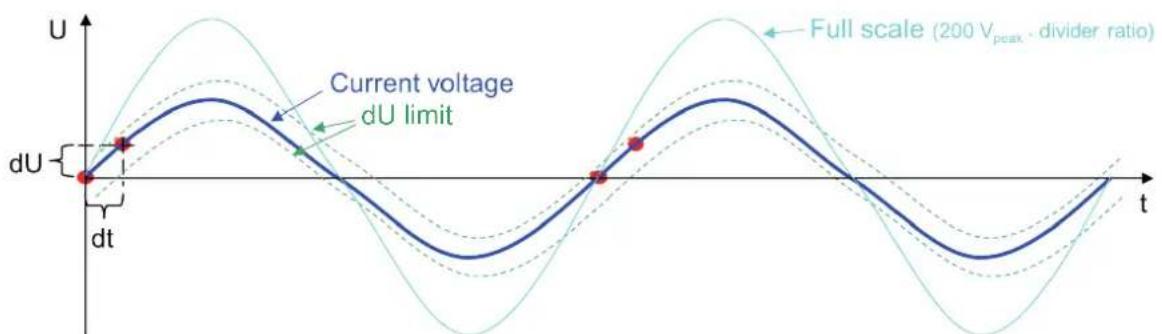
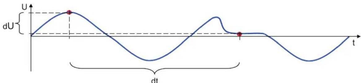
dU/dt LIMIT (firmware versions > 1.19)
In this setting, a maximum voltage change per time [kV/ms] can be set to detect single voltage dips. In case a single breakdown or flashover occurs and the dU/dt value is exceeded, the relay contact X1:1 – X1:2 is opened (see Figure 4).
The minimum dU/dt value must be larger than the maximum rise time of the waveform. With sine waves this is at 0°. Since one whole cycle is sampled with 100 values, the dwell time will be 1/(f·100). With the firmware version 1.20 and greater, the voltage values of two following samples are compared. With dU being calculated by ·(3.6^) the minimum setting can be calculated by: min= 8.881000· f·2
As rough approximation, the set value can be calculated by: min = ·150
= current peak voltage => peak of the operating voltage (with firmware version 1.20)
= full scale voltage = >200V peak* divider ratio (with firmware version 1.21)
With firmware version 1.21, the dU/dt value is automatically adjusted to the current voltage value.
line
| t | U (dU limit) | |-------|--------------| | 0 | 0 | | 1 | ~0.5 | | 2 | ~0.8 | | 3 | ~0.6 | | 4 | ~0.9 | | 5 | ~0.7 | | 6 | ~0.8 | | 7 | ~0.6 | | 8 | ~0.9 | | 9 | ~0.7 | | 10 | ~0.8 | | 11 | ~0.6 | | 12 | ~0.9 | | 13 | ~0.7 | | 14 | ~0.8 | | 15 | ~0.6 | | 16 | ~0.9 | | 17 | ~0.7 | | 18 | ~0.8 | | 19 | ~0.6 | | 20 | ~0.9 | | 21 | ~0.7 | | 22 | ~0.8 | | 23 | ~0.6 | | 24 | ~0.9 | | 25 | ~0.7 | | 26 | ~0.8 | | 27 | ~0.6 | | 28 | ~0.9 | | 29 | ~0.7 | | 30 | ~0.8 | | 31 | ~0.6 | | 32 | ~0.9 | | 33 | ~0.7 | | 34 | ~0.8 | | 35 | ~0.6 | | 36 | ~0.9 | | 37 | ~0.7 | | 38 | ~0.8 | | 39 | ~0.6 | | 40 | ~0.9 | | 41 | ~0.7 | | 42 | ~0.8 | | 43 | ~0.6 | | 44 | ~0.9 | | 45 | ~0.7 | | 46 | ~0.8 | | 47 | ~0.6 | | 48 | ~0.9 | | 49 | ~0.7 | | 50 | ~0.8 | | 51 | ~0.6 | | 52 | ~0.9 | | 53 | ~0.7 | | 54 | ~0.8 | | 55 | ~0.6 | | 56 | ~0.9 | | 57 | ~0.7 | | 58 | ~0.8 | | 59 | ~0.6 | | 60 | ~0.9 | | 61 | ~0.7 | | 62 | ~0.8 | | 63 | ~0.6 | | 64 | ~0.9 | | 65 | ~0.7 | | 66 | ~0.8 | | 67 | ~0.6 | | 68 | ~0.9 | | 69 | ~0.7 | | 70 | ~0.8 | | 71 | ~0.6 | | 72 | ~0.9 | | 73 | ~0.7 | | 74 | ~0.8 | | 75 | ~0.6 | | 76 | ~0.9 | | 77 | ~0.7 | | 78 | ~0.8 | | 79 | ~0.6 | | 80 | ~0.9 | | 81 | ~0.7 | | 82 | ~0.8 | | 83 | ~0.6 | | 84 | ~0.9 | | 85 | ~0.7 | | 86 | ~0.8 | | 87 | ~0.6 | | 88 | ~0.9 | | 89 | ~0.7 | | 90 | ~0.8 | | 91 | ~0.6 | | 92 | ~0.9 | | 93 | ~0.7 | | 94 | ~0.8 | | 95 | ~0.6 | | 96 | ~0.9 | | 97 | ~0.7 | | 98 | ~0.8 | | 99 | ~0.6 | | 100 | ~0.9 |Figure 9: dU/dt value with firmware version 1.21 and higher
You should add 10 % to this value, depending on the input level and the overall noise to avoid an unwanted tripping. Strong harmonics will influence the natural waveform, and therefore the dU/dt value has to be adapted.
dU/dt LIMIT (only firmware versions < 1.19)
With firmware versions < 1.19, the peak voltage of two successive cycles is compared. Therefore, the theoretical minimum dU/dt value is zero. However, instabilities and manual voltage changes require a minimum dU/dt value.
line
| t | dU | | ---- | ------ | | 0.0 | 0.0 | | 0.5 | 1.0 | | 1.0 | 0.0 | | 1.5 | -1.0 |Figure 10: dU/dt value with firmware version up to 1.19
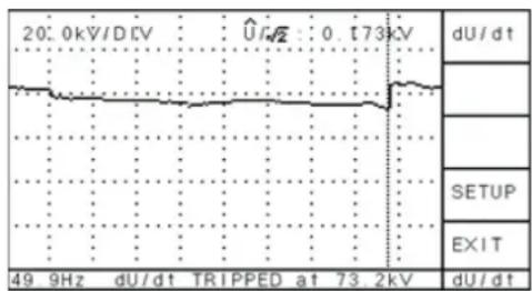
RESULT
If the dU/dt mode is "RELAY" and a voltage dip is recognised, the instrument changes to the "RESULT" menu. Within this menu, the cursor indicates the occurrence of the breakdown. The voltage level just before the breakdown is indicated in the bottom line, whereas the actual voltage is shown in the top line. Pressing any active button exits this display and resumes the recording of voltage values in the "RESULT" menu.
line
| Time (kHz) | Voltage (kV) | |------------|--------------| | 49 | ~0.0 | | 9 | ~0.0 | | dU/dt | ~0.0 | | dU/dt | 0.0 | | dU/dt | 173.2 | | dU/dt | 2 |Figure 11: Setup menu
LOW VOLTAGE DISC
If the calculated voltage (either U RMS, /2 , or U DC, depending on the selection) is below this level, all voltage values are set to 0 V.
RECORDER OUTPUT
The recorder output terminal (x1:7 and x1:8, see Figure 4) may optionally be connected to a paper recorder or other device to provide a graph of the voltage magnitude. The voltage output gives 0 to 10 V DC and corresponds linearly to the displayed (selected) voltage. If, e.g., the "REC" level is set to 100 kV and the display shows 65 kV, the voltage output equals 6.5 V. The REC output value is altered together with the selection of the displayed voltage.
LIGHT TIMER for the LCD
The back light of the LC display is turned off automatically when no button is pressed. The time delay can be set to a value from 1 to 60 minutes. A shorter time helps saving lifetime of the LCD.
REFRESH MODE
The shown peak values are calculated by up to ten measurements if the voltage level is stable. This smoothing of the values increases the accuracy and should be turned on if possible. However, if a fast display of the values is required, this mode can be turned off.
KEY TONE (BEEP)
In this menu the sound when pushing a button can be changed or turned off.
KEY LOCK
The menu "KEYB" allows locking the keyboard ("LOCK"), leaving only functions available that will not affect the integrity of the measurement. Selecting one of the locked menus:
"U max", "DIV", "LVD", "dU/dt", "RECOUT", "SCALE"
will lead to the "KEYB" menu. To unlock the keyboard, the digit sequence 2321 must be entered.
DEFAULT FREQUENCY (only firmware versions > 2.0)
If there is no voltage at the input of the HVcompact, the default frequency is displayed with an asterisk in front. 50 Hz and 60 Hz are selectable.
4.5 Reset to default settings
To restore the factory default settings of an HVcompact, press the top and bottom buttons of the button line at the right-hand side simultaneously when switching on the device.
HVcompact
Digital high voltage meter
5 Miscellaneous
5.1 Maintenance
The HVcompact should be calibrated on an annual basis to ensure that its output signal remains within the recommended boundaries. Besides that, the HVcompact does not require any maintenance on a regular basis.
5.2 Product marks
This symbol indicates that the product should not be disposed of as normal household waste. As it is a B2B product, it may also not be disposed of at civic disposal centres. If you wish to dispose of this product, please do so properly by taking it to an organisation specialising in the disposal of old electrical equipment near you.

natural_image
Simple line drawing of a trash bin with crossed lines indicating no waste or discharge (no text or symbols)Any batteries installed must be disposed of separately from the unit.
As a responsible manufacturer, who is certified according to ISO 14001, Power Diagnostix offers customers to take back old instruments. Please contact Power Diagnostix at support@pdix.com to discuss the procedure for this.
5.3 Shipment Instructions
In case a unit needs to be returned to the factory, make sure the acquisition unit is packed safely. As the units are relatively small, shipment by couriers, such as DHL, FedEx, or equivalent is the recommended mode of transportation. If possible, declare the instrument as 'used instruments for evaluation' at a relative low value. Consult Power Diagnostix for further details. Additionally, Power Diagnostix may provide you with a temporary replacement unit in case of urgent needs.
5.4 Declaration of Conformity
The manufacturer
Power Diagnostix Instruments GmbH
Vaalser Strasse 250
52074 Aachen
Germany

declares that the product
HVcompact
Digital high voltage meter
provided it is installed, maintained, and used for which it was made, in accordance with relevant installation standards and manufacturer's instruction, meets the requirements of the following directive(s):
Low Voltage Directive 2014/35/EU
EMC Directive 2004/108/EG
RoHS Directive 2011/65/EU
It complies with the following standards and/or normative documents:
EN 61010-1:2020
EN 61326-1:2013
EN IEC 63000:2018
Aachen, 29/02/2024
Dr. Mihai Huzmezan
(CEO, Power Diagnostix Instruments GmbH)
Remark: Since the measurement of partial discharge pulses is done in frequency bands partly occupied by radio transmission, and since further test leads may act as antennas, disturbance free measurements may require well-shielded environments and/or additional filter techniques.
HVcompact
Digital high voltage meter
5.5 UK Declaration of Conformity
The manufacturer
Power Diagnostix Instruments GmbH
Vaalser Strasse 250
52074 Aachen
Germany

declares that the product
HVcompact
Digital high voltage meter
provided it is installed, maintained, and used for which it was made, in accordance with relevant installation standards and manufacturer's instruction, meets the requirements of the following Statutory Instruments:
SI 2016 no. 1101 The Electrical Equipment (Safety) Regulations 2016
SI 2016 no. 1091 The Electromagnetic Compatibility Regulations 2016
SI 2012 no. 3032 The Restriction of the Use of Certain Hazardous Substances in Electrical and Electronic Equipment Regulations 2012
It complies with the following standards and/or normative documents:
EN 61010-1:2020
EN 61326-1:2013
EN IEC 63000:2018
Aachen, 29/02/2024
Dr. Mihai Huzmezan
(CEO, Power Diagnostix Instruments GmbH)
Remark: Since the measurement of partial discharge pulses is done in frequency bands partly occupied by radio transmission, and since further test leads may act as antennas, disturbance free measurements may require well-shielded environments and/or additional filter techniques.
6 Technical data
Mains supply: 100–240 V AC, 50/60 Hz (automatic)
Line fuse — 1.6 A (time-lag)
Power requirements: Approx. 20 VA
Display: Backlit LCD
Display resolution: 128 x 240 pixels B/W
Operation: 5 menu supported buttons
Input: 100 V RMS or ±200 Vpeak
Input impedance: 5 MΩ // 200 pF
Frequency range: 20–300 Hz (> firmware version 1.03)
20–510 Hz (> ver. 1.14)
Precision: <0.5% +0.5 V
A/D converter: ±11 bit
Samples: 197 samples per cycle,
e.g., 20 ms @ 50 Hz ->100 μs per sample
Operation temperature: 10–40 °C (non-condensing)
Overall size: 236 x 133 x 300 mm ^4 (W x H x D, exclusive connectors)
Weight: Approx. 3.5 kg
Recorder output: 0–10 V with RO = 100 Ω (BNC connector)
Voltage limit (Umax): One single-pole, double-throw contact max. \~250 V, 5 A
Break-down limit (dU/dt): One single-pole, double-throw contact max. \~250 V, 5 A
6.1 Optional features
Serial interface: RS-232, 57.6 kB
LAN interface: RJ-45
HVcompact
Digital high voltage meter
LANGUAGE | EN
USER GUIDE
Power Diagnostix Systems GmbH · Vaalser Strasse 250 · 52074 Aachen Germany · Telephone +49 241 74927 · Fax +49 241 79521 · www.pdix.com
HVcompact_UG_e1.00 February 2024
© Power Diagnostix Systems GmbH 2024
- HVcompact
- Contents
- General
- About this manual
- Instrument safety
- Warning
- Digital high voltage meter
- Introduction
- Installation
- Menus
- Main menu
- Scope display ("MAIN S" menu)
- Meter display ("MAIN M" menu)
- Scale menu = Scaling of the meter
- Result menu = Measurement history
- Setup menu
- DIVIDER RATIO
- MAX VOLTAGE LIMIT 🔒
- RESULT
- LOW VOLTAGE DISC
- RECORDER OUTPUT
- LIGHT TIMER for the LCD
- REFRESH MODE
- KEY TONE (BEEP)
- KEY LOCK
- Reset to default settings
- Miscellaneous
- Maintenance
- Product marks
- Shipment Instructions
- Declaration of Conformity
- UK Declaration of Conformity
- Technical data
- Optional features
Brand : Megger
Model : PD HVcompact
Category : Electric meter