FM-K574 - Car accessory American International - Free user manual and instructions
Find the device manual for free FM-K574 American International in PDF.


| Product Type | Kitchen Food Scale |
| Model Number | FM-K574 |
| Brand | American International |
| Maximum Weight Capacity | 5 kg (11 lbs) |
| Graduation | 1 g (0.1 oz) |
| Power Source | 2 x AAA batteries (not included) |
| Display | LCD screen |
| Platform Material | Tempered glass |
| Unit Selection | g, kg, lb, oz, ml, fl.oz |
| Auto-off | After 2 minutes of inactivity |
| Tare Function | Yes |
| Dimensions (L x W x H) | 20 x 15 x 2 cm |
| Net Weight | 350 g |
| Cleaning | Wipe with damp cloth; do not immerse in water |
| Safety Features | Overload indication, low battery indicator |
| Spare Parts Availability | Contact manufacturer for replacements |
Frequently Asked Questions - FM-K574 American International
User questions about FM-K574 American International
0 question about this device. Answer the ones you know or ask your own.
Ask a new question about this device
Download the instructions for your Car accessory in PDF format for free! Find your manual FM-K574 - American International and take your electronic device back in hand. On this page are published all the documents necessary for the use of your device. FM-K574 by American International.
USER MANUAL FM-K574 American International
VEHICLEAPPLICATIONS
Ford
1996-99TAURUS
Mercury
1996-99SABLE
FM-K574mountingKit
KITOVERVIEW
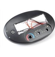
This installationkit is designed to replace the original integrated factory radio with rotary climate control assembly, while utilizing and maintaining the factory rotary climate control this kit.
TheFM-K574kitallowsforasingleDINorsingleISOmountradiotobeinstalledwhile keepingthefactorycosmeticsandclimatecontrolfunctionsintact.TheFactoryradio/climatecontrolpanelitselfisonlyaslaveunit.Theamplifier/tunermoduleislocated inthetrunkontheleftsideunderthetrunkliner,orforwagonsbehindthesparetire ontheleftside.
FACTORYRADIOREMOVAL
- Engagethecarsemergencybrake.
- With the key out of the ignition, turn all climate control knob to astraight up and down position.
- YouwillneedapairofFordRadioRemovalKeys(part#URT-460)toremovethe factoryradio/climatecontrolassembly.
- Insert the Radioremovalkeys into the holes on the face of the radio or climate control panel until they click into place. Firmly grip the keys while expressing the keys gently outward to depress them metal retaining clips attached to the sides of the radio or climate control assembly. Pull the entire radio or climate control assembly forward to access the wiring and rearmounted climate controls.
- Sub-dashmodificationmaybenecessaryonvehicleswithcenterconsoles. SeeFigureA.

FACTORYCLIMATECONTROLREMOVALINSTRUCTIONS
Readtheseinstructionsthoroughlypriortotheremovalofthefactoryclimatecontrols.
- Carefully removethethreeclimate controlknobs from the face of the radio/climate control panel by pulling outward.
- Removethesinglescrewsecuringthetemperatureswitchtotherearofthefactory radio/climatecontrolpanelthentwisttheswitchclockwisetoremove.
- Removethesinglescrewsecuringthefanswitchtotherearofthefactory radio/climatecontrolpanelthentwistthefanswitchcounter-clockwisetoremove.
- Removethe(3) Torxscrews from therearoftheclimatecontrolassembly.
- Carefully un-do thethinstripoftapeatthebottomedgeoftherearoftheclimate controlassembly(donotremoveentirely) thistapewillbere-setlater.
- Carefullyseparatethebottomofthecontrolassemblypanelaboutaquarterofaninch.
- Usingasmallflatbladescrewdriver, unfastentheflowdirectionswitch'sclipsfrom therearofthepanelandremoveflowdirectionswitch.
- RemovetheindividualT-15Torxscrewfromeachsideofthefactoryradio/climate controlsecuringthemetalmountingbracketstothefactoryassembly.SeeFigureB.
- Usingasmallflatbladescrewdriver, prythemetalclipsupwardtoreleaseandremove.
- Re-attachthefactorymountingbracketstotherearoftheFM-K574panelthesame waytheywereattachedtothefactoryassembly.SeeFigureB.
Attachfactorymountingbrackets toeachsideasshowninFig.B

DINMOUNTINSTRUCTIONS
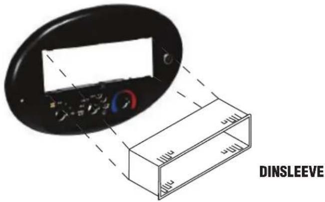
- Insert DINsleeve from your new radioint the opening of the installation kit.
- Depressthetabsfrominsidethesleevesopeningupward, outward, and downward to securesleevetotheinstallationkit.
- Installradiointosleeveandlockintoplace.
- Attacharearsupportbrackettotherearofthenewradioandadjustasnecessaryto attachtotherearsupportbarlocatedabovetheradioopeningonthebacksideofthe FM-K574panel.
ISOMOUNTINSTRUCTIONS
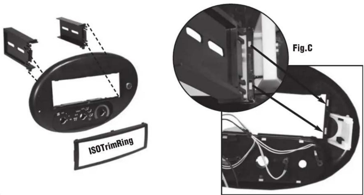
- AttachISOmountbracketstorearofkitasshowninFigureC.
- Insert ISO mountableradiobetween ISO mountbracketsandlooselyattachtosides ofradiousingscrewsprovidedwithradiowhenpossible.
- AttachISOtrimringtofaceofkit.
4.Slideradioforwardorbackwardfordesiredlookandtightenscrews. - Attacharearsupportbrackettotherearofthenewradioandadjustasnecessaryto attachtotherearsupportbarlocatedabovetheradioopeningonthebacksideofthe FM-K574panel.
POWER&SPEAKERCONNECTIONS
ThewiringharnessadaptersoftheFM-K574kitarecolorcodedandlabeledforfunction. TheGreyharnessisforpowerandground.TheBlackharnessisforspeakers.Besure tomatchthewiresfromyournewradiotoourharnessescorrectly.Yourradio'swires maydifferintheircolorsandterminology.Readyourradiowiringinstructionscarefully andmatchthecorrespondingwirestoourharnesses.Defrosterharness(white2wire connector)mustbeconnectedpriortore-installingassemblyindash.Capoffany unusedwiresindividuallywithelectricaltape,buttconnectorsorcrimpcapstoprevent accidentalshorting.
SPEAKERCONNECTIONINFORMATION
TheBlackspeakerconnectorhas8colorcodedwiresinit.4wiresarepositivespeaker leadsand4wiresarenegativespeakerleads.Ifyournewstereohasonlyasinglenegativewireforthespeakers,twistall4ofthenegativespeakerwiresontheBlack harnessoftheFM-K574togetherandconnectthenewradio'snegativespeakerwireto thethese4combinedwires.Ifthesinglenegativewireisalsotheradio'sprimaryground wire,youwillneedtoconnectthegroundwirefromtheGreyharnessoftheFM-K574 tothe4negativespeakerwiresontheBlackharnessoftheFM-K574ANDthesingle (ground/negative)speakerwirefromthenewstereo.
Ifyournewradiohasonlyasingleftandsinglerightspeakerpositivewireonit,you willneedtoconnect2ofthepositivewiresontheBlackharnessoftheFM-K574kitto onesinglepositivespeakerwirefromthenewstereo(I.E.)forfronttorearfading capability,youwillconnecttherighttandleftfrontspeakerpositivewiresfromthe BlackharnessoftheFM-K574togetherandthenconnecteitherthesingleleft,orsingle rightspeakerwirefromthenewstereotothesecombinedwires.Dothesameforthe rear.Forlefttorightbalanceonly,connecttherightfrontpositiveandrightrearpositive speakerwiresfromtheblackharnesstogetherandconnecttherightpositivespeaker wirefromthenewstereo.Connecttheleftfrontpositiveandleftrearpositivespeaker wiresfromtheblackharnesstogetherandconnecttheleftpositivespeakerwirefrom thenewstereo.
FACTORYAMPLIFIERandTUNERINFORMATION
Readtheseinstructionsthoroughlypriortowiringyouraftermarketradio.
- The factory amplifier/tunerislocated in the trunk, conserved or behind the spare tire on wagons.
- Disconnectthefactoryharnessandantennaleadfromthefactoryamplifier.
- Connectthewireharnessandtheantennaleadextension, includedintheFM-K574 kit, totheharnessandantennaleadremovedfromthefactoryamplifier/tuner.
- Routetheharnessandantennaextensionleadtotheradio/dashcavity.
- Wireyouraftermarketradioaccordingtotheinstructionsincludedwithyourradio, matchingeachwiretotheFM-K574wireharness. Eachwireislabeledforfunction.
ForinformationaboutotherAmericanInternationalautomotive accessoriesvisitourwebsiteat:
http://www.americaninternational.net

American International
AutomotiveProductsDivision
1040AvenidaAcaso•Camarillo,CA93012,U.S.A.
USASales(800)336-6500
CanadaSales(888)922-3006•USAFax(805)388-7950
CUSTOMERHELPLINE
USA800-323-4329•Canada800-245-8777


Brand : American International
Model : FM-K574
Category : Car accessory