
WiseNet SMT-2701PVM - Monitor Hanwha - Free user manual and instructions
Find the device manual for free WiseNet SMT-2701PVM Hanwha in PDF.


| Product Type | LCD Public View Monitor |
| Brand | Hanwha |
| Model | WiseNet SMT-2701PVM |
| Screen Size | 27 inches |
| Display Resolution | Supports up to 1080p (HDMI) |
| Aspect Ratio | 16:9 (4:3 selectable via OSD) |
| Power Supply | DC 12V-24V Wide Range, 3.6A max (12V) / 1.8A max (24V) |
| Power Adapter | 60W 12V DC adapter included |
| Input Connectors | VGA (D-sub 15pin), HDMI, Camera (RJ45), Audio In (stereo), USB (firmware update) |
| Net Weight | 7.7 kg (17.1 lbs) |
| Gross Weight | 10.4 kg (23 lbs) |
| Packing Dimensions (L x W x H) | 769 x 162 x 608 mm (30.2 x 6.3 x 23.9 in) |
| VESA Mount | 100x100 mm / 200x100 mm, M4 x 5mm screws |
| Cabinet Material | Metal, finish Black |
| OSD Controls | Physical buttons (Menu, Source, Up/Down, Power) and remote control |
| Remote Control | Included (requires 2xAAA batteries) |
| Audio | Stereo audio input, volume control, mute function |
| Cleaning Instructions | Use damp cloth only; do not use alcohol, spirits, or ammonia |
| Safety Features | Grounded plug, do not block ventilation, keep away from water |
| Operating Temperature | 0°C to +40°C |
| Storage Temperature | -20°C to +60°C |
| Operating Humidity | 10% to 85% (non-condensing) |
| MTBF | 30,000 hours minimum at 90% confidence level (excluding LCD panel) |
Frequently Asked Questions - WiseNet SMT-2701PVM Hanwha
User questions about WiseNet SMT-2701PVM Hanwha
0 question about this device. Answer the ones you know or ask your own.
Ask a new question about this device
Download the instructions for your Monitor in PDF format for free! Find your manual WiseNet SMT-2701PVM - Hanwha and take your electronic device back in hand. On this page are published all the documents necessary for the use of your device. WiseNet SMT-2701PVM by Hanwha.
USER MANUAL WiseNet SMT-2701PVM Hanwha
Hanwha Techwin America
500 Frank W. Burr Blvd. Suite 43 Teaneck, NJ 07666
Toll Free +1.877.213.1222 Direct +1.201.325.6920
Fax +1.201.373.0124
www.hanwhasecurity.com
LCD PUBLIC VIEW MONITOR
User Guide
SMT-2151PVM & SMT-2152VM
SMT-2701PVM SMT-2702PVM
WISENet
LCD Public View Monitor User Guide
Copyright
©2017Hanwha Techwin Co., Ltd. All rights reserved.
Trademark
Each of trademarks herein is registered. The name of this product and other trademarks mentioned in this manual are the registered trademark of their respective company.
Restriction
Copyright of this document is reserved. Under no circumstances, this document shall be reproduced, distributed or changed, partially or wholly, without formal authorization.
Disclaimer
Hanwha Techwin makes the best to verify the integrity and correctness of the contents in this document, but no formal guarantee shall be provided. Use of this document and the subsequent results shall be entirely on the user's own responsibility. Hanwha Techwin reserves the right to change the contents of this document without prior notice.
- Design and specifications are subject to change without prior notice.
c) The initial administrator ID is "admin" and the password should be set when logging in for the first time.
Please change your password every three months to safely protect personal information and to prevent the damage of the information theft.
Please, take note that it's a user's responsibility for the security and any other problems caused by mismanaging a password.
c4 Equipment shall be installed in accordance with the latest local/national codes of practice, and standards eg.: UL 1203 Edn. 5, CSA22.2 No30-M1986 Edn1 reaffirmed 2012, CSA C22.2 No25-1966 reaffirmed 2014, CSA C22.2 No 60065-03 Edn. 1, UL60065 Edn. 7,
Contents
GENERAL
4
1.3 Before You Begin 5
FUNCTIONAL SPECIFICATIONS
7
CONTROLS AND INDICATORS
8
VESA MOUNTING
41.1 CE Information
41.2 Safety Precautions
MTBF shall be 30,000 hours minimum at 90% confidence level and 100% duty cycle continuous operation at 25°C. The calculation does not include LCD panel.
Model VESA Spec. of screw hole
SMT-2151PVM / SMT-2152PVM
100x100 mm / 200x100 mm
M4 x 5mm
72.1 Functional Specifications
SMT-2701PVM / SMT-2702PVM
100x100 mm / 200x100 mm
M4 x 5mm
- Use appropriate screws to mount VESA bracket (Screw hole: M4 x 5mm), failure to do so may cause serious injury.
- Ensure that the VESA bracket has an adequate size mounting plate, screws and/or fixings to support the weight of the monitor and bracket to the surface to which it is being attached. Failure to do so may cause serious injury.
[Non-Text]
[Non-Text]
• If
- If there is any deal
consulted
consulted.

Caution
This 21.5" / 27" PVM is intended to be fixed to a surface during use. Use a bracket rated for the weight of the unit. Follow the bracket instructions for fixing to a surface. A stand is not included.
Mechanical
CABINET
Material: Metal, Finish: Black
DIMENSIONS OF SMT-2151PVM / SMT-2152PVM (21.5" PVM)
Unit: mm(inch)
Net Weight: 5.9Kg /13 lbs.
Shipping Weight: 8.0Kg / 17.7 lbs.
Packing Dimension (L x W x H): 628x155x502mm / 24.7x 6.1x 19.7 inch
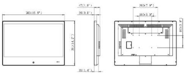
DIMENSIONS OF SMT-2701PVM / SMT-2702PVM (27" PVM)
Unit: mm(inch)

Net Weight: 7.7Kgs /17.1 lbs.
Gross Weight: 10.4Kgs / 23 lbs.
Packing Dimension (L x W x H): 769 x 162 x 608mm / 30.2x 6.3x 23.9 inch
OSD MENU
12
4.1 Main Menu
4.2 Main Adjust
4.3 Color Adjust
4.4 Scan Setting
4.5 Image Adius
4.5 Image Adjust (VGA Only) 4.6 Information
4.5 Information
4.7 Language
4.8 Setup Menu
4.9 Factory Reset
4.10 Audio Control
1
17
MECHANICAL
18
12
12
15
17
13
14
14
15
15
16
16
175.1 Safety
175.2 EMI/EM
186.1 Cabinet
186.2 Dimens
186.3 Dimens
196.4 VESAπ
General
CE INFORMATION
The product must be installed according to the currently valid installation regulations for EMC to guarantee the designed use and to prevent EMC problems.
The device supplied with this manual is according to the EC, EMC Directive, 2014/30/EU & LVD 2014/35/EU
SAFETY PRECAUTIONS
- Do not modify the three-prong grounding type monitor power plug in any way.
- Operate this unit only from the type of power source indicated on the label.
- Do not block or cover ventilation openings on the back or bottom of the monitor cabinet.
- Do not place this monitor near a radiator or heating vent.
- Do not push objects of any kind through cabinet openings. This may result in fire or electrical shock.
- Before adding attachments always ask a service technician to perform routine safety tests to determine that equipment is in safe operating condition. Ground potential tests should be part of the routine safety check made by the service technician.
- Do not place monitor on an unstable cart, stand, or shelf where it may fall and injure personnel or damage equipment.
- Route power cords so that they cannot be walked upon or tripped over. Do not allow anything to rest on the power cord.
- Do not install monitor in wet areas, or where it may be exposed to rain or water. Do not spill liquid of any kind on the unit.
-
Unplug the power cord from the unit before cleaning the display. Use only a damp cloth. Do not use alcohol, spirits, or ammonia to clean the display. DO NOT ATTEMPT TO CLEAN THE INTERIOR OF THIS UNIT- THIS ACTION MUST BE PERFORMED BY THE SERVICE TECHNICIAN AS REQUIRED DURING NORMAL MAINTENANCE.
-
Refer all servicing to qualified service personnel. REMOVAL OF BACK COVER BY UNAUTHORIZED PERSONNEL MAY EXPOSE THE USER TO DANGEROUS VOLTAGES OR OTHER HAZARDS.
-
Unplug the unit immediately and notify the service technician.
A. If liquid has been spilled into the display or the display has been exposed to rain or water.
B. If the unit has been dropped or the cabinet damaged.
C. If fuses continue to blow.
D. If the power cord is damaged or frayed.
E. If a distinct change from normal operation is apparent.
When replacement parts are required, be sure that the service technician uses components specified by the manufacturer which have the same characteristics as the original parts. UNAUTHORIZED SUBSTITUTIONS MAY RESULT IN FIRE, ELECTRICAL SHOCK OR OTHER HAZARDS.
Upon completion of any service or repairs, ask the technician to perform safety checks to determine that the equipment is in safe operating condition.
WARNING: SERIOUS SHOCK HAZARDS EXIST WITHIN THE COVERS OF THIS MONITOR. DO NOT OPEN THE COVERS UNDER ANY CIRCUMSTANCES, THERE ARE NO USER SERVICEABLE COMPONENTS INSIDE
Regulatory Agency
SAFETY APPROVALS
This series design shall meet the standards of the following domestic and foreign agencies: UL : UL 60950-1
cUL: CAN/CSA C22.2 NO. 60950-1-07
EMI/EMS EMISSION APPROVALS
This series design shall meet following EMI/EMS specifications: FCC Compliance: FCC Rules and Regulations, Part 15, subpart B, Class A. CE COMPLIANCE: EN55032 Class A.
EN55024. EN50130-4
OSD menu
FACTORY RESET
Press MENU button to recall PVM Monitor to factory default setting.
AUDIO CONTROL
Press MENU button to enter the sub-menu
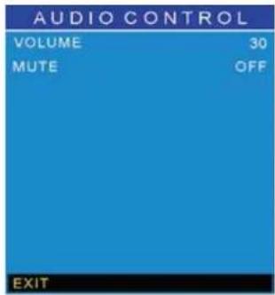
- Press ▼/ ▲button to select an icon
- Press MENU button to confirm the selection.
- Press ▼/ ▲button to adjust the value
- Press MENU button to return
VOLUME – Adjust the PVM Monitor volume.
MUTE - Select Audio MUTE ON/OFF.
BEFORE YOU BEGIN
Read these instructions before installing or operating this product.
Note: This installation should be made by a qualified service person and should conform to local codes.
This manual provides installation and operation information. To use this document, you must have the following minimum qualifications
• A basic knowledge of CCTV systems and components
- A basic knowledge of electrical wiring and low-voltage electrical connections
Intended use
Only use this product for its designated purpose; refer to the product specification and user documentation.
Customer Support
For assistance in installing, operating, maintaining and troubleshooting this product refer to this document and any other documentation provided.
Conventions Used in this Manual
Boldface or button icons highlight command entries. The following WARNING, CAUTION and Note statements identify potential hazards that can occur if the equipment is not handled properly:

*WARNING:
Improper use of this equipment can cause severe bodily injury or equipment damage.

* Caution:
Improper use of this equipment can cause equipment damage.
Note: Notes contain important information about a product or procedure.

This apparatus is manufactured to comply with the radio interference.
A Declaration of Conformity in accordance with the following EU standards has been made. The manufacturer declares that the product supplied with this document is compliant the provisions of the EMC Directive 2014/30/EU, the CE Marking Directive 93/68 EEC and all associated amendments.

All lead-free products offered by the company comply with the requirements of the European law on the Restriction of Hazardous Substances (RoHS) directive: 2011/65/EU, which means our manufacture processes and products are strictly "lead-free" and without the hazardous substances cited in the directive.
The crossed-out wheeled bin mark symbolizes that within the European Union the product must be collected separately at the product end-of-life. This applies to your product and any peripherals marked with this symbol. Do not dispose of these products as unsorted municipal waste.
3 This symbol indicates electrical warnings and cautions.
xx This symbol indicates general warnings and cautions.
General
WARNINGS AND CAUTIONS:
To reduce the risk of fire or electric shock, do not insert any metallic objects through the ventilation grills or other openings on the equipment.
WARNING
This is a Class A product. In a domestic environment this product may cause radio interference in which case the user may be required to take adequate measures.

LANGUAGE
Press MENU button to enter the sub-menu

- Press ▼/ ▲button to select an icon
- Press MENU button to confirm the selection.
SETUP MENU
Press MENU button to enter the sub-menu

- Press ▼: ▲button to select an icon
- Press MENU button to confirm the selection.
- Press ▼: ▲button to adjust the value
- Press MENU button to return OSD TIMEOUT - Adjust the OSD timeout OSD BLENDING - Select OSD blending LOW/MIDDLE/HIGH/OFF BACKLIGHT CONTROL - Select backlight control TIMER/SENSOR/OFF BACKLIGHT TIMER - Set backlight timer 10min\~120min, 10min increment/click LED FLASH - FLASH 1sec(on)/1sec(off) -- OFF/ON LED SWAP - Set LED color GREEN or RED FW, UPDATE (USB) - Plug USB with update FW then select this icon to update PWM FW CAMERA POWER - Press MENU button to return to the main menu EXIT - Press MENU button to return to the main menu
OSD menu
IMAGE ADJUST (VGA ONLY)
Press MENU button to enter the sub-menu

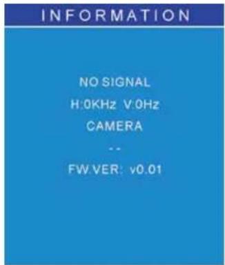
INFORMATION
Press MENU button to enter the sub-menu
14
Functional Specifications
Power Supply
PVM Monitor Power Requirements:
21.5"
Voltage: DC 12V-24V Wide Range
Current: 2.6A max (12Vdc) or 1.3A max (24Vdc)
27"
Voltage: DC 12V-24V Wide Range
Current: 3.6A max (12Vdc) or 1.8A max (24Vdc)
Use only a PSU rated at 12Vdc, with a minimum current rating of 2.6A/3.6A; or 24Vdc, with a minimum current rating of 1.3A/1.8A
D-SUB Input
Analog RGB: 0.707Vrms
Support VESA Standard Timing
HDMI Input - HDMI Compatible Interface
480i/480p/576i/576p
720p / 1080i / 1080p
EDID
This series of displays support EDID (HDMI input only)
Audio Input
Signal Level: 1.0Vrms
Environmental
temperature
- Operating: 0°C to +40°C
● Storage: -20°C to +60°C
Humidity:
- Operating: 10% to 85% (non-condensing)
● Storage: 10% to 95% (non-condensing)
controls & indicators
CONNECTORS

A. DC IN: DC 12\~24V INPUT (DC Jack 5.5mmφ2.5).
B. RJ45: IP Camera Video Output
C. AUDIO IN: Stereo audio input
D. USB: Firmware update
E. HDMI: HDMI input
F. VGA: D-sub 15pin input
COLOR ADJUST
Press MENU button to enter the sub-menu

- Press ▼/ ▲button to select an icon
- Press MENU button to confirm the selection.
- Press ▼/ ▲button to adjust the value
- Press MENU button to return
COLOR TEMP - Select the color temperature USER/
6500K/7500K/9300K
RED - Adjust the RED value under USER setting
GREEN – Adjust the GREEN value under USER setting
BLUE - Adjust the BLUE value under USER setting
EXIT - Press MENU button to return to the main menu
SCAN SETTING
Press MENU button to enter the sub-menu
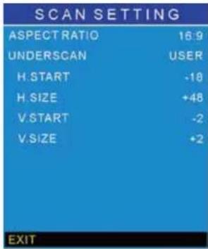
- Press ▼/ ▲button to select an icon
- Press MENU button to confirm the selection.
- Press ▼/ ▲button to adjust the value
- Press MENU button to return
ASPECT RATIO – Select aspect ratio 4:3 or 16:9
UNDERSCAN – Select underscan ON/OFF/USER
H.START - Adjust horizontal start value under USER setting
H.SIZE - Adjust horizontal size value under USER setting
V. START – Adjust vertical start value under USER setting
V.SIZE - Adjust vertical size value under USER setting
EXIT – Press MENU button to return to the main menu
OSD menu
MAIN MENU
Press MENU button to enter the sub-menu

- Main Adjust
• Color Adjust - Scan Setting
- Image Adjust
• Information - Language
- Setup Menu
- Factory Reset
- Audio Control
- Exit
Press ▼/▲ button to select an icon, then press MENU button to confirm the selection.
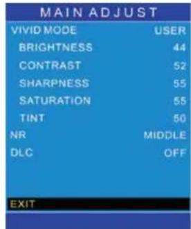
MAIN ADJUST
Press MENU button to enter the sub-menu
- Press ▼/ ▲button to select an icon
- Press MENU button to confirm the selection.
- Press ▼/ ▲button to adjust the value
- Press MENU button to return
VIVID MODE - Select Vivid mode
BRIGHTNESS - Adjust the brightness value
CONTRAST - Adjust the contrast value
SHARPNESS - Adjust the sharpness
SATURATION - Adjust the saturation
NR - Set Noise Reduction level
DLC - Set Dynamic Luminance Control ON/OFF
EXIT - Press MENU button to return to the main menu
CONTROL BUTTON (ON THE BACK)
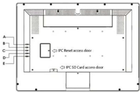
(A) * → Source button
- Press the button to show source menu. Select VGA, HDMI, and CAMERA input.
(B) " ▲" Up button
- Press the buttons to scrolling the cursor to desired function.
- Press the buttons to increase the value of selected function in sub OSD menu.
(C) a ▼v Down button
- Press the buttons to scrolling the cursor to desired function.
- Press the buttons to decrease the value of selected function in sub OSD menu.
(D) "Menu button
- Press the button to show the OSD main menu.
• As a confirmation key during the OSD operation.
(E) * 🔊 Power button
- Press the button to turn ON or turn OFF the monitor.
controls & indicators
LED INDICATION REMOTE CONTROL
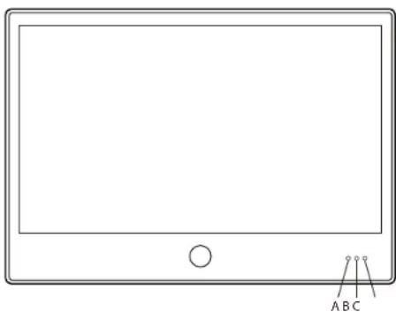
(A) Light sensor: (measures ambient light for auto adjust settings)
(B) IR Receiver: (for remote control)
(C) LED: (Programmable, attention getting LED)

POWER: Monitor Power On/Off.
MUTE: Audio mute
SOURCE: Select input signal

OSD menu navigation
OK: OSD confirm/select
EXIT: Exit the OSD menu
MENU: Access OSD menu
INFO: Displays PVM information
CAMERA: Sets camera as display source
HDMI: Sets HDMI input as display source
VGA: Sets VGA input as display source
LOCK: Activates and deactivates remote key lock
Vol. + : Increase audio volume
Vol. -: Decrease audio volume
Notes:
- The remote control requires 2xAAA batteries. Ensure batteries are inserted in the correct polarity according to the + and - symbols in the battery compartment.
- To avoid damage from possible battery leakage, remove the batteries if you do not plan to use the remote control handset for an extended period of time.
● Batteries should last more than 2 years with normal use.
ACCESSORIES
All of the accessories listed below are included with the PVM.
- 60 Watts 12V power adapter x 1
- US Power Cord x 1
- Remote Control x 1
- DC Terminal x 1
- Cable Clip x 1
- AAA battery x 2
- User's Manual x 1


- LCD PUBLIC VIEW MONITOR
- LCD PUBLIC VIEW MONITOR USER GUIDE
- CONTENTS
- GENERAL
- FUNCTIONAL SPECIFICATIONS
- CONTROLS AND INDICATORS
- VESA MOUNTING
- MECHANICAL
- CABINET
- CE INFORMATION
- SAFETY PRECAUTIONS
- REGULATORY AGENCY
- SAFETY APPROVALS
- EMI/EMS EMISSION APPROVALS
- OSD MENU
- FACTORY RESET
- AUDIO CONTROL
- BEFORE YOU BEGIN
- LANGUAGE
- SETUP MENU
- IMAGE ADJUST (VGA ONLY)
- INFORMATION
- CONTROLS & INDICATORS
- COLOR ADJUST
- SCAN SETTING
- MAIN MENU
- MAIN ADJUST
- CONTROL BUTTON (ON THE BACK)
- NOTES
- ACCESSORIES
Brand : Hanwha
Model : WiseNet SMT-2701PVM
Category : Monitor