
DWS-3160-24TC - Network switch D-LINK - Free user manual and instructions
Find the device manual for free DWS-3160-24TC D-LINK in PDF.


| Product Type | Network Switch |
| Model | DWS-3160-24TC |
| Ports | 20 x 10/100/1000BASE-T Copper + 4 x Combo Copper/SFP (1000BASE-T/SFP) |
| Console Port | 1 x RJ-45 (RS-232 serial) |
| Switching Capacity | 48 Gbps |
| Forwarding Rate | 35.72 Mpps |
| MAC Address Table | 16K entries |
| Jumbo Frame Support | Up to 13 KB |
| VLAN Support | IEEE 802.1Q, up to 4K VLANs (typical) |
| Link Aggregation | IEEE 802.3ad, up to 8 groups |
| Spanning Tree Protocols | 802.1D STP, 802.1w RSTP, 802.1s MSTP |
| Security Features | ACL, 802.1X, SSH, SSL, Port Security, ARP Spoofing Prevention |
| Management | CLI (console/telnet), Web GUI, SNMP v1/v2c/v3, RMON |
| Power Supply (Internal) | 100-240 VAC, 50-60 Hz, 60 W max |
| Redundant Power Supply | Optional DPS-200 (external, 14-pin DC cable) |
| Dimensions (W x D x H) | 440 x 210 x 44 mm (1U) |
| Weight | 2.552 kg |
| Operating Temperature | 0 to 50 °C |
| Humidity | 10% to 90% non-condensing |
| Cooling Fans | 2 fans (side ventilation) |
| SD Card Slot | Yes (supports at least 4 GB) |
| LED Indicators | Power, Console, RPS, Fan Error, SD, Link/Act per port |
| Unified AP Management | Up to 12 APs (default), up to 48 (with license), cluster up to 192 APs |
| Wireless Standards Managed | IEEE 802.11a/b/g/n (via managed APs) |
| Warranty (Hardware) | Limited Lifetime (as long as original owner owns product, min 5 years after discontinuation) |
Frequently Asked Questions - DWS-3160-24TC D-LINK
User questions about DWS-3160-24TC D-LINK
0 question about this device. Answer the ones you know or ask your own.
Ask a new question about this device
Download the instructions for your Network switch in PDF format for free! Find your manual DWS-3160-24TC - D-LINK and take your electronic device back in hand. On this page are published all the documents necessary for the use of your device. DWS-3160-24TC by D-LINK.
USER MANUAL DWS-3160-24TC D-LINK
natural_image
Line drawing of a multi-tiered server rack unit (no text or labels visible)Hardware Installation Guide
Product Model: DWS-3160 Series
Gigabit Ethernet Unified Switch
Release 1.00

Information in this document is subject to change without notice. Reproduction of this document in any manner whatsoever, without the written permission of the D-Link Corporation, is strictly forbidden.
Trademarks used in this text: D-Link and the D-Link logo are trademarks of the D-Link Corporation; Microsoft and Windows are registered trademarks of the Microsoft Corporation.
Other trademarks and trade names may be used in this document to refer to either as the entities claiming the marks and the names or their products. D-Link Corporation disclaims any proprietary interest in trademarks and trade names other than its own.
© 2011 D-Link Corporation. All rights reserved.
November, 2011. P/N 651WS3160005G
FCC Warning
This equipment has been tested and found to comply with the limits for a Class A digital device, pursuant to Part 15 of the FCC Rules. These limits are designed to provide reasonable protection against harmful interference when the equipment is operating in a commercial environment. This equipment generates, uses, and can radiate radio frequency energy and, if not installed and used in accordance with this manual, may cause harmful interference to radio communications. Operation of this equipment in a residential area is likely to cause harmful interference in which case the user will be required to correct the interference at his expense.
CE Mark Warning
This is a Class A product. In a domestic environment, this product may cause radio interference in which case the user may be required to take adequate measures.
Warnung!
Intended Readers ...... v
Typographical Conventions ...... v
Notes, Notices, and Cautions ...... v
Safety Instructions ...... vi
Safety Cautions ...... vi
General Precautions for Rack-Mountable Products ......vii
Protecting Against Electrostatic Discharge......viii
Chapter 1 Introduction....1
Switch Description .... 1
Package Contents....1
Features....2
Ports....3
Front Panel Components 4
LED Indicators 4
Rear Panel Description....5
Side Panel Description 6
Chapter 2 Installation....7
Installation Guidelines....7
Installing the Switch without a Rack 7
Installing the Switch into a Rack....7
Installing SFP transceivers into the SFP Ports 8
Connecting to a Redundant Power Supply 9
Redundant Power Supply, the DPS-200 9
Redundant Power Supply, the DPS-700 10
RPS Rack-Mountable Chassis, the DPS-800 12
RPS Rack-Mountable Chassis, the DPS-900 13
Chapter 3 Switch Connections....15
Switch to an End Node 15
Switch to another Switch 15
Switch to a Server 16
Switch to an Access Point directly 16
Chapter 4 Switch Management....17
Management Options 17
Connecting to the Console Port....17
Connecting to the Switch for the first time....19
Creating a User Account 20
Configuring the IP Address....20
Connecting using SNMP 22
Traps....23
Management Information Base (MIB) 23
Connecting using the Web User Interface 24
Logging onto the Web Manager 24
Areas of the User Interface....25
Chapter 5 D-Link Unified Access System....26
D-Link Unified Access System Components 26
D-Link Unified Switch 26
D-Link Access Point 26
WLAN Visualization 27
D-Link Unified Access System Topology....28
Single Unified Switch Deployment....28
Peer Unified Switch Deployment....28
Chapter 6 Appendix Section....30
Appendix A – Technical Specifications....30
General 30
Physical and Environmental 30
Performance 31
LED Indicators 31
Port Functions....32
Wireless Functions 33
Appendix B – Cables and Connectors....35
Ethernet Cable....35
Console Cable 36
Redundant Power Supply (RPS) Cable 37
Appendix C – Module Specifications and Cable Lengths....39
Warranties & Support......40
Intended Readers
Intended Readers
Typographical Conventions
Notes, Notices, and Cautions
Safety Instructions
General Precautions for Rack-Mountable Products
Protecting Against Electrostatic Discharge
The DWS-3160 Series Hardware Installation Guide contains detailed information about the hardware specifications of a Switch in this series. It also contains brief information on how to configure and manage a Switch in this series. This manual is intended for advanced level users that are familiar with network management concepts and terminology. For all practical reasons all the Switches in this series will simply be referred to as the Switch throughout this manual. All example screenshots are taken from the DWS-3160-24PC Switch.
Typographical Conventions
| Convention Description | |
| [] | This convention is generally used in CLI commands. Square brackets indicate an optional entry. For example: [copy | paste] means that optionally you can type copy or you can type paste. Do not type the brackets. |
| Bold font | This font is generally used to put emphasis on a key subject in a sentence throughout this manual. This font is also used to represent the physical CLI command used when explaining a topic. |
| Boldface Typewriter Font | This font is used to indicate CLI command examples used in this document. |
| Initial capital letter | The use of initial capital letters indicates that a referral to a specific name was made. This will be seen a lot when referring to protocols, standards, keyboard keys, and when we refer to the ‘Switch’ as a generic name for all switches with in the series. For example: Click Enter. |
| Menu Name > Menu Option | This convention indicates the referral to a menu structure found in the Web User Interface of this Switch. For example: Device > Port > Port Properties means the Port Properties menu option under the Port menu option that is located under the Device menu. |
Notes, Notices, and Cautions

A NOTE indicates that the reader must pay attention to this information in order to make better use of the device.

A NOTICE indicates that the reader must observe the result when a certain action was taken.

A CAUTION indicates that the reader must pay serious attention to this information as negligence will probably result in potential property damage, personal injury, or even death.
Safety Instructions
Please pay careful attention to the following safety guidelines to ensure your own personal safety and to help protect your system from potential damage.
Safety Cautions
To greatly reduce the risk of physical injury, electrical shock, fire, and damage to equipment, observe the following precautions.
Observe and follow service markings.
- Do not attempt to service any product, except when it is explained in the system's documentation.
- Opening or removing covers that are marked with this (△) symbol may expose the user to electrical shock.
- Only a trained service technician should service components inside these compartments.
If any of the following conditions occur, unplug the product from the electrical outlet immediately and replace the part or contact your trained service provider:
- Damage to the power cable, extension cable, or plug.
- An object has fallen into the product.
- The product has been exposed to water.
- The product has been dropped or damaged.
• The product does not operate correctly when the operating instructions are correctly followed.
General safety cautions:
- Keep the system away from radiators and heat sources. Also, do not block cooling vents.
- Do not spill food or liquids on system components, and never operate the product in a wet environment. If the system gets wet contact your trained service provider.
- Do not push any objects into the openings of the system. Doing so can cause fire or electric shock by shorting out interior components.
- Only use this product with approved equipment.
- Allow the product to cool before removing the cover or touching internal components.
- Operate the product only from the type of external power source indicated on the electrical ratings label. If unsure of the type of power source required, consult your service provider or local power company.
- Be sure that attached devices are electrically rated to operate with the power available in your location.
- Use only approved power cable(s). If you have not been provided with a power cable for your system or for any AC-powered option intended for your system, purchase a power cable that is approved for use in your country. The power cable must be rated for the product and for the voltage and current marked on the product's electrical ratings label. The voltage and current rating of the cable should be greater than the ratings marked on the product.
- To help prevent electric shock, plug the system and peripheral power cables into properly grounded electrical outlets. These cables are equipped with three-prong plugs to help ensure proper grounding. Do not use adapter plugs or remove the grounding prong from a cable. If using an extension cable is necessary, use a 3-wire cable with properly grounded plugs.
- Observe the extension cable and power strip ratings. Make sure that the total ampere rating of all products plugged into the extension cable or power strip does not exceed 80 percent of the ampere ratings limit for the extension cable or power strip.
- To help protect the system from sudden, transient increases and decreases in electrical power, use a surge suppressor, line conditioner, or uninterruptible power supply (UPS).
- Position system cables and power cables carefully. Route cables so that they cannot be stepped on or tripped over. Be sure that nothing rests on any cables.
- Do not modify power cables or plugs. Consult a licensed electrician or your power company for site modifications. Always follow your local or national wiring rules.
When connecting or disconnecting power to and from hot-pluggable power supplies, observe the following guidelines:
• Install the power supply before connecting the power cable to the power supply.
- Unplug the power cable before removing the power supply.
- If the system has multiple sources of power, disconnect power from the system by unplugging all power cables from the power supplies.
- Move products with care and ensure that all casters and stabilizers are firmly connected to the system. Avoid sudden stops and uneven surfaces.
To help avoid damage to the system, be sure that the voltage selection switch, on the power supply, is set to match the power available at the switch's location:
- 115V/60Hz is used mostly in North and South America as well as Far Eastern countries like as South Korea and Taiwan
• 100V/50Hz is used mostly in Eastern Japan and 100V/60Hz in Western Japan
• 230V/50Hz is used mostly in Europe, the Middle East, Africa and the Far East
General Precautions for Rack-Mountable Products
Please pay careful attention to the following precautions concerning rack stability and safety. Systems are considered to be components in a rack. Thus, a component refers to any system, as well as to various peripherals or supporting hardware.

CAUTION: Installing systems in a rack without the front and side stabilizers installed could cause the rack to tip over, potentially resulting in serious injury. After installing system/components in a rack, never pull more than one component out of the rack on its slide assemblies at one time. The weight of more than one extended component could cause the rack to tip over and may result in serious injury.
- Before working on the rack, make sure that the stabilizers are secured to the rack, extended to the floor, and that the full weight of the rack rests on the floor. Install front and side stabilizers on a single rack or front stabilizers for joined multiple racks before working on the rack.
• Always load the rack from the bottom up, and load the heaviest item in the rack first.
• Make sure that the rack is level and stable before extending a component from the rack. - Use caution when pressing the component rail release latches and sliding a component into or out of a rack; the slide rails can pinch your fingers.
- After a component is inserted into the rack, carefully extend the rail into a locking position, and then slide the component into the rack.
- Do not overload the AC supply branch circuit that provides power to the rack. The total rack load should not exceed 80 percent of the branch circuit rating.
- Ensure that proper airflow is provided to components in the rack.
- Do not step on or stand on any component when servicing other components in a rack.

CAUTION: Never defeat the ground conductor or operate the equipment in the absence of a suitably installed ground conductor. Contact the appropriate electrical inspection authority or an electrician if uncertain that suitable grounding is available.

CAUTION: The system chassis must be positively grounded to the rack cabinet frame. Do not attempt to connect power to the system until grounding cables are connected. Completed power and safety ground wiring must be inspected by a qualified electrical inspector. An energy hazard will exist if the safety ground cable is omitted or disconnected.
Protecting Against Electrostatic Discharge
Static electricity can harm delicate components inside the system. To prevent static damage, discharge static electricity from your body before touching any of the electronic components, such as the microprocessor. This can be done by periodically touching an unpainted metal surface on the chassis.
The following steps can also be taken prevent damage from electrostatic discharge (ESD):
- When unpacking a static-sensitive component from its shipping carton, do not remove the component from the antistatic packing material until ready to install the component in the system. Just before unwrapping the antistatic packaging, be sure to discharge static electricity from your body.
- When transporting a sensitive component, first place it in an antistatic container or packaging.
- Handle all sensitive components in a static-safe area. If possible, use antistatic floor pads, workbench pads and an antistatic grounding strap.
Chapter 1 Introduction
Switch Description
Package Contents
Features
Ports
Front Panel Components
LED Indicators
Rear Panel Description
Side Panel Description
Switch Description
The DWS-3160 Series Gigabit Ethernet Unified Switch is specifically tailored for a small and remote office environment and fulfills the growing demand of wireless unified switches in this segment. This series provides a performance optimized, cost effective solution for small and remote offices as well as small to medium sized enterprise wireless network deployments.
With the default D-Link License Management Service (DLMS) agreement, this Switch can manage up to 12 unified Access Points. After an optional upgrade of the license agreement, purchased from D-Link, this Switch can manage up to 48 unified Access Points per unified Switch. The most powerful feature of this Switch is that up to 4 Switches can form a cluster to manage up to 192 unified Access Points centrally with a single IP address.
This cost effective Gigabit Switch provides an affordable solution for Administrators to upgrade their networks to high speed Gigabit connections. The advanced Access Control Lists (ACLs) and User Authentication functions on the Switch extends network security coverage from the Core part of the network to the Edge parts. A unique D-Link Safeguard Engine protects this Switch from outside networking threats and thereby increasing overall reliability, serviceability, and availability.
The Switch is equipped with Copper ports (10/100/1000Mbps) and SFP ports (10/1000Mbps) that can be used to attach various networking devices to the network like Computers, Notebooks, Print Servers, Network Attached Storage devices, IP Cameras, VoIP PBX devices, and other Switches. The Small Form Factor Portable (SFP) combo ports can be used together with fiber-optical transceivers in order to connect various other networking devices, using a fiber-optic connection, to the network at Gigabit Ethernet speeds over great distances.
All the copper ports the DWS-3160-24PC Switch also offers Power over Ethernet (PoE) for a variety of uses. On the DWS-3160-24PC Switch, each Gigabit port supports the standards IEEE 802.3af and IEEE 802.3at Power over Ethernet that allows PoE devices like Access Points (supporting the standard IEEE 802.11n), VoIP phones and IP Cameras to connect to the Switch and receive power from it at the same time. This provides ease of installation and placement, as well as lesser power points needed for the devices connected to the Switch.
Package Contents
Open the shipping carton of the Switch and carefully unpack its contents. The carton should contain the following items:
• One DWS-3160 Series Switch.
• One Quick Installation Guide.
• One AC power cord.
• One RJ-45 to RS-232 console cable.
• One rack mounting kit (two brackets and screws).
- Four rubber feet with adhesive backing.
• One CD containing the Web UI Reference Guide, CLI Reference Guide, and D-View module.
If any item is missing or damaged, please contact your local D-Link reseller for replacement.
Features
This Switch series is action packed with an abundance of networking features that span inside and outside of the traditional Layer 2 framework making it truly a Layer 2+ Switch. The list below highlights the significant protocols and features supported by this Switch.
Local Area Networking (LAN) features that can be found on this Switch series are:
• Virtual Stacking otherwise known as Clustering.
- Flow Control with Head-Of-Line blocking prevention.
- Internet Group Management Protocol (IGMP) Snooping Versions 1, 2, and 3.
- Multicast Listener Discovery (MLD) Snooping Version 1 and 2.
• BPDU Attack Protection.
- Link Aggregation (IEEE 802.3ad).
• Link Layer Discovery Protocol (LLDP).
- Layer 2 Protocol Tunneling (L2PT).
• Virtual LAN (VLAN) using the IEEE 802.1Q protocol.
• Voice VLAN and Guest VLAN.
• Asymmetric VLAN and ISM VLAN.
- Static Routing.
• Quality Of Service (QoS)
• Class of Service (CoS).
• Layer 3, Control Packet Filtering.
• CPU Interface Filtering (Software ACL).
- Secure Sockets Layer (SSL).
• Storm Control (Unicast/Broadcast/Multicast).
• D-Link Safeguard Engine.
- ARP Spoofing Prevention.
• NetBIOS/NetBEUI Filtering.
- Proxy ARP.
- IEEE 802.1X Network Access Control.
• MAC-based Access Control (MAC).
- Microsoft ^ Network Access Protection (NAP).
- User Account Privileges.
- Authentication Database Failover Enhancement.
• Web-based GUI Management.
- Telnet Server/Client and TFTP Client.
- SNMP Traps.
• RMON Version 1 and 2.
• DHCP Auto-configuration, Client and Relay.
- CPU Monitoring.
• IPv6 Neighbor Discovery (ND).
- Simple Mail Transfer Protocol (SMTP).
- Cable Diagnostics.
- Power Saving.
• Wi-Fi Multimedia Power Save (WMM-PS).
• D-Link License Management System (DLMS).
• A 16K MAC Address Table.
• Jumbo Frame of up to 13Kb.
- Internet Group Management Protocol (IGMP) Authentication.
- Spanning Tree Protocols like 802.1D STP, 802.1w RSTP, and 802.1s MSTP.
• D-Link Loopback Detection Version 4.0.3
- Port Mirroring that includes RSPAN.
• Network Load Balancing (NLB).
• PPPoE Circuit-ID Tag Insertion.
- VLAN Grouping.
• Port-based, MAC-based, and Protocol-based VLAN.
• VLAN Trunking and Private VLAN.
• Virtual Router Redundancy Protocol (VRRP).
- Queue Handling (Strict and Weighted Round Robin).
- Bandwidth Control.
- Access Control Lists (ACLs), Ingress and Egress ACLs.
- Secure Shell (SSH).
- Port Security.
- Traffic Segmentation
- DHCP Server Screening.
• Filter Database (FDB) Security.
- DoS Prevention.
- Access Authentication Control.
- Captive Portal.
- Compound Authentication.
• RADIUS Accounting and Authentication.
- Trusted Hosts.
- Command Logging.
- Command Line Interface (CLI) Management.
- Simple Network Management Protocol (SNMP).
- Trap/Alarm/Log Severity Control.
- sFLOW.
- Multiple Image and Configuration support.
- Password Encryption and Recovery.
- Internet Control Message Protocol (ICMP).
- SD Card Management.
- Ethernet Link OAM (IEEE 802.3ah).
• Time-based Power-over-Ethernet (PoE).
• Intelligent Green Network (D-Link Green 3.0).
• TACACS+ Authentication
- Management Information Base (MIBs) for MIBII, Bridge MIB, SNMPv2 MIB, RMON MIB, RMONv2 MIB, Ether-like MIB, 802.1p MIB, IF MIB, RADIUS Authentication Client MIB, RADIUS Accounting Client MIB, Ping and Traceroute MIB, Private MIB, IPv6 MIB, IP MIB, TCP MIB, Zone Defense MIB, UDP, ICMP, ARP, Entity MIB, and TCP/IP-based Internet.
Wireless Local Area Networking (WLAN) features that can be found on this Switch series are:
- Switch and Access Point Discovery.
- Intra-Switch Roaming
• Layer 2 and Layer 3 Roaming. - MSS Reduction.
• AP to AP Tunneling. - Multiple SSIDs per Switch.
• Automatic AP transmit output power adjustment. - Load Balancing.
• AP Auto-discovery.
• AP, Client and Ad-hoc Client monitoring. - Centralized RF/Security policy management.
- Unified AP Support (DWL-8600AP, DWL-3600AP and DWL-6600AP).
• SVP (Spectralink Voice Protocol).
• Wireless Security Modes like WEP, WPA, and WPA2.
• Wireless Intrusion Detection System (WIDS). - Rogue AP Mitigation.
-
Station Isolation.
-
Fast Roaming.
- Inter-Switch Roaming
- Tunnel Protocols like D-Link Wireless AP Protocol (DWAPP) and CAPWAP-like protocol.
- Tunnel (L3 Tunneling) and non-Tunnel (VLAN Forwarding) modes.
• Multiple ESSIDs per Access Point.
• Automatic AP RF channel adjustment.
• RF Self-healing around Failed AP. - AP Software version Auto-detection and Central Firmware dispatch.
- Remote AP rebooting.
- AP Authentication.
- Visualized AP Management Tool.
• Wireless Multimedia (WMM). - Wireless Standards like IEEE 802.11a, 802.11b, 802.11g, 802.11d, 802.11h, 802.11n.
- IEEE 802.1X EAP types like EAP-MD5, EAP-TLS, EAP-TTLS, EAP-FAST, EAP-SIM, PEAP-GTC, PEAP-TLS, and PEAP-MS-CHAPv2.
- Rogue AP Detection.
- Captive Portal.
Ports
In the DWS-3160 Series there are 2 Switches. They are:
- The DWS-3160-24TC that includes 20 Copper ports (10/100/1000BASE-T) and 4 Combo Copper/SFP ports (1000BASE-T/SFP), Layer 2+, Unified Switch.
- The DWS-3160-24PC that includes 20 Copper PoE ports (10/100/1000BASE-T) and 4 Combo Copper/SFP PoE ports (1000BASE-T/SFP), Layer 2+, Unified Switch.
All the Switches, in the Series, are equipped with:
- One RJ-45 Console port (used to connect to the Command Line Interface (CLI) of the Switch). This port uses a special console cable (included with the packing) with a DB9 interface to connect the Switch to a PC.
• One Redundant Power Supply (RPS) outlet for optional external RPS.

NOTE: For customers interested in D-View, D-Link Corporation's proprietary SNMP management software, go to http://dview.dlink.com.tw/ and download the software and manual.
Front Panel Components
The Front panel of the Switch consists of a Console port, LED indicators, Copper (10/100/1000Mbps) ports, SFP (10/1000Mbps) ports and an SD Card slot.

Figure 1-1. Front panel view of the DWS-3160-24TC

Figure 1-2. Front panel view of the DWS-3160-24PC
A separate table below describes LED indicators in more detail.
LED Indicators
On the Switch's front panel we'll find the following LED indicators: Power, Console, RPS, Fan, and SD. For each Copper/SFP port, also found on the front panel, there is a Link/Act light. The DWS-3160-24PC Switch is also equipped with an additional PoE light, to indicate whether the ports are running in the Power-over-Ethernet mode or not.
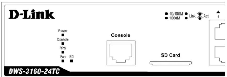
Figure 1-3. LED indicators for the DWS-3160-24TC
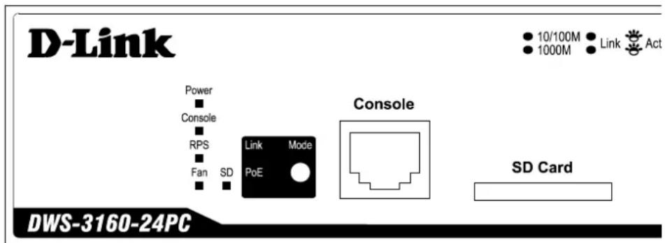
Figure 1-4. LED indicators for the DWS-3160-24PC
| LED Description | |
| Power | This LED will light solid green after the Switch has been powered on successfully. This LED will be off when the Switch is no longer receiving power (i.e. powered off). |
| Console | This LED will blink green during the Power-On Self Test (POST). This LED will light solid green when a user is logged in through the console port. This LED will be off after the POST finished successfully and no user is connected to the console port. |
| RPS | This LED will light solid green if the Redundant Powers Supply is in use. This LED will blink green when the Switch detects that the RPS is connected. This LED will be off when the RPS is not in use. |
| Fan | This LED will blink red when a fan fails. This LED will be off when all the fans are working properly. |
| SD | This LED will light solid green if a Secure Digital (SD) card is plugged in. This LED will blink green when the Switch is reading or writing data to and from the SD card. This LED will be off when no SD card is plugged into the SD port. This LED will light solid red when an SD card failure has been detected. |
| Link/Act LEDs | This LED will light solid green when there is a secure connection to a 1000Mbps Ethernet device at any of the ports. This LED will light solid orange when there is a secure connection to a 10/100Mbps Ethernet device at any of the ports. This LED will blink green when a 1000Mbps port is active, or blink orange when a 10/100Mbps port is active. This LED will be off when there is no link or activity. |
| PoE LED Mode (DWS-3160-24PC Only) | This LED will light solid green when the port is feeding power to the PoE devices plugged in. This LED will light solid orange when the port is in an error condition state. This LED will be off when the port is not supplying power to the device plugged in. After the pressing the 'Mode' button, only the port LEDs, that feed power, will be lit. |
Rear Panel Description
The Rear panel of the Switch consists of a power connector and an outlet for an external redundant power supply.

Figure 1-5. Rear panel view of the DWS-3160-24TC

Figure 1-6. Rear panel view of the DWS-3160-24PC
Connect the one end of the power cord supplied to the power connector and the other end into a properly grounded electrical outlet. The Switch will automatically adjust the power setting to adapt to any voltage supply in the range from
100\~240VAC at 50\~60Hz.
In addition, an optional external Redundant Power Supply (DPS-200 for the DWS-3124-24TC and DPS-700 for the DWS-3124-24PC) can be plugged into the connector displayed above. When the internal power fails, this optional external RPS will take over all the power immediately and automatically.
In the event that a power failure might occur in the environment and no UPS is used, as a precaution, unplug the power cord from the Switch. After the return of power, you can plug the power cord back into the Switch's power connector.
Side Panel Description
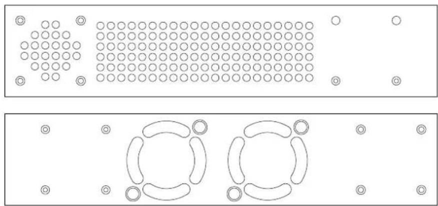
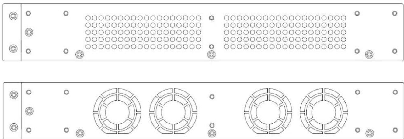
The Side panel of the Switch consists out of heat and fan vents that are used to dissipate heat. Do not block these openings. Leave at least 4 inches of space at the rear and sides of the Switch for proper ventilation. Be reminded that without proper heat dissipation and air circulation, system components might overheat, which could lead to system failure or even severely damage components.
natural_image
Top-down and side-view diagram of a device layout with circular components and grid patterns (no text or symbols)Figure 1-7. Side panels of the DWS-3160-24TC
natural_image
Technical diagram of a server rack with four circular components and mounting holes (no text or labels)Figure 1-8. Side panels of the DWS-3160-24PC
Chapter 2 Installation
Installation Guidelines
Connecting to a Redundant Power Supply
Installation Guidelines
This section will discuss the hardware installation guidelines that the user must follow in order to properly and safely install this Switch into the appropriate environment.
- Visually inspect the power cord and see that it is fully secured to both the power connector, on the Switch, and the electrical outlet, that supplies power.
- Install the Switch in a fairly cool and dry place within the acceptable temperature and humidity operating ranges.
- Install the Switch in a site free from strong electromagnetic field generators such as motors, vibration, dust, and direct exposure to sunlight.
Installing the Switch without a Rack
This section is used to guide the user through installing the Switch in an area other than a switch rack. Attach the rubber feet included to the bottom of the Switch. Take note that there should be marked blocks on the bottom of the Switch to indicate where to attach the rubber feet. These marking are usually found at each bottom corner of the device. The rubber feet cushion the Switch, protecting the casing from scratches and preventing it from scratching other surfaces.
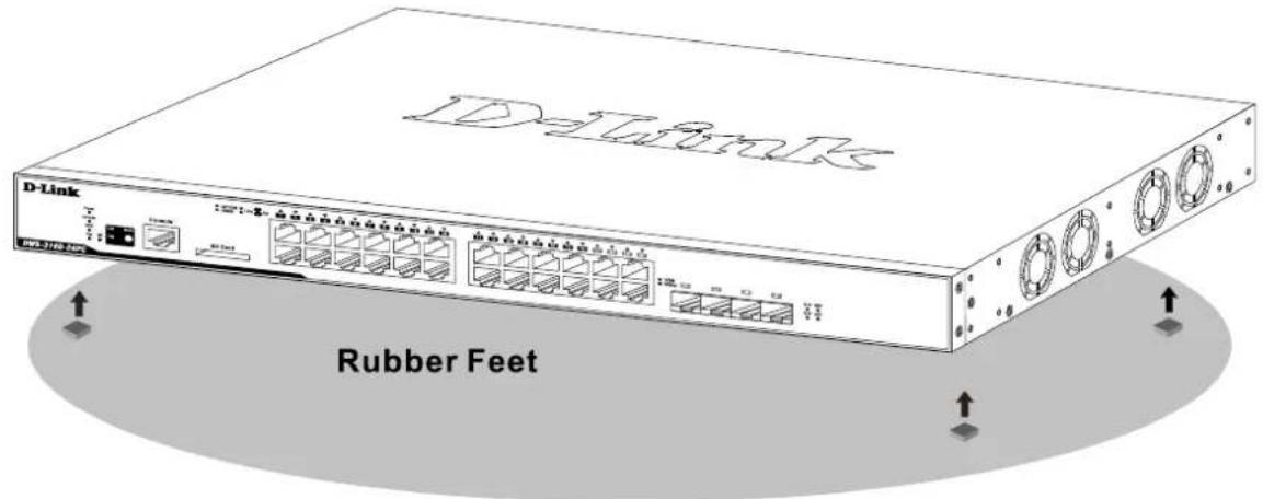
Figure 2-1. Prepare the Switch for installation on a desktop or shelf
Install the Switch on a sturdy, level surface that can support the weight of the Switch (see the Appendix section for the weight specifications of each Switch). Do not place any heavy objects on the Switch. The power outlet should be within 1.82 meters (6 feet) of the Switch.
Make sure that there is proper heat dissipation from and adequate ventilation around the Switch. Leave at least 10 cm (4 inches) of space at the front and rear of the Switch for ventilation.
Installing the Switch into a Rack
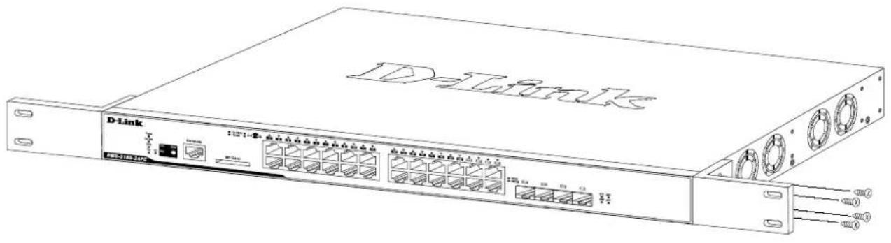
This section is used to guide the user through installing the Switch into a switch rack. The Switch can be mounted in a standard 19"(1U) rack using the provided mounting brackets. Use the following diagram as a guide.
natural_image
Line drawing of a D-Link network switch device with ports and connectors (no text or symbols on the main body)Figure 2-2. Fasten mounting brackets on the Switch
Fasten the mounting brackets supplied to the sides of the Switch using the screws provided. With the brackets attached securely, the Switch can be mounted in a standard rack, as shown below.
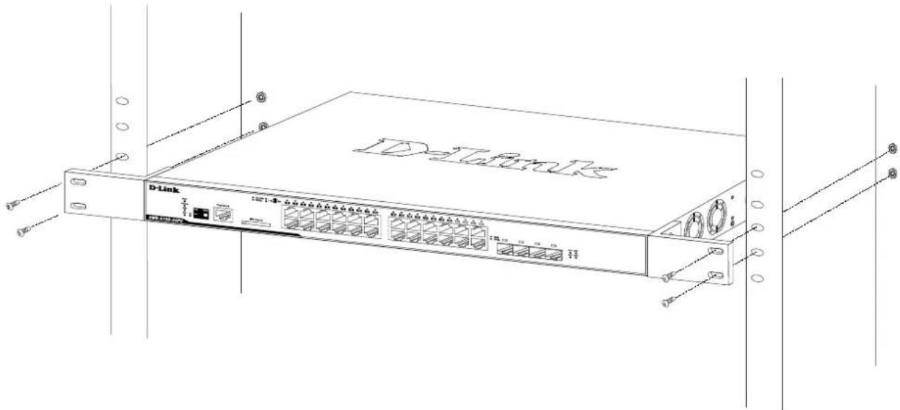
Figure 2-3. Installing the Switch in a rack
Make sure that there is adequate space around the Switch to allow for proper air flow, ventilation, and cooling.
Installing SFP transceivers into the SFP Ports
The Switch is equipped with small form-factor pluggable (SFP) ports (otherwise known as Mini-GBIC ports) that can be used to connect various other networking devices to this Switch that do not support the standard copper wiring connection. These ports are generally used to connect this Switch to networking devices that can only be accessed via an optical fiber connection and is normally used for a connection that spans greater distances. The maximum distance that the copper wiring connection can reach is 100 meters. Fiber optic connections can span over several kilometers.
The figure below illustrates how to properly insert SFP transceivers into the Switch's SFP ports.
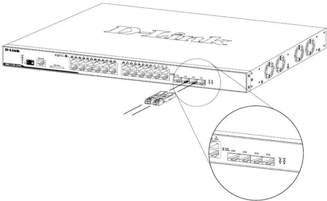
Figure 2-4. Inserting SFP transceivers into the Switch's SFP ports
A complete list of SFP transceivers, compatible with this Switch, can be found in the Appendix section, at the end of this document.
Connecting to a Redundant Power Supply
This Switch can be connected to the Redundant Power Supply (RPS) using either a 14-pin DC power cable or a 22-pin DC power cable. A standard, three-pronged AC power cable connects to the redundant power supply and the main power source to provide power to the RPS. The external redundant power supply is only used when the internal power supply fails. After the internal power supply fails, the external RPS will immediately take over the power supplying duties to the Switch automatically.
Please note that every Switch within this series will make use of a specific RPS.
The DWS-3160-24TC must be used together with the DPS-200 Redundant Power Supply or an equivalent RPS. The DWS-3160-24PC must be used together with the DPS-700 Redundant Power Supply or an equivalent RPS.
Redundant Power Supply, the DPS-200
The D-Link, DPS-200, External Redundant Power Supply, provides a backup power solution to the DWS-3160-24TC Switch in the event that the Internal Power Supply fails. The DPS-200 is a standalone, low-cost, simple solution that can prevent the Switch from shutting down when the Internal Power Supply fails. This option is imperative when the availability of this Switch on the network is of high importance.
REAR PANEL OF DWS-3160-24TC
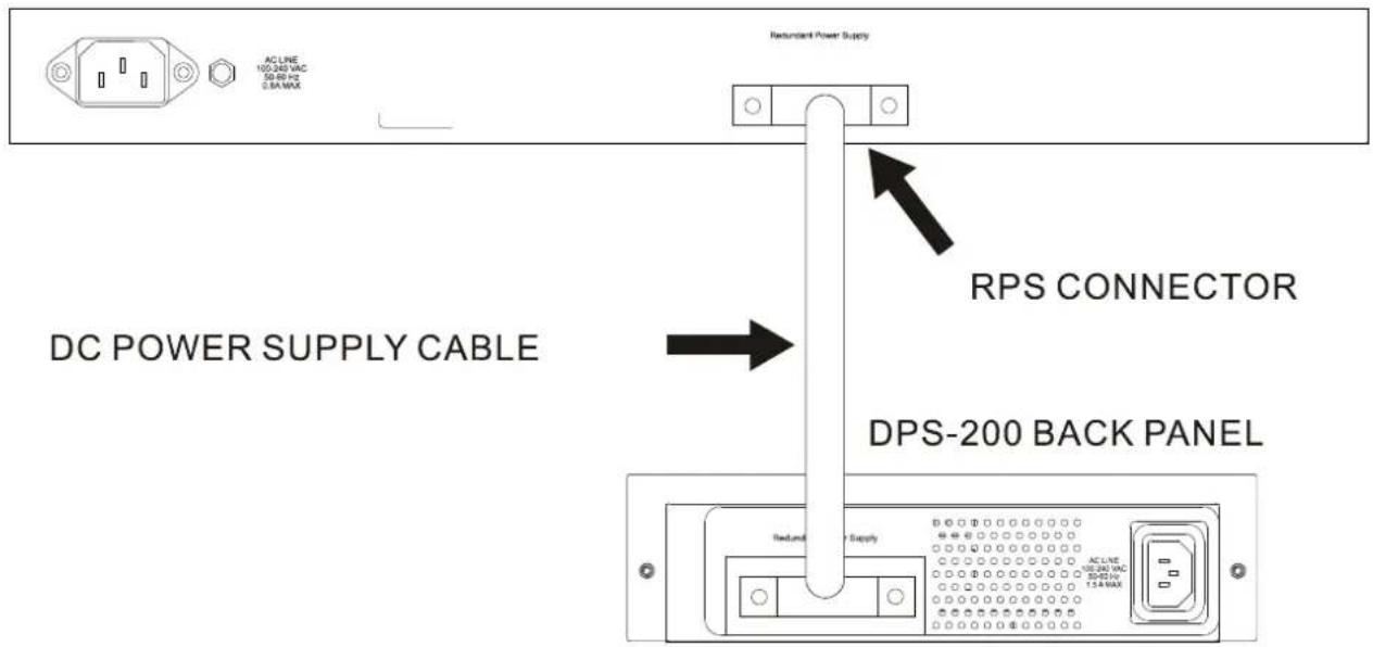
Figure 2-5. Connecting the DWS-3160-24TC to the DPS-200
To connect the DPS-200 to the Switch for the first time, follow these steps:
- Disconnect the power cable from the power connector of the Switch.
- Interlink the RPS ports of the Switch and the DPS-200 by using the 14-pin DC power cable, supplied with the RPS.
- Interlink the Power connector, of the DPS-200, and the grounded electrical outlet by using a standard AC power cable. A green LED on the front of the DPS-200 will illuminate to indicate a successful connection.
- Reconnect the power cable to the power connector of the Switch.
- No software configuration is needed for this installation.

CAUTION: Do NOT use the DWS-3160-24TC Switch with any Redundant Power System other than the DPS-200.
Redundant Power Supply, the DPS-700
The D-Link, DPS-700, External Redundant Power Supply, provides a backup power solution to the DWS-3160-24PC Switch in the event that the Internal Power Supply fails. The DPS-700 is a standalone, low-cost, simple solution that can prevent the Switch from shutting down when the Internal Power Supply fails. This option is imperative when the availability of this Switch on the network is of high importance.
REAR PANEL OF DWS-3160-24PC
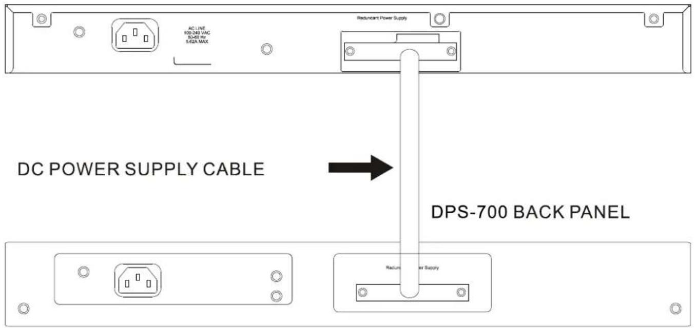
Figure 2-6. Connecting the DWS-3160-24PC to the DPS-700
To connect the DPS-700 to the Switch for the first time, follow these steps:
- Disconnect the power cable from the power connector of the Switch.
- Interlink the RPS ports of the Switch and the DPS-700 by using the 22-pin DC power cable, supplied with the RPS.
- Interlink the Power connector, of the DPS-700, and the grounded electrical outlet by using a standard AC power cable. A green LED on the front of the DPS-700 will illuminate to indicate a successful connection.
- Reconnect the power cable to the power connector of the Switch.
- No software configuration is needed for this installation.

CAUTION: Do NOT use the DWS-3160-24PC Switch with any Redundant Power System other than the DPS-700.
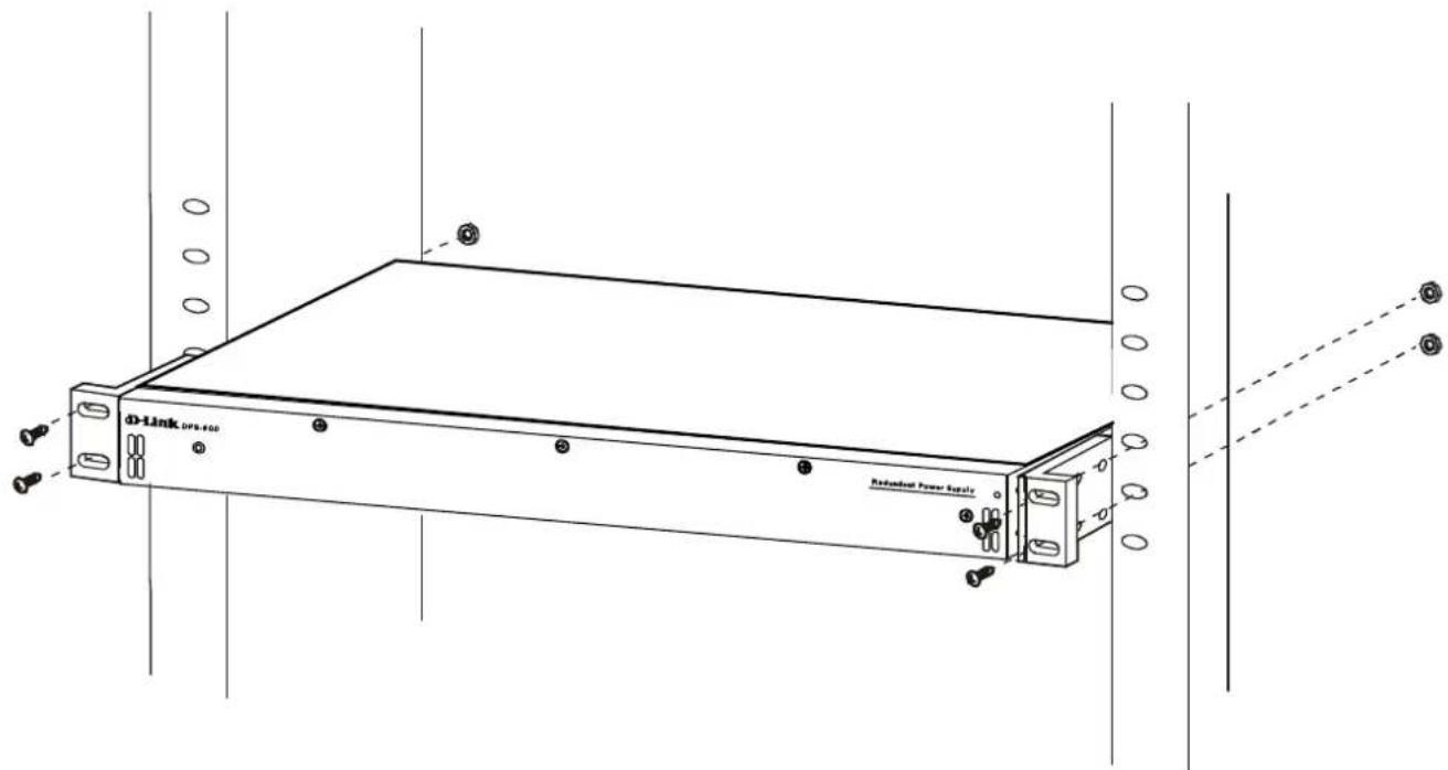
Figure 2-7. Front view of the DPS-700
RPS Rack-Mountable Chassis, the DPS-800
Because of the small size of the DPS-200, the DPS-800 can be used to house and mount the DPS-200 into a switch rack. The DPS-800 is a standard-size rack mount (1U) designed to hold up to two DPS-200 redundant power supplies. Using this rack mount chassis, will allow the user to save space when deploying the DPS-200 RPS's into a switch rack.
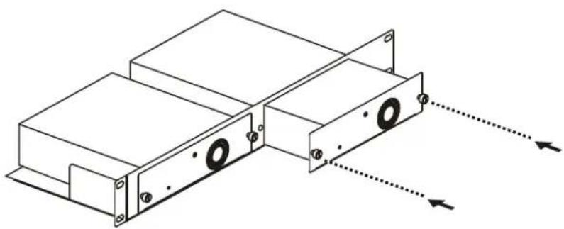
natural_image
Technical line drawing of a mechanical assembly with mounting flanges and housing (no text or symbols)Figure 2-8. Installing the DPS-200 in the DPS-800
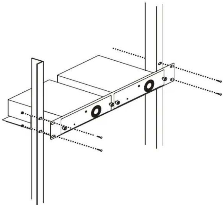
The RPS can be mounted in a standard 19" rack. Use the following diagram to guide you.
natural_image
Technical line drawing of a mechanical assembly with mounting holes and structural supports (no text or symbols)Figure 2-9. Installing the DPS-800 in an Equipment Rack

NOTE: The DPS-800 is NOT equipped with any power supplies on its own. This is a 2-slot, rack-mountable chassis.
RPS Rack-Mountable Chassis, the DPS-900
Because of the small size of the DPS-200, the DPS-900 can be used to house and mount the DPS-200 into a switch rack. The DPS-900 is a standard-size rack mount (5U) designed to hold up to eight DPS-200 redundant power supplies. Using this rack mount chassis, will allow the user to save space when deploying the DPS-200 RPS's into a switch rack.
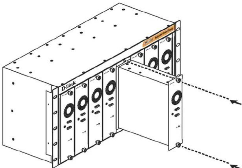
Figure 2-10. Inserting the DPS-200 into the DPS-900
The RPS can be mounted in a standard 19" rack. Use the following diagram to guide you.
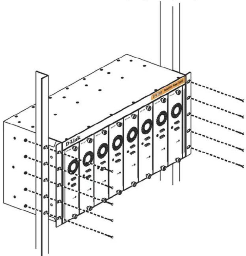
Figure 2-11. Installing the DPS-900 into the equipment rack

NOTE: The DPS-900 is NOT equipped with any power supplies on its own. This is an 8-slot, rack-mountable chassis.
Chapter 3 Switch Connections
Switch to an End Node
Switch to another Switch
Switch to a Server
Switch to an Access Point directly
Switch to an End Node
End node is a generic name for edge networking devices that will be connected to this Switch. Typical examples of end nodes are Personal Computers (PCs), Notebooks, Access Points, Print Servers, VoIP Phones and more. Each end node will be outfitted with a 10/100/1000Mbps, RJ-45, networking port. Normally end nodes will connect to this Switch by using a standard twisted-pair, UTP/STP, network cable. Any one of the networking ports, found on this Switch, can be used to connect to an end node. After a successful connection, the corresponding Link/Act light will illuminate and blink to indicate that packet activity is taking place on that port.
The diagram below display a typical end node connected to the Switch.
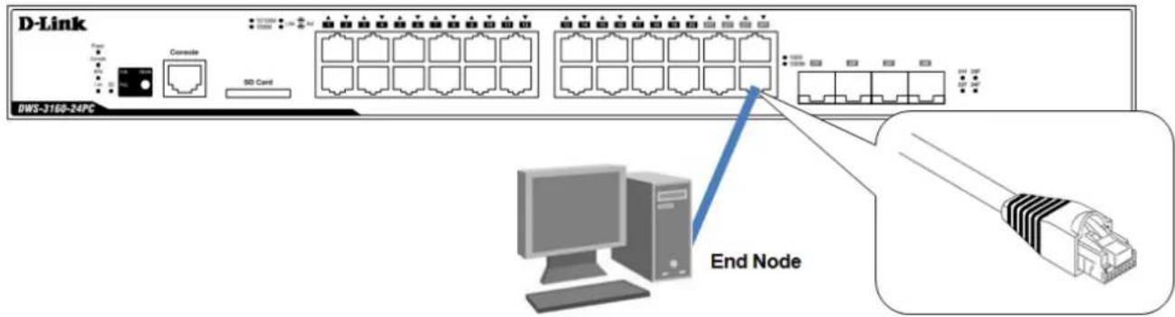
Figure 3-1. Connecting the Switch to an end node
Switch to another Switch
Another popular configuration is to connect this Switch to another Switch or Hub. This network typography is considered when one Switch does not have enough ports to cater for all the end nodes in the network. There is a great deal of flexibility in the type of cabling that can be used to interlink switches. The copper ports support cables like Categories 3, 4, 5, and 5e running on standards like 10BASE-T, 100BASE-TX, and 1000BASE-T. Two or more Switches can also be interlinked using fiber-optic cables via the Switch's SFP ports.
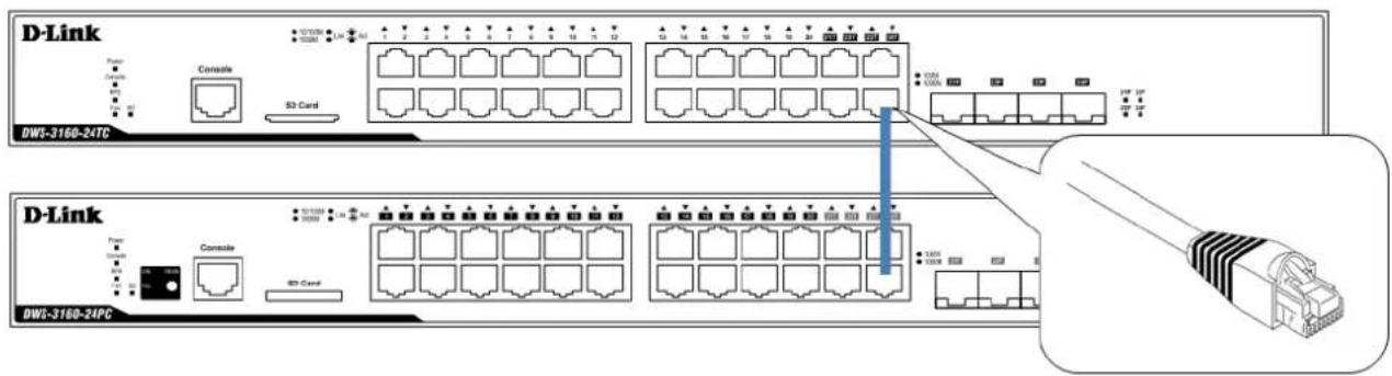
Figure 3-2. Connecting a Switch to another switch
Switch to a Server
When configuring a network, users will most likely have to add a Server or two to this Switch. Generally, any port on this Switch can be used to connect to a Server, as they all operate at a maximum speed of one Gigabit per second. What sets this Switch apart is the fact that there are powerful software applications available on this Switch that specifically caters for better Server access, management and security.
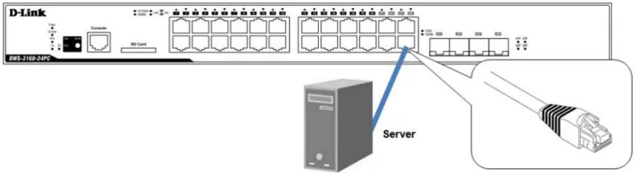
Figure 3-3. Connecting the Switch to a server
Switch to an Access Point directly
This Switch can be used to connect to Wireless Access Points (like the DWL-8600AP, DWL-3600AP, and DWL-6600AP) to manage, configure and monitor them. An Access Point can either be configured as a Standalone or a Managed Access Point. For the Unified System to function at optimal performance and flexibility, it is more feasible to configure the Access Point to function as a Managed Access Point. This means that the Switch will manage the Access Point.
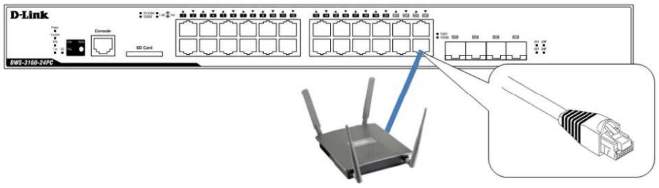
Chapter 4 Switch Management
Management Options
Connecting to the Console Port
Connecting using SNMP
Connecting using the Web User Interface
Management Options
This Switch series provides multiple access platforms that can be used to configure, manage and monitor networking features available on this Switch. Currently there are three management platforms available and they are described below.
The Command Line Interface (CLI) through the Serial Port or remote Telnet
This Switch can be managed, out-of-band, by using the console port on the front panel of the Switch. Alternatively, the Switch can also be managed, in-band, by using a Telnet connection to any of the Copper/SFP ports in this Switch. The command line interface provides complete access to all Switch management features.
SNMP-based Management
The Switch can be managed with an SNMP-compatible console program. The Switch supports SNMP version 1.0, version 2.0 and version 3.0. The SNMP agent decodes the incoming SNMP messages and responds to requests with MIB objects stored in the database. The SNMP agent updates the MIB objects to generate statistics and counters.
Web-based Management Interface
After successfully installing the Switch, the user can configure the Switch, monitor the LED panel, and display statistics graphically using a Web browser, such as Microsoft® Internet Explorer (version 5.5 and later), Mozilla Firefox (version 2.0 and later), Safari (version 4.0 and later), and Google Chrome (version 6.0 and later).
Connecting to the Console Port
The front panel of the Switch provides a port that enables a connection to a computer monitoring and configuring the Switch. The console port is an RJ-45 port and requires a special cable that is included with the Switch, to establish the physical connection.
To use the console port, the following equipment is needed:
- A terminal or a computer with both an RS-232 serial port and the ability to emulate a terminal.
- A console cable with a male DB-9 connector on one end and an RJ-45 connection on the other. This cable should be included with the Switch. It establishes the physical connection to the console port.
Using a terminal to connect to the console port:
Connect the male DB-9 connector on the console cable (shipped with the Switch) to the RS-232 serial port on the computer running terminal emulation software then insert the RJ-45 connector into the RJ-45 console port on the front of the Switch.
Set the terminal emulation software as follows:
- Select the appropriate serial port (COM1 or COM2).
- Set the data rate to 115200 baud.
- Set the data format to 8 data bits, 1 stop bit, and no parity.
- Set flow control to none.
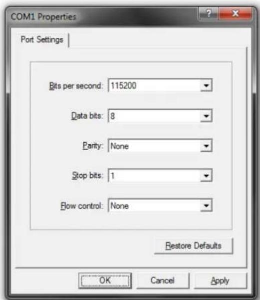
Figure 4- 1. COM1 Properties
- Under Properties, select VT100 for Emulation mode.
- Select Terminal keys for Function, Arrow and Ctrl keys. Make sure to use Terminal keys (not Windows keys) are selected.

NOTE: When using HyperTerminal with the Microsoft® Windows® 2000 operating system, ensure that Windows 2000 Service Pack 2 or later is installed. Windows 2000 Service Pack 2 allows use of arrow keys in HyperTerminal's VT100 emulation. See www.microsoft.com for information on Windows 2000 service packs.
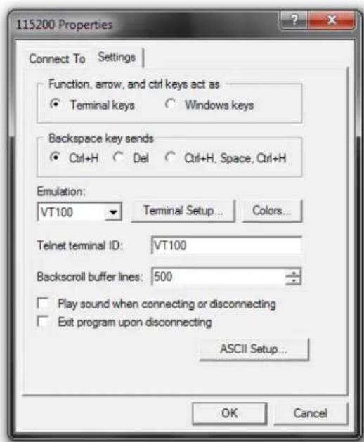
Figure 4-2. Connection Properties
After correctly configuring the terminal, plug the power cable into the power receptacle on the back of the Switch. The boot sequence will appear in the terminal.
Boot Procedure V1.00.001
Power On Self Test 100 %
MAC Address : 00-11-22-33-45-67
H/W Version : A1
Please Wait, Loading V1.00.037 Runtime Image 100 %
UART init 100 %
Starting runtime image
Device Discovery 100 %
Configuration init 100 %
Figure 4-3. Boot up display in console screen
After the boot sequence has been completed, the console login screen will be displayed.
Connecting to the Switch for the first time
The Switch supports user-based security that can allow prevention of unauthorized users from accessing the Switch or changing its settings. This section will explain how to log into the Switch's Command Line Interface via the out-of-band console connection.
Upon initial connection to the Switch, the login screen appears (see example below).
DWS-3160-24PC Gigabit Ethernet Switch
Command Line Interface

Firmware: Build 1.00.037
Copyright(C) 2011 D-Link Corporation. All rights reserved.

UserName:
PassWord:

DWS-3160-24PC:admin#
Figure 4-4. The Switch's Login Screen
By default, there is no Username and Password configured in the account settings of this Switch. This will allow the user to simply connect to this Switch for the first time by pressing the 'Enter' key twice.
After press Enter for both the Username and Password fields, access will be given to enter commands after the command prompt (DWS-3160-24PC:admin#) appears.

NOTE: The first user automatically gets Administrator level privileges. At least one Admin-level user account must be created for the Switch.
Creating a User Account
As you will have noticed by now is that this Switch does not have a default username and password. One of the first and most important tasks will be to create user accounts. Logging in using a predefined administrator-level username will give the user privileged access to the Switch's management software. Also this will prevent unauthorized access to the Switch, and record the passwords for future reference.
An example to create an administrator-level account for the Switch called 'NewUser':
DWS-3160-24PC:admin#create account admin NewUser
Command: create account admin NewUser

Enter a case-sensitive new password:*****
Enter the new password again for confirmation:*****
Success.

DWS-3160-24PC:admin#
Figure 4-5. To create a user account
- At the CLI command prompt, enter the 'create account admin NewUser' command and press 'Enter'. This will create a new administrator-level account called 'NewUser'.
- The Switch will then prompt the user to enter a password. Enter the password for the administrator account and press the 'Enter' key.
- The Switch will again prompt the user to enter the same password again to verify it. Enter the same password and press the 'Enter' key.
- A "Success" response message will be displayed, by the Switch, to verify the successful creation of the new administrator-level account.

NOTE: Passwords are case sensitive. User names and passwords can be up to 15 characters in length.
Configuring the IP Address
Each Switch must be assigned its own IP Address, which is used for communication with an SNMP network manager or other TCP/IP applications. The Switch's default IP address is 10.90.90.90. You can change the Switch's default IP address to fit into your networking address range.
The Switch is also assigned a unique MAC address by the factory. This MAC address cannot be changed, and can be found by entering the command "show switch" into the command line interface, as shown below.
DWS-3160-24PC:admin#show switch
Command: show switch

Device Type : DWS-3160-24PC Gigabit Ethernet Switch
MAC Address : 00-11-22-33-45-67
IP Address : 10.90.90.90 (Manual)
VLAN Name : default
Subnet Mask : 255.0.0.0
Default Gateway : 0.0.0.0
Boot PROM Version : Build 1.00.001
Firmware Version : Build 1.00.037
Hardware Version : A1
System Name :
System Location :
System Uptime : 0 days, 0 hours, 0 minutes, 34 seconds
System Contact :
Spanning Tree : Disabled
GVRP : Disabled
IGMP Snooping : Disabled
MLD Snooping : Disabled
VLAN Trunk : Disabled
Telnet : Enabled (TCP 23)
Web : Enabled (TCP 80)
SNMP : Disabled
SSL Status : Disabled

CTRL+C ESC q Quit SPACE n Next Page ENTER Next Entry a All
Figure 4-6. The 'show switch' command
The IP address of the Switch must be configured before it can be managed, by the user, via the Web User Interface.
An example to change the IP address of the Switch to '10.90.90.90', using a subnet mask of '255.0.0.0':
DWS-3160-24PC:admin#config ipif System ipaddress 10.90.90.91/8
Command: config ipif System ipaddress 10.90.90.91/8
Success.
DWS-3160-24PC:admin#
Figure 4-7. To change the IP address
- At the CLI command prompt, enter the 'config ipif System ipaddress 10.90.90.91/8' command and press 'Enter'. This will change the IP address of the Switch to 10.90.90.91.
- Also notice the subnet mask's notation method. Here we use the value '/8' which means that the subnet mask will be change to 255.0.0.0 using the CIDR notation.
- Alternatively, if you don't know the CIDR notation for your subnet mask, you can also simply type out the subnet mask. For example: 'config ipif System ipaddress 10.90.90.91/255.0.0.0'.
The Switch can now be configured and accessed using Telnet or the Web-based management. The Switch's IP address can also automatically be obtained by using the BOOTP or DHCP protocol.
Connecting using SNMP
The Switch can be managed with an SNMP-compatible console program. The Simple Network Management Protocol (SNMP) operates on the Application Layer of the OSI model and is designed specifically for managing and monitoring network devices. The SNMP agent decodes the incoming SNMP messages and responds to requests with MIB objects stored in the database. The SNMP agent updates the MIB objects to generate statistics and counters.
D-Link provides a professional network management software package, called D-View 6.0 that uses SNMP to connect, configure, manage and monitor this Switch. The D-View ^® 6.0 SNMP Network Management System is a software tool that facilitates the central administration of a network with various SNMP-enabled devices.
Figure 4-8. D-Link's D-View SNMP Software
Managed devices that support SNMP include software (referred to as an agent), which runs locally on the device. A defined set of variables (managed objects) is maintained by the SNMP agent and used to manage the device. These objects are defined in a Management Information Base (MIB), which provides a standard presentation of the information controlled by the on-board SNMP agent. SNMP defines both the format of the MIB specifications and the protocol used to access this information over the network.
This Switch supports SNMP Versions 1, 2c, and 3 alternatively known as SNMPv1, SNMPv2c and SNMPv3. The administrator may specify which version of SNMP to use to monitor and control the Switch. The three versions of SNMP vary in the level of security provided between the management station and the network device.
In SNMPv1 and SNMPv2c, user authentication is accomplished using 'community strings', which function like passwords. The remote user SNMP application and the Switch's SNMP must use the same community string. SNMP packets from any station that has not been authenticated are ignored (dropped).
The default community strings for the Switch used for SNMPv1 and SNMPv2c are:
• public - Allows authorized management stations to retrieve MIB objects.
- private - Allows authorized management stations to retrieve and modify MIB objects.
DWS-3160-24PC:admin# show snmp community
Command: show snmp community

SNMP Community Table
Community Name View Name Access Right

private CommunityView read_write
public CommunityView read_only

Total Entries: 2

DWS-3160-24PC:admin#
Figure 4-9. To view the SNMP community strings
SNMPv3 uses a more sophisticated authentication process that is separated into two parts.
- The first part is to maintain a list of users and their attributes that are allowed to act as SNMP managers.
- The second part describes what each user on that list can do as an SNMP manager.
The Switch allows groups of users to be created and configured with a shared set of privileges. The SNMP version may also be configured for a specific group of SNMP managers. A group of SNMP managers can be created to view read-only information or to receive traps using SNMPv1 while assigning a higher level of security to another group, granting read/write privileges using SNMPv3.
Using SNMPv3, individual users or groups of SNMP managers can be allowed to perform or be restricted from performing specific SNMP management functions. The functions allowed or restricted are defined using the Object Identifier (OID) associated with a specific MIB. An additional layer of security is available for SNMPv3 in which SNMP messages may be encrypted.
Traps
Traps are messages that alert network personnel of events that occur on the Switch. The events can be as serious as a reboot (someone accidentally turned OFF the Switch), or less serious like a port status change. The Switch generates traps and sends them to the trap recipient (or network manager). Typical traps include trap messages for Authentication Failure, Topology Change and Broadcast/Multicast Storm.
Management Information Base (MIB)
The Management Information Base (MIB) stores management and counter information. The Switch uses the standard MIB-II Management Information Base module. Consequently, values for MIB objects can be retrieved from any SNMP-based network management software. In addition to the standard MIB-II, the Switch also supports its own proprietary enterprise MIB as an extended Management Information Base. The proprietary MIB may also be retrieved by specifying the MIB Object Identifier. MIB values can be either read-only or read-write.
Connecting using the Web User Interface
All software functions of the Switch can be managed, configured, and monitored via the embedded Web-based (HTML) interface. This can be done from any remote station on the network through a standard web browser, such as Internet Explorer (version 5.5 and later), Mozilla Firefox (version 2.0 and later), Safari (version 4.0 and later), or Google Chrome (version 6.0 and later). The browser acts as a universal access tool and can communicate directly with the Switch using the HTTP protocol.
All the software features that can be configured using the Command Line Interface can also be configured using the Web User Interface. The Web User Interface is thus an alternative configuration method for the lesser analytical users.
Logging onto the Web Manager
To access the Web User Interface the user simply runs the standard web browser and enter the Switch's IP address into the address bar of the browser and press the 'Enter' key.

Figure 4-10. Displays entering the IP address in Internet Explorer

NOTE: The factory default IP address is 10.90.90.90.
This will open the user authentication window, as seen below.
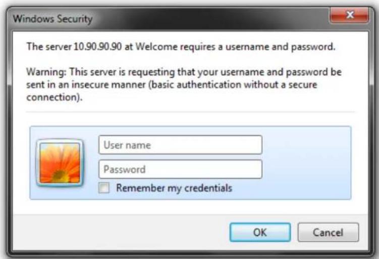
Figure 4-11. Enter Network Password window
As there is no default User name or Password, click OK to proceed. This will open the Web-based User Interface. The Switch management features available in the Web-based manager are explained below.
Areas of the User Interface
After a successful connection to the Web User Interface has been made, the following page should be displayed.
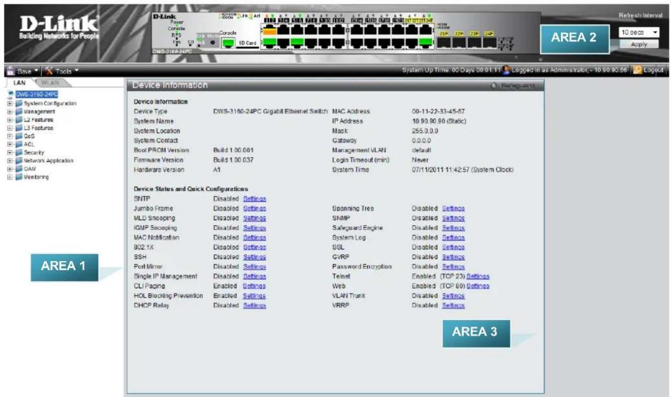
Figure 4-12. Main Web Manager window
On this page we will find three main areas to observe.
| Area Number Function | |
| AREA 1 | This area is divided up into two main sections. The LAN section can be used to configure anything that is related to the Ethernet network segments. The WLAN section can be used to configure anything that is related to the Wireless LAN segments. Both sections have Folder links that can be expanded and both sections have Window links that will navigate the user to a specific feature's configuration page. This can be done by simply click on them with the mouse pointer. |
| AREA 2 | This area displays a graphical, real-time image of the front panel of the Switch. When clicking on active ports, in this image, the user will be navigated to the port activity page for the specific port. Also in this area, on the bottom left, the user can access the Save and Tools pages by simply clicking on them. On the top right, the user can also select the Refresh Interval time for this area. Click Apply to accept the change made. |
| AREA 3 | This area is where the magic really happens. After clicking on a Window link, in Area 1, this area will display the configuration page for the specific features that can be configured or monitored. |
Chapter 5 D-Link Unified Access System
D-Link Unified Access System Components D-Link Unified Access System Topology
The D-Link Unified Access System is a wireless local area network (WLAN) solution that enables WLAN deployment while providing state-of-the-art wireless networking features. It is a scalable solution that provides secure wireless connectivity and seamless layer 2 and layer 3 roaming for end users.
D-Link Unified Access System Components
The D-Link Unified Access System components include the D-Link Unified Switch and the D-Link Access Point (AP).
With the default D-Link License Management Service (DLMS) agreement, this Switch can manage up to 12 unified Access Points. After an optional upgrade of the license agreement, purchased from D-Link, this Switch can manage up to 48 unified Access Points per unified Switch. The most powerful feature of this Switch is that up to 4 Switches can form a cluster to manage up to 192 unified Access Points centrally with a single IP address.
The switch tracks the status and statistics for all associated WLAN traffic and devices. You can configure up to 4 peer D-Link Unified Switches that share various information about APs and their associated wireless clients. The peer Unified Switches can be directly connected to each other, separated by Layer 2 bridges, or located in different IP Subnets. Wireless clients can roam among the access points managed by peer Unified Switches without losing network connections. Whether or not you have a peer group, the D-Link Unified Access System can support a total of 8000 wireless clients
D-Link Unified Switch
The D-Link Unified Switch handles Layer 2+ switching functions for traffic on the wired and wireless LAN. The Unified Switch user interface allows you to configure and monitor all AP settings and maintain a consistent configuration among all APs in the network.
The Unified Switch supports advanced data path connectivity, mobility control, security safeguards, control over radio and power parameters, and management features for both network and element control. The Unified Switch allows you to control the discovery, validation, authentication, and monitoring of peer Unified Switches, D-Link Access Points, and clients on the WLAN, including discovery and status of rogue APs and clients.
The D-Link Unified Access System works with the following D-Link switches:
• DWS-3160-24TC
• DWS-3160-24PC
D-Link Access Point
The D-Link Access Point can operate in one of two modes: Standalone Mode or Managed Mode.
- In Standalone Mode, the D-Link Access Point acts as an individual access point in the network, and you manage it by connecting to the AP and using the Administrator Web User Interface (UI) or Command Line Interface (CLI).
- In Managed Mode, the D-Link Access Point is part of the D-Link Unified Access System, and you manage it by using the D-Link Unified Switch. If an AP is in Managed Mode, the Administrator Web UI services on the AP are disabled. Access is limited to the CLI through Telnet.
The Standalone Mode is appropriate for small networks with only a few APs. The Managed Mode is useful for any size network. If you start out with D-Link Access Points in Standalone Mode, you can easily transition the APs to Managed Mode when you add a Unified Switch to the network. By using the AP in Managed Mode, you can centralize AP
management and streamline the AP upgrade process by pushing configuration profiles and software upgrades from the Unified Switch to the managed APs. The Web UI Reference Guide and the CLI Reference Guide primarily describes the D-Link Access Point in Managed Mode.
The D-Link Unified Access System works with the following D-Link access points:
- DWL-3600AP
- DWL-8600AP
- DWL-6600AP
Each access point supports up to eight virtual access points (VAPs) on each radio. The VAP feature allows you to segment each physical access point into eight logical access points (per radio) that each supports a unique SSID, VLAN ID, and security policy.
WLAN Visualization
The D-Link Unified Access System includes the WLAN Visualization tool, which provides a graphical representation of your wireless network through a Web browser. WLAN Visualization detects and displays the D-Link Unified Switch, D-Link Access Points, other access points, and all wireless clients associated with the D-Link Access Point. You can import information about your building layout to customize the network view.
The figure below shows an example of a floor plan and network with a D-Link Unified Switch that manages two APs. The graph also shows a peer switch and a rogue AP in the network.
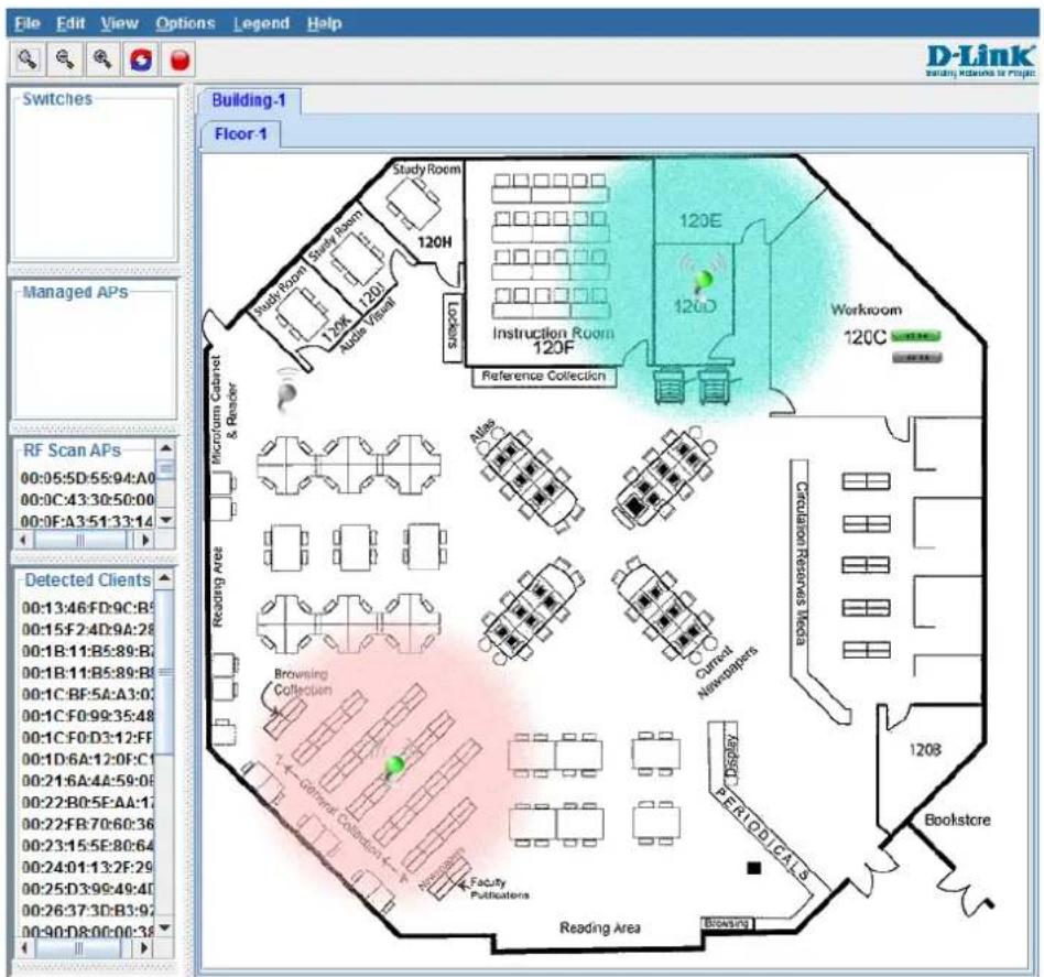
Figure 5-1 WLAN Visualization
The WLAN Visualization tool provides an AP power display with color-coded channels to help you determine where to physically place access points to reduce interference or increase coverage on your WLAN.
D-Link Unified Access System Topology
The WLAN network topology you use depends on the size and requirements of your network. Small-to-medium networks might require only one Unified Switch that manages a few D-Link Access Points. For larger networks that need greater roaming capabilities for wireless clients, a deployment with multiple peer switches that each manages several APs might be appropriate.
Single Unified Switch Deployment
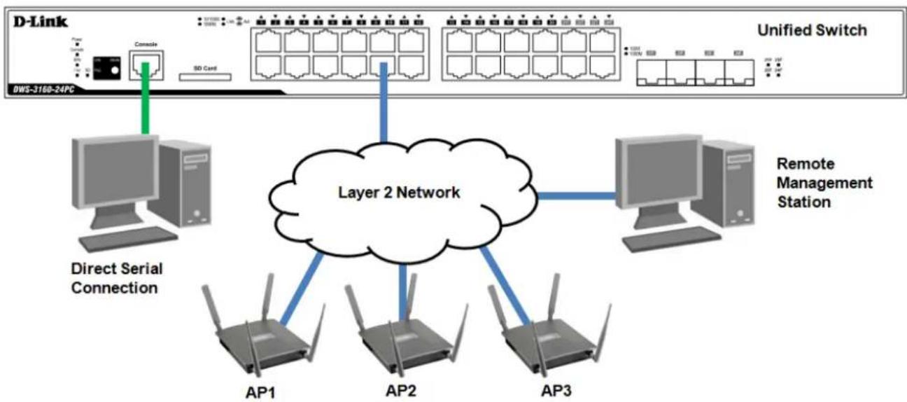
When you deploy a D-Link Access Point, the D-Link Unified Switch can automatically detect the AP and assign a default profile, which includes automatic RF channel selection and automatic power adjustment.
flowchart
graph TD
    A["D-Link"] --> B["Console"]
    B --> C["SD Card"]
    C --> D["Unified Switch"]
    D --> E["AP1"]
    D --> F["AP2"]
    D --> G["AP3"]
    E --> H["Layer 2 Network"]
    F --> H
    G --> H
    H --> I["AP1"]
    H --> J["AP2"]
    H --> K["AP3"]
    I --> L["AP1"]
    J --> M["AP2"]
    K --> N["AP3"]
    L --> O["AP1"]
    M --> P["AP2"]
    N --> Q["AP3"]
    O --> R["AP1"]
    P --> S["AP2"]
    Q --> T["AP3"]
    R --> U["AP1"]
    S --> V["AP2"]
    T --> W["AP3"]
    U --> X["AP1"]
    V --> Y["AP2"]
    W --> Z["AP3"]
    X --> AA["AP1"]
    Y --> AB["AP2"]
    Z --> AC["AP3"]
    AA --> AD["AP1"]
    AB --> AE["AP2"]
    AC --> AF["AP3"]
    AD --> AG["AP1"]
    AE --> AH["AP2"]
    AF --> AI["AP3"]
Figure 5-2 One Unified Switch with Three APs
When the APs are on the same subnet and have the same SSID, wireless clients can seamlessly roam among the three APs with no interruption in network access. The client keeps the same IP address and does not need to re-authenticate when it moves into the broadcast area of a different AP. Configuration changes to the APs are managed by the switch simultaneously or on a per-AP basis.
Peer Unified Switch Deployment
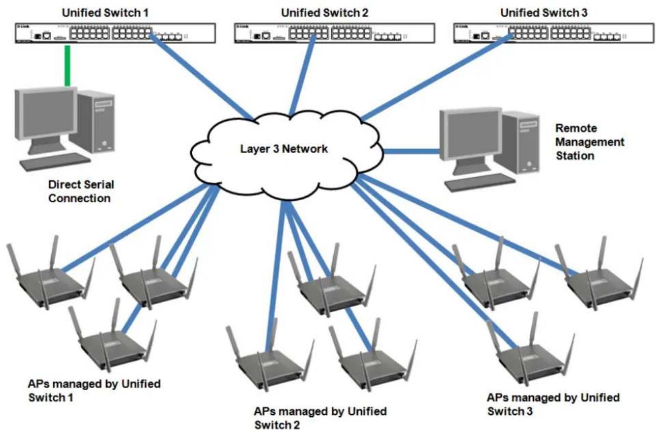
To support larger networks, you can configure up to four switches as peers, which increases the size and range of the WLAN. The Unified Switch and the APs it manages do not need to be on the same subnet.
flowchart
graph TD
    A["Unified Switch 1"] --> B["Layer 3 Network"]
    C["Unified Switch 2"] --> B
    D["Unified Switch 3"] --> B
    E["Direct Serial Connection"] --> B
    F["APs managed by Unified Switch 1"] --> B
    G["APs managed by Unified Switch 2"] --> B
    H["APs managed by Unified Switch 3"] --> B
    I["Remote Management Station"] --> B
    B --> J["APs managed by Unified Switch 1"]
    B --> K["APs managed by Unified Switch 2"]
    B --> L["APs managed by Unified Switch 3"]
Figure 5-3 Unified Access System Deployment with 3 Unified Switches
Peer Unified Switches share information about APs and allow Layer 3 roaming among them. To support this, peer Unified Switches establish IPv4 tunnels so that the wireless client keeps the same IP address even when the client associates with an access point in a different subnet. The Layer 3 roaming service allows wireless phone users to roam between access points connected to different subnets without dropping calls.
Chapter 6 Appendix Section
Appendix A – Technical Specifications
General
| Feature Detailed Description | |
| Standards | IEEE 802.3 10BASE-T EthernetIEEE 802.3u 100BASE-TX Fast EthernetIEEE 802.3ab 1000BASE-T Gigabit EthernetIEEE 802.3z 1000BASE-T (SFP “Mini GBIC”)IEEE 802.1D/2004/Spanning Tree (802.1s, 802.1w)IEEE 802.1Q-2005 VLANIEEE 802.1p Priority QueuesIEEE 802.1X Network Access ControlIEEE 802.3 Nway Auto-negotiationIEEE 802.3ad Link Aggregation ControlIEEE 802.3x Full-duplex Flow ControlIEEE 802.1u Fast Ethernet |
| Protocols | CSMA/CD |
| Data Transfer Rates:EthernetFast EthernetGigabit Ethernet | Half-duplex Full-duplex10 Mbps 20Mbps100Mbps 200Mbps---- 2000Mbps |
| Network Cables | Cat.5 Enhanced for 1000BASE-TUTP Cat.5, Cat. 5 Enhanced for 100BASE-TXUTP Cat.3, 4, 5 for 10BASE-TEIA/TIA-568 100-ohm screened twisted-pair (STP)(100m) |
Physical and Environmental
| Feature Detailed Description | |
| Internal Power Supply | DWS-3160-24TC: 100-240VAC, 50-60Hz, 60 WattDWS-3160-24PC: 100-240VAC, 50-60Hz, 589 Watt |
| Optional Redundant Power Supply | One connector in rear panel to install an optional external RPS. When internal power fails, the optional external RPS will automatically take over all the power supply immediately.DWS-3160-24TC: DPS-200DWS-3160-24PC: DPS-700 |
| Fans | DWS-3160-24TC: 2 FansDWS-3160-24PC: 4 Fans |
| Power Consumption | DWS-3160-24TC: 37.7 Watts (Max.)DWS-3160-24PC: 467.3 Watts (Max.) |
| Operating Temperature | 0~50°C |
| Storage Temperature | -40~70°C |
| Humidity | Operation: 10%-90% RH non-condensingStorage: 5% ~ 90% RH non-condensing |
| Dimensions | DWS-3160-24TC: 440mm (W) x 210mm (D) x 44mm (H)DWS-3160-24PC: 440mm (W) x 310mm (D) x 44mm (H) |
| Weight | DWS-3160-24TC: 2.552kg.DWS-3160-24PC: 5.242kg. |
| SD Card | At least 4G supported. |
| Power-over-Ethernet | IEEE 802.3af and 802.3at compliance.Provides up to 15.4 Watts for 802.3af compliant devices.Provides up to 30 Watts for 802.3at compliant devices.System PoE power budget: 740W.Auto-discover the connection of PD and immediately providing power.Auto-disable port if the port current is over 350mA.Feeding power over pins 1, 2, 3 & 6 of 8 wires of UTP cables.Supports dynamic PoE power allocation.Support per-port PoE priority setting, default setting all ports low priority. |
| EMI | CE Class A, FCC Class A, VCCI Class A, C-Tick Report |
| Safety | UL, CB Report, CSA International Mark |
Performance
| Feature Detailed Description | |
| Transmission Method | Store-and-forward |
| Packet Buffer | 2 Mbyte (Max) |
| Maximum Forwarding Rate | DWS-3160-24TC: 35.72 million packets per second.DWS-3160-24PC: 35.72 million packets per second. |
| Switching Capability | DWS-3160-24TC: 48GbpsDWS-3160-24PC: 48Gbps |
| Priority Queues | 8 Priority Queues per port |
| MAC Address Table | Supports 16K MAC addresses |
| Wire Speed | Full-wire speed (full-duplex) operation on all ports including Gigabit ports. |
| Virtual Stacking / Clustering | Support D-Link Single IP Management v1.6Able to manage up to 4 Unified Switches in a virtual stack with a single IP address.Manage up to 32 devices in a virtual stack with a single IP address. |
LED Indicators
| Location | LED Indicative | Color | Status | Description |
| Per Device Power | Green | Solid Light | Power On | |
| Light off Power Off | ||||
| Console | Green | Solid Light | Console on | |
| Light off Console off | ||||
| RPS | Green | Blinking | When switch detects that RPS is connected | |
| Solid Light RPS in using | ||||
| Light off RPS off | ||||
| Fan Err | Red | Blinking | When any of the fans has failed | |
| Light off When all fans work normally | ||||
| Port LED Mode Indicator | Green | Solid Light | A LED Mode Select Button to switch Link/Act/Speed Mode | |
| Solid Light A LED Mode Select Button to switch PoE Mode | ||||
| LED Per 10/100/1000 Mbps Port | Link/Act/Speed Mode | Green | Solid Light | When there is a secure connection (or link) to 1000Mbps Ethernet device at any of the ports. |
| Blinking When there is reception or transmission of data occurring at 1000Mbps. | ||||
| Orange | Solid Light | When there is a secure connection (or link) to 10/100Mbps Ethernet device at any of the ports. | ||
| Blinking When there is reception or transmission of data occurring at 10/100Mbps. | ||||
| Off | Light off | No link. | ||
| PoE Mode (DWS-3160-24PC) | Green | Solid Light | Power feeding. | |
| Orange | Solid Light | Error Condition. | ||
| Off | Light Off | No Power feeding. | ||
| LED Per SFP Port | Link/Act | Green | Solid Light | When there is a secure connection (or link) to 1000Mbps Ethernet device at any of the ports. |
| Blinking When there is reception or transmission of data occurring at 1000Mbps. | ||||
| Orange | Solid Light | When there is a secure connection (or link) to 100Mbps Ethernet device at any of the ports. | ||
| Blinking When there is reception or transmission of data occurring at 100Mbps. | ||||
| Off | Light off | No link | ||
| SD | Green | Solid Light | SD card plug-in | |
| Blinking Read/Write | ||||
| Light off No link | ||||
| Red | Solid Light | SD card failure | ||
Port Functions
| Feature Detailed Description | |
| Console Port | RJ-45 interface for out-of-band CLI configuration |
| Copper Ports(10/100/1000Mbps) | Compliant to following standards:IEEE 802.3 complianceIEEE 802.3u complianceIEEE 802.3ab complianceSupport Half/Full-Duplex operationsAuto-negotiation, Auto MDI/MDIXIEEE 802.3x Flow Control support for Full-Duplex mode, Back Pressure when Half-Duplex mode, and Head-of-line blocking prevention |
| SFP Ports(1000Mbps) | Compliant to following standards:IEEE 802.3z complianceIEEE 802.3x Flow Control support for Full-Duplex mode.Support Auto-negotiation for Full-Duplex/ flow control operationsSFP Transceivers Supported:DEM-310GT (1000BASE-LX, Single-mode, 10km)DEM-311GT (1000BASE-SX, Multi-mode, 500m)DEM-312GT2 (1000BASE-SX, Multi-mode, 2km)DEM-314GT (1000BASE-LHX, Single-mode, 50km)DEM-315GT (1000BASE-ZX, Single-mode, 80km)DEM-330T/R (WDM transceiver, Single-Mode 10km)DEM-331T/R (WDM transceiver, Single-Mode 40km)DGS-712 (1000BASE-T,Copper, 100m)DEM-210 (100BASE-FX, Single-Mode 15km)DEM-211 (100BASE-FX, Multi-mode, 2km)DEM-220T/R (100BASE-BX, Single-Mode, 20km) |
Wireless Functions
| Feature Detailed Description | |
| Max. AP per Switch | Default DLMS: 12 Unified Access Points.Upgraded DLMS: 48 Unified Access Points. |
| Max. Users per Switch | Up to 1024 Tunneled usersUp to 2048 non-Tunneled users |
| Multiple SSIDs per AP | Up to 16 SSIDs per radio, 32 SSIDs per AP |
| Multiple SSIDs per Switch | Up to 64 SSIDs can be configured and stored on the Switch. |
| Visualized AP Management Tool | Support up to 16 JPEG files. |
| Unified AP Support | DWL-8600AP, DWL-3600AP, DWL-6600AP |
| Wireless Standards | IEEE 802.11a, 802.11b, 802.11g, 802.11d, 802.11h, 802.11n |
| Security Modes | NoneWEP - Open SystemWEP – Shared KeyWEP – 802.1x (Dynamic WEP)WPA/WPA2 – Shared Key (Personal)WPA/WPA2 – 802.1x (Enterprise) |
| 802.1X EAP Types | EAP-MD5, EAP-TLS, EAP-TTLS, EAP-FAST, EAP-SIM, PEAP-GTC, PEAP-TLS, PEAP-MS-CHAPv2 |
| Captive Portal | Support Radius and Local User Databases.Up to 128 users in the Local Database.Up to 1024 concurrent on-line users.Support up to 6 customized web pages. |
Appendix B - Cables and Connectors
Ethernet Cable
When connecting the Switch to another switch, a bridge or hub, a normal cable is necessary. Please review these products for matching cable pin assignment.
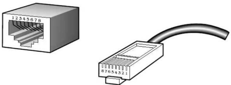
The following diagrams and tables show the standard RJ-45 receptacle/connector and their pin assignments.
natural_image
Illustration of two Ethernet ports: one shown with a 12345678 port, the other with an attached 87654321 network cable (no text or symbols on the devices themselves)Figure B- 1. The standard RJ-45 port and connector
| RJ-45 Pin Assignments | ||
| Contact | MDI-X Port | MDI-II Port |
| 1 | RD+ (receive) TD+ (transmit) | |
| 2 | RD- (receive) | TD- (transmit) |
| 3 | TD+ (transmit) RD+ (receive) | |
| 4 | 1000BASE-T 1000BASE-T | |
| 5 | 1000BASE-T 1000BASE-T | |
| 6 | TD- (transmit) | RD- (receive) |
| 7 | 1000BASE-T 1000BASE-T | |
| 8 | 1000BASE-T 1000BASE-T | |
Console Cable
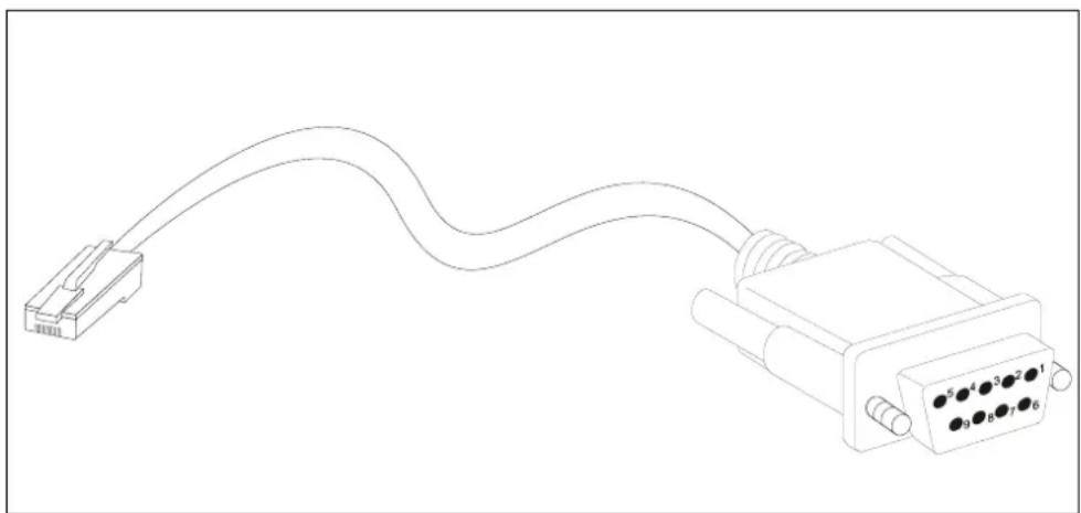
When connecting the Switch a PC, a Console cable is necessary. The following diagrams and tables show the standard Console-to-DJ-45 receptacle/connector and their pin assignments.
natural_image
Line drawing of a USB connector with terminal pins (no text or symbols)Figure B-2. Console-to-RJ-45 Cable
| Console-RJ-45 Pin Assignments | ||
| Pin | Console (DB9/RS232) | RJ-45 |
| 1 | Not Used Not Used | |
| 2 | RXD Not Used | |
| 3 | TXD TXD | |
| 4 | Not Used GND | |
| 5 | GND (shared) GND | |
| 6 | Not Used RXD | |
| 7 | Not Used Not Used | |
| 8 | Not Used Not Used | |
Redundant Power Supply (RPS) Cable
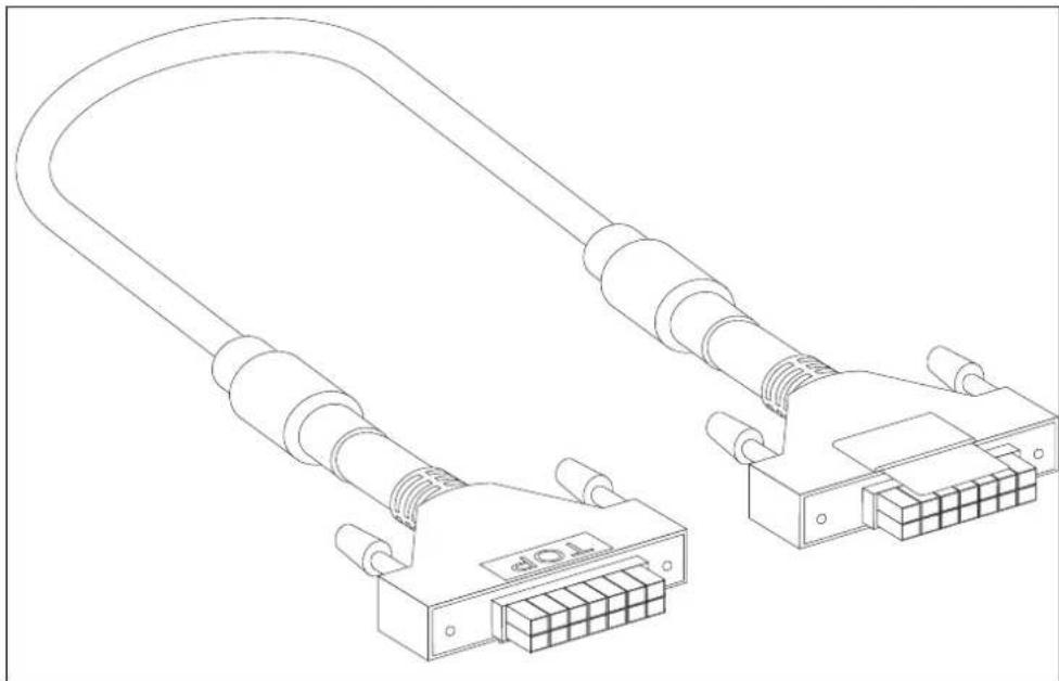
When connecting the Switch to a Redundant Power Supply, an RPS cable is necessary. Please review these products for matching cable pin assignment. The following diagrams and tables show the standard RPS receptacle/connector and their pin assignments.
14-pin DC power cable
natural_image
Line drawing of two connected I/O connectors with 24-pin connector (no text or symbols)Figure B- 3. Redundant Power Supply (RPS) 14-pin DC Power Cable
| RPS 14-pin DC Power Cable Pin Assignments | ||
| Pin | Device | DPS-200 |
| 1 | GND GND | |
| 2 | NC NC | |
| 3 | +12V +12V | |
| 4 | +12V +12V | |
| 5 | +12V +12V | |
| 6 | +12V +12V | |
| 7 | GND GND | |
| 8 | GND GND | |
| 9 | NC Power Good | |
| 10 | NC Power Present | |
| 11 | Power Good NC | |
| 12 | Power Present NC | |
| 13 | GND GND | |
| 14 | GND GND | |
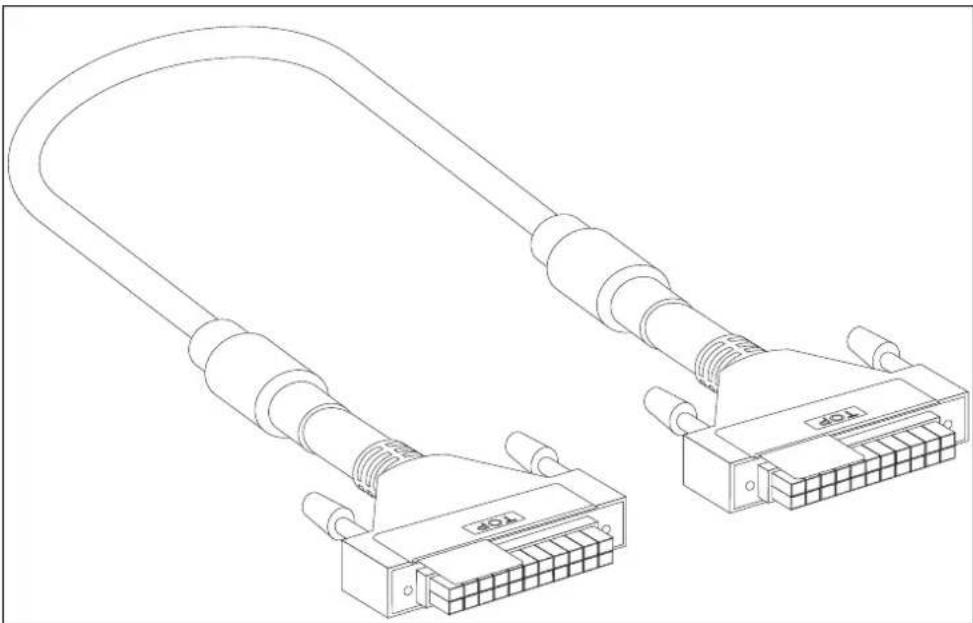
22-pin DC power cable
natural_image
Line drawing of two connected I/O ports with coaxial connectors (no text or symbols)Figure B- 4. Redundant Power Supply (RPS) 22-pin DC Power Cable
| RPS 22-pin DC Power Cable Pin Assignments | ||
| Pin | Device | DPS-700 |
| 1 | -54Vrtn -54Vrtn | |
| 2 | -54V -54V | |
| 3 | +12V +12V | |
| 4 | +12V +12V | |
| 5 | +12V +12V | |
| 6 | +12V +12V | |
| 7 | NC/GND GND | |
| 8 | +12Ven +12Ven | |
| 9 | LS-54V | LS-54V |
| 10 | -54V -54V | |
| 11 | -54Vrtn -54Vrtn | |
| 12 | GND NC/GND | |
| 13 | GND GND | |
| 14 | RPS Present Status_2 | |
| 15 | Status_1 RPS PG | |
| 16 | Status_2 RPS Present | |
| 17 | RPS PG Status_1 | |
| 18 | GND GND | |
| 19 | +12VRTNsen +12VRTNsen | |
| 20 | LS+12V LS+12V | |
| 21 | -54Vsen | -54Vsen |
| 22 | -54VRTNsen | -54VRTNsen |
Appendix C – Module Specifications and Cable Lengths
Use the following table to as a guide for the module specs and maximum cable lengths.
| Standard | Media Type | Maximum Distance |
| Mini-GBIC | 1000BASE-LX, Single-mode fiber module | 10km |
| 1000BASE-SX, Multi-mode fiber module | 550m / 2km | |
| 1000BASE-LH, Single-mode fiber module | 50km | |
| 1000BASE-ZX, Single-mode fiber module | 80km | |
| 1000BASE-T | Category 5e UTP Cable 100m | |
| 100BASE-TX | Category 5 UTP Cable (100 Mbps) | 100m |
| 10BASE-T | Category 3, 4 or 5 UTP Cable (10 Mbps) | 100m |
| DEM-310GT | 1000BASE-LX, Single-mode | 10km |
| DEM-311GT | 1000BASE-SX, Multi-mode | 500m |
| DEM-312GT2 | 1000BASE-SX, Multi-mode | 2km |
| DEM-314GT | 1000BASE-LH, Single-mode | 50km |
| DEM-315GT | 1000BASE-ZX, Single-mode | 80km |
| DEM-210 | 100BASE-FX, Single-mode | 15km |
| DEM-330T | TX-1550/RX-1310 nm, Single-mode | Up to 10km |
| DEM-330R | TX-1310/RX-1550 nm, Single-mode | Up to 10km |
| DEM-331T | TX-1550/RX-1310 nm, Single-Mode | Up to 40km |
| DEM-331R | TX-1310/RX-1550 nm, Single-Mode | Up to 40km |
| DGS-712 | 1000BASE-T, Copper | 100m |
Network pluggable optical modules meet the following regulatory requirements:
• Class 1 Laser Product
• EN60825-1+A2:2001 or later, European laser standard
• FCC 21 CFR Chapter 1, Subchapter J in accordance with FDA & CDRH requirements
Subject to the terms and conditions set forth herein, D-Link Systems, Inc. ("D-Link") provides this Limited Warranty:
• Only to the person or entity that originally purchased the product from D-Link or its authorized reseller or distributor, and
- Only for products purchased and delivered within the fifty states of the United States, the District of Columbia, U.S. Possessions or Protectorates, U.S. Military Installations, or addresses with an APO or FPO.
Limited Warranty: D-Link warrants that the hardware portion of the D-Link product described below ("Hardware") will be free from material defects in workmanship and materials under normal use from the date of original retail purchase of the product, for the period set forth below ("Warranty Period"), except as otherwise stated herein.
Limited Lifetime Warranty for the product is defined as follows:
- Hardware: For as long as the original customer/end user owns the product, or five (5) years after product discontinuance, whichever occurs first (excluding power supplies and fans)
• Power supplies and fans: Three (3) Year
- Spare parts and spare kits: Ninety (90) days
The customer's sole and exclusive remedy and the entire liability of D-Link and its suppliers under this Limited Warranty will be, at D-Link's option, to repair or replace the defective Hardware during the Warranty Period at no charge to the original owner or to refund the actual purchase price paid. Any repair or replacement will be rendered by D-Link at an Authorized D-Link Service Office. The replacement hardware need not be new or have an identical make, model or part. D-Link may, at its option, replace the defective Hardware or any part thereof with any reconditioned product that D-Link reasonably determines is substantially equivalent (or superior) in all material respects to the defective Hardware. Repaired or replacement hardware will be warranted for the remainder of the original Warranty Period or ninety (90) days, whichever is longer, and is subject to the same limitations and exclusions. If a material defect is incapable of correction, or if D-Link determines that it is not practical to repair or replace the defective Hardware, the actual price paid by the original purchaser for the defective Hardware will be refunded by D-Link upon return to D-Link of the defective Hardware. All Hardware or part thereof that is replaced by D-Link, or for which the purchase price is refunded, shall become the property of D-Link upon replacement or refund.
Limited Software Warranty: D-Link warrants that the software portion of the product ("Software") will substantially conform to D-Link's then current functional specifications for the Software, as set forth in the applicable documentation, from the date of original retail purchase of the Software for a period of ninety (90) days ("Software Warranty Period"), provided that the Software is properly installed on approved hardware and operated as contemplated in its documentation. D-Link further warrants that, during the Software Warranty Period, the magnetic media on which D-Link delivers the Software will be free of physical defects. The customer's sole and exclusive remedy and the entire liability of D-Link and its suppliers under this Limited Warranty will be, at D-Link's option, to replace the non-conforming Software (or defective media) with software that substantially conforms to D-Link's functional specifications for the Software or to refund the portion of the actual purchase price paid that is attributable to the Software. Except as otherwise agreed by D-Link in writing, the replacement Software is provided only to the original licensee, and is subject to the terms and conditions of the license granted by D-Link for the Software. Replacement Software will be warranted for the remainder of the original Warranty Period and is subject to the same limitations and exclusions. If a material non-conformance is incapable of correction, or if D-Link determines in its sole discretion that it is not practical to replace the non-conforming Software, the price paid by the original licensee for the non-conforming Software will be refunded by D-Link; provided that the non-conforming Software (and all copies thereof) is first returned to D-Link. The license granted respecting any Software for which a refund is given automatically terminates.
Non-Applicability of Warranty: The Limited Warranty provided hereunder for Hardware and Software portions of D-Link's products will not be applied to and does not cover any refurbished product and any product purchased through the inventory clearance or liquidation sale or other sales in which D-Link, the sellers, or the liquidators expressly disclaim their warranty obligation pertaining to the product and in that case, the product is being sold "As-Is" without any warranty whatsoever including, without limitation, the Limited Warranty as described herein, notwithstanding anything stated herein to the contrary.
Submitting A Claim: The customer shall return the product to the original purchase point based on its return policy. In case the return policy period has expired and the product is within warranty, the customer shall submit a claim to D-Link as outlined below:
- The customer must submit with the product as part of the claim a written description of the Hardware defect or Software nonconformance in sufficient detail to allow D-Link to confirm the same, along with proof of purchase of the product (such as a copy of the dated purchase invoice for the product) if the product is not registered.
- The customer must obtain a Case ID Number from D-Link Technical Support at 1-877-453-5465, who will attempt to assist the customer in resolving any suspected defects with the product. If the product is considered defective, the customer must obtain a Return Material Authorization ("RMA") number by completing the RMA form and entering the assigned Case ID Number at https://rma.dlink.com/.
- After an RMA number is issued, the defective product must be packaged securely in the original or other suitable shipping package to ensure that it will not be damaged in transit, and the RMA number must be prominently marked on the outside of the package. Do not include any manuals or accessories in the shipping package. D-Link will only replace the defective portion of the product and will not ship back any accessories.
- The customer is responsible for all in-bound shipping charges to D-Link. No Cash on Delivery ("COD") is allowed. Products sent COD will either be rejected by D-Link or become the property of D-Link. Products shall be fully insured by the customer and shipped to D-Link Systems, Inc., 17595 Mt. Herrmann, Fountain Valley, CA 92708. D-Link will not be held responsible for any packages that are lost in transit to D-Link. The repaired or replaced packages will be shipped to the customer via UPS Ground or any common carrier selected by D-Link. Return shipping charges shall be prepaid by D-Link if you use an address in the United States, otherwise we will ship the product to you freight collect. Expedited shipping is available upon request and provided shipping charges are prepaid by the customer.
D-Link may reject or return any product that is not packaged and shipped in strict compliance with the foregoing requirements, or for which an RMA number is not visible from the outside of the package. The product owner agrees to pay D-Link's reasonable handling and return shipping charges for any product that is not packaged and shipped in accordance with the foregoing requirements, or that is determined by D-Link not to be defective or non-conforming.
What Is Not Covered: The Limited Warranty provided herein by D-Link does not cover: Products that, in D-Link's judgment, have been subjected to abuse, accident, alteration, modification, tampering, negligence, misuse, faulty installation, lack of reasonable care, repair or service in any way that is not contemplated in the documentation for the product, or if the model or serial number has been altered, tampered with, defaced or removed; Initial installation, installation and removal of the product for repair, and shipping costs; Operational adjustments covered in the operating manual for the product and normal maintenance; Damage that occurs in shipment, due to act of God, failures due to power surge, and cosmetic damage; Any hardware, software, firmware or other products or services provided by anyone other than D-Link; and Products that have been purchased from inventory clearance or liquidation sales or other sales in which D-Link, the sellers, or the liquidators expressly disclaim their warranty obligation pertaining to the product. While necessary maintenance or repairs on your Product can be performed by any company, we recommend that you use only an Authorized D-Link Service Office. Improper or incorrectly performed maintenance or repair voids this Limited Warranty.
Disclaimer of Other Warranties: EXCEPT FOR THE LIMITED WARRANTY SPECIFIED HEREIN, THE PRODUCT IS PROVIDED "AS-IS" WITHOUT ANY WARRANTY OF ANY KIND WHATSOEVER INCLUDING, WITHOUT LIMITATION, ANY WARRANTY OF MERCHANTABILITY, FITNESS FOR A PARTICULAR PURPOSE AND NON-INFRINGEMENT. IF ANY IMPLIED WARRANTY CANNOT BE DISCLAIMED IN ANY TERRITORY WHERE A PRODUCT IS SOLD, THE DURATION OF SUCH IMPLIED WARRANTY SHALL BE LIMITED TO NINETY (90) DAYS. EXCEPT AS EXPRESSLY COVERED UNDER THE LIMITED WARRANTY PROVIDED HEREIN, THE ENTIRE RISK AS TO THE QUALITY, SELECTION AND PERFORMANCE OF THE PRODUCT IS WITH THE PURCHASER OF THE PRODUCT.
Limitation of Liability: TO THE MAXIMUM EXTENT PERMITTED BY LAW, D-LINK IS NOT LIABLE UNDER ANY CONTRACT, NEGLIGENCE, STRICT LIABILITY OR OTHER LEGAL OR EQUITABLE THEORY FOR ANY LOSS OF USE OF THE PRODUCT, INCONVENIENCE OR DAMAGES OF ANY CHARACTER, WHETHER DIRECT, SPECIAL, INCIDENTAL OR CONSEQUENTIAL (INCLUDING, BUT NOT LIMITED TO, DAMAGES FOR LOSS OF GOODWILL, LOSS OF REVENUE OR PROFIT, WORK STOPPAGE, COMPUTER FAILURE OR MALFUNCTION, FAILURE OF OTHER EQUIPMENT OR COMPUTER PROGRAMS TO WHICH D-LINK'S PRODUCT IS CONNECTED WITH, LOSS OF INFORMATION OR DATA CONTAINED IN, STORED ON, OR INTEGRATED WITH ANY PRODUCT RETURNED TO D-LINK FOR WARRANTY SERVICE) RESULTING FROM THE USE OF THE PRODUCT, RELATING TO WARRANTY SERVICE, OR ARISING OUT OF ANY BREACH OF THIS LIMITED WARRANTY, EVEN IF D-LINK HAS BEEN ADVISED OF THE POSSIBILITY OF SUCH DAMAGES. THE SOLE REMEDY FOR A BREACH OF THE FOREGOING LIMITED WARRANTY IS REPAIR, REPLACEMENT OR REFUND OF THE DEFECTIVE OR NON-CONFORMING PRODUCT. THE MAXIMUM LIABILITY OF D-LINK UNDER THIS WARRANTY IS LIMITED TO THE PURCHASE PRICE OF THE PRODUCT COVERED BY THE WARRANTY. THE FOREGOING EXPRESS WRITTEN WARRANTIES AND REMEDIES ARE EXCLUSIVE AND ARE IN LIEU OF ANY OTHER WARRANTIES OR REMEDIES, EXPRESS, IMPLIED OR STATUTORY.
Governing Law: This Limited Warranty shall be governed by the laws of the State of California. Some states do not allow exclusion or limitation of incidental or consequential damages, or limitations on how long an implied warranty lasts, so the foregoing limitations and exclusions may not apply. This Limited Warranty provides specific legal rights and you may also have other rights which vary from state to state.
Trademarks: D-Link is a registered trademark of D-Link Systems, Inc. Other trademarks or registered trademarks are the property of their respective owners.
Copyright Statement: No part of this publication or documentation accompanying this product may be reproduced in any form or by any means or used to make any derivative such as translation, transformation, or adaptation without permission from D-Link Corporation/D-Link Systems, Inc., as stipulated by the United States Copyright Act of 1976 and any amendments thereto. Contents are subject to change without prior notice. Copyright 2004 by D-Link Corporation/D-Link Systems, Inc. All rights reserved.
CE Mark Warning: This is a Class A product. In a residential environment, this product may cause radio interference, in which case the user may be required to take adequate measures.
FCC Statement: This equipment has been tested and found to comply with the limits for a Class A digital device, pursuant to part 15 of the FCC Rules. These limits are designed to provide reasonable protection against harmful interference in a commercial installation. This equipment generates, uses, and can radiate radio frequency energy and, if not installed and used in accordance with the instructions, may cause harmful interference to radio communication. However, there is no guarantee that interference will not occur in a particular installation. Operation of this equipment in a residential environment is likely to cause harmful interference to radio or television reception. If this equipment does cause harmful interference to radio or television reception, which can be determined by turning the equipment off and on, the user is encouraged to try to correct the interference by one or more of the following measures:
- Reorient or relocate the receiving antenna.
- Increase the separation between the equipment and receiver.
- Connect the equipment into an outlet on a circuit different from that to which the receiver is connected.
- Consult the dealer or an experienced radio/TV technician for help.
For detailed warranty information applicable to products purchased outside the United States, please contact the corresponding local D-Link office.
Register your D-Link product online at http://support.dlink.com/register/
Product registration is entirely voluntary and failure to complete or return this form will not diminish your warranty rights.
Technical Support
You can find software updates and user documentation on the D-Link website.
D-Link provides free technical support for customers within the United States and within Canada for the duration of the service period, and warranty confirmation service, during the warranty period on this product. U.S. and Canadian customers can contact D-Link technical support through our website, or by phone.
Tech Support for customers within the United States:
D-Link Technical Support over the Telephone:
USA - 877-DLINK-55 (877-354-6555)
D-Link Technical Support over the Internet:
http://support.dlink.com
Tech Support for customers within Canada:
D-Link Technical Support over the Telephone:
877-354-6560
D-Link Technical Support over the Internet:
http://support.dlink.com
Technical Support
United Kingdom (Mon-Fri)
Home Wireless/Broadband 0871 873 3000 (9.00am–06.00pm, Sat 10.00am–02.00pm)
Managed, Smart, & Wireless Switches, or Firewalls 0871 873 0909 (09.00am – 05.30pm)
(BT 10ppm, other carriers may vary.)
Ireland (Mon-Fri)
All Products 1890 886 899 (09.00am-06.00pm, Sat 10.00am-02.00pm)
€ 0.05ppm peak, €0.045ppm off peak Times
Internet
http://www.dlink.co.uk
ftp://ftp.dlink.co.uk
Assistance technique
Assistance technique D-Link sur internet :http://www.dlink.fr
http://www.dlink.it/support
Tech Support for customers within Belgium:
www.dlink.be / 070 66 06 40 / €0.175per minuut(spitsuren), €0.0875per minuut(daluren)
D-Link Hellas Support Center
You can find software updates and user documentation on the D-Link website.
Tech Support for customers in
Australia:
Tel: 1300-766-868
24/7 Technical Support
Web: http://www.dlink.com.au
E-mail: support@dlink.com.au
India:
Tel: +91-22-27626600
Toll Free 1800-22-8998
Web: www.dlink.co.in
E-Mail: helpdesk@dlink.co.in
Singapore, Thailand, Indonesia, Malaysia, Philippines, Vietnam:
Singapore - www.dlink.com.sg
Philippines - www.dlink.com.ph
Vietnam - www.dlink.com.vn
Korea:
Tel: +82-2-2028-1810
Monday to Friday 9:00am to 6:00pm
24/7 Technical Support
Web: http://www.dlink.co.nz
E-mail: support@dlink.co.nz
South Africa and Sub Sahara Region:
Tel: +27 12 661 2025
08600 DLINK (for South Africa only)
Monday to Friday 8:30am to 9:00pm South Africa Time
Web: http://www.d-link.co.za
E-mail: support@d-link.co.za
Saudi Arabia (KSA):
Tel: +966 01 217 0008
Fax: +966 01 217 0009
Saturday to Wednesday 9.30AM to 6.30PM
Thursdays 9.30AM to 2.00 PM
E-mail: Support.sa@dlink-me.com
D-Link Middle East - Dubai, U.A.E.
Plot No. S31102,
Jebel Ali Free Zone South,
P.O.Box 18224, Dubai, U.A.E.
Tel: +971-4-8809022
Fax: +971-4-8809066 / 8809069
Technical Support: +971-4-8809033
General Inquiries: info.me@dlink-me.com
Tech Support: support.me@dlink-me.com
Egypt
1, Makram Ebeid Street - City Lights Building
Nasrcity - Cairo, Egypt
Floor 6, office C2
Tel.: +2 02 26718375 - +2 02 26717280
Technical Support: +2 02 26738470
General Inquiries: info.eg@dlink-me.com
Tech Support: support.eg@dlink-me.com
Kingdom of Saudi Arabia
Office # 84 ,
Al Khaleej Building ( Mujamathu Al-Khaleej)
Opp. King Fahd Road, Olaya
Riyadh - Saudi Arabia
Tel: +966 1 217 0008
Technical Support:
+966 1 2170009 / +966 2 6522951
General Inquiries: info.sa@dlink-me.com
Tech Support: support.sa@dlink-me.com
Pakistan
Islamabad Office:
61-A, Jinnah Avenue, Blue Area,
Suite # 11, EBC, Saudi Pak Tower,
Islamabad - Pakistan
Tel.: +92-51-2800397, 2800398
Fax: +92-51-2800399
Karachi Office:
D-147/1, KDA Scheme # 1,
Opposite Mudassir Park, Karsaz Road,
Karachi – Pakistan
Phone: +92-21-34548158, 34326649
Fax: +92-21-4375727
Technical Support: +92-21-34548310, 34305069
General Inquiries: info.pk@dlink-me.com
Tech Support: support.pk@dlink-me.com
Technical Support
You can find software updates and user documentation on the D-Link website.
Tech Support for customers in
Iran
Unit 5, 5th Floor, No. 20, 17th Alley, Bokharest
St., Argentine Sq.,
Tehran IRAN
Postal Code:1513833817
Tel: +98-21-88880918,19
+98-21-88706653,54
General Inquiries: info.ir@dlink-me.com
Tech Support: support.ir@dlink-me.com
Israel
20
49348 n"ɔ, 1700 n"ɔ
7060.T.n
Web:www.dlink.com.tr
Teknik Destek: support.tr@dlink.com.tr
Building Networks for People
Building Networks for People
Dukungan Teknis
Building Networks for People
Technical Support
URL:http://www.dlink-jp.com
D-Link®
Building Networks for People
技术支持
All Countries and Regions Excluding USA
Print, type or use block letters.
Your name: Mr./Ms_
Organization: ____ Dept.
Your title at organization:
Telephone: ____ Fax:
Organization's full address:
Country:
Date of purchase (Month/Day/Year):
| Product Model Product Serial No. * Product | Installed in type of computer | * Product installed in computer serial No. |
(* Applies to adapters only)
Product was purchased from:
Reseller's name:
Telephone:
Answers to the following questions help us to support your product:
- Where and how will the product primarily be used?
□Home □Office □Travel □Company Business □Home Business □Personal Use
- How many employees work at installation site?
□1 employee □2-9 □10-49 □50-99 □100-499 □500-999 □1000 or more
- What network protocol(s) does your organization use?
☐XNS/IPX ☐TCP/IP ☐DECnet ☐Others
- What network operating system(s) does your organization use?
□D-Link LANsmart □Novell NetWare □NetWare Lite □SCO Unix/Xenix □PC NFS □3Com 3+Open □Cisco Network
□Banyan Vines □DECnet Pathwork □Windows NT □Windows 98 □Windows 2000/ME □Windows XP
□Others
- What network management program does your organization use?
□D-View □HP OpenView/Windows □HP OpenView/Unix □SunNet Manager □Novell NMS
□NetView 6000 □Others
- What network medium/media does your organization use?
□Fiber-optics □Thick coax Ethernet □Thin coax Ethernet □10BASE-T UTP/STP
☐100BASE-TX ☐1000BASE-T ☐Wireless 802.11b and 802.11g ☐wireless 802.11a ☐Others
- What applications are used on your network?
□Desktop publishing □Spreadsheet □Word processing □CAD/CAM
□Database management □Accounting □Others
- What category best describes your company?
□Aerospace □Engineering □Education □Finance □Hospital □Legal □Insurance/Real Estate □Manufacturing
□Retail/Chain store/Wholesale □Government □Transportation/Utilities/Communication □VAR
□System house/company □Other
- Would you recommend your D-Link product to a friend?
□Yes □No □Don't know yet
- Your comments on this product?


D-Link®
- Hardware Installation Guide
- FCC Warning
- CE Mark Warning
- Warnung!
- Chapter 1 Introduction....1
- Chapter 2 Installation....7
- Chapter 3 Switch Connections....15
- Chapter 4 Switch Management....17
- Chapter 5 D-Link Unified Access System....26
- Chapter 6 Appendix Section....30
- Warranties & Support......40
- Intended Readers
- Typographical Conventions
- Notes, Notices, and Cautions
- Safety Instructions
- Safety Cautions
- General Precautions for Rack-Mountable Products
- Protecting Against Electrostatic Discharge
- Chapter 1 Introduction
- Switch Description
- Package Contents
- Features
- Ports
- Front Panel Components
- LED Indicators
- Rear Panel Description
- Side Panel Description
- Chapter 2 Installation
- Installation Guidelines
- Installing the Switch without a Rack
- Installing the Switch into a Rack
- Installing SFP transceivers into the SFP Ports
- Connecting to a Redundant Power Supply
- Redundant Power Supply, the DPS-200
- Redundant Power Supply, the DPS-700
- RPS Rack-Mountable Chassis, the DPS-800
- RPS Rack-Mountable Chassis, the DPS-900
- Chapter 3 Switch Connections
- Switch to an End Node
- Switch to another Switch
- Switch to a Server
- Switch to an Access Point directly
- Chapter 4 Switch Management
- Management Options
- The Command Line Interface (CLI) through the Serial Port or remote Telnet
- SNMP-based Management
- Web-based Management Interface
- Connecting to the Console Port
- Using a terminal to connect to the console port:
- Connecting to the Switch for the first time
- Creating a User Account
- Configuring the IP Address
- Connecting using SNMP
- Traps
- Management Information Base (MIB)
- Connecting using the Web User Interface
- Logging onto the Web Manager
- Areas of the User Interface
- Chapter 5 D-Link Unified Access System
- D-Link Unified Access System Components
- D-Link Unified Switch
- D-Link Access Point
- WLAN Visualization
- D-Link Unified Access System Topology
- Single Unified Switch Deployment
- Peer Unified Switch Deployment
- Chapter 6 Appendix Section
- Appendix A – Technical Specifications
- Appendix B - Cables and Connectors
- Ethernet Cable
- Console Cable
- Redundant Power Supply (RPS) Cable
- 14-pin DC power cable
- 22-pin DC power cable
- Appendix C – Module Specifications and Cable Lengths
- Technical Support
- Tech Support for customers within the United States:
- Tech Support for customers within Canada:
- United Kingdom (Mon-Fri)
- Ireland (Mon-Fri)
- Internet
- Assistance technique
- Australia:
- India:
- Singapore, Thailand, Indonesia, Malaysia, Philippines, Vietnam:
- Korea:
- South Africa and Sub Sahara Region:
- Saudi Arabia (KSA):
- D-Link Middle East - Dubai, U.A.E.
- Egypt
- Kingdom of Saudi Arabia
- Pakistan
- Tech Support for customers in
- Iran
- Israel
- Dukungan Teknis
- 技术支持
- All Countries and Regions Excluding USA
- D-Link®
Brand : D-LINK
Model : DWS-3160-24TC
Category : Network switch