
DWL-500 - Network card D-LINK - Free user manual and instructions
Find the device manual for free DWL-500 D-LINK in PDF.


| Product Type | Wireless Network Card |
| Dimensions (L x W x H) | 85.6 x 54 x 5 mm (PC Card Type II) |
| Weight | Approx. 40 g |
| Wireless Standard | IEEE 802.11b |
| Frequency Band | 2.4 GHz |
| Maximum Data Rate | 11 Mbps |
| Security | 64/128-bit WEP Encryption |
| Interface | CardBus 32-bit (PCMCIA Type II) |
| Power Consumption | 3.3V DC, 1.5W typical |
| Operating Temperature | 0°C to 55°C |
| Storage Temperature | -20°C to 70°C |
| Humidity | 5% to 95% non-condensing |
| LED Indicators | Power, Link |
| Compatible Operating Systems | Windows 98/Me/2000/XP |
| Antenna Type | Internal diversity antenna |
| Range (Indoor) | Up to 100 m |
| Range (Outdoor) | Up to 300 m |
| Maintenance | Clean with a dry cloth; avoid liquids and abrasive cleaners. |
| Safety Precautions | Do not disassemble; avoid exposure to water or heat. |
| Spare Parts & Repairability | No user-replaceable parts; consult a technician for repairs. |
Frequently Asked Questions - DWL-500 D-LINK
User questions about DWL-500 D-LINK
0 question about this device. Answer the ones you know or ask your own.
Ask a new question about this device
Download the instructions for your Network card in PDF format for free! Find your manual DWL-500 - D-LINK and take your electronic device back in hand. On this page are published all the documents necessary for the use of your device. DWL-500 by D-LINK.
USER MANUAL DWL-500 D-LINK
D-Link Air DWL-500 IEEE 802.11b PCI Wireless LAN Adapter
Certifications
This equipment has been tested and found to comply with the limits for a Class B digital device, pursuant to Part 15 of the FCC Rules. These limits are designed to provide reasonable protection against harmful interference in a residential installation. This equipment generates, uses and can radiate radio frequency energy and, if not installed and used in accordance with the instructions, may cause harmful interference to radio communications. However, there is no guarantee that interference will not occur in a particular installation. If this equipment does cause harmful interference to radio or television reception, which can be determined by turning the equipment off and on, the user is encouraged to try to correct the interference by one or more of the following measures:
• Reorient or relocate the receiving antenna.
- Increase the separation between the equipment and receiver.
- Connect the equipment into an outlet on a circuit different from that to which the receiver is connected.
- Consult the dealer or an experienced radio/TV technician for help.
Shielded interface cables must be used in order to comply with emission limits.
You are cautioned that changes or modifications not expressly approved by the party responsible for compliance could void your authority to operate the equipment.
This device complies with Part 15 of the FCC rules. Operation is subject to the following two conditions: (1) This device may not cause harmful interference, and (2) This device must accept any interference received, including interference that may cause undesired operation.
CE Mark Warning
This is a Class B product. In a domestic environment, this product may cause radio interference, in which case the user may be required to take adequate measures.
VCCI Warning
注意
D-Link Systems, Inc. ("D-Link") provides this limited warranty for its product only to the person or entity who originally purchased the product from D-Link or its authorized reseller or distributor.
Limited Hardware Warranty: D-Link warrants that the hardware portion of the D-Link products described below (“Hardware”) will be free from material defects in workmanship and materials from the date of original retail purchase of the Hardware, for the period set forth below applicable to the product type (“Warranty Period”) if the Hardware is used and serviced in accordance with applicable documentation; provided that a completed Registration Card is returned to an Authorized D-Link Service Office within ninety (90) days after the date of original retail purchase of the Hardware. If a completed Registration Card is not received by an authorized D-Link Service Office within such ninety (90) period, then the Warranty Period shall be ninety (90) days from the date of purchase.
| Product Type Warranty | Period |
| Product (excluding power supplies and fans), if purchased and delivered in the fifty (50) United States, or the District of Columbia (“USA”) | As long as the original purchaser still owns the product |
| Product purchased or delivered outside the USA | One (1) Year |
| Power Supplies and Fans One (1) | Year |
| Spare parts and spare kits | Ninety (90) days |
D-Link's sole obligation shall be to repair or replace the defective Hardware at no charge to the original owner. Such repair or replacement will be rendered by D-Link at an Authorized D-Link Service Office. The replacement Hardware need not be new or of an identical make, model or part; D-Link may in its discretion may replace the defective Hardware (or any part thereof) with any reconditioned product that D-Link reasonably determines is substantially equivalent (or superior) in all material respects to the defective Hardware. The Warranty Period shall extend for an additional ninety (90) days after any repaired or replaced Hardware is delivered. If a material defect is incapable of correction, or if D-Link determines in its sole discretion that it is not practical to repair or replace the defective Hardware, the price paid by the original purchaser for the defective Hardware will be refunded by D-Link upon return to D-Link of the defective Hardware. All Hardware (or part thereof) that is replaced by D-Link, or for which the purchase price is refunded, shall become the property of D-Link upon replacement or refund.
Limited Software Warranty: D-Link warrants that the software portion of the product ("Software") will substantially conform to D-Link's then current functional specifications for the Software, as set forth in the applicable documentation, from the date of original delivery of the Software for a period of ninety (90) days ("Warranty Period"), if the Software is properly installed on approved hardware and operated as contemplated in its documentation. D-Link further warrants that, during the Warranty Period, the magnetic media on which D-Link delivers the Software will be free of physical defects. D-Link's sole obligation shall be to replace the non-conforming Software (or defective media) with software that substantially conforms to D-Link's functional specifications for the Software. Except as otherwise agreed by D-Link in writing, the replacement Software is provided only to the original licensee, and is subject to the terms and conditions of the license granted by D-Link for the Software. The Warranty Period shall extend for an additional ninety (90) days after any replacement Software is delivered. If a material non-conformance is incapable of correction, or if D-Link determines in its sole discretion that it is not
practical to replace the non-conforming Software, the price paid by the original licensee for the non-conforming Software will be refunded by D-Link; provided that the non-conforming Software (and all copies thereof) is first returned to D-Link. The license granted respecting any Software for which a refund is given automatically terminates.
What You Must Do For Warranty Service:
Registration Card. The Registration Card provided at the back of this manual must be completed and returned to an Authorized D-Link Service Office for each D-Link product within ninety (90) days after the product is purchased and/or licensed. The addresses/telephone/fax list of the nearest Authorized D-Link Service Office is provided in the back of this manual. FAILURE TO PROPERLY COMPLETE AND TIMELY RETURN THE REGISTRATION CARD MAY AFFECT THE WARRANTY FOR THIS PRODUCT.
Submitting A Claim. Any claim under this limited warranty must be submitted in writing before the end of the Warranty Period to an Authorized D-Link Service Office. The claim must include a written description of the Hardware defect or Software nonconformance in sufficient detail to allow D-Link to confirm the same. The original product owner must obtain a Return Material Authorization (RMA) number from the Authorized D-Link Service Office and, if requested, provide written proof of purchase of the product (such as a copy of the dated purchase invoice for the product) before the warranty service is provided. After an RMA number is issued, the defective product must be packaged securely in the original or other suitable shipping package to ensure that it will not be damaged in transit, and the RMA number must be prominently marked on the outside of the package. The packaged product shall be insured and shipped to D-Link, 53 Discovery Drive, Irvine CA 92618, with all shipping costs prepaid. D-Link may reject or return any product that is not packaged and shipped in strict compliance with the foregoing requirements, or for which an RMA number is not visible from the outside of the package. The product owner agrees to pay D-Link's reasonable handling and return shipping charges for any product that is not packaged and shipped in accordance with the foregoing requirements, or that is determined by D-Link not to be defective or non-conforming.
What Is Not Covered:
This limited warranty provided by D-Link does not cover
Products that have been subjected to abuse, accident, alteration, modification, tampering, negligence, misuse, faulty installation, lack of reasonable care, repair or service in any way that is not contemplated in the documentation for the product, or if the model or serial number has been altered, tampered with, defaced or removed;
Initial installation, installation and removal of the product for repair, and shipping costs;
Operational adjustments covered in the operating manual for the product, and normal maintenance;
Damage that occurs in shipment, due to act of God, failures due to power surge, and cosmetic damage; and
Any hardware, software, firmware or other products or services provided by anyone other than D-Link.
Disclaimer of Other Warranties: EXCEPT FOR THE LIMITED WARRANTY SPECIFIED HEREIN, THE PRODUCT IS PROVIDED "AS-IS" WITHOUT ANY WARRANTY OF ANY KIND INCLUDING, WITHOUT LIMITATION, ANY WARRANTY OF MERCHANTABILITY, FITNESS FOR A PARTICULAR PURPOSE AND NON-INFRINGEMENT. IF ANY IMPLIED WARRANTY CANNOT BE DISCLAIMED IN ANY TERRITORY WHERE A PRODUCT IS SOLD, THE DURATION OF SUCH IMPLIED WARRANTY SHALL BE LIMITED TO NINETY (90) DAYS. EXCEPT AS EXPRESSLY COVERED UNDER THE LIMITED WARRANTY PROVIDED HEREIN, THE ENTIRE RISK AS TO THE QUALITY, SELECTION AND PERFORMANCE OF THE PRODUCT IS WITH THE PURCHASER OF THE PRODUCT.
Limitation of Liability: TO THE MAXIMUM EXTENT PERMITTED BY LAW, D-LINK IS NOT LIABLE UNDER ANY CONTRACT, NEGLIGENCE, STRICT LIABILITY OR OTHER LEGAL OR EQUITABLE THEORY FOR ANY LOSS OF USE OF THE PRODUCT, INCONVENIENCE OR DAMAGES OF ANY CHARACTER, WHETHER DIRECT, SPECIAL, INCIDENTAL OR CONSEQUENTIAL (INCLUDING, BUT NOT LIMITED TO, DAMAGES FOR LOSS OF GOODWILL, WORK STOPPAGE, COMPUTER FAILURE OR MALFUNCTION, LOSS OF INFORMATION OR DATA CONTAINED IN, STORED ON, OR INTEGRATED WITH ANY PRODUCT RETURNED TO D-LINK FOR WARRANTY SERVICE) RESULTING FROM THE USE OF THE PRODUCT, RELATING TO WARRANTY SERVICE, OR ARISING OUT OF ANY BREACH OF THIS LIMITED WARRANTY, EVEN IF D-LINK HAS BEEN ADVISED OF THE POSSIBILITY OF SUCH DAMAGES. THE SOLE REMEDY FOR A BREACH OF THE FOREGOING LIMITED WARRANTY IS REPAIR, REPLACEMENT OR REFUND OF THE DEFECTIVE OR NON-CONFORMING PRODUCT.
GOVERNING LAW: This Limited Warranty shall be governed by the laws of the state of California.
Some states do not allow exclusion or limitation of incidental or consequential damages, or limitations on how long an implied warranty lasts, so the foregoing limitations and exclusions may not apply. This limited warranty provides specific legal rights and the product owner may also have other rights which vary from state to state.
Table of Contents
Certifications ...... ii
Table of Contents ...... vi
Introduction 7
Wireless LAN Basics....8
Installation for Windows 98 and Windows 95 (OSR2)......10
Installation Overview 10
Installation for DWL-500 10
Follow these steps to install the Utility software for DWL-500 PCI card:......d12
Configuration Utility.... 12
Configuration Tab 15
Encryption Tab....17
“About” tab 18
Technical Specifications of DWL-500 PCI Card....20
Physical Dimensions 22
Index 23
Introduction
Thank you for purchasing DWL-500 Wireless LAN Card. This manual will assist with the installation and usage of the DWL-500.
The package you have received should contain the following items:
• DWL-500 PCI Daughter Board
- DWL-650 PCMCIA Type II Wireless LAN Adapter
- User manual
• 2 Diskettes: (1) DWL-500 WLAN Card & PCI Reader Utility Disk
(1) DWL-500 WLAN Card & PCI Reader Setup Disk
The diskette contains the drivers and the program Gtutil for managing the DWL-500 and establishing the wireless connection to Local Area Network
If any of the contents listed above is missing from the box, please contact the product reseller.
Wireless LAN Basics
Wireless LAN (Local Area Networks) systems offer a great number of advantages over a traditional, wired system. Wireless LANs (WLANs) are more flexible, easier to setup and manage and often more cost effective than their wired equivalents.
Using radio frequency (RF) technology, WLANs transmit and receive data over the air, thus minimizing the need for wired connections. Consequently, WLANs combine data connectivity with user mobility through simplified configuration which enables movable LANs With wireless LANs, users can access shared information without looking for a place to plug in and network managers can set up or augment networks without installing or moving wires. Wireless LANs offer the following: productivity, convenience, and cost advantage over traditional wired networks:
- Mobility - Wireless LAN systems can provide LAN users with access to real-time information anywhere in the organization. This mobility increases productivity and service opportunities not possible with wired networks.
- Installation Speed and Simplicity - Installing a wireless LAN system can be fast and easy thus eliminating the need to pull cables through walls and ceilings.
- Installation Flexibility - Wireless technology allows the networks to be established in environments where wires cannot be installed.
- Reduced Cost-of-Ownership - While the initial investment required for wireless LAN hardware might be higher than the cost of wired LAN hardware, overall installation expenses and life-cycle costs are significantly lower. Long-term cost benefits are greatest in dynamic environments requiring frequent moves, additions and changes.
- Scalability - Wireless LAN systems can be configured in a variety of topologies to meet the needs of specific applications and installations. Configurations are easily changed, ranging from peer-to-peer networks suitable for a small number of users to full infrastructure networks with thousands of users that can roam over a broader area. Figure 1 displays a diagram of a wireless network.
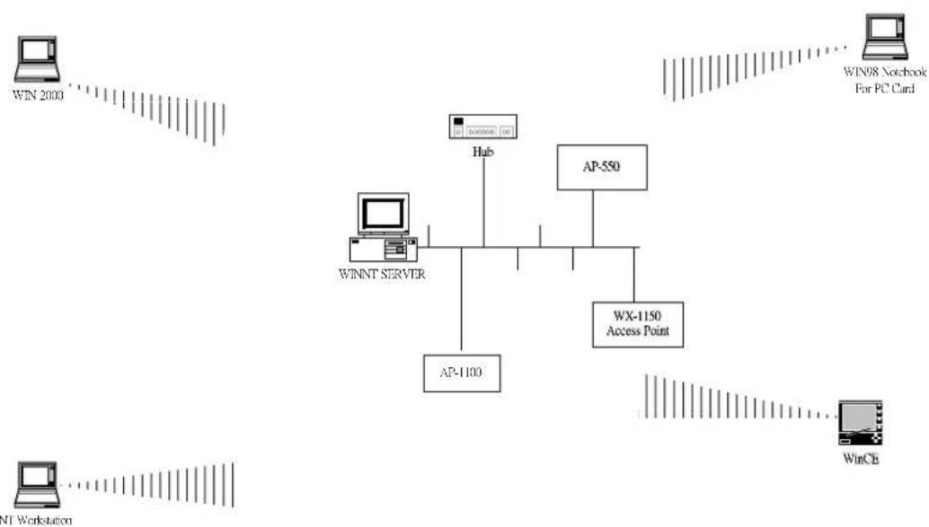
flowchart
graph TD
    A["Win 2000"] --> B["Hub"]
    C["Win98 Notebook For PC Card"] --> D["AP-550"]
    E["NI Workstation"] --> F["AP-1100"]
    G["WinCb"] --> H["WX-1150 Access Point"]
    B --> I["WINNT SERVER"]
    D --> I
    H --> I
Figure 11: Wireless LAN Diagram
Installation for Windows 98 and Windows 95 (OSR2)
The following section will provide a guide with the DWL-500 installation. First, installation of the DWL-500 drivers will be covered, along with configuring the network settings to accommodate resource sharing and selecting the type of wireless network. The DWL-500 offers the advantages of a wired LAN without the inconvenience of cable installation.
Installation Overview
Follow these steps to establish a wireless network connection:
• Install the Access Point (AP) first. An Access Point is needed when Infrastructure network mode is selected
• Install the software using the Installation Diskette.
• Install the DWL-500 into the PCMCIA slot of the laptop.
Install the network protocol(s) required to communicate on your network. In most cases, TCP/IP protocol will be used.
Installation for DWL-500
Do not insert the DWL-500 until you are asked to do so. Inserting the DWL-500 prematurely may result in an unsuccessful installation.
Follow these steps to install the DWL-500 PCI card:
- RMake sure there is an available PCI slot in your PC and a Windows 95(OSR2), 98 CD ROM.
- RCheck for an available IRQ(Interrupt Request). Turn on your computer select Start/Settings/Control Panel/System. Click on the Device Manager tab. Double click on the computer icon located on top of the Systems Properties window. On View Resources tab click Interrupt Request (IRQ) and check for available (not listed) number between 00 and 15.
- RTurn off your computer and unplug the power cord from the wall. Open the cover to the PC. Insert the DWL-500 PCI card into an open PCI slot. !Note: make sure the DWL-650 PCMCIA adapter is not inserted into the DWL-500 PCI card. Secure the DWL-500 PCI card down to the chassis of the PC.
- RAfter the DWL-500 PCI card is secured to the PC, now insert the DWL-650 PCMCIA card into the DWL-500 PCI card. !Note: Firmly insert the DWL-650 PCMCIA card into the DWL-500 PCI card. Do not use force. Proper installation of the DWL-650 PCMCIA card requires that the link light of DWL-650 PCMCIA is facing the ground.
-
RReplace the cover to your computer and turn it on.
-
RWhile Windows is starting up, it will automatically detect the PCI card bus controller as a RICOH card bus controller. The PC Card (PCMCIA) wizard will then prompt you to click next. Make sure that No is selected and click next. When asked if you want to check your system files check No and click next. When windows says PCI card is finished, click finish. If prompted, insert your Windows CD or point to your windows .cab files i.e. C:\Windows\Options\cabs then click OK.
-
RChecking the Card Bus. When windows boots up, go to Start/Settings/Control Panel/System. Click on the Device Manager Tab. Click on the + sign in front of the PCMCIA Socket. Highlight the RICOH Card Bus controller. Click on Properties button at the bottom of the window.
A. RUnder the General Tab check that the Device is working properly under device status.
B. RUnder the Resource Tab make sure there are no conflicts listed under conflicting device list.
C. RClose the window.
Follow these steps to install the drivers for the DWL-650 PCMCIA card:
- Select the DWL-500 WLAN Card & PCI Reader Setup Disk.
- RInsert the Setup Disk into the floppy drive.
- RClick Start select Run type A:\setup.exe.
A. RClick OK. Wait while your computer goes through setup.
B. RClick Next when the welcome screen pops up.
C. RClick Yes when the license agreement pops up. When Setup is complete select Yes, I want to restart.
D. RClick Finish. Note: Make sure to remove the floppy diskette from your drive before your computer restarts.
-
RWhen the computer reboots it will find the DWL-650 and ask for the windows CD again. If prompted, insert the your Windows CD or point to your windows .CAB files ie. C:\Windows\Options\cabs. Then click OK and your computer will restart again.
-
RCheck to make sure the Network Adapter is installed properly. When Windows boots up go to Start/Settings/Control Panel/System. Click on the Device Manager Tab. Click on the + sign in front of the Network Adapters. Highlight the D-Link DWL-650 11 Mbps WLAN Adapters. Click on Properties button at the bottom of the window.
A. RUnder the General Tab, check that the Device is working properly under the device status.
B. RUnder the Resource Tab, make sure there are no conflicts listed under conflicting device list.
C. RClose the window.
Follow these steps to install the Utility software for DWL-500 PCI card:
- Insert the DWL-500 WLAN Card & PCI Reader Utility Disk into the floppy drive.
- Click on Start select Run type A:\setup.exe and click OK.
- Click on Next when the welcome screen pops up. At the software license agreement screen, click Yes.
- Windows will prompt for a destination location. If you do not want to use the default location enter your choice in the text box.
- Click Next.
- Click Close when windows says it is complete.
To run the Configuration Utility:
-
Click Start/Programs/D-Link Air DWL-650 Utility/D-Link DWL-650 Control Utility.exe.
-
Four tabs will be now available for use. Status, Configuration, Encryption and About program.
Configuration Utility
DWL-500 uses the Configuration Utility software for management. The Configuration Utility, which starts automatically, is used for the initial set up of the DWL-500. To start the utility program, from the "Start" button, select Programs, then D-Link DWL-500 to manually start the Configuration Utility software if the manager application does not start automatically.
A new icon - should appear in your Icon tray, shown in the graphic and as it will appear in your icon tray, see Figure 2. If the icon is marked with a red "X", it means that the DWL-500 configuration is invalid or incomplete. Particularly the icon will be colored red when the driver setting is in Pseudo BSS mode and the radio channels set incorrectly, see Figure 3.

Figure 2: Icon tray with new icon

Figure 3: Error Icon
Double clicking on that icon will show you the screen as shown below, see Figure 4.
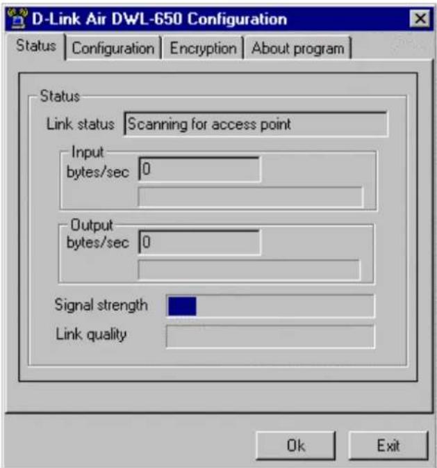
Figure 4: Management window with "Status" tab
Navigate through “sheets”, by clicking or tapping them with a stylus. “OK” button will minimize window, and “Exit” (or X button) will close application.
The first three fields show your wireless network card state.
Link status – indicates link accessibility. There are several values that can be shown in this part of the window.
Connected - BSSID=... - normal flow of operation in Infrastructure mode. The PC is connected to an access point. BSSID is shown in the form of hex digits. Networking is available.
No status... - the manager is retrieving information from the driver. If this text box value stays more than several seconds, it means that there are no access points or other workstations (if communicating in AdHoc mode), or that the DWL-500 card is plugged out of PC.
Scanning for access point - driver scans wireless network searching for available access point in Infrastructure mode.
Disabled or disconnected - if this text box value stays more than several seconds, it means that there are no access points or other workstations (if communicating in Pseudo BSS mode), or that the DWL-500 card is plugged out of PC.
Undefined – means critical driver error. This error is usually caused by hardware that has not been configured correctly (for example the card with similar chipset inserted in PC card bay, but not fully compatible with D-Link NIC).
Input bytes/sec - shows the incoming (received) data speed, the progress bar below, means receiver must load.
Output bytes/sec - shows the outgoing (sent) data speed, the progress bar below, shows
transmitter load.
Signal strength - bar shows signal strength level. The higher the blue bar is, the more powerful the radio signal received by the DWL-500 card. This indicator helps to find the most comfortable antenna/workstation position for quality network operation.
Link quality - The measured signal level gives the overall Link Quality and Connection Status.
Configuration Tab
You can change the configuration by clicking on the Configuration tab located on the top of the D-Link Air DWL-650 configuration window. Then click on the change configuration box located on the bottom of the configuration window. The grayed out screen will now be available for changes.
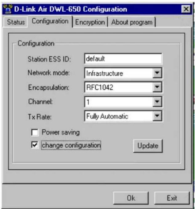
Figure 5: Management window with "Configuration" tab open.
Five fields are available to change the configuration for DWL-500. The fields are the following:
Station ESS ID:
The Station ESS ID is the group name for your wireless network.
- Extended Service Set Identifier (Wireless Network Identifier) is the group name that will be shared by every member of your wireless network. You will only be able to connect with an Access Point, which has the same Station ESS ID. To change the current Station ESS ID, simply delete default and type a new Station ESS ID, i.e. home.
Network mode:
There are two selections for network mode: Ad hoc or Infrastructure.
• Ad-hoc(PsIBSS): When in Ad hoc mode, this allows peer-to-peer networking
without an access point.- This is the 802.11b peer-to-peer mode of operation. In Ad Hoc mode only one wireless cell range is supported for each different ESS ID. All communication is done from Client to Client without the use of an Access Point.
- Infrastructure: When in Infrastructure mode, this allows wireless clients to join a wired Ethernet LAN through an access point.- This mode of operation requires the use of a D-Link Air DWL-1000AP wireless LAN access point or with other 802.11b compliant access points. All communication is done via the DWL-1000AP access point, which relays packets to other wireless Clients in the same BSS (Basic Service Set) as well as to nodes on a wired Ethernet LAN.
Encapsulation :
There are three selections for Encapsulation: None, RFC1042 and 802.1h.
- None: This setting takes the entire Ethernet frame, including the Ethernet Header, and encapsulates it into a 802.11 frame. This setting is used for Ethernet frame, including the Ethernet Header, and puts it into an 802.11 frame. This setting is here for compatibility with some older 802.11 implementations.
- RFC1042: This setting takes the DIX Ethernet frames and converts them using SNAP(Systems Network Architecture Protocol) header based on the RFC1042 standard. This mode will also convert any RFC1042 SNAP header frames to DIX Ethernet frames before transmission to the Ethernet interface.
- 802.1h: This setting allows the DIX Ethernet frames to be tunneled using a full selective translation table. This mode does not convert RFC1042 SNAP header frames to DIX Ethernet before transmission to the Ethernet interface.
!Note: It is required to select the encapsulation mode corresponding to the one your access point or other workstations use. If the encapsulation mode is incorrect, the PC will join to an access point or will be seen by other workstations, but network operation will not work.
Channel:
There is a total of 11 separate channels that can be selected for your wireless network.
- Channels 1 through 11 can be selected for your wireless network. Channel 1 is the factory default channel that comes with your D-Link Air DWL-500 PCI wireless adapter.
!Note: Infrastructure Client nodes will always go the same channel as their AP. Please see the table for the requirements of different countries and the channel frequency.
TX Rate:
The TX Rate is the transmission rate at which the data packets are transmitted by the client or AP. Here are the available selections:
- Fully Automatic
• 11 Mbit - 5.5 Mbit
• Auto 1 or 2 Mbit
• 2 Mbit - 1 Mbit
!Note: Setting the transfer rate of the DWL-650 faster than the access point's maximum transfer rate may produce undesired results.
Encryption Tab
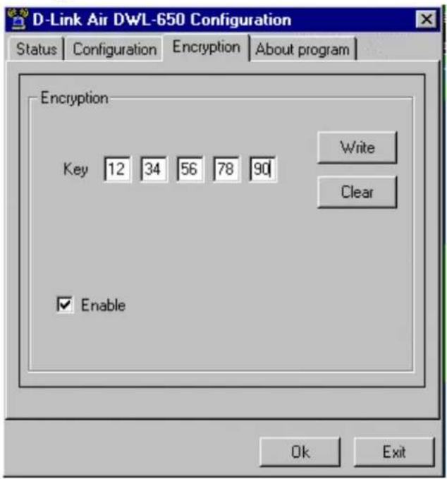
Figure 5: Management window with "Encryption" tab open
One may desire an additional measure of security on your wireless network, which can be achieved by using WEP (Wired Equivalent Privacy) encryption. WEP encrypts each frame transmitted from the radio using one of the Keys entered from this panel. See
When an encrypted frame is received, the frame will only be accepted if it decrypts correctly. This will only happen if the receiver has the WEP Key used by the transmitter.
This panel allows the entry of four keys, which can then be written to the driver and registry. Each key must consist of hex digits; it means that only digits 0-9 and letters A-F are valid entries. If entered incorrectly program will not write keys to a driver.
• Key 1 – Key 4: These four fields must be used to enter the keys.
• Write: This button updates the driver with the four keys displayed in Key 1 through Key 4. The keys are also written to the registry for permanent storage.
- Clear: This button clears all the bytes in the four keys, useful when entering and when you wish to start over.
- Default Key: This pop-up field defines one of the four keys, which will be used by the driver to encrypt frames it will be transmitting. This field does not affect decryption, as the driver can decrypt any frame that it receives which was encrypted with one of the four keys.
- Enable: This checkbox enables or disables encryption operation. When it is checked, encryption is enabled, and when unchecked – encryption is disabled. The corresponding action is written to a driver immediately.
"About" tab
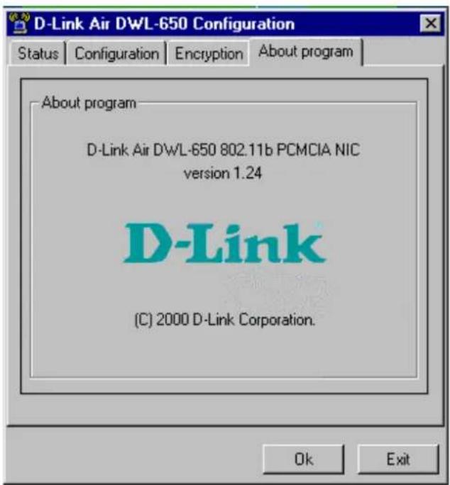
Figure 6: Management window with "ABOUT" tab open
About tab shows a software version. Users must use this version number when reporting their problems to tech support.
Troubleshooting
To make the installation of the DWL-500 user friendly, D-Link suggests that the installation steps be followed as listed in section 4 and section 5. However, if problems are encountered during the DWL-500's installation process, follow the steps outlined below for troubleshooting. In the first part of the Troubleshooting section, check the properties of the card to verify that the DWL-500 has been installed properly. In second section, the most common problems encountered during the installation are listed along with the possible solution. Please check the first part to derive the probable reason of unsuccessful installation.
Procedure to Check the Various Properties of Card after Installation under Windows 95 (OSR2)/98:
Please check the followings if problems are encountered while installing the DWL-500 card or if DWL-500 card is not functional.
- Click on the Start/Settings/Control Panel/System/Device Manager tab/click on the + sign next to Network Adapters. Double click on the D-Link DWL-650 11Mbps WLAN Adapter. Select the Resources tab, check the Conflicting device list: window; it should read “no conflicts”.
- Check and verify that D-Link DWL-650 11Mbps WLAN Adapter is properly installed. If there is a yellow exclamation or red X then installation of the DWL-500 PCI card did not install properly, reinstall the DWL-500 PCI card and DWL-650 PCMCIA card.
- Check whether there are available IRQ's, check that the DWL-650 PCMCIA card is properly inserted into the DWL-500 PCI card. If the Yellow sign or Question-mark (?) is displayed, then check that there are no resource conflict between the DWL-500 and another device.
Technical Specifications of DWL-500 PCI Card
Hardware compatibility
IBM-compatible computer with a PCI slot
Driver support
NDIS 3.1
- Windows 95 OSR2
- Windows 98
- Windows NT 4 and higher
- Linux
- WinCE(x86,SH4,MIPS)
Standards supported
- IEEE 802.11 standard for Wireless LAN
- All major networking standards (including TCP/IP, IPX)
Environmental
Operating temperature (ambient):
- -10°C to 50°C (Operating), -20 to 70°C (Storing)
- Max. Humidity: 95% Non-condensing
Power specifications
Operating voltage:
- +5 V, +3.3V DC ±5%
- Nominal Temp Range: 17 dBm
- Extended Temp Range: 14 dBm min.
- Transmit Power, 2.7v to 3v: 14 dBm min.
Radio specifications
Range:
- per cell indoors approx. 35-100 meters or more
- per cell outdoors up to 100-300 meters
Frequency range:
- 2.4-2.4835 GHz, direct sequence spread spectrum
Number of Channels:
- Europe: 13 (3 non-overlapping)
- US: 11 (3 non-overlapping)
- France: 4 (1 non-overlapping)
- Japan: 14 (4 non-overlapping)
Antenna system:
- Internal patch antenna supporting diversity.
Mobility:
- Seamless roaming across cell boundaries with handover
Specific features
Supported bit rates:
- 11 Mbps
- 5.5 Mbps
- 1 Mbps
- 2 Mbps
Data encryption:
- 40 bit WEP Encryption
Utility Software:
- Management utility software
Key Management:
- Automatic Dynamic Key Allocation (ADKA) through public key
Physical Dimensions
- Extended type-II PC Card 110 x 54 x 6 mm
Index
802.1h, 14
About Tab, 16
cabling, ii
Channel, 14
Clear, 15
Configuration, 11
Configuration tab, 13
Connected BSSID, 12
Default Key, 15
Disabled or Disconnected, 13
Enable, 16
Encapsulation, 14
Encryption Tab, 15
Infrastructure, 14
Input bytes, 13
Installation, 10
Key, 15
link quality, 13
Link status, 12
Network Mode, 14
No status, 12
None or Encapsulated, 14
Output bytes, 13
Pseudo BSS, 14
RFC1042, 14
Scanning for access point, 12
Signal strength, 13
Station ESS ID, 14
Troubleshooting, 17
TX Rate, 14
Undefined, 13
Wireless LAN basics, 8
Write, 15
- D-Link Air DWL-500 IEEE 802.11b PCI Wireless LAN Adapter
- Certifications
- CE Mark Warning
- VCCI Warning
- What You Must Do For Warranty Service:
- What Is Not Covered:
- Table of Contents
- Introduction
- Wireless LAN Basics
- Installation for Windows 98 and Windows 95 (OSR2)
- Installation Overview
- Installation for DWL-500
- Follow these steps to install the drivers for the DWL-650 PCMCIA card:
- Follow these steps to install the Utility software for DWL-500 PCI card:
- To run the Configuration Utility:
- Configuration Utility
- Configuration Tab
- Station ESS ID:
- Network mode:
- Encapsulation :
- Channel:
- TX Rate:
- "About" tab
- Troubleshooting
- Procedure to Check the Various Properties of Card after Installation under Windows 95 (OSR2)/98:
- Technical Specifications of DWL-500 PCI Card
- Hardware compatibility
- Driver support
- Standards supported
- Environmental
- Power specifications
- Radio specifications
- Range:
- Frequency range:
- Number of Channels:
- Antenna system:
- Mobility:
- Specific features
- Supported bit rates:
- Data encryption:
- Physical Dimensions
- Index
Brand : D-LINK
Model : DWL-500
Category : Network card