CB-MXP10-F - Boîtier mural pour appareil électronique AMX - Free user manual and instructions
Find the device manual for free CB-MXP10-F AMX in PDF.


| Product Type | Audio/Video Processor |
| Brand | AMX |
| Model | CB-MXP10-F |
| Mounting | 19-inch Rackmount, 1U |
| Dimensions (W x D x H) | 48.3 x 25.4 x 4.4 cm (19 x 10 x 1.75 in) |
| Weight | 2.3 kg (5.1 lbs) |
| Power Supply | 100-240 VAC, 50/60 Hz, 30 W max |
| Inputs | 4x HDMI, 2x Analog Stereo, 1x Microphone |
| Outputs | 2x HDMI, 1x Analog Stereo, 1x S/PDIF |
| Control Interface | Ethernet, RS-232, IR, GPIO |
| Audio Formats | Dolby Digital, DTS, PCM up to 7.1 |
| Video Resolution | Up to 4K@60Hz 4:4:4 |
| HDCP | 2.2 compliant |
| Main Functions | Audio de-embedding, scaling, routing, and control |
| Operating Temperature | 0°C to 40°C (32°F to 104°F) |
| Storage Temperature | -20°C to 60°C (-4°F to 140°F) |
| Humidity | 10% to 90% non-condensing |
| Cooling | Fanless, passive cooling |
| Cleaning | Wipe with dry, soft cloth; no liquids |
| Safety | Overcurrent protection, CE, FCC compliant |
| Spare Parts | Contact AMX support for replacement |
| Repair | Return to authorized service center |
Frequently Asked Questions - CB-MXP10-F AMX
User questions about CB-MXP10-F AMX
0 question about this device. Answer the ones you know or ask your own.
Ask a new question about this device
Download the instructions for your Boîtier mural pour appareil électronique in PDF format for free! Find your manual CB-MXP10-F - AMX and take your electronic device back in hand. On this page are published all the documents necessary for the use of your device. CB-MXP10-F by AMX.
USER MANUAL CB-MXP10-F AMX
The CB-MXP10-F Flush Mount Rough-In Box (FG5968-84) is an optional accessory for the Modero X Series 10" Wall Mount Touch Panel. It is designed to be flush mounted onto solid walls (rock, concrete, adobe, cinder block) or drywall applications.
The back of the Modero X Series 10" Wall Mount Touch Panel is contained within a plastic outer housing or back box, and the back box attaches to the Rough-In Box. The Rough-In Box kit includes a wall box, cover, and mounting screws.
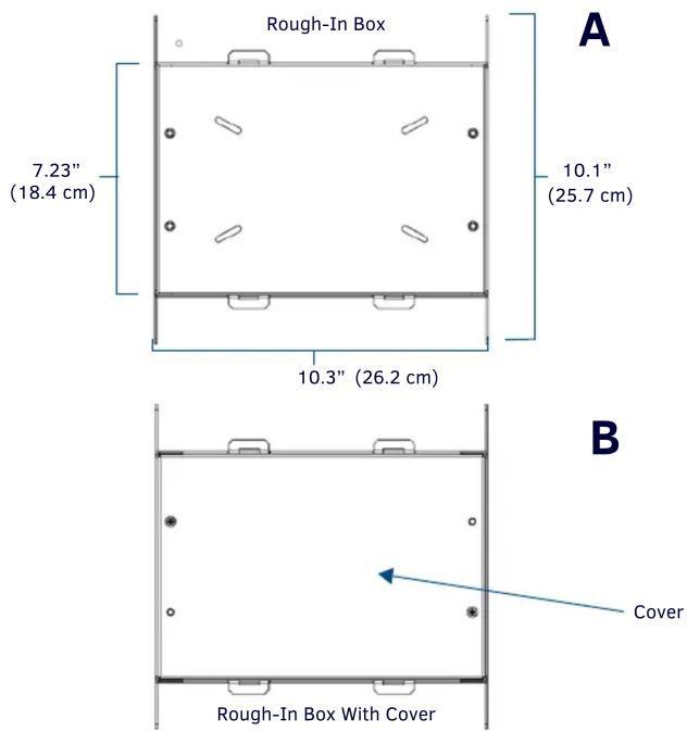
FIG. 1 CB-MXP10-F ROUGH-IN BOX
Specifications
CB-MXP10-F SPECIFICATIONS
| Dimensions (HWD) • Rough-In Box: 10.1" x 10.3" x 3.64" (25.7 cm x 26.2 cm x 9.25 cm) | |
| Weight • Without cover: 1.80 lbs (0.82 kg) | |
| Certifications • UL Listed | |
| Included Accessories: | • Cover Plate to cover Rough-In Box (62-5968-93)• Rough-In Box Cover Mounting Screws (2) (80-5967-04) |
Wall Mount Install of the CB-MXP10-F Rough-In Box
- Remove the cover (B in FIG. 1) off of the rough-in box (A) before installation.
CAUTION: The cutout dimensions shown will allow the unit to pass through without any dragging or interference. The outer phantom lines show the perimeter of the mounting flange. If any part of the cutout extends up to or beyond that perimeter, the cut edge will be visible after installation, or the unit could fall through the opening.
Solid Wall Construction
- Cut a hole in the wall using best practices according Fig D below.
- Insert the box into the cutout until the front tabs are seated flush (Fig D).
- Screw or anchor to the wall through some of the various holes in the sides and back of the box. Snap off the four tabs once box is secured and continue with step 5 below.
Drywall and Stud Mounting
- Break the four bent tabs around the front of the box off (Fig C).
- Mount the metal box with its leading edge flush with the stud.
- Remove the appropriate wiring knockouts from the rough-in box to accommodate the cables being threaded through to the wall mount touch panel.
- Thread the incoming Ethernet and USB wiring through the knockouts. Using the left wiring knockouts for USB connector cables and the right wiring knockouts for the LAN/PoE In cable is very highly recommended with this installation. Leave enough slack in the wiring to accommodate installation of the docking station.
- After drywall is installed (with cover removed), use a rotary cutting tool or drywall saw to cut to the inside dimensions of the rough-in box. If using the included front cover, small notches may be needed to clear the four raised tabs on the cover. Do not shave off more drywall than necessary for clearance to insure that the flush mount kit will cover the entire opening after installation.
NOTE: The front cover (B in FIG. 1) should be installed after the appropriate wiring is pulled to the Rough-In Box. The cover should then be removed prior to the installation of the touch panel back box and discarded.


Brand : AMX
Model : CB-MXP10-F
Category : Boîtier mural pour appareil électronique