MXA-FMK-20 - Wall mount AMX - Free user manual and instructions
Find the device manual for free MXA-FMK-20 AMX in PDF.


| Product Type | Wall mount for flat panel displays |
| Brand | AMX |
| Model | MXA-FMK-20 |
| Compatible VESA Patterns | 200x200mm to 600x400mm |
| Maximum Display Weight | 50 kg (110 lbs) |
| Display Size | 32" to 65" |
| Material | Heavy-duty steel |
| Finish | Black powder coat |
| Overall Dimensions (W x H x D) | 700 x 500 x 55 mm |
| Weight | 4.5 kg |
| Mounting Type | Fixed (low profile) |
| Tilt Adjustment | No (fixed mount) |
| Level Adjustment | Yes, ±3° |
| Professional Installation | Recommended |
| Compliance | TUV, UL listed |
| Included Hardware | M4, M5, M6, M8 screws and spacers |
| Max Distance from Wall | 25 mm |
| Warranty | 5 years |
| Cleaning Instructions | Wipe with a soft, dry cloth. Do not use abrasive cleaners. |
| Periodic Maintenance | Check all screws and bolts monthly for tightness. |
| Spare Parts Availability | Contact AMX customer service for replacement hardware. |
Frequently Asked Questions - MXA-FMK-20 AMX
User questions about MXA-FMK-20 AMX
0 question about this device. Answer the ones you know or ask your own.
Ask a new question about this device
Download the instructions for your Wall mount in PDF format for free! Find your manual MXA-FMK-20 - AMX and take your electronic device back in hand. On this page are published all the documents necessary for the use of your device. MXA-FMK-20 by AMX.
USER MANUAL MXA-FMK-20 AMX
The MXA-FMK-20 Flush Mount Kit (FG5968-68) allows the Modero X 20.3" Wall Mount Touch Panels to be installed totally flush with the wall. The MXA-FMK-20 is compatible with all Modero X 20.3" Wall Mount Touch Panels including:
- MXD-2001-PAN-P (FG5968-36) - MXD-2000XL-PAN-L (FG5968-11)
- MXD-2001-PAN-L (FG5968-37) - MXD-2000XL-PAN-P-NC (FG5968-33)
- MXD-2000XL-PAN-P (FG5968-05) • MXD-2000XL-PAN-L-NC (FG5968-34)
PRODUCT SPECIFICATIONS
| Dimensions (HWD): 10 | 5/16" x 20 7/8" x 3" (261.82 mm x 530.32 mm x 76.2 mm) |
| Weight: 8.45 lbs (3.83 kg) | |
| Included Accessories: | 10 6-32 x .375 screws (80-0137-03)8 trim frame spacers (66-5968-47)MXA-FMK-20 Flush Mount Kit Template (68-5968-09)MXA-FMK-20 Quick Start Guide (93-5968-68) |
Installation of the Flush Mount Kit
The MXA-FMK-20 Flush Mount Kit is designed to attach the touch panel to most standard wall and solid surface materials.
Note: To guarantee a stable installation of the MXA-FMK-20, the thickness of the wall material must be a minimum of .50 inches (1.27cm) and a maximum of .875 inches (2.22cm). The surface should also be smooth and flat.
After ensuring proper placement, cut out the mounting surface, using the MXA-FMK-20 Flush Mount Kit Template (68-5968-09) as a guide (FIG 1).
CAUTION: The cutout dimensions shown will allow the unit to pass through without any dragging or interference. The outer border shows the perimeter of the mounting flange. If any part of the cutout extends up to or beyond that perimeter, the cut edge will be visible after installation, or the unit could fall through the opening. A larger cutout reduces the available surface to support the unit when mounted, so the cut should be as close to the indicated dimensions as possible. If the cutout is too small, forcing the unit into place could result in mechanical binding, faulty operation, or damage to the product. Always check for a proper fit before final installation.

FIG. 1 MXA-FMK-20 CUTOUT TEMPLATE (PORTRAIT ORIENTATION)
A - These six notches serve as clearance for the drywall expansion clips. If you are not using the drywall expansion clips, DO NOT cut these notches into the mounting surface.
B - These four notches are clearance notches for the screw heads on the sides of the wall frame. These notches must be cut.
WARNING: Cut to the inner perimeter of the template. Do NOT cut to the outer perimeter.
Note: Before installing the touch panel in the wall, check the flush alignment of the panel in the frame. Install the panel in the wall frame, and push it in to its recessed position (see step 10). Lay the trim ring over the unit to check the relative position of the touch panel with the trim ring face. Note that the unit should be oriented as it will sit in the wall as gravity can have an effect on the final position of the panel. I are not coplanar, use the four set screws to adjust the depth of the installed panel until it is flush with the trim ring (see FIG. 2). Only small adjustments (if any) of one turn or less should be required. Adjusting the position too far could result in the catch not having enough room to engage. After completing the adjustments, test that all catches engage and release. Remove the panel and proceed with wall installation.
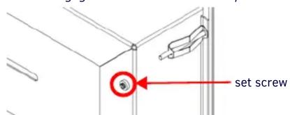
FIG. 2 SET SCREWS ARE LOCATED ON THE BASE OF THE WALL FRAME, ONE IN EACH CORNER
Installing the Wall Frame
- Remove the appropriate knockouts from the wall frame to accommodate the cables being threaded through to the touch panel (FIG. 3).

FIG. 3 WALL FRAME KNOCKOUTS
- Ensure the corresponding wiring knockouts in the back box have been removed, and place the back box into the wall frame. Align the screw holes in the back box with the standoffs in the wall frame (FIG. 4).

FIG. 4 ALIGN SCREW HOLES IN BACK BOX WITH STANDOFFS IN WALL FRAME
- Use the 6-32 screws included with the flush mount kit to affix the back box to the wall frame.
- Before installing the wall frame, thread the incoming Ethernet and power wiring through the knockouts in the wall frame. Position the cables in the cable guide slots to prevent interference with the edge of the cutout during installation.
- Install the wall frame into the wall. Secure it into place by tightening the drywall clips.
Note: If mounting the panel in a harder surface than drywall, use masonry screws (not provided) to secure the wall frame into the wall.
- Insert each connector into its corresponding location along the back of the touch panel. For more information, consult the Quick Start Guide for the panel being installed.
- Test the incoming wiring by attaching the touch panel connections to their terminal locations and applying power. Verify that the panel is receiving power and functioning properly to prevent repeating the installation.
Note: Do not disconnect the connectors from the touch panel. The unit must be installed with the attached connectors before being inserted into the wall.
- Use the 4 pilot pins on the panel as guides to mount the touch panel onto the back box (FIG. 5). Ensure the pilot pins are secured firmly in place.
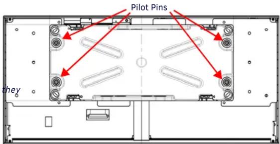
FIG. 5 INSERT PILOT PINS INTO MARKED LOCATIONS
- Use the included 4-40 screws to secure the touch panel onto the back box (FIG. 6). There are five screw holes to use for securing the panel on the left and right side of the back box (landscape installation; for a portrait installation, the holes are located on the top and bottom of the back box.)
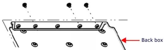
FIG. 6 SECURE THE PANEL TO THE BACK BOX VIA SCREW HOLES IN BACK BOX
Note: Use a screwdriver or other flat tool to hold the edge of the clear back box casing for additional ease applying the screws.
- Push the touch panel into the wall frame evenly all around until you begin to feel resistance from the spring catches. You should begin to feel resistance when the panel is about halfway into its recessed position. The panel glass should be parallel to the wall with no edge tilted in further than any other edge. In a portrait orientation, start by pressing the bottom two corners of the panel. Do not release pressure until both corners have clicked into place. Press the top two corners and, once again, do not release until you hear both clicks. When unlocking the panel, begin with the bottom corners, then proceed to the top corners.

FIG. 7 PRESS FLAT ON THE CORNER AREA OF THE TOUCH PANEL TO LOCK IT IN PLACE
Note: If one corner does not click, try pushing in that area again to engage the catch. If it still does not click, do not try to force it. Release all four corners and start again. If it still does not click in, check to see if the panel glass is free to move into the wall frame. If the edge of the glass contacts the edge of the metal, call tech support before proceeding.
- Insert the small end of the trim spacers between the touch panel and the wall frame, inserting two spacers into each corner of the panel, and fold the spacer on its crease until the adhesive (larger) side of the spacer is on the panel.
- Apply the cosmetic frame to the outside of the touch panel. Remove the adhesive protector along each side of the interior frame before applying the frame. Once adhered, remove the exterior protective film for the frame.
- Remove the trim spacers from the touch panel.
Using the MXA-FMK-20
Once the touch panel is installed in the MXA-FMK-20, the panel may be extended from the wall for enhanced speaker and microphone exposure and to access the panel's Sleep/Setup button. To extend the panel from the Flush Mount Kit, press the bottom two corners of the panel and do not release pressure on until you hear both corners click out of their locked position. Perform the same action on the top corners. Release the panel to extend it.
To return the touch panel to its flush position, see step 10 above.
Removing the Touch Panel from the MXA-FMK-20
The touch panel may only be removed from the MXA-FMK-20 when the touch panel is extended from the wall. To remove the touch panel from the MXA-FMK-20, remove the screws that attach the touch panel to the back box, and disconnect any wiring connected the panel's terminal locations.
Additional Documentation
For more information the touch panel, please refer to the Operation Reference Guide of the panel, available at www.amx.com.
A Note About Wall and Rack Installation
Some products are installed in areas of differing temperature and cooling methodologies. These include products installed in walls, racks, cabinets, etc. Those areas may have different temperatures and/or cooling approaches that must be taken into consideration to maintain the product within the specified operating temperature.
FIG. 8 shows an AMX device installed in a wall with a filled volume (such as with insulation or concrete), as well as with a closed volume (such as between studs in otherwise finished wall). The diagram shows how heat generated by the device or other devices may have no way to escape, and may build up to levels that may affect device operation.
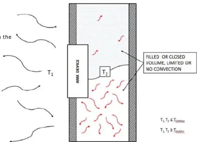
FIG. 8 HEAT CONVECTION IN FILLED OR CLOSED VOLUME, LIMITED OR NO CONVECTION
In FIG. 9, the diagram displays an AMX device in a typical rack mounting, with full air circulation around the front and back of the device. In this case, the main concern is with heat building up between components, possibly to levels that may affect device operation.

FIG. 9 HEAT CONVECTION IN RACK-MOUNTED DEVICES
Installation Recommendations
During any installation, a lack of ventilation may produce conditions that may adversely affect the device's operation. In these circumstances, special care must be made to make sure that temperatures within enclosed areas do not exceed the device's maximum rated temperature.

- INSTALLATION OF THE FLUSH MOUNT KIT
- WARNING: CUT TO THE INNER PERIMETER OF THE TEMPLATE. DO NOT CUT TO THE OUTER PERIMETER
- INSTALLING THE WALL FRAME
- USING THE MXA-FMK-20
- REMOVING THE TOUCH PANEL FROM THE MXA-FMK-20
- ADDITIONAL DOCUMENTATION
- A NOTE ABOUT WALL AND RACK INSTALLATION
- INSTALLATION RECOMMENDATIONS
Brand : AMX
Model : MXA-FMK-20
Category : Wall mount