
CB-TP5i - Wall mount AMX - Free user manual and instructions
Find the device manual for free CB-TP5i AMX in PDF.


| Product Type | Rough-In Box (Wall Mount Accessory) |
| Brand | AMX |
| Model | CB-TP5i (FG038-11) |
| Dimensions (HxWxD) | 6.73" x 9.30" x 1.43" |
| Dimensions (HxWxD) Metric | 17.09 cm x 23.62 cm x 3.63 cm |
| Certifications | UL 508A |
| Minimum Distance from Wall Surface | 0.50" (1.27 cm) |
| Maximum Distance from Wall Surface | 0.875" (2.22 cm) |
| Compatible With | NXD-500i Modero Wall/Flush Mount Touch Panel |
| Material | Plastic outer housing (Back Box) |
| Mounting Type | Stud mount (to pre-wall/studs) |
| Included Components | Rough-In Box, cover (must be removed before drywall) |
| Optional Accessories | Back Cover FG038-12, screws 4-40 (not included) |
| Mounting Hardware | Nails or screws (not provided) |
| Screw Holes | Stud Mounting tabs with holes |
| Wiring Knockouts | Left side recommended for Ethernet and USB cables |
| Drywall Installation | Install drywall after box, cut opening slightly smaller than template |
| Break-Away Flanges | Yes, for adjustment |
| Usage | For pre-wall mounting of touch panel |
| Repairability | Accessible via back box; replacement parts available |
Frequently Asked Questions - CB-TP5i AMX
User questions about CB-TP5i AMX
0 question about this device. Answer the ones you know or ask your own.
Ask a new question about this device
Download the instructions for your Wall mount in PDF format for free! Find your manual CB-TP5i - AMX and take your electronic device back in hand. On this page are published all the documents necessary for the use of your device. CB-TP5i by AMX.
USER MANUAL CB-TP5i AMX
The CB-TP5i Rough-In Box (FG038-11) is an optional accessory for the NXD-500i Modero® Wall/Flush Mount Touch Panel. The Rough-In Box allows the panel to be mounted directly to the studs/pre-wall. The NXD-500i is contained within a plastic outer housing or back box, and the back box attaches to the Rough-In Box.
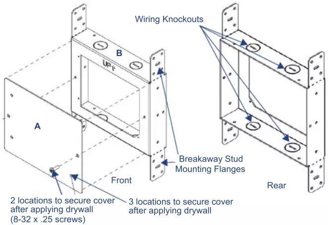
FIG. 1 CPB-TP5i Rough-In Box - Front and Back Views
Specifications
| CB-TP5i (FG038-11) Specifications | |
| Dimensions (HWD) | 6.73" x 9.30" x 1.43"• 17.09 cm x 23.62 cm x 3.63 cm |
| Certifications • UL 508A | |
WARNING: In order to guarantee a stable installation of the NXD-500i, the distance between the CB-TP5i and the outer wall surface must be a minimum of .50 inches (1.27cm) and a maximum of .875 inches (2.22cm).
- Refer to the SP62-0038-01 diagram for detailed installation dimensions.
Pre-Wall Installation of the CB-TP5i Rough-In Box
- Remove the rough-in box cover (A in FIG. 1) before installation of the Rough-In Box (B). Note: the cover MUST be removed before drywall installation. The cover may be reinstalled after drywall installation using 4-40 screws (not included).
- Attach the optional Back Cover for the CB-TP5i (FG038-12) if necessary, as required by building codes. (For more information, refer to the Back Cover Installation section on page 2.)
- Fasten the CB-TP5i rough-in box to the stud through the holes on the Stud Mounting tabs (FIG. 2), using either nails or screws (not provided).

FIG. 2 CB-TP5i - Mounted to Wall Stud
- Remove the appropriate wiring knockouts from the rough-in box to accommodate the cables being threaded through to the NXD-500i touch panel.
- Thread the incoming Ethernet and USB wiring through the knockouts. Use of the left wiring knockouts is recommended with this installation for ease of connection of the cables to the touch panel. Leave enough slack in the wiring to accommodate installation of the panel.
- Install the drywall/sheetrock before inserting the main NXD-500i device into the CB-TP5i.
- Cut out the opening for the NXD-500i where the wall has been placed over the Rough-In Box. Cutting out the surface slightly smaller than what is outlined in the installation drawings, so that you can make any necessary cutout adjustments, is very highly recommended.


CB-TP5i Break-Away Flange detail


Back Cover Installation

Assembly of CB-TP5i and Back Plate
Screws (80-0114-01), #4-20 x .375
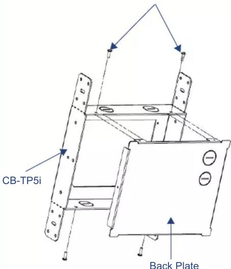
Note: two screw holes in flanges at top and bottom of Back Plate, but one screw hole per flange on sides.
Side of Rough-In Box
With Break-Away Flanges
Brand : AMX
Model : CB-TP5i
Category : Wall mount