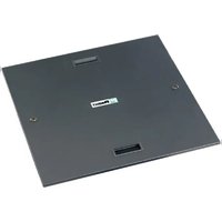
PZRFC - Enceinte pour plancher technique Panduit - Free user manual and instructions
Find the device manual for free PZRFC Panduit in PDF.


| Product Type | Fiber Optic Connector |
| Connector Type | LC Duplex |
| Fiber Mode | Multimode |
| Core/Cladding Diameter | 62.5/125 µm |
| Insertion Loss (Typical) | ≤ 0.2 dB |
| Return Loss (Min) | ≥ 20 dB |
| Durability (Mating Cycles) | 1000 |
| Operating Temperature Range | -40°C to +85°C |
| Ferrule Material | Ceramic |
| Housing Material | Plastic |
| Color | Beige |
| Dimensions (L x W x H) | 1.5 x 0.5 x 0.4 in (38.1 x 12.7 x 10.2 mm) |
| Weight | 2 g |
| Packaging | Individually packaged |
| Application | Data center, LAN, telecommunication |
| Certifications | RoHS compliant, TIA/EIA-604-2 |
| Maintenance | Clean with lint-free wipes and isopropyl alcohol; inspect with microscope |
| Safety | Do not look into fiber end; avoid sharp bends |
| Spare Parts / Repairability | Non-repairable; replace if damaged |
| General Information | Panduit PZRFC is a high-performance LC duplex multimode fiber optic connector for reliable network connections. |
Frequently Asked Questions - PZRFC Panduit
User questions about PZRFC Panduit
0 question about this device. Answer the ones you know or ask your own.
Ask a new question about this device
Download the instructions for your Enceinte pour plancher technique in PDF format for free! Find your manual PZRFC - Panduit and take your electronic device back in hand. On this page are published all the documents necessary for the use of your device. PZRFC by Panduit.
USER MANUAL PZRFC Panduit
The following items are included with PZRFE4/8/12
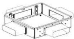
(1) Enclosure with (4) Grommet Sleeves

(4) Support Brackets, with Washers and Nuts

(1) Magnetic Ruler

(4) Bonding Bolts
Required Tools
*10mm Socket *7/16" Socket
Optional Components: PZRFC
(1) Set of Keys

(1) Lockable Enclosure Cover
PZRFE4U PZRFE8U
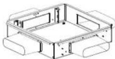
PZRFE12U


natural_image
Isometric line drawing of a mechanical housing or enclosure with internal compartments and mounting features (no text or symbols)Mounting Depth Table
Distance from bottom of pedestal head plate to top of mounting brackets.
| Part Number | PZRFE4U | PZRFE8U | PZRFE12U |
| Mounting Bracket Depth Below Floor | 5" 8.5" 12" | ||
| With Optional Cover | 7" | 10.5" 14" | |
| Enclosure Load Rating | 18 lb 36 lb | 54 lb |
(+ .25" Tolerance)
Installation:
- Select the installation location ensuring there are no obstacles to interfere with the installation.
- Mount the four support brackets under the enclosure by placing one on each pedestal mount bracket by attaching the U-bolt and nut around the pedestal (See Figure 2.1). Refer to Figures 4.1 through 4.3 for adjustment to various pedestal sizes. Use the magnetic ruler to measure the correct mounting location for each support bracket. Point them towards the center making a cross from the corners (See Figure 2.2). Ensure that the plate is allowed to pivot from side-to-side. Note: If Grid Runner is placed above pedestal plate, then the mounting assembly must be removed from plate and reconnected with the mounting assembly under the pedestal plate (See Figure 2.3).
- Push CoolBoot Assemblies inside enclosure (See Figure 3.1) and then insert the enclosure in the desired floor tile.
Figure 2.1

natural_image
Technical line drawing of a mechanical device with a U-shaped component and vertical alignment lines (no text or symbols)Figure 2.3
Figure 3.1

natural_image
Mechanical assembly diagram showing a bracket with bolts and a hanging component (no text or symbols)Mounting assembly connected under pedestal mount plate.

natural_image
Technical line drawing of a mechanical assembly with mounting base and support legs (no text or symbols)Figure 2.2

natural_image
Technical line drawing of a structural frame with supports and mounting points (no text or symbols)FOR TECHNICAL SUPPORT www.panduit.com/resources/install_maintain.asp
Installation of Pedestal Mount Assembly to Various Pedestal Sizes:
- The PZRFE*U may be mounted to 7/8" square or up to 2" diameter round pedestals by adjusting the engagement of the U-Bolt.
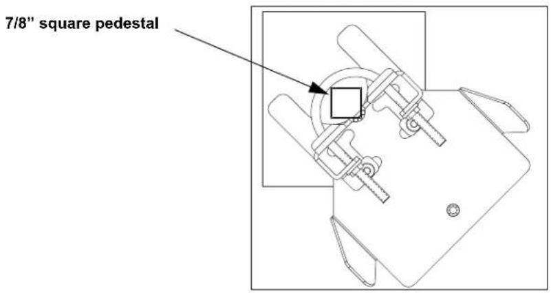
Figure 4.1

Figure 4.2

Figure 4.3
Installation continued:
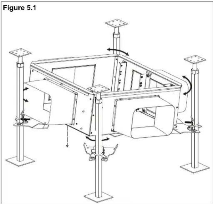
- Angle one side of the enclosure lower than the other to engage two pedestal mounting brackets. Then rock the enclosure clockwise and counter clockwise while lowering the opposite side on the pedestal mounting brackets to manually align the four corners and mounting hole locations (See Figure 5.1 & 5.2).
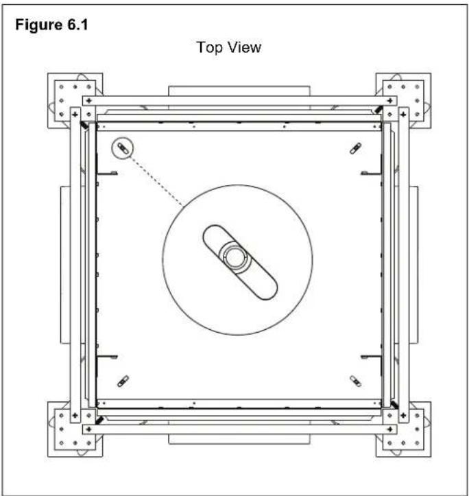
- Once all four corners and mounting holes are aligned in the correct orientation (See Figure 6.1), fasten the enclosure to the pedestal mounting brackets using the supplied M6 X 12mm bonding bolts (See Figure 6.2).
natural_image
Technical line drawing of a mechanical assembly with rotating components and support posts (no text or symbols)

Installation continued:
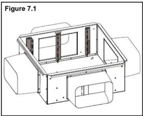
- Each enclosure can accommodate both field terminated or pre-terminated connectivity. If using field terminated connectivity leave TIA/EIA 19" mounting brackets as factory installed or remove center mounting bracket (See Figure 7.1 and 7.2). If using pre-terminated connectivity (example: cassettes, enclosures) remove TIA/EIA 19" mounting brackets and relocate to the center of the enclosure (See Figure 7.3).
natural_image
Technical line drawing of a mechanical housing or enclosure with internal compartments and mounting points (no text or symbols)
natural_image
Technical line drawing of a mechanical housing or enclosure with no visible text or symbols
natural_image
Technical line drawing of a mechanical housing or enclosure with internal compartments and mounting points (no text or symbols)Note: Install all cabling in accordance with NEC article 300.22 and Article 800.
Cool Boot Application
Parts List:
(A) - Fabric & (B) - Hook and loop cinch tie


natural_image
Technical line drawing of a mechanical housing or enclosure with a black cable inserted, labeled 'a.)' (no text or symbols on the diagram itself)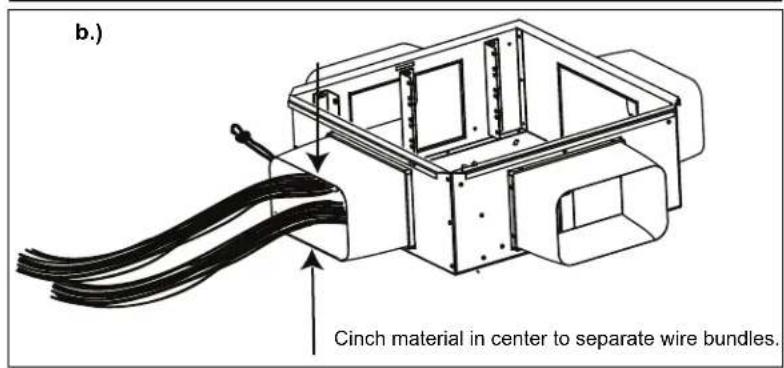
Optional: PanZone Raised Floor Enclosure Cover (PZRFC)
Enclosure's Cover Installation:

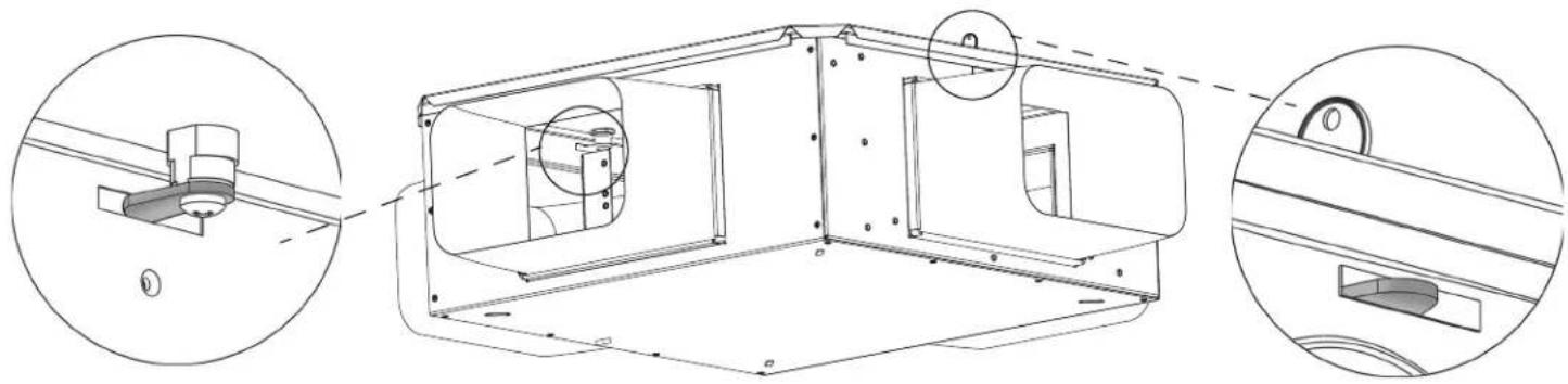
Remove the two knockout tabs located at the top of the enclosure to allow access for the cover's locking mechanism, as shown in Figure 8.


Once the knockouts have been successfully removed, drop the cover

natural_image
Technical illustration of a mechanical assembly with two views showing structural components (no text or symbols)
The cover's locking mechanism tabs should be aligned in the knockout geometry as shown in Figure 10.
natural_image
Technical line drawing of a mechanical housing assembly with three orthographic views (no text or symbols)For Instructions in Local Languages and Technical Support:
www.panduit.com/resources/install_maintain.asp
PANDUIT
www.panduit.com
E-mail:
This page intentionally left blank.
Brand : Panduit
Model : PZRFC
Category : Enceinte pour plancher technique